

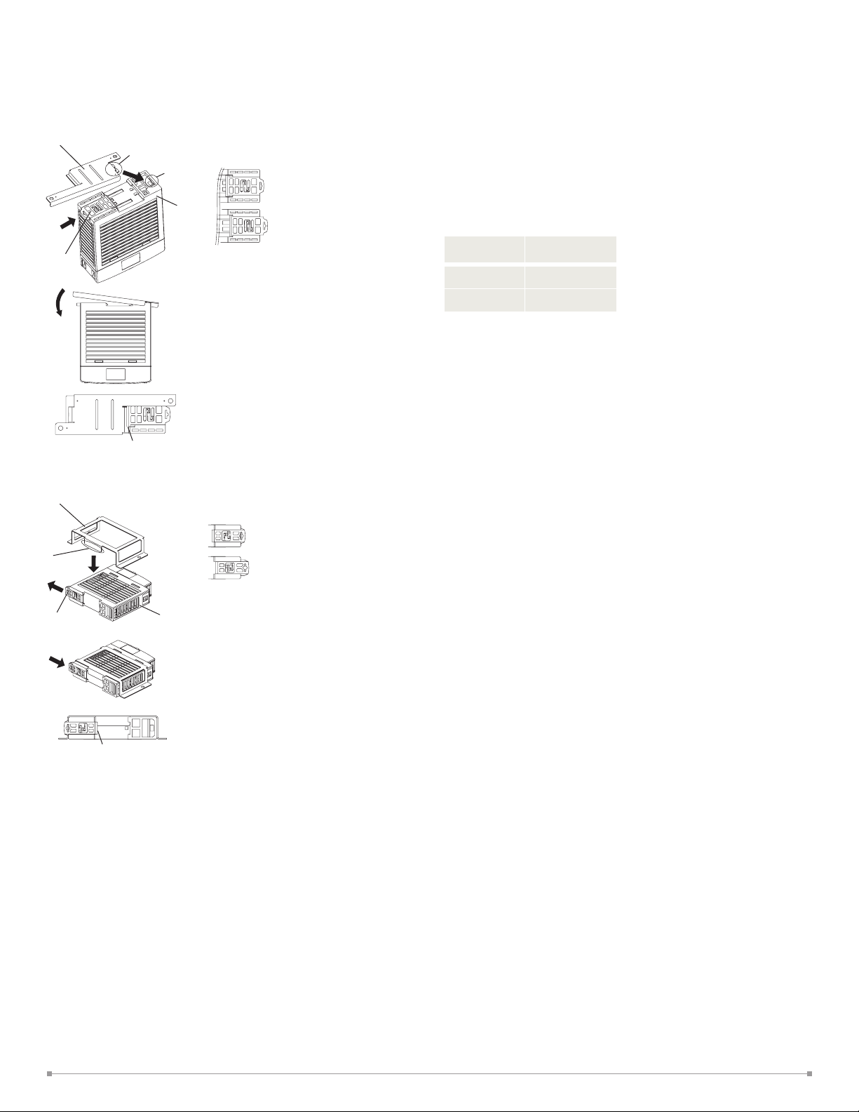
<Installing PS9Z-5R1 Panel Mounting Bracket>
<Installing PS9Z-5R2B Panel Mounting Bracket>
OPERATING INSTRUCTIONS
Installing a Panel Mounting Bracket
Panel Mounting Bracket (PS9Z-5R1)
Tab
Slot
Latch
LOCK
Push in the latch to LOCK
position.
Power
Supply
Install the tab on the panel
mounting bracket into the
slot on the power supply.
Install the brackets as
shown on the left.
Ensure that the panel
mounting bracket is locked
by the latch.
Panel Mounting Bracket (PS9Z-5R2B)
Tab
Latch
Power
Supply
Pull out the latch to
UNLOCK position.
LOCK
UNLOCK
Insert the tab on the panel
mounting bracket into the
slot on the power supply.
LOCK
UNLOCK
Overcurrent Protection
The output voltage drops automatically when an overcurrent flows due to an overload or short
circuit. Normal voltage is auto matically restored when the load returns to normal conditions.
Notes for Operation
• Output interruption may indicate blown fuses. Contact IDEC.
• The PS5R-V switching power supply contains an internal fuse for AC input. When using
DC input, install an exter nal fuse. To avoid blown fuses, select a fuse in consideration of
the rated current of the internal fuse.
Rated Current of Internal Fuses
Part Number
PS5R-VB/VC 2A
PS5R-VD/VF 4A
• Avoid overload and short-circuit for a long period of time, oth erwise the internal elements
may be damaged.
• DC input operation is not subject to safety standards.
Internal Fuse
Rated Current
Rust and Scratches on Metal parts
Bonded metal parts are used for the PS5R-V. Rust on the edge and scratches on the surfaces
may be developed depending on the storage condition, but the performance of the PS5R-V is not
affected.
Noise
Small acoustic noise inside the PS5R-V may be heard depending on the input voltage and load,
but the performance of the PS5R-V is not affected.
Push in the latch to LOCK
position.
LOCK
Ensure that the panel
mounting bracket is locked
by the latch.
Adjustment of Output Voltage
The output voltage can be adjusted within ±10% of the rated output voltage by using the
VR.ADJ control on the front. Turning the VR.ADJ clockwise increases the output voltage. Turning
the VR.ADJ counterclockwise decreases the output voltage.
6
(a)
L
N
(b)
AC
D
OPERATING INSTRUCTIONS
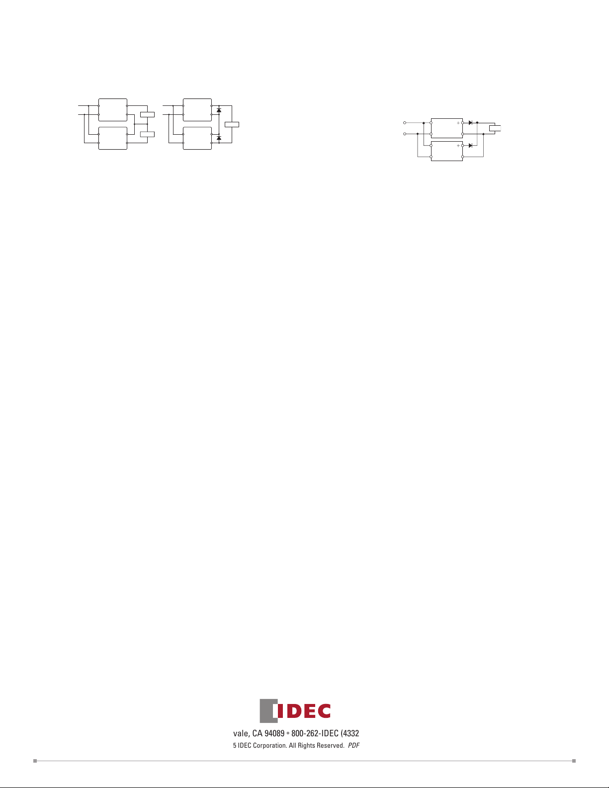
Series Operation
Series operation is allowed. Connect Schottky barrier diodes D as shown below. Select a
Schottky diode in consideration of the rated current. The diode’s reverse voltage must be higher
than the PS5R-V's output voltage.
L
L
N
LN+V
Load
Load
L
N
+V
–V
–V
N
LN+V
+V
D
–V
Load
D
–V
Parallel Operation
Parallel operation is not possible to increase the output capacity, because the internal elements and load may be damaged.
WARRANTY
Warranty
IDEC warranties the PS5R-V switching power supply for a period of five years from the date of
shipment.
Scope
IDEC agrees to repair or replace the PS5R-V switching power supply if the product has been
operated under the following conditions. The maximum value of output capacity is within the
range shown in “Operating Temperature vs.
Output Current on page 3.
1. Average operating temperature (ambient temperature of switching power supply) is 40°C
maximum.
2. The load is 80% maximum.
3. Input voltage is the rated input voltage.
4. Standard mounting style
Backup Operation
Backup operation is a connection method of two switching power supplies in parallel for emergency. Normally one switching power supply has a sufficient output. If one switching power
supply fails, another one operates to continue the output. Make sure that the sum of power
consumption by load and diode is not greater than the rated wattage (rated voltage × rated current) of one switching power supply.
IN
OUT
−
IN OUT
−
Select a diode in consideration of:
Diode's current must be more than double the PS5R-V's output current. Take heat dissipation
into consideration.
IDEC shall not be liable for other damages including consequential, contingent or incidental damages. Warranty does not apply if the PS5R-V switching power supply was subject to:
1. Inappropriate handling, or operation beyond specifications.
2. Modification or repair by other than IDEC.
3. Failure caused by other than the PS5R-V switching power supply.
4. Failure caused by natural disasters.
Load
D
IDEC Corporation • 1175 Elko Drive • Sunnyvale, CA 94089 • 800-262-IDEC (4332) • Fax: 408-745-5258 • www.IDEC.com/usa
©2015 IDEC Corporation. All Rights Reserved. PDF only
7
 Loading...