

Page 1
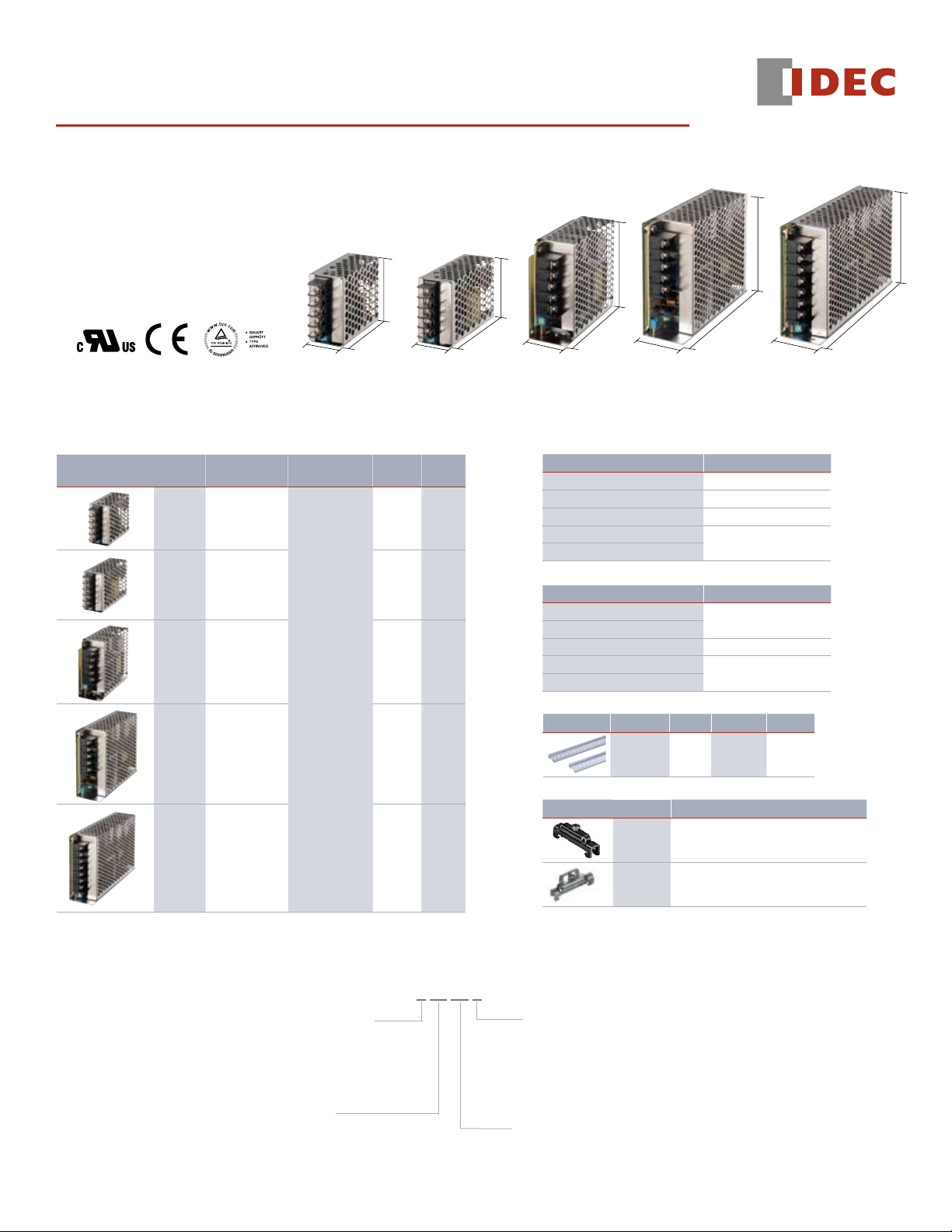
PS3X Series Switching Power Supplies
Features
Compact size•
Universal AC input voltage•
5V, 12V, and 24V DC outputs•
Available with mounting brackets for direct •
or DIN rail mounting
Overcurrent/overvoltage protection•
EMC, EN55022 Class B compliant•
UL/c-UL recognized, TUV•
Part Numbers
Power Supply
Apperance
Output
Capacity
15W
25W
50W
75W
28
PS3X-B (15W)
Part Number Input Voltage
PS3X-B05AFC
PS3X-B12AFC
PS3X-B24AFC
PS3X-C05AFC
PS3X-C12AFC
PS3X-C24AFC
PS3X-D12AFG
PS3X-D24AFG
100 to 240V AC
PS3X-Q05AFG
PS3X-Q12AFG
PS3X-Q24AFG
62
50.8
Output
Voltage
5V
12V
24V
5V
12V
24V
12V
24V
5V
12V
24V
28.5
PS3X-C (25W)
Output
Current
3.0A
1.3A
0.63A
5.0A
2.1A
1.1A
4.2A
2.2A
12.0A
6.0A
3.2A
50.8
79
35
PS3X-D (50W)
L-shaped Mounting Bracket (optional)
Applicable Power Supply Part Number
DIN-rail Mounting Bracket (optional)
Applicable Power Supply Part Number
DIN Rail
Appearance Part Number Length Material Weight (g)
End Clips
Appearance Part Number Description
82
99
PS3X-B PS9Z-3N3A
PS3X-C PS9Z-3N3B
PS3X-D PS9Z-3E3B
PS3X-Q
PS3X-E
PS3X-B
PS3X-C
PS3X-D PS9Z-3E4C
PS3X-Q
PS3X-E
BNDN1000 1000mm Aluminum 200
38
PS3X-Q (75W)
129
PS9Z-3N3E
PS9Z-3N4B
PS9Z-3E4D
95
38
PS3X-E (100W)
95
159
100W
PS3X-E05AFG
PS3X-E12AFG
PS3X-E24AFG
Part Number Configuration
PS3X - B 05 AF C
Output Capacity
B: 15W
C: 25W
D: 50W
Q: 75W
E: 100W
Output Voltage
05: 5V DC (15W, 25W, 75W, 100W)
12: 12V DC
24: 24V DC
5V
12V
24V
16.0A
8.5A
4.5A
Cover and Terminal Style
C: w/Standard cover,
Horizontal terminal block
(PS3X-B/C models)
G: w/Standard cover,
Vertical terminal block
(PS3X-D/Q/E models)
Input Voltage
AF: 100 to 240V AC
BNL5 small DIN rail end clip
medium DIN rail end clip (the BNL6 has a higher
BNL6
profile than BNL5)
Page 2
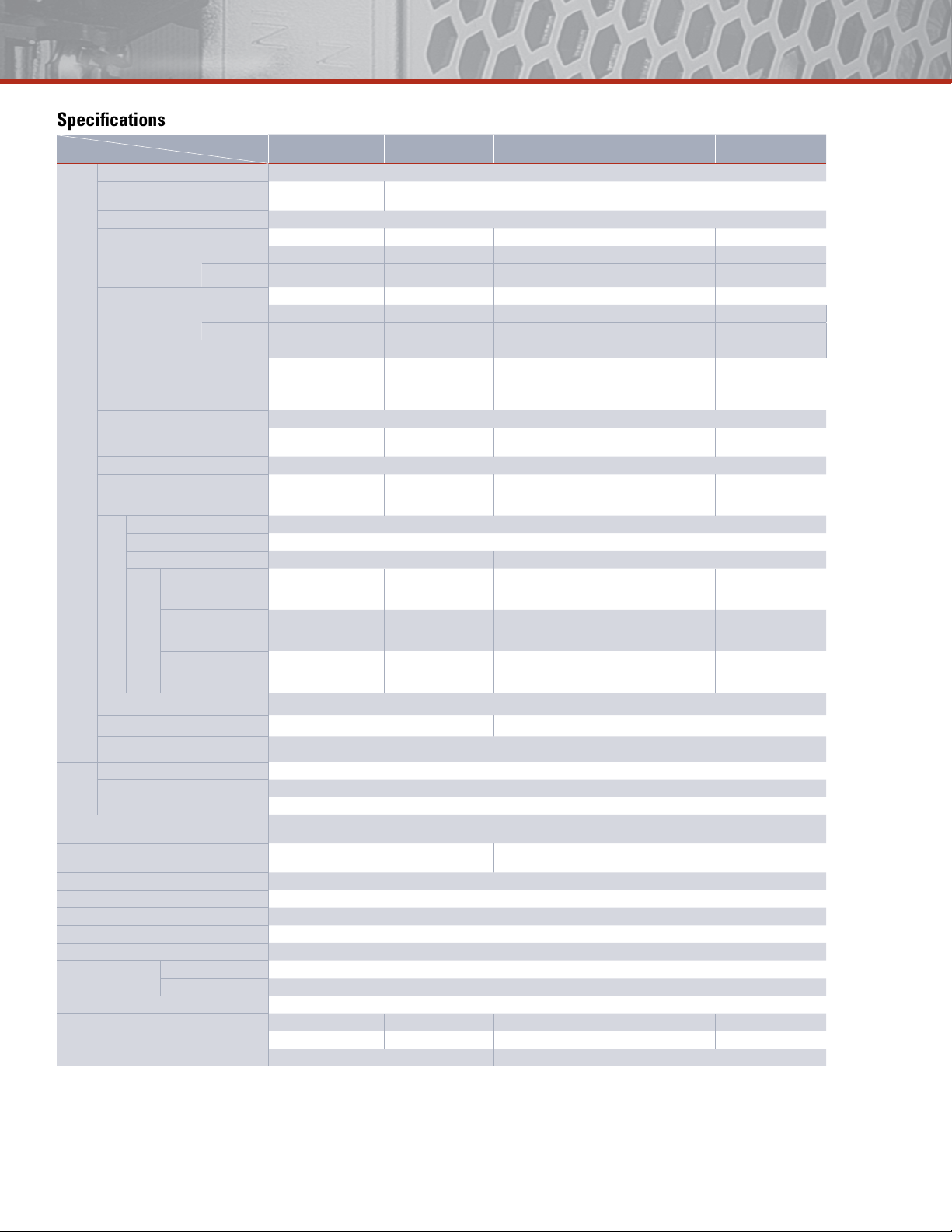
Specifications
Description
Power Supplies
[15W]
PS3X-B05/B12/B24
Rated Input Voltage 100 to 240V AC
Voltage Range (Note 1)
85 to 264V AC/
120 to 375V DC
Frequency 47 to 63 Hz
Input Current 0.5A max. 0.65A max. 1.3A max. 1.8A max. 2.5A max.
Input
Inrush Current
(Ta = –25°C,
ACV cold start)
at 115V AC 40A max. 30A max. 30A max. 30A max. 35A max.
at 230V AC 60A max. 50A max. 50A max. 50A max. 70A max.
Leakage Current 0.5mA max. 1.5mA max. 1.5mA max. 1.5mA max. 1.5mA max.
Efficiency (Typ.)
(230V AC at input/rated
output)
5V 77% 77% — 77% 77%
12V 81% 81% 81% 82% 81%
24V 82% 84% 84% 84% 84%
5V, 3A 5V, 5A — 5V, 12A 5V, 16A
Rated Voltage/Current
12V, 1.3A 12V, 2.1A 12V, 4.2A 12V, 6A 12V, 8.5A
24V, 0.63A 24V, 1.1A 24V, 2.2A 24V, 3.2A 24V, 4.5A
Adjustable Voltage Range ±10%
Output Holding Time
13 ms typ. (100V AC)
60 ms minimum (230V AC)
Start Time 1000 ms max. (230V AC input, rated output)
50 ms max.
Rise Time
(230V AC input, rated
output)
Output
Input Fluctuation 0.5% max.
Overvoltage Fluctuation 5V: ±2% max. 12V, 24V: ±1% max.
Temperature Fluctuation 0.04% / °C max. (–20 to +50°C) 0.04% / °C max. (–10 to +45°C)
5V: 200mV max.
12V/24V: 200mV max.
5V: 160mV max.
12V/24V: 200mV max.
5V: 100mV max.
12V/24V: 150mV max.
Regulation
Ripple
–20 to –10°C
–10 to 0°C
(including noise)
PS3X-B, C: 0 to +50°C
PS3X-D, Q, E: 0 to +45°C
Overcurrent Protection 105% min. (auto reset) (Note 2)
Overvoltage Protection Voltage limitation at 115% min. Intermittent operation or output off at 115% min. (Note 3)
Functions
Operation Indicator green LED
Supplementary
Between input and output terminals 3000V AC, 1 minute
Between input and ground terminals 2000V AC, 1 minute
Strength
Dielectric
Between output and ground terminals 500V DC, 1 minute
Insulation Resistance
Operating Temperature
–20 to +70°C
(no freezing, see output derating)
Operating Humidity 20 to 85% RH (no condensation)
Storage Temperature –40 to +85°C (no freezing)
Storage Humidity 10 to 95% RH (no condensation)
Vibration Resistance 10 to 55 Hz, 20m/s
Shock Resistance 200m/s
EMC
EMI EN55022 Class B
EMS EN55024
Safety Standards IEC/EN60950-1, UL60950-1, CSA C22.2 No. 60950-1
Dimensions (H × W × D) (mm) 50.8H × 28W × 62D 50.8H × 28.5W × 79D 82H × 35W × 99D 95H × 38W × 129D 95H × 38W × 159D
Weight (approx.) 130g 180g 340g 500g 700g
Terminal Screw M3 M3.5
Note 1: See “Output Current vs. Input Voltage” characteristics next page. Not subject to safety standards. When using DC input, connect a fuse to the input terminal for DC input protection.
Note 2: Overload for 30 seconds or longer may damage the internal elements.
Note 3: One minute after the output has been turned off, turn on the AC input again.
[25W]
PS3X-C05/C12/C24
[50W]
PS3X-D12/D24
[75W]
PS3X-Q05/Q12/Q24
88 to 264V AC / 125 to 375V DC
10 ms typ. (100V AC)
60 ms minimum (230V AC)
30 ms max.
(230V AC input, rated
output)
23 ms typ. (100V AC)
60 ms minimum (230V AC)
30 ms max.
(230V AC input, rated
output)
14 ms typ. (100V AC)
60 ms minimum (230V AC)
30 ms max.
(230V AC input, rated
output)
5V: 140mV max.
12V: 240mV max.
– – –
24V: 300mV max.
5V: 140mV max.
12V: 240mV max.
24V: 300mV max.
5V: 70mV max.
12V: 120mV max.
24V: 150mV max.
12V: 240mV max.
24V: 300mV max.
12V: 120mV max.
24V: 150mV max.
5V: 140mV max.
12V: 240mV max.
24V: 300mV max.
5V: 70mV max.
12V: 120mV max.
24V: 150mV max.
100MΩ minimum, 500V DC megger
(between input and output terminals, between input and ground terminals)
–10 to +70°C
(no freezing, see output derating)
2
constant, 2 hours each in 3 axes
2
, 1 shock each in 3 axes
[100W]
PS3X-E05/E12/E24
17 ms typ. (100V AC)
80 ms minimum (230V AC)
30 ms max.
(230V AC input, rated
output)
5V: 160mV max.
12V: 240mV max.
24V: 300mV max.
5V: 100mV max.
12V: 120mV max.
24V: 150mV max.
Page 3

Characteristics
-100 10 20 30 40 50 60 70
0
10
20
30
40
37.5
50
60
70
80
90
100
-10 010203040506070
0
10
20
30
40
50
60
70
80
90
100
-30
-20
-100 10 20 30 40 50 60 70
0
10
20
30
40
50
60
70
80
90
100
Output Current (%)
Operating Temperature (°C) Operating Temperature (°C) Operating Temperature (°C)
Output Current (%)
Output Current (%)
PS3X-B: 85
PS3X-C: 88
100
100
264
264
0
10
20
30
40
50
60
70
80
90
100
88 100 264
0
10
20
30
40
50
60
70
80
90
100
88
176
132
264
0
10
20
30
40
50
60
70
80
90
100
Output Current (%)
Input Voltage (VAC)Input Voltage (VAC)Input Voltage (VAC)
Output Current (%)
Output Current (%)
Up
Mounting A
(standard)
Mounting B
0 100 105
0
100
Output Voltage (%)
Intermittent Operation
Output Current (%)
Operating Temperature vs. Output Current (Derating Curves)
Conditions: Natural air cooling (operating temperature is the temperature around the power supply)
PS3X-B/C PS3X-D/Q/E
Output Current vs. Input Voltage (TA = 25°C)
PS3X-B/C PS3X-D/Q/E
Overcurrent Protection Characteristics
PS3X
Operating Temperature by Safety Standards
Power Supplies
PS3X-B05, -B12, -B24
PS3X-C05, -C12, -C24
PS3X-D12, -D24
PS3X-Q05, -Q12, -Q24
PS3X-E05, -E12, -E24
Note: Observe the derating curves when operating PS3X power supplies.
UL/EN60950-1
Mounting A, B
50°C
45°C
800.262.4332
Page 4

Dimensions (mm)
39.1
11.4
62.0
15.1
28
39.1
8.25
25.25
50.8
5-M3
(Terminal Screw)
76.0
Output Voltage
Adjustment
LED
Terminal Cover
7.62
(Terminal Centers)
2-M3 (Depth 2.5
to 4.0 mm max.)
2-M3 (Depth 2.5
to 4.0 mm max.)
79.0
65.0
14.5
28.5
11.0
55.0
25.4
50.8
13.0
91.9
5-M3
(Terminal Screw)
Terminal Cover
7.62
(Terminal Centers)
Output Voltage
Adjustment
LED
2-M3 (Depth 2.5
to 4.0 mm max.)
2-M3 (Depth 2.5
to 4.0 mm max.)
74.018.0
17.5
35.0
99.0
55.020.5
82.0
45.5
99.7
LED
2-M3
(Depth 2.5 to
4.0 mm max.)
5-M3
(Terminal Screw)
Output Voltage
Adjustment
Terminal
Cover
9.5
(Terminal Centers)
2-M3 (Depth 2.5
to 4.0 mm max.)
129.0
18.0
77.0
10.5
38.0
19.5
32.0
78.0
33.034.0
95.0
129.3
)
2-M3 (Depth 2.5
to 4.0 mm max.)
3-M3
(Depth 2.5 to
4.0 mm max.)
5-M3
(Terminal Screw)
LED
Output Voltage
Adjustment
Terminal
Cover
9.5
(Terminal Centers)
78.024.0
32.0
95.0
162.6
159.0
38.0
18.0
118.0
22.0
19.0
10.0
3-M3
(Depth 2.5 to
4.0 mm max.)
7-M3.5
(Terminal Screw)
LED
Output Voltage
Adjustment
Terminal
Cover
9.5
(Terminal Centers)
2-M3 (Depth 2.5
to 4.0 mm max.)
LED
V.ADJ
L
N
−V
+V
LED
V.ADJ
L
N
–V
+V
LED
V.ADJ
L
N
−V
+V
PS3X-B PS3X-C PS3X-D
PS3X-Q PS3X-E
Terminal Markings
PS3X-B/C PS3X-D/Q PS3X-E
Marking Name Description
Accepts a wide range of voltage and
L, N AC Input Terminal
frequency. Polarity does not matter
when using DC input.
Ground Terminal
Be sure to connect this terminal to a
proper ground.
+V, –V DC Output Terminals Positive and negative output terminals
V.ADJ Output Voltage Adjustment
LED Power status
Allows adjustment within ±10%. Turning
clockwise increases the output voltage.
Illuminates (green) when input power is
applied.
Page 5

L-shaped Mounting Bracket
20.0
20.03.5
10.0 6.5
27.0
2.0
2-ø3.5 holes
27.0
72.0
14
16.539.1
4126
4-ø3.5 holes
6.517.5
28.0
22.04.0
2.3
13.5
65.0
83.5
±0.5
14.0
30.0
4-ø3.5 holes
4-ø3.5 holes
74.0
±0.3
80.0
±0.3
18.0
103.0
13.5
31.0
15.5
2.3
17.5
28.0
4.5
22.5
6.5
ø3.5 holes
3.5 × 4.5
oblong hole
3-ø3.5 holes
3-ø4.5 holes
4-ø4.5 holes
4-ø3.5 holes
2.0
7.5
20.0
±0.2
10.0
28.0
15.0
7.0
10.0
10.0
34.5
12.5
100.0
±0.3
157.5
42.5
25.0
118.0
77.0
18.0
2-C2.0
H3
H135H2
L1
L2
L3
Up
Mounting A
(standard)
Mounting B
Chassis
2.5 to 4 mm
Mounting
Panel
Mounting
Screw
PS9Z-3N3A (for 15W)
PS9Z-3E3B (for 50W)
DIN-rail Mounting Bracket
PS9Z-3N3B (for 25W)
PS9Z-3N3E (for 75W/100W)
Part Number Applicable Power Supply L1 L2 L3 H1 H2 H3
PS9Z-3N4B
PS9Z-3E4C PS3X-D 136 117* 35 5.2 20.5 82
PS9Z-3E4D
* Note that L2 is shorter than L1.
PS3X-B 95 105.5 35 5.2 20.5 50.8
PS3X-C 95 113 35 5.2 20.5 50.8
PS3X-Q 188 141* 39.5 5.2 19.7 95
PS3X-E 188 173* 39.5 5.2 19.7 95
Installation Notes
When mounting the PS3X 1.
switching power supply, see
the figure on the right.
See dimension drawings for mounting 2.
hole layouts.
Use M3 screws for mounting. 3.
Choose screws that protrude 2.5 to
4mm from the surface of the
switching power supply.
Do not cover the openings of the 4.
switching power supply. Ensure proper
heat dissipation by convection.
Maintain a minimum of 20mm clearance around the power supply.5.
When derating of the output does not work, provide forced air-cooling.6.
Make sure to wire the ground terminal correctly.7.
For wiring, use wires with heat resistance of 60°C or higher. 8.
Use copper wire.
Recommended tightening torque of terminal screws: 0.8 N·m9.
Adjustment of Output Voltage
The output voltage can be adjusted within ±10% of the rated output voltage
by using the V.ADJ control. Turning the V.ADJ clockwise increases the output
voltage. Turning counterclockwise decreases the output voltage. Note that
overvoltage protection may work when increasing the output voltage.
Overcurrent Protection
The output voltage drops automatically when an overcurrent flows, resulting in
intermittent operation. Normal voltage is automatically restored when the load
returns to normal conditions. However, overcurrent for a prolonged period of
time or short-circuit causes the internal elements to deteriorate or break down.
Overvoltage Protection
PS3X-B/C: Voltage limit and auto-recovery method. The switching power
supplies operate normally when voltage returns to normal.
PS3X-D/Q/E: The output is turned off when an overvoltage is applied. When the
output voltage has dropped due to an overvoltage, turn the input off, and after
one minute, turn the input on again.
Series Operation
When connecting two switching power supplies in a series, insert a Schottky
diode to each output.
Parallel Operation
Parallel operation is not possible.
Insulation/Dielectric Test
When performing an insulation/dielectric test, short the input (between AC)
and output (between + and –). Do not apply or interrupt the voltage suddenly,
otherwise surge voltage may be generated and the power supply may be
damaged.
Page 6

Safety Precautions
Do not use switching power supplies with equipment where failure or •
inadvertent operation may harm anyone, such as medical, aerospace, railway,
nuclear, etc. PS3X switching power supplies are designed for use in general
electric equipment such as office, communication, measuring, and industrial
electric devices.
Do not disassemble, repair, or modify the power supplies, otherwise electric •
shock, fire, or failure may occur.
Do not install the switching power supply in places where someone will •
touch it when input voltage is applied. Do not touch the switching power
supply while input voltage is applied and right after the power is turned off,
because high temperature and high voltage may cause burns and electric
shocks.
Do not short circuit the output terminals or output lead wires, otherwise fire •
or damage may occur.
Provide the final product with protection against failure or damage that may •
be caused by malfunction of the switching power supply. Damaged switching
power supply may cause overvoltage on the output terminals, or may cause
voltage drop.
Turn off power before wiring. Also, make sure to wire correctly. Improper •
wiring may cause electric fire or damage.
Do not use switching power supplies to charge rechargeable batteries.•
Make sure that the input voltage does not exceed the rating. Note polarity •
of input and output terminals and wire correctly. Incorrect wiring may cause
blown fuses (AC input power), smoke or fire.
Do not touch the inside of the switching power supply, and make sure that •
foreign objects do not enter the switching power supply, otherwise an
accident or failure may occur.
Observe the temperature derating curves. Operating temperature refers to the •
temperature around the lower part of the switching power supply. Failure to
observe the derating curves could result in an internal temperature rise and
possible failure of the switching power supply.
The fuse inside the switching power supply is for AC input. When using with •
DC input, install an external fuse.
Do not set the V. ADJ control over the setting range, otherwise performance •
deterioration or failure may occur.
When failure or error occurs, shut down the input to the switching power •
supply, and contact IDEC.
Do not use or store the switching power supply in a place subject to extreme •
vibration or shocks, otherwise failure will result.
Do not use the switching power supply where it is subject to or near:•
Direct sunlight, heat or high temperatures Metal powder, oil, chemicals or hydrogen sulfide Highly humid areas, such as a basement or conservatory Inside freezers or refrigerators, near cooler exhaust, or other cold -
environments
Lightweight and compact in size•
Wide power range: 10W-240W•
Universal input: •
10W to 90W: 85-264V AC/100-370V DC
120W and 240W: 85-264V AC/100-350V DC
Power Factor Correction for 60W to 240W •
(EN61000-3-2)
Meets SEMI F47 Sag Immunity (120W & 240W only)•
Approved for Class 1, Div. 2 Hazardous Locations•
Overcurrent protection, auto-reset•
Overvoltage protection, shut down•
Spring-up screw terminal type, IP20•
DIN rail or panel surface mount•
Approvals: •
CE Marked
TÜV
c-UL, UL508
UL1310 (PS5R-SB, -SC, -SD)
UL/ANSI 12.12.01-2007 (Hazardous locations)
EN50178:1997
LVD: EN60950:2000
EMC: Directive EN61204-3:2000 (EMI: Class B, EMS: Industrial)
PS5R Slim Line models give you all the power of a traditional power supply in only half
the space. The 10W and 15W are only 22.5mm wide, the 30W and 60W are 36mm
wide, and the 90W is 46mm wide. The 120W unit has a width of only 50mm while the
240W is 80mm wide. They also come with all the convenient features you’ve come to
expect from IDEC.
Utilize them in tight spaces or save valuable DIN Rail space while still filling your
requirements for power. With all the available choices, it’s easy to find the one that’s
right for your application!
 Loading...