

Page 1
EM345-0
Phone: 800.894.0412 - Fax: 888.723.4773 - Web: www.clrwtr.com - Email: info@clrwtr.com
OPENNET CONTROLLER
Page 2
SAFETY PRECAUTIONS
Warning
Warning notices are used to emphasize that improper operation may cause
severe personal injury or death.
Caution
Caution notices are used where inattention might cause personal injury or
damage to equipment.
Phone: 800.894.0412 - Fax: 888.723.4773 - Web: www.clrwtr.com - Email: info@clrwtr.com
• Read this user’s manual to make sure of correct operation before starting installation, wiring, operation, maintenance, and
inspection of the OpenNet Controller.
• All OpenNet Controller modules are manufactured under IDEC’s rigorous quality control system, but users must add a
backup or failsafe provision to the control system using the OpenNet Controller in applications where heavy damage or
personal injury may be caused in case the OpenNet Controller should fail.
• In this user’s manual, safety precautions are categorized in order of importance to Warning and Caution:
• Turn off the power to the OpenNet Controller before starting installation, removal, wiring, maintenance, and inspection of
the OpenNet Controller. Failure to turn power off may cause electrical shocks or fire hazard.
• Special expertise is required to install, wire, program, and operate the OpenNet Controller. People without such expertise
must not use the
• Emergency stop and interlocking circuits must be configured outside the
inside the OpenNet Controller, failure of the OpenNet Controller may cause disorder of the control system, damage, or
accidents.
• Install the OpenNet Controller according to instructions described in this user’s manual. Improper installation will result in
falling, failure, or malfunction of the OpenNet Controller.
• The OpenNet Controller is designed for installation in a cabinet. Do not install the OpenNet Controller outside a cabinet.
• Install the OpenNet Controller in environments described in this user’s manual. If the OpenNet Controller is used in places
where the OpenNet Controller is subjected to high-temperature, high-humidity, condensation, corrosive gases, excessive
vibrations, and excessive shocks, then electrical shocks, fire hazard, or malfunction will result.
• The environment for using the OpenNet Controller is “Pollution degree 2.” Use the OpenNet Controller in environments of
pollution degree 2 (according to IEC 60664-1).
• The DC power applicable to the OpenNet Controller is “PS2” type (according to EN 61131).
• Prevent the OpenNet Controller from falling while moving or transporting the OpenNet Controller, otherwise damage or
malfunction of the OpenNet Controller will result.
• Prevent metal fragments and pieces of wire from dropping inside the OpenNet Controller housing. Put a cov er on the Open-
Net Controller
or malfunction.
• Use a power supply of the rated value. Use of a wrong power supply may cause fire hazard.
• Use wires of a proper size to meet voltage and current requirements. Tighten terminal screws to a proper tightening torque
of 0.5 to 0.6 N·m.
• Use an IEC 60127-approved fuse on the power line outside the OpenNet Controller. This is required when equipment con-
taining the
• Use an IEC 60127-approved fuse on the output circuit. This is required when equipment containing the
is destined for Europe.
• Use an EU-approved circuit breaker. This is required when equipment containing the
Europe.
• Make sure of safety before starting and stopping the
outputs on or off. Incorrect operation on the OpenNet Controller may cause machine damage or accidents.
• If relays or transistors in the OpenNet Controller output modules should fail, outputs may remain on or off. For output signals which may cause heavy accidents, provide a monitor circuit outside the OpenNet Controller.
• Do not connect to the ground directly from the OpenNet Controller. Connect a protective ground to the cabinet containing
OpenNet Controller using an M4 or larger screw. This is required when equipment containing the OpenNet Controller is
destined for Europe.
• Do not disassemble, repair, or modify the OpenNet Controller modules.
• Dispose of the battery in the
tions. When storing or disposing of the battery, use a proper container prepared for this purpose. This is required when
equipment containing the OpenNet Controller is destined for Europe.
• When disposing of the
OpenNet Controller.
OpenNet Controller. If such a circuit is configured
modules during installation and wiring. Ingress of such fragments and chips may cause fire hazard, damage,
OpenNet Controller is destined for Europe.
OpenNet Controller
OpenNet Controller is destined for
OpenNet Controller or when operating the OpenNet Controller to force
OpenNet Controller modules when the battery is dead in accordance with pertaining regula-
OpenNet Controller, do so as an industrial waste.
OPENNET CONTROLLER USER’S MANUAL PREFACE-1
Page 3

About This Manual
Phone: 800.894.0412 - Fax: 888.723.4773 - Web: www.clrwtr.com - Email: info@clrwtr.com
This user’s manual primarily describes entire functions of the OpenNet Controller CPU modules, digital I/O modules, analog I/O modules. Also included are powerful communications of the OpenNet Controller.
CHAPTER 1: GENERAL INFORMATION
General information about the OpenNet Controller, features, brief description on special functions, and various system
setup configurations for communication.
CHAPTER 2: MODULE SPECIFICATIONS
Specifications of CPU, digital and analog I/O, expansion power supply, remote I/O master, OpenNet interface modules.
CHAPTER 3: INSTALLATION AND WIRING
Methods and precautions for installing and wiring OpenNet Controller modules.
CHAPTER 4: OPERATION BASICS
General information about setting up the basic OpenNet Controller system for programming, starting and stopping Open-
Net Controller
toring the OpenNet Controller operation.
CHAPTER 5: SPECIAL FUNCTIONS
Stop/reset inputs, run/stop selection at memory backup error, keep designation for internal relays, shift registers, counters,
and data registers. Also included are module ID selection and run/stop operation upon disparity, input filter, catch input,
high-speed counter, key matrix input, and user program read/write protection.
CHAPTER 6: ALLOCATION NUMBERS
Allocation numbers available for the OpenNet Controller CPU module to program basic and advanced instructions. Special internal relays and special data registers are also described.
operation, and simple operating procedures from creating a user program using WindLDR on a PC to moni-
CHAPTER 7: BASIC INSTRUCTIONS
Programming of the basic instructions, available operands, and sample programs.
CHAPTER 8: ADVANCED INSTRUCTIONS
General rules of using advanced instructions, terms, data types, and formats used for advanced instructions.
CHAPTER 9 THROUGH CHAPTER 20:
Detailed descriptions on advanced instructions grouped into 12 chapters.
CHAPTER 21 THROUGH CHAPTER 26:
Various communication functions such as data link, computer link, modem mode, remote I/O system, Devicenet slave
module, and LONWORKS interface module.
CHAPTER 27: TROUBLESHOOTING
Procedures to determine the cause of trouble and actions to be taken when any trouble occurs while operating the OpenNet
Controller
.
APPENDIX
Additional information about execution times for instructions, I/O delay time, and OpenNet Controller type list.
INDEX
Alphabetical listing of key words.
IMPORTANT INFORMATION
Under no circumstances shall IDEC Corporation be held liable or responsible for indirect or consequential damages resulting
from the use of or the application of IDEC PLC components, individually or in combination with other equipment.
All persons using these components must be willing to accept responsibility for choosing the correct component to suit their application and for choosing an application appropriate for the component, individually or in combination with other equipment.
All diagrams and examples in this manual are for illustrative purposes only. In no way does including these diagrams and
examples in this manual constitute a guarantee as to their suitability for any specific application. To test and approve all programs, prior to installation, is the responsibility of the end user.
PREFACE-2 OPENNET CONTROLLER USER’S MANUAL
Page 4

TABLE OF CONTENTS
Phone: 800.894.0412 - Fax: 888.723.4773 - Web: www.clrwtr.com - Email: info@clrwtr.com
HAPTER 1: GENERAL INFORMATION
C
About the OpenNet Controller . . . . . . . . . . . . . . . . . . . . . . . . . . . . . . . . . . . . . . . . . . . 1-1
Features . . . . . . . . . . . . . . . . . . . . . . . . . . . . . . . . . . . . . . . . . . . . . . . . . . . . . . . . . . 1-1
Special Functions . . . . . . . . . . . . . . . . . . . . . . . . . . . . . . . . . . . . . . . . . . . . . . . . . . . . 1-2
System Setup . . . . . . . . . . . . . . . . . . . . . . . . . . . . . . . . . . . . . . . . . . . . . . . . . . . . . . 1-3
HAPTER 2: MODULE SPECIFICATIONS
C
CPU Module . . . . . . . . . . . . . . . . . . . . . . . . . . . . . . . . . . . . . . . . . . . . . . . . . . . . . . . . 2-1
Input Module . . . . . . . . . . . . . . . . . . . . . . . . . . . . . . . . . . . . . . . . . . . . . . . . . . . . . . . 2-7
Output Module . . . . . . . . . . . . . . . . . . . . . . . . . . . . . . . . . . . . . . . . . . . . . . . . . . . . . 2-16
Analog Input Module (A/D Converter) . . . . . . . . . . . . . . . . . . . . . . . . . . . . . . . . . . . . . 2-28
Analog Output Module (D/A Converter) . . . . . . . . . . . . . . . . . . . . . . . . . . . . . . . . . . . . 2-31
Expansion Power Supply Module . . . . . . . . . . . . . . . . . . . . . . . . . . . . . . . . . . . . . . . . 2-34
Remote I/O Master Module . . . . . . . . . . . . . . . . . . . . . . . . . . . . . . . . . . . . . . . . . . . . 2-36
DeviceNet Slave Module . . . . . . . . . . . . . . . . . . . . . . . . . . . . . . . . . . . . . . . . . . . . . . 2-38
LonWorks Interface Module . . . . . . . . . . . . . . . . . . . . . . . . . . . . . . . . . . . . . . . . . . . . 2-39
Dimensions . . . . . . . . . . . . . . . . . . . . . . . . . . . . . . . . . . . . . . . . . . . . . . . . . . . . . . . 2-40
HAPTER 3: INSTALLATION AND WIRING
C
Installation Location . . . . . . . . . . . . . . . . . . . . . . . . . . . . . . . . . . . . . . . . . . . . . . . . . . 3-1
Assembling Modules . . . . . . . . . . . . . . . . . . . . . . . . . . . . . . . . . . . . . . . . . . . . . . . . . . 3-2
Disassembling Modules . . . . . . . . . . . . . . . . . . . . . . . . . . . . . . . . . . . . . . . . . . . . . . . 3-3
Mounting on DIN Rail . . . . . . . . . . . . . . . . . . . . . . . . . . . . . . . . . . . . . . . . . . . . . . . . . 3-3
Removing from DIN Rail . . . . . . . . . . . . . . . . . . . . . . . . . . . . . . . . . . . . . . . . . . . . . . . 3-3
Installation in Control Panel . . . . . . . . . . . . . . . . . . . . . . . . . . . . . . . . . . . . . . . . . . . . . 3-4
Mounting Direction . . . . . . . . . . . . . . . . . . . . . . . . . . . . . . . . . . . . . . . . . . . . . . . . . . . 3-4
Input Wiring . . . . . . . . . . . . . . . . . . . . . . . . . . . . . . . . . . . . . . . . . . . . . . . . . . . . . . . . 3-5
Output Wiring . . . . . . . . . . . . . . . . . . . . . . . . . . . . . . . . . . . . . . . . . . . . . . . . . . . . . . . 3-6
Data Link Wiring . . . . . . . . . . . . . . . . . . . . . . . . . . . . . . . . . . . . . . . . . . . . . . . . . . . . . 3-7
Analog Input/Output Wiring . . . . . . . . . . . . . . . . . . . . . . . . . . . . . . . . . . . . . . . . . . . . . 3-8
Power Supply . . . . . . . . . . . . . . . . . . . . . . . . . . . . . . . . . . . . . . . . . . . . . . . . . . . . . . . 3-9
Terminal Connection . . . . . . . . . . . . . . . . . . . . . . . . . . . . . . . . . . . . . . . . . . . . . . . . . 3-10
HAPTER 4: OPERATION BASICS
C
Connecting OpenNet Controller to PC (1:1 Computer Link System) . . . . . . . . . . . . . . . . . 4-1
Start/Stop Operation . . . . . . . . . . . . . . . . . . . . . . . . . . . . . . . . . . . . . . . . . . . . . . . . . 4-2
Simple Operation . . . . . . . . . . . . . . . . . . . . . . . . . . . . . . . . . . . . . . . . . . . . . . . . . . . . 4-4
HAPTER 5: SPECIAL FUNCTIONS
C
Stop Input and Reset Input . . . . . . . . . . . . . . . . . . . . . . . . . . . . . . . . . . . . . . . . . . . . . 5-1
Run/Stop Selection at Memory Backup Error . . . . . . . . . . . . . . . . . . . . . . . . . . . . . . . . 5-2
Keep Designation for Internal Relays, Shift Registers, Counters, and Data Registers . . . . 5-3
Module ID Selection and Run/Stop Operation upon Disparity . . . . . . . . . . . . . . . . . . . . . 5-5
Input Filter . . . . . . . . . . . . . . . . . . . . . . . . . . . . . . . . . . . . . . . . . . . . . . . . . . . . . . . . . 5-6
Catch Input . . . . . . . . . . . . . . . . . . . . . . . . . . . . . . . . . . . . . . . . . . . . . . . . . . . . . . . . 5-7
High-speed Counter . . . . . . . . . . . . . . . . . . . . . . . . . . . . . . . . . . . . . . . . . . . . . . . . . . 5-9
Key Matrix Input . . . . . . . . . . . . . . . . . . . . . . . . . . . . . . . . . . . . . . . . . . . . . . . . . . . . 5-16
User Program Protection . . . . . . . . . . . . . . . . . . . . . . . . . . . . . . . . . . . . . . . . . . . . . . 5-18
Memory Card . . . . . . . . . . . . . . . . . . . . . . . . . . . . . . . . . . . . . . . . . . . . . . . . . . . . . . 5-19
Constant Scan Time . . . . . . . . . . . . . . . . . . . . . . . . . . . . . . . . . . . . . . . . . . . . . . . . . 5-20
OPENNET CONTROLLER USER’S MANUAL i
Page 5

TABLE OF CONTENTS
Phone: 800.894.0412 - Fax: 888.723.4773 - Web: www.clrwtr.com - Email: info@clrwtr.com
HAPTER 6: ALLOCATION NUMBERS
C
Operand Allocation Numbers . . . . . . . . . . . . . . . . . . . . . . . . . . . . . . . . . . . . . . . . . . . . 6-2
Operand Allocation Numbers for Functional Modules . . . . . . . . . . . . . . . . . . . . . . . . . . . 6-4
Operand Allocation Numbers for Master Module . . . . . . . . . . . . . . . . . . . . . . . . . . . . . . 6-4
Operand Allocation Numbers for Data Link Master Station . . . . . . . . . . . . . . . . . . . . . . . 6-5
Operand Allocation Numbers for Data Link Slave Station . . . . . . . . . . . . . . . . . . . . . . . . 6-5
Special Internal Relay Allocation Numbers . . . . . . . . . . . . . . . . . . . . . . . . . . . . . . . . . . . 6-6
Special Data Registers . . . . . . . . . . . . . . . . . . . . . . . . . . . . . . . . . . . . . . . . . . . . . . . 6-12
Digital I/O Module Operands . . . . . . . . . . . . . . . . . . . . . . . . . . . . . . . . . . . . . . . . . . . 6-18
Functional Module Operands . . . . . . . . . . . . . . . . . . . . . . . . . . . . . . . . . . . . . . . . . . . 6-18
Bit Designation of Link Register . . . . . . . . . . . . . . . . . . . . . . . . . . . . . . . . . . . . . . . . . 6-19
HAPTER 7: BASIC INSTRUCTIONS
C
Basic Instruction List . . . . . . . . . . . . . . . . . . . . . . . . . . . . . . . . . . . . . . . . . . . . . . . . . . 7-1
LOD (Load) and LODN (Load Not) . . . . . . . . . . . . . . . . . . . . . . . . . . . . . . . . . . . . . . . . . 7-2
OUT (Output) and OUTN (Output Not) . . . . . . . . . . . . . . . . . . . . . . . . . . . . . . . . . . . . . . . 7-2
SET and RST (Reset) . . . . . . . . . . . . . . . . . . . . . . . . . . . . . . . . . . . . . . . . . . . . . . . . . . 7-3
AND and ANDN (And Not) . . . . . . . . . . . . . . . . . . . . . . . . . . . . . . . . . . . . . . . . . . . . . . . 7-4
OR and ORN (Or Not) . . . . . . . . . . . . . . . . . . . . . . . . . . . . . . . . . . . . . . . . . . . . . . . . . . 7-4
AND LOD (Load) . . . . . . . . . . . . . . . . . . . . . . . . . . . . . . . . . . . . . . . . . . . . . . . . . . . . . 7-5
OR LOD (Load) . . . . . . . . . . . . . . . . . . . . . . . . . . . . . . . . . . . . . . . . . . . . . . . . . . . . . . 7-5
BPS (Bit Push), BRD (Bit Read), and BPP (Bit Pop) . . . . . . . . . . . . . . . . . . . . . . . . . . . . . 7-6
TML, TIM, TMH, and TMS (Timer) . . . . . . . . . . . . . . . . . . . . . . . . . . . . . . . . . . . . . . . . . 7-8
CNT, CDP, and CUD (Counter) . . . . . . . . . . . . . . . . . . . . . . . . . . . . . . . . . . . . . . . . . . 7-11
CC= and CC≥ (Counter Comparison) . . . . . . . . . . . . . . . . . . . . . . . . . . . . . . . . . . . . . . 7-14
TC= and TC≥ (Timer Comparison) . . . . . . . . . . . . . . . . . . . . . . . . . . . . . . . . . . . . . . . . 7-16
DC= and DC≥ (Data Register Comparison) . . . . . . . . . . . . . . . . . . . . . . . . . . . . . . . . . . 7-18
SFR and SFRN (Forward and Reverse Shift Register) . . . . . . . . . . . . . . . . . . . . . . . . . . 7-20
SOTU and SOTD (Single Output Up and Down) . . . . . . . . . . . . . . . . . . . . . . . . . . . . . . . 7-24
MCS and MCR (Master Control Set and Reset) . . . . . . . . . . . . . . . . . . . . . . . . . . . . . . 7-25
JMP (Jump) and JEND (Jump End) . . . . . . . . . . . . . . . . . . . . . . . . . . . . . . . . . . . . . . . . 7-27
END . . . . . . . . . . . . . . . . . . . . . . . . . . . . . . . . . . . . . . . . . . . . . . . . . . . . . . . . . . . . . 7-28
HAPTER 8: ADVANCED INSTRUCTIONS
C
Advanced Instruction List . . . . . . . . . . . . . . . . . . . . . . . . . . . . . . . . . . . . . . . . . . . . . . . 8-1
Structure of an Advanced Instruction . . . . . . . . . . . . . . . . . . . . . . . . . . . . . . . . . . . . . . . 8-3
Input Condition for Advanced Instructions . . . . . . . . . . . . . . . . . . . . . . . . . . . . . . . . . . . 8-3
Source and Destination Operands . . . . . . . . . . . . . . . . . . . . . . . . . . . . . . . . . . . . . . . . 8-3
Using Timer or Counter as Source Operand . . . . . . . . . . . . . . . . . . . . . . . . . . . . . . . . . . 8-3
Using Timer or Counter as Destination Operand . . . . . . . . . . . . . . . . . . . . . . . . . . . . . . . 8-3
Data Types for Advanced Instructions . . . . . . . . . . . . . . . . . . . . . . . . . . . . . . . . . . . . . . 8-4
Discontinuity of Operand Areas . . . . . . . . . . . . . . . . . . . . . . . . . . . . . . . . . . . . . . . . . . . 8-5
NOP (No Operation) . . . . . . . . . . . . . . . . . . . . . . . . . . . . . . . . . . . . . . . . . . . . . . . . . . . 8-6
HAPTER 9: MOVE INSTRUCTIONS
C
MOV (Move) . . . . . . . . . . . . . . . . . . . . . . . . . . . . . . . . . . . . . . . . . . . . . . . . . . . . . . . . 9-1
MOVN (Move Not) . . . . . . . . . . . . . . . . . . . . . . . . . . . . . . . . . . . . . . . . . . . . . . . . . . . . 9-5
IMOV (Indirect Move) . . . . . . . . . . . . . . . . . . . . . . . . . . . . . . . . . . . . . . . . . . . . . . . . . . 9-6
IMOVN (Indirect Move Not) . . . . . . . . . . . . . . . . . . . . . . . . . . . . . . . . . . . . . . . . . . . . . . 9-7
BMOV (Block Move) . . . . . . . . . . . . . . . . . . . . . . . . . . . . . . . . . . . . . . . . . . . . . . . . . . . 9-8
NSET (N Data Set) . . . . . . . . . . . . . . . . . . . . . . . . . . . . . . . . . . . . . . . . . . . . . . . . . . . . 9-9
NRS (N Data Repeat Set) . . . . . . . . . . . . . . . . . . . . . . . . . . . . . . . . . . . . . . . . . . . . . . 9-10
IBMV (Indirect Bit Move) . . . . . . . . . . . . . . . . . . . . . . . . . . . . . . . . . . . . . . . . . . . . . . . 9-11
IBMVN (Indirect Bit Move Not) . . . . . . . . . . . . . . . . . . . . . . . . . . . . . . . . . . . . . . . . . . 9-12
XCHG (Exchange) . . . . . . . . . . . . . . . . . . . . . . . . . . . . . . . . . . . . . . . . . . . . . . . . . . . . 9-13
ii OPENNET CONTROLLER USER’S MANUAL
Page 6

HAPTER 10: DATA COMPARISON INSTRUCTIONS
Phone: 800.894.0412 - Fax: 888.723.4773 - Web: www.clrwtr.com - Email: info@clrwtr.com
C
CMP= (Compare Equal To) . . . . . . . . . . . . . . . . . . . . . . . . . . . . . . . . . . . . . . . . . . . . 10-1
CMP<> (Compare Unequal To) . . . . . . . . . . . . . . . . . . . . . . . . . . . . . . . . . . . . . . . . . . 10-1
CMP< (Compare Less Than) . . . . . . . . . . . . . . . . . . . . . . . . . . . . . . . . . . . . . . . . . . . 10-1
CMP> (Compare Greater Than) . . . . . . . . . . . . . . . . . . . . . . . . . . . . . . . . . . . . . . . . . 10-1
CMP<= (Compare Less Than or Equal To) . . . . . . . . . . . . . . . . . . . . . . . . . . . . . . . . . . 10-1
CMP>= (Compare Greater Than or Equal To) . . . . . . . . . . . . . . . . . . . . . . . . . . . . . . . . 10-1
ICMP>= (Interval Compare Greater Than or Equal To) . . . . . . . . . . . . . . . . . . . . . . . . . 10-4
HAPTER 11: BINARY ARITHMETIC INSTRUCTIONS
C
ADD (Addition) . . . . . . . . . . . . . . . . . . . . . . . . . . . . . . . . . . . . . . . . . . . . . . . . . . . . . 11-1
SUB (Subtraction) . . . . . . . . . . . . . . . . . . . . . . . . . . . . . . . . . . . . . . . . . . . . . . . . . . . 11-1
MUL (Multiplication) . . . . . . . . . . . . . . . . . . . . . . . . . . . . . . . . . . . . . . . . . . . . . . . . . 11-1
DIV (Division) . . . . . . . . . . . . . . . . . . . . . . . . . . . . . . . . . . . . . . . . . . . . . . . . . . . . . . 11-1
INC (Increment) . . . . . . . . . . . . . . . . . . . . . . . . . . . . . . . . . . . . . . . . . . . . . . . . . . . . 11-9
DEC (Decrement) . . . . . . . . . . . . . . . . . . . . . . . . . . . . . . . . . . . . . . . . . . . . . . . . . . . 11-9
ROOT (Root) . . . . . . . . . . . . . . . . . . . . . . . . . . . . . . . . . . . . . . . . . . . . . . . . . . . . . . 11-10
SUM (Sum) . . . . . . . . . . . . . . . . . . . . . . . . . . . . . . . . . . . . . . . . . . . . . . . . . . . . . . 11-11
HAPTER 12: BOOLEAN COMPUTATION INSTRUCTIONS
C
ANDW (AND Word) . . . . . . . . . . . . . . . . . . . . . . . . . . . . . . . . . . . . . . . . . . . . . . . . . . 12-1
ORW (OR Word) . . . . . . . . . . . . . . . . . . . . . . . . . . . . . . . . . . . . . . . . . . . . . . . . . . . . 12-1
XORW (Exclusive OR Word) . . . . . . . . . . . . . . . . . . . . . . . . . . . . . . . . . . . . . . . . . . . . 12-1
NEG (Negate) . . . . . . . . . . . . . . . . . . . . . . . . . . . . . . . . . . . . . . . . . . . . . . . . . . . . . . 12-5
TABLE OF CONTENTS
HAPTER 13: BIT SHIFT / ROTATE INSTRUCTIONS
C
SFTL (Shift Left) . . . . . . . . . . . . . . . . . . . . . . . . . . . . . . . . . . . . . . . . . . . . . . . . . . . . 13-1
SFTR (Shift Right) . . . . . . . . . . . . . . . . . . . . . . . . . . . . . . . . . . . . . . . . . . . . . . . . . . . 13-3
ROTL (Rotate Left) . . . . . . . . . . . . . . . . . . . . . . . . . . . . . . . . . . . . . . . . . . . . . . . . . . 13-5
ROTR (Rotate Right) . . . . . . . . . . . . . . . . . . . . . . . . . . . . . . . . . . . . . . . . . . . . . . . . . 13-7
ROTLC (Rotate Left with Carry) . . . . . . . . . . . . . . . . . . . . . . . . . . . . . . . . . . . . . . . . . . 13-9
ROTRC (Rotate Right with Carry) . . . . . . . . . . . . . . . . . . . . . . . . . . . . . . . . . . . . . . . 13-11
BCDLS (BCD Left Shift) . . . . . . . . . . . . . . . . . . . . . . . . . . . . . . . . . . . . . . . . . . . . . . 13-13
HAPTER 14: DATA CONVERSION INSTRUCTIONS
C
HTOB (Hex to BCD) . . . . . . . . . . . . . . . . . . . . . . . . . . . . . . . . . . . . . . . . . . . . . . . . . . 14-1
BTOH (BCD to Hex) . . . . . . . . . . . . . . . . . . . . . . . . . . . . . . . . . . . . . . . . . . . . . . . . . . 14-3
HTOA (Hex to ASCII) . . . . . . . . . . . . . . . . . . . . . . . . . . . . . . . . . . . . . . . . . . . . . . . . . 14-5
ATOH (ASCII to Hex) . . . . . . . . . . . . . . . . . . . . . . . . . . . . . . . . . . . . . . . . . . . . . . . . . 14-7
BTOA (BCD to ASCII) . . . . . . . . . . . . . . . . . . . . . . . . . . . . . . . . . . . . . . . . . . . . . . . . . 14-9
ATOB (ASCII to BCD) . . . . . . . . . . . . . . . . . . . . . . . . . . . . . . . . . . . . . . . . . . . . . . . . 14-11
DTDV (Data Divide) . . . . . . . . . . . . . . . . . . . . . . . . . . . . . . . . . . . . . . . . . . . . . . . . . 14-13
DTCB (Data Combine) . . . . . . . . . . . . . . . . . . . . . . . . . . . . . . . . . . . . . . . . . . . . . . . 14-14
HAPTER 15: WEEK PROGRAMMER INSTRUCTIONS
C
WKCMP ON (Week Compare ON) . . . . . . . . . . . . . . . . . . . . . . . . . . . . . . . . . . . . . . . . 15-1
WKCMP OFF (Week Compare OFF) . . . . . . . . . . . . . . . . . . . . . . . . . . . . . . . . . . . . . . . 15-1
WKTBL (Week Table) . . . . . . . . . . . . . . . . . . . . . . . . . . . . . . . . . . . . . . . . . . . . . . . . . 15-2
Setting Calendar/Clock Using WindLDR . . . . . . . . . . . . . . . . . . . . . . . . . . . . . . . . . . . 15-7
Setting Calendar/Clock Using a User Program . . . . . . . . . . . . . . . . . . . . . . . . . . . . . . 15-7
Adjusting Clock Using a User Program . . . . . . . . . . . . . . . . . . . . . . . . . . . . . . . . . . . . 15-8
OPENNET CONTROLLER USER’S MANUAL iii
Page 7

TABLE OF CONTENTS
Phone: 800.894.0412 - Fax: 888.723.4773 - Web: www.clrwtr.com - Email: info@clrwtr.com
HAPTER 16: INTERFACE INSTRUCTIONS
C
DISP (Display) . . . . . . . . . . . . . . . . . . . . . . . . . . . . . . . . . . . . . . . . . . . . . . . . . . . . . . 16-1
DGRD (Digital Read) . . . . . . . . . . . . . . . . . . . . . . . . . . . . . . . . . . . . . . . . . . . . . . . . . 16-3
CDISP (Character Display) . . . . . . . . . . . . . . . . . . . . . . . . . . . . . . . . . . . . . . . . . . . . . 16-5
HAPTER 17: USER COMMUNICATION INSTRUCTIONS
C
User Communication Overview . . . . . . . . . . . . . . . . . . . . . . . . . . . . . . . . . . . . . . . . . . 17-1
User Communication System Setup . . . . . . . . . . . . . . . . . . . . . . . . . . . . . . . . . . . . . . 17-2
TXD1 (Transmit 1) . . . . . . . . . . . . . . . . . . . . . . . . . . . . . . . . . . . . . . . . . . . . . . . . . . . 17-4
TXD2 (Transmit 2) . . . . . . . . . . . . . . . . . . . . . . . . . . . . . . . . . . . . . . . . . . . . . . . . . . . 17-4
RXD1 (Receive 1) . . . . . . . . . . . . . . . . . . . . . . . . . . . . . . . . . . . . . . . . . . . . . . . . . . 17-13
RXD2 (Receive 2) . . . . . . . . . . . . . . . . . . . . . . . . . . . . . . . . . . . . . . . . . . . . . . . . . . 17-13
User Communication Error . . . . . . . . . . . . . . . . . . . . . . . . . . . . . . . . . . . . . . . . . . . . 17-25
ASCII Character Code Table . . . . . . . . . . . . . . . . . . . . . . . . . . . . . . . . . . . . . . . . . . . 17-26
RS232C Line Control Signals . . . . . . . . . . . . . . . . . . . . . . . . . . . . . . . . . . . . . . . . . . 17-27
Sample Program – User Communication TXD . . . . . . . . . . . . . . . . . . . . . . . . . . . . . . . 17-31
Sample Program – User Communication RXD . . . . . . . . . . . . . . . . . . . . . . . . . . . . . . . 17-33
HAPTER 18: PROGRAM BRANCHING INSTRUCTIONS
C
LABEL (Label) . . . . . . . . . . . . . . . . . . . . . . . . . . . . . . . . . . . . . . . . . . . . . . . . . . . . . . 18-1
LJMP (Label Jump) . . . . . . . . . . . . . . . . . . . . . . . . . . . . . . . . . . . . . . . . . . . . . . . . . . . 18-1
LCAL (Label Call) . . . . . . . . . . . . . . . . . . . . . . . . . . . . . . . . . . . . . . . . . . . . . . . . . . . . 18-3
LRET (Label Return) . . . . . . . . . . . . . . . . . . . . . . . . . . . . . . . . . . . . . . . . . . . . . . . . . . 18-3
DJNZ (Decrement Jump Non-zero) . . . . . . . . . . . . . . . . . . . . . . . . . . . . . . . . . . . . . . . . 18-5
HAPTER 19: COORDINATE CONVERSION INSTRUCTIONS
C
XYFS (XY Format Set) . . . . . . . . . . . . . . . . . . . . . . . . . . . . . . . . . . . . . . . . . . . . . . . . . 19-1
CVXTY (Convert X to Y) . . . . . . . . . . . . . . . . . . . . . . . . . . . . . . . . . . . . . . . . . . . . . . . . 19-2
CVYTX (Convert Y to X) . . . . . . . . . . . . . . . . . . . . . . . . . . . . . . . . . . . . . . . . . . . . . . . . 19-3
AVRG (Average) . . . . . . . . . . . . . . . . . . . . . . . . . . . . . . . . . . . . . . . . . . . . . . . . . . . . . 19-6
HAPTER 20: PID INSTRUCTION
C
PID (PID Control) . . . . . . . . . . . . . . . . . . . . . . . . . . . . . . . . . . . . . . . . . . . . . . . . . . . . 20-1
Application Example . . . . . . . . . . . . . . . . . . . . . . . . . . . . . . . . . . . . . . . . . . . . . . . . 20-14
HAPTER 21: DATA LINK COMMUNICATION
C
Data Link Specifications . . . . . . . . . . . . . . . . . . . . . . . . . . . . . . . . . . . . . . . . . . . . . . 21-1
Data Link System Setup . . . . . . . . . . . . . . . . . . . . . . . . . . . . . . . . . . . . . . . . . . . . . . . 21-2
Data Register Allocation for Transmit/Receive Data . . . . . . . . . . . . . . . . . . . . . . . . . . . 21-3
Special Data Registers for Data Link Communication Error . . . . . . . . . . . . . . . . . . . . . . 21-4
Data Link Communication between Master and Slave Stations . . . . . . . . . . . . . . . . . . . 21-5
Special Internal Relays for Data Link Communication . . . . . . . . . . . . . . . . . . . . . . . . . . 21-6
Programming WindLDR . . . . . . . . . . . . . . . . . . . . . . . . . . . . . . . . . . . . . . . . . . . . . . . . 21-7
Refresh Modes . . . . . . . . . . . . . . . . . . . . . . . . . . . . . . . . . . . . . . . . . . . . . . . . . . . . . 21-8
Operating Procedure for Data Link System . . . . . . . . . . . . . . . . . . . . . . . . . . . . . . . . . 21-11
Data Link with Other Equipment (Separate Refresh Mode) . . . . . . . . . . . . . . . . . . . . . 21-12
HAPTER 22: COMPUTER LINK COMMUNICATION
C
Computer Link System Setup (1:N Computer Link System) . . . . . . . . . . . . . . . . . . . . . . 22-1
Monitoring PLC Status . . . . . . . . . . . . . . . . . . . . . . . . . . . . . . . . . . . . . . . . . . . . . . . . 22-2
iv OPENNET CONTROLLER USER’S MANUAL
Page 8

HAPTER 23: MODEM MODE
Phone: 800.894.0412 - Fax: 888.723.4773 - Web: www.clrwtr.com - Email: info@clrwtr.com
C
System Setup . . . . . . . . . . . . . . . . . . . . . . . . . . . . . . . . . . . . . . . . . . . . . . . . . . . . . 23-1
Applicable Modems . . . . . . . . . . . . . . . . . . . . . . . . . . . . . . . . . . . . . . . . . . . . . . . . . 23-2
Internal Relays for Modem Mode . . . . . . . . . . . . . . . . . . . . . . . . . . . . . . . . . . . . . . . . 23-2
Data Registers for Modem Mode . . . . . . . . . . . . . . . . . . . . . . . . . . . . . . . . . . . . . . . . 23-3
Originate Mode . . . . . . . . . . . . . . . . . . . . . . . . . . . . . . . . . . . . . . . . . . . . . . . . . . . . . 23-4
Disconnect Mode . . . . . . . . . . . . . . . . . . . . . . . . . . . . . . . . . . . . . . . . . . . . . . . . . . . 23-6
AT General Command Mode . . . . . . . . . . . . . . . . . . . . . . . . . . . . . . . . . . . . . . . . . . . 23-6
Answer Mode . . . . . . . . . . . . . . . . . . . . . . . . . . . . . . . . . . . . . . . . . . . . . . . . . . . . . . 23-7
Modem Mode Status Data Register . . . . . . . . . . . . . . . . . . . . . . . . . . . . . . . . . . . . . . 23-8
Initialization String Commands . . . . . . . . . . . . . . . . . . . . . . . . . . . . . . . . . . . . . . . . . 23-9
Preparation for Using Modem . . . . . . . . . . . . . . . . . . . . . . . . . . . . . . . . . . . . . . . . . 23-10
Setting Communication Parameters . . . . . . . . . . . . . . . . . . . . . . . . . . . . . . . . . . . . . 23-10
Programming Data Registers and Internal Relays . . . . . . . . . . . . . . . . . . . . . . . . . . . 23-11
Setting Up the CPU Module . . . . . . . . . . . . . . . . . . . . . . . . . . . . . . . . . . . . . . . . . . . 23-11
Operating Procedure . . . . . . . . . . . . . . . . . . . . . . . . . . . . . . . . . . . . . . . . . . . . . . . . 23-11
Sample Program for Modem Originate Mode . . . . . . . . . . . . . . . . . . . . . . . . . . . . . . . 23-12
Sample Program for Modem Answer Mode . . . . . . . . . . . . . . . . . . . . . . . . . . . . . . . . 23-13
Troubleshooting in Modem Communication . . . . . . . . . . . . . . . . . . . . . . . . . . . . . . . 23-14
HAPTER 24: REMOTE I/O SYSTEM
C
Remote I/O System Setup . . . . . . . . . . . . . . . . . . . . . . . . . . . . . . . . . . . . . . . . . . . . 24-1
Specifications . . . . . . . . . . . . . . . . . . . . . . . . . . . . . . . . . . . . . . . . . . . . . . . . . . . . . 24-2
Link Registers for Remote I/O System . . . . . . . . . . . . . . . . . . . . . . . . . . . . . . . . . . . . 24-2
About INTERBUS . . . . . . . . . . . . . . . . . . . . . . . . . . . . . . . . . . . . . . . . . . . . . . . . . . . 24-2
Data Communication between Remote I/O Master and Slave Stations . . . . . . . . . . . . . 24-3
Logical Device Number and Node Number . . . . . . . . . . . . . . . . . . . . . . . . . . . . . . . . . 24-4
Data Mapping . . . . . . . . . . . . . . . . . . . . . . . . . . . . . . . . . . . . . . . . . . . . . . . . . . . . . 24-5
Special Data Registers for Remote I/O Node Information . . . . . . . . . . . . . . . . . . . . . . 24-6
Special Data Registers for INTERBUS Master Information . . . . . . . . . . . . . . . . . . . . . 24-10
Special Internal Relays for INTERBUS Master Information . . . . . . . . . . . . . . . . . . . . . 24-11
Calculation of the INTERBUS Cycle Time . . . . . . . . . . . . . . . . . . . . . . . . . . . . . . . . . . 24-12
Start and Stop of Remote I/O Communication . . . . . . . . . . . . . . . . . . . . . . . . . . . . . 24-12
Function Area Setting for Remote I/O Master Station . . . . . . . . . . . . . . . . . . . . . . . . 24-13
Precautions for Wiring INTERBUS Cable . . . . . . . . . . . . . . . . . . . . . . . . . . . . . . . . . . 24-15
INTERBUS Error Codes . . . . . . . . . . . . . . . . . . . . . . . . . . . . . . . . . . . . . . . . . . . . . . 24-16
TABLE OF CONTENTS
HAPTER 25: DEVICENET SLAVE MODULE
C
DeviceNet Slave Module Features . . . . . . . . . . . . . . . . . . . . . . . . . . . . . . . . . . . . . . . 25-1
About DeviceNet . . . . . . . . . . . . . . . . . . . . . . . . . . . . . . . . . . . . . . . . . . . . . . . . . . . . 25-1
DeviceNet Network System Setup . . . . . . . . . . . . . . . . . . . . . . . . . . . . . . . . . . . . . . . 25-2
DeviceNet Slave Module Parts Description . . . . . . . . . . . . . . . . . . . . . . . . . . . . . . . . . 25-3
DeviceNet Slave Module Specifications . . . . . . . . . . . . . . . . . . . . . . . . . . . . . . . . . . . 25-4
Wiring DeviceNet Slave Module . . . . . . . . . . . . . . . . . . . . . . . . . . . . . . . . . . . . . . . . . 25-5
DIP Switch Settings . . . . . . . . . . . . . . . . . . . . . . . . . . . . . . . . . . . . . . . . . . . . . . . . . 25-6
Link Registers for DeviceNet Network Communication . . . . . . . . . . . . . . . . . . . . . . . . . 25-7
Function Area Setting for DeviceNet Slave Station . . . . . . . . . . . . . . . . . . . . . . . . . . . . 25-8
Programming Transmit/Receive Data Using WindLDR . . . . . . . . . . . . . . . . . . . . . . . . . 25-9
Starting Operation . . . . . . . . . . . . . . . . . . . . . . . . . . . . . . . . . . . . . . . . . . . . . . . . . . 25-9
Transmission Time . . . . . . . . . . . . . . . . . . . . . . . . . . . . . . . . . . . . . . . . . . . . . . . . . 25-10
DeviceNet Network Troubleshooting . . . . . . . . . . . . . . . . . . . . . . . . . . . . . . . . . . . . . 25-11
OPENNET CONTROLLER USER’S MANUAL v
Page 9

TABLE OF CONTENTS
Phone: 800.894.0412 - Fax: 888.723.4773 - Web: www.clrwtr.com - Email: info@clrwtr.com
HAPTER 26: LONWORKS INTERFACE MODULE
C
LonWorks Interface Module Features . . . . . . . . . . . . . . . . . . . . . . . . . . . . . . . . . . . . . 26-1
About LON . . . . . . . . . . . . . . . . . . . . . . . . . . . . . . . . . . . . . . . . . . . . . . . . . . . . . . . . 26-1
LonWorks Network Components . . . . . . . . . . . . . . . . . . . . . . . . . . . . . . . . . . . . . . . . . 26-2
LonWorks Network System Setup . . . . . . . . . . . . . . . . . . . . . . . . . . . . . . . . . . . . . . . . 26-3
LonWorks Interface Module Parts Description . . . . . . . . . . . . . . . . . . . . . . . . . . . . . . . 26-4
LonWorks Interface Module Specifications . . . . . . . . . . . . . . . . . . . . . . . . . . . . . . . . . 26-5
Wiring LonWorks Interface Module . . . . . . . . . . . . . . . . . . . . . . . . . . . . . . . . . . . . . . . 26-6
Terminator . . . . . . . . . . . . . . . . . . . . . . . . . . . . . . . . . . . . . . . . . . . . . . . . . . . . . . . . 26-7
Link Registers for LonWorks Network Communication . . . . . . . . . . . . . . . . . . . . . . . . . 26-8
Transmission Time . . . . . . . . . . . . . . . . . . . . . . . . . . . . . . . . . . . . . . . . . . . . . . . . . . 26-9
Function Area Setting for LonWorks Node . . . . . . . . . . . . . . . . . . . . . . . . . . . . . . . . . 26-10
Programming Transmit/Receive Data Using WindLDR . . . . . . . . . . . . . . . . . . . . . . . . . 26-11
Starting Operation . . . . . . . . . . . . . . . . . . . . . . . . . . . . . . . . . . . . . . . . . . . . . . . . . . 26-12
Network Management . . . . . . . . . . . . . . . . . . . . . . . . . . . . . . . . . . . . . . . . . . . . . . . 26-12
Precautions for Modifying Application Program . . . . . . . . . . . . . . . . . . . . . . . . . . . . . . 26-13
LonWorks Interface Module Internal Structure . . . . . . . . . . . . . . . . . . . . . . . . . . . . . . 26-14
Data Exchange between LonWorks Interface Module and CPU Module . . . . . . . . . . . . . 26-16
Application Program Examples . . . . . . . . . . . . . . . . . . . . . . . . . . . . . . . . . . . . . . . . . 26-18
Defined Network Variables . . . . . . . . . . . . . . . . . . . . . . . . . . . . . . . . . . . . . . . . . . . . 26-23
LonWorks Network Troubleshooting . . . . . . . . . . . . . . . . . . . . . . . . . . . . . . . . . . . . . 26-25
HAPTER 27: TROUBLESHOOTING
C
ERROR LED . . . . . . . . . . . . . . . . . . . . . . . . . . . . . . . . . . . . . . . . . . . . . . . . . . . . . . . . 27-1
Reading Error Data . . . . . . . . . . . . . . . . . . . . . . . . . . . . . . . . . . . . . . . . . . . . . . . . . . 27-1
Special Data Registers for Error Information . . . . . . . . . . . . . . . . . . . . . . . . . . . . . . . . 27-3
General Error Codes . . . . . . . . . . . . . . . . . . . . . . . . . . . . . . . . . . . . . . . . . . . . . . . . . 27-3
OpenNet Controller Operating Status, Output, and ERROR LED during Errors . . . . . . . . . 27-4
Error Causes and Actions . . . . . . . . . . . . . . . . . . . . . . . . . . . . . . . . . . . . . . . . . . . . . . 27-4
User Program Execution Error . . . . . . . . . . . . . . . . . . . . . . . . . . . . . . . . . . . . . . . . . . . 27-6
Troubleshooting Diagrams . . . . . . . . . . . . . . . . . . . . . . . . . . . . . . . . . . . . . . . . . . . . . 27-7
PPENDIX
A
Execution Times for Instructions . . . . . . . . . . . . . . . . . . . . . . . . . . . . . . . . . . . . . . . . . . A-1
Breakdown of END Processing Time . . . . . . . . . . . . . . . . . . . . . . . . . . . . . . . . . . . . . . . A-2
I/O Delay Time . . . . . . . . . . . . . . . . . . . . . . . . . . . . . . . . . . . . . . . . . . . . . . . . . . . . . . A-2
Type List . . . . . . . . . . . . . . . . . . . . . . . . . . . . . . . . . . . . . . . . . . . . . . . . . . . . . . . . . . . A-3
NDEX
I
vi OPENNET CONTROLLER USER’S MANUAL
Page 10

1: GENERAL INFORMATION
Phone: 800.894.0412 - Fax: 888.723.4773 - Web: www.clrwtr.com - Email: info@clrwtr.com
Introduction
This chapter describes general information for understanding the OpenNet Controller and system setups for using the
OpenNet Controller in various ways of communication.
About the OpenNet Controller
IDEC’s OpenNet Controller is a programmable logic controller with enhanced communication capabilities. The OpenNet
Controller
cation of these networks are expanding at a fast pace, the OpenNet Controller is ideal for use in multi-vendor control systems.
In addition, the OpenNet Controller has user communication functions to communicate with various communication
equipment. Modem communication is also very easy using the built-in modem communication functions to communicate
with remote devices through telephone lines. For these communication applications, the OpenNet Controller CPU module
features two RS232C ports and one RS485 port.
User programs for the OpenNet Controller can be edited using WindLDR on a W indows PC. Since WindLDR can load existing user programs made for IDEC’s preceding PLCs such as all FA series, MICRO-1, MICRO3, and MICRO
ware assets can be used in the new control system.
Digital I/O points can be 480 total at the maximum when using an expansion power supply module.
Program capacity is 16K words (8K steps).
is compatible with world’s three major open networks; INTERBUS, DeviceNet, and LONWORKS. Since appli-
3
C, your soft-
Features
Connect to Open Networks
The OpenNet Controller can be connected to the three major open networks; INTERBUS, DeviceNet, and LONWORKS.
The versatile communication capabilities reduce the time and cost needed when constructing, expanding, or modifying
production lines. Maintenance for communication lines will also become even easier.
Master Station (Remote I/O) INTERBUS
Slave Station DeviceNet, L
High-performance CPU Module
The OpenNet Controller CPU module has multiple functions to work as a brain of the control system connected to the
open networks. Optimum control systems can be made possible using the OpenNet Controller.
Powerful Communication Functions
In addition to connection to the open networks, the OpenNet Controller features three more communication functions.
User Communication
Data Link
Computer Link
The OpenNet Controller can be linked to external RS232C devices such as computers,
modems, printers, and barcode readers, using the user communication function.
One OpenNet Controller at the master station can communicate with 31 slave stations
through the RS485 line to exchange data and perform distributed control effectively.
When the OpenNet Controller is connected to a computer, operating status and I/O status
can be monitored on the computer, data in the CPU can be monitored or updated, and user
programs can be downloaded and uploaded. A maximum of 32 OpenNet Controller CPUs can
be connected to one computer in the 1:N computer link system.
ONWORKS
International Safety Standards and Approvals
The OpenNet Controller is certified by UL and CSA.
OPENNET CONTROLLER USER’S MANUAL 1-1
Page 11

1: GENERAL INFORMATION
Phone: 800.894.0412 - Fax: 888.723.4773 - Web: www.clrwtr.com - Email: info@clrwtr.com
Special Functions
The OpenNet Controller features various special functions packed in the small housing as described below. For details
about these functions, see the following chapters.
“Keep” or “Clear” Designation of CPU Data
Internal relays, shift register bits, counter current values, and data register values can be designated to be kept or cleared
when the CPU is powered down. All of these data or a specified range of these operands can be designated as keep or clear
types.
Catch Input Function
The catch input function makes sure to receive short input pulses (rising pulse of 40 µsec or falling pulse of 150 µsec minimum) from sensors without regard to the scan time.
Input Filter Function
The input filter can be adjusted for the pulse widths to accept or reject input signals. This function is useful for eliminating
input noises and chatter in limit switches.
High-speed Counter Function
The OpenNet Controller has a built-in high-speed counter to make it possible to count up to 65,535 (FFFFh) high-speed
pulses which cannot be counted by the normal user program processing. The maximum count input frequency is 10 kHz.
This function can be used for simple positioning control and simple motor control.
Key Matrix Function
A matrix configuration consisting of 16 inputs and 16 outputs enables to read a maximum of 256 input signals.
User Program Read/Write Protection
The user program in the CPU module can be protected against reading and/or writing by including a password in the user
program. This function is effective for security of user programs.
Week Programmer Function
Week programmer instructions can be programmed to compare the preset date and time with the internal realtime calendar/clock. When the preset values are reached, designated outputs can be turned on and off as programmed for the week.
RUN/STOP Selection at Startup when “Keep” Data is Broken
When data to be kept such as “keep” designated counter values are broken while the CPU is powered down, the user can
select whether the CPU starts to run or not to prevent undesirable operation at the next startup.
Module ID Registration
Another protection method to run or stop operation is the module ID registration. When disparity is found between the
module ID registration and actual modules in the system setup, the CPU can be made to start to run or not.
User Memory Download from Memory Card
A user program can be transferred using WindLDR from a computer to a miniature memory card. The handy miniature card
can be inserted into the CPU module to download the user program. User programs can be replaced without the need for
connecting to a computer. This feature is available on CPU modules FC3A-CP2KM and FC3A-CP2SM.
Constant Scan Time
The scan time may vary whether basic and advanced instructions are executed or not depending on input conditions to
these instructions. When performing repetitive control, the scan time can be made constant by entering a required scan
time value into a special data register reserved for constant scan time.
Keep Output Status during User Program Download
Outputs can be designated to maintain the current statuses when downloading a user program from WindLDR to the CPU.
This function can be used when the output status change does not occur frequently.
Stop and Reset Inputs
Any input number can be designated as a stop or reset input to control the OpenNet Controller operation.
1-2 OPENNET CONTROLLER USER’S MANUAL
Page 12
1: GENERAL INFORMATION
Phone: 800.894.0412 - Fax: 888.723.4773 - Web: www.clrwtr.com - Email: info@clrwtr.com
System Setup
This section describes various system setup configurations for using powerful communication functions of the OpenNet
Controller
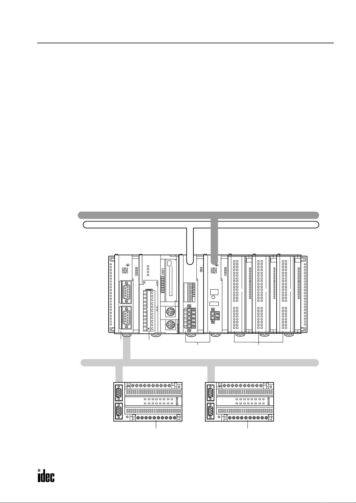
Open Network Communication System
The OpenNet Controller can be connected to three open network communication lines — DeviceNet, LONWORKS, and
INTERBUS.
OpenNet interface modules are available for communication through DeviceNet and LONWORKS networks. The OpenNet
interface modules, such as DeviceNet slav e modules and LONWORKS interface modules, serv e as a sla ve station or node in
the network.
A remote I/O system can be set up using a remote I/O master module mounted next to the CPU module and SX5S communication I/O terminals at remote I/O slave stations. When using 32 SX5S modules with 16 input or output points, a total of
512 I/O points can be distributed to 32 remote s lave stations at the maximum. The remote I/O network uses the INTERBUS protocol for communication. The total cable length can be 12.8 km (7.95 miles) maximum.
One remote I/O master module can be mounted with the
seven functional modules including OpenNet interface modules and analog I/O modules can be mounted with one Open-
Net Controller
.
OpenNet Controller CPU module. In addition, a maximum of
CPU module.
LONWORKS
DeviceNet
INTERBUS
Remote I/O
Master Module
V.24 InterfaceREMOTE OUT
RDY/
POWER
RUN
RUN
FAIL
BSA
ERROR
PF
HF
HSC OUT
COM A B Z
HSC
OUT
ABG
RS485
+24V 0V
idec
POW
MNS
I O
NO
H/L
DR1
DR0
NA5
NA4
NA3
NA2
NA1
NA0
idec
SERVICE
REQUEST
LON
POW
RUN
ERR
I/O
SER
idec
0
1
2
3
4
5
6
7
10
11
12
13
14
15
16
17
0
1
2
3
4
5
6
7
10
11
12
13
14
15
16
17
0
1
2
3
4
5
6
7
10
11
12
13
14
15
16
17
CPU
Module
OpenNet Interface Modules I/O Modules
UL
RC
BA
ER
RD
REMOTE OUT REMOTE IN
REMOTE OUT REMOTE IN
SX5S
INTERBUS
Remote I/O
REMOTE OUT REMOTE IN
REMOTE OUT REMOTE IN
SX5S
INTERBUS
Remote I/O
SX5S Communication I/O Terminals
OPENNET CONTROLLER USER’S MANUAL 1-3
UL
RC
BA
ER
RD
Page 13
1: GENERAL INFORMATION
Phone: 800.894.0412 - Fax: 888.723.4773 - Web: www.clrwtr.com - Email: info@clrwtr.com
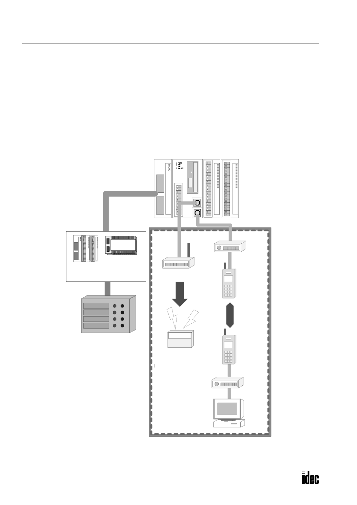
User Communication System
The OpenNet Controller CPU module has two RS232C ports and one RS485 port to control two RS232C devices and one
RS485 device such as IDEC’s HG series operator interface at the same time.
The figure below illustrates a system setup of remote I/O and user communication. In this example, the I/O statuses of a
remote machine are transferred through the remote I/O line to the CPU. The data received through modems is monitored
on a computer and also sent to a pager transmitter.
For details about the remote I/O system, see page 24-1.
For details about the modem mode, see page 23-1.
OpenNet Controller Master Station
Module Type
Slave Station
Remote Machine
Modem
Terminal Block Type
Pager Transmitter
Data
Transmission
Data
Communication
Pager
Modem
Computer
1-4 OPENNET CONTROLLER USER’S MANUAL
Page 14
1: GENERAL INFORMATION
Phone: 800.894.0412 - Fax: 888.723.4773 - Web: www.clrwtr.com - Email: info@clrwtr.com
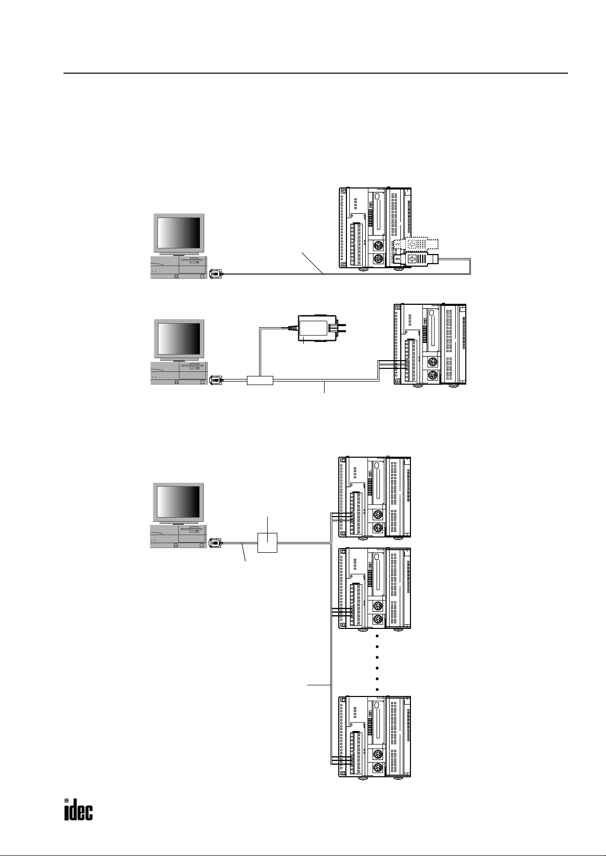
Computer Link System
When the OpenNet Controller is connected to a computer, operating status and I/O status can be monitored on the computer, data in the CPU module can be monitored or updated, and user programs can be downloaded and uploaded. A maximum of 32 OpenNet Controller CPU modules can be connected to one computer in the 1:N computer link system.
For details about the computer link communication, see page 22-1.
Computer Link 1:1 Communication
0
1
2
3
4
5
6
7
8
9
10
11
12
13
14
15
16
RS232C Port 1 or Port 2
17
Computer Link Cable 4C
FC2A-KC4C
3m (9.84 ft.) long
D-sub 9-pin Female Connector
0
1
2
3
4
5
6
7
8
9
10
11
12
13
14
15
16
AC Adapter
RS485
17
D-sub 9-pin
Female Connector
Computer Link 1:N Communication
RS232C/RS485 Converter
D-sub 9-pin
Female Connector
Twist-pair Shielded Cable
FC2A-MD1
RS232C Cable
HD9Z-C52
1.5m (4.92 ft.) long
Computer Link Cable 6C
FC2A-KC6C
2m (6.56 ft.) long
0
1
2
3
4
5
6
7
8
9
10
11
12
13
14
15
16
17
0
1
2
3
4
5
6
7
8
9
10
11
12
13
14
15
16
17
1st Unit
2nd Unit
0
1
2
3
4
5
6
7
8
9
10
11
12
13
14
15
32nd Unit
16
17
RS485
OPENNET CONTROLLER USER’S MANUAL 1-5
Page 15
1: GENERAL INFORMATION
Phone: 800.894.0412 - Fax: 888.723.4773 - Web: www.clrwtr.com - Email: info@clrwtr.com
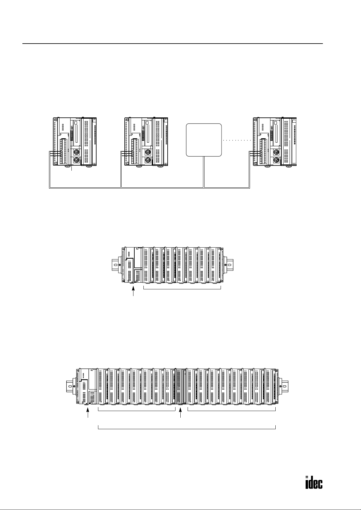
Data Link System
One OpenNet Controller at the master station can communicate with 31 slave stations through the RS485 line to exchange
data and perform distributed control effecti vely. The RS485 terminals are connected with each other using a 2-core twisted
pair cable.
For details about the data link communication, see page 21-1.
Master Station Slave Station 1 Slave Station 2
0
1
2
3
4
5
6
7
8
9
10
11
12
13
14
15
16
17
0
1
2
3
4
5
6
7
8
9
10
11
12
13
14
15
16
17
HG Series
Operator
Interface
Slave Station 31
0
1
2
3
4
5
6
7
8
9
10
11
12
13
14
15
16
17
Communication
Selector
DIP Switch
Basic System
The OpenNet Controller CPU module can be mounted with seven modules including digital I/O and functional modules
such as analog I/O, DeviceNet slave, and LONWORKS interf ace modules to set up a stand alone system. When using seven
digital I/O modules, the I/O points can be 224 points at the maximum.
7 modules (I/O and functional)
CPU Module
Expansion System
The FC3A-EA1 expansion power supply module is used to mount more than seven I/O and functional modules. When a
maximum of 15 I/O modules are mounted, the number of I/O points is expanded from 224 to 480 maximum.
Whether an expansion power supply module is used or not, sev en functional modules such as analog I/O, De viceNet sla ve,
ONWORKS interface modules can be mounted at the maximum in either the normal or expansion slots.
and L
CPU Module
7 modules (I/O and functional)
Expansion Power Supply Module
A maximum of 7 functional modules can be mounted in any of 15 slots
8 modules (I/O and functional)
1-6 OPENNET CONTROLLER USER’S MANUAL
Page 16
2: MODULE SPECIFICATIONS
Phone: 800.894.0412 - Fax: 888.723.4773 - Web: www.clrwtr.com - Email: info@clrwtr.com
Introduction
This chapter describes OpenNet Controller modules, parts names and specifications of each module.
Available modules include CPU modules, digital I/O modules, analog I/O modules, expansion power supply module,
remote I/O master module, and OpenNet interface modules such as DeviceNet slave and LONWORKS interface modules.
Analog I/O modules and OpenNet interface modules are also called functional modules. A maximum of seven functional
modules can be mounted with one CPU module.
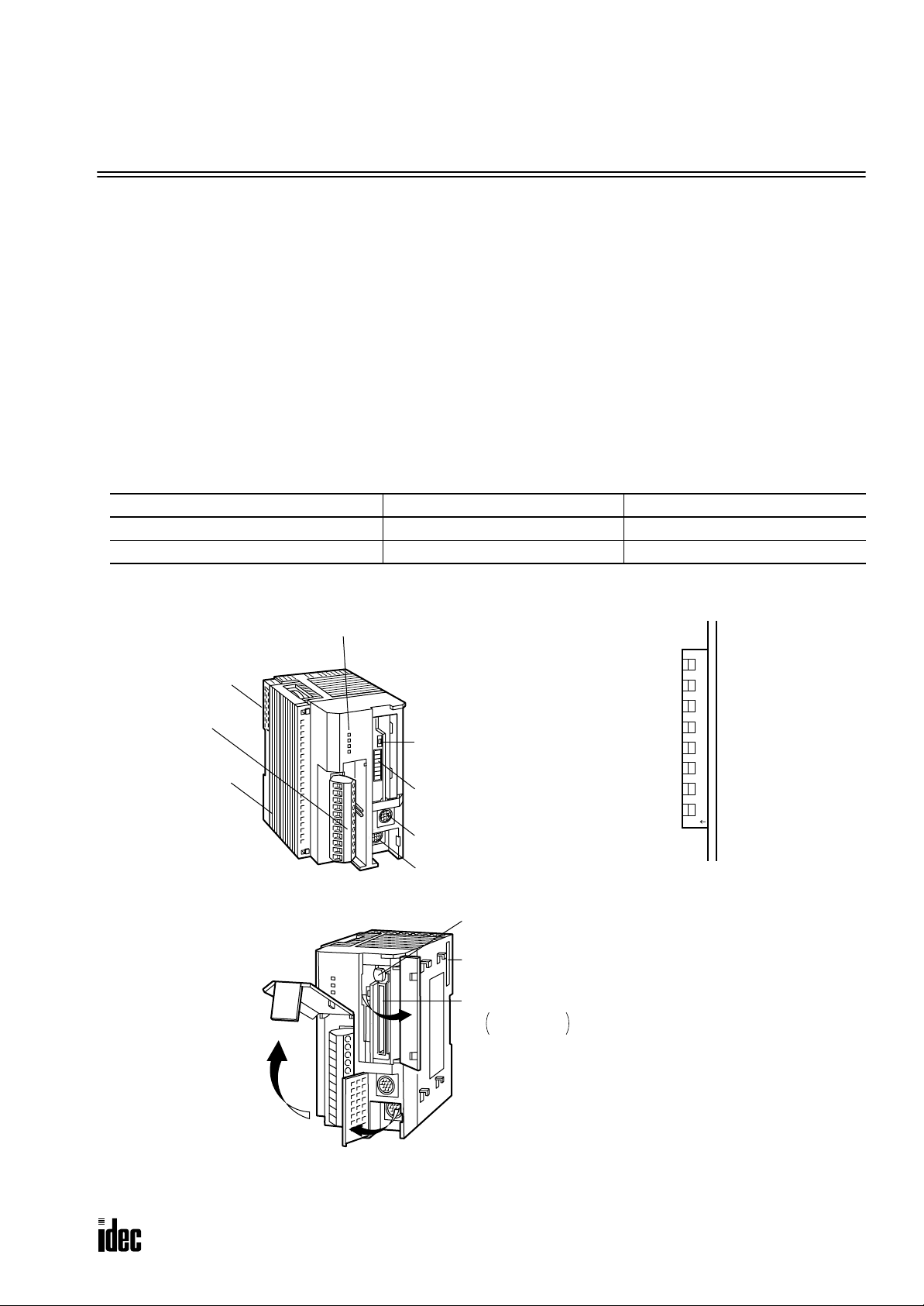
CPU Module
The CPU modules are available in sink and source output types which have a transistor sink or source output of the highspeed counter, respectively. Either type is available with or without a memory card connector. All CPU modules have two
RS232C ports and one RS485 port.
CPU Module Type Numbers
CPU Module Types Without Memory Card Connector With Memory Card Connector
High-speed Counter Sink Output Type FC3A-CP2K FC3A-CP2KM
High-speed Counter Source Output Type FC3A-CP2S FC3A-CP2SM
Parts Description
(10) Remote I/O
Master Module
Connector
(8) Terminal Block
(11) End Plate
(1) Status LED
(2) Communication
Enable Button
(3) Communication
Selector
DIP Switch
(7) RS232C Port 2
(6) RS232C Port 1
(5) Memory Card
Eject Button
(9) Expansion Connector
(4) Memory Card Connector
FC3A-CP2KM
FC3A-CP2SM
12345678
O
N
Communication Selector DIP Switch
Opening the Covers
Functions of each part are described on the following pages.
OPENNET CONTROLLER USER’S MANUAL 2-1
Page 17

2: MODULE SPECIFICATIONS
Phone: 800.894.0412 - Fax: 888.723.4773 - Web: www.clrwtr.com - Email: info@clrwtr.com
(1) Status LED
POWER Turns on when power is supplied to the CPU
RUN Turns on when the CPU is running
ERROR Turns on or flashes when an error occurs
HSC OUT Turns on when the high-speed counter comparison output is on
(2) Communication Enable Button
Enables the communication mode selected with the communication selector DIP switch. When the communication selector DIP switch setting is changed while the CPU is powered up, press this button to enable the new communication mode
for the RS485 and RS232C ports.
(3) Communication Selector DIP Switch
Selects the communication mode for the RS485 and RS232C ports, and also selects the device number for the CPU in the
computer link or data link communication network.
DIP Switch No. Function Setting
1 RS485 port communication mode ON: Data link mode OFF: Maintenance mode
2 RS232C port 1 communication mode ON: User communication mode OFF: Maintenance mode
3 RS232C port 2 communication mode ON: User communication mode OFF: Maintenance mode
4 to 8 Device number selection
Device numbers 0 through 31 for the CPU in the computer
link or data link communication network
Data link mode: Used for data link communication
User communication mode: Used for user communication or modem communication
Maintenance mode: Used for computer link communication between the CPU and WindLDR on computer
After changing the settings of the communication selector DIP switch while the CPU is powered up, press the communication enable button for more than 4 seconds until the ERROR LED blinks once; then the new communication mode for the
RS485 or RS232C port takes effect. When the CPU is powered up, the CPU checks the settings of the communication
selector DIP switch and enables the selected communication mode and device number automatically . You have to press the
communication enable button only when you change the DIP switch settings while the CPU is powered up.
Do not power up the CPU while the communication enable button is depressed and do not press the button unless it is necessary.
(4) Memory Card Connector
Plug a miniature memory card into the memory card connector. When a memory card is inserted, the CPU runs the user
program contained in the memory card instead of the user program stored in the CPU memory.
The memory card connector is provided on CPU modules FC3A-CP2KM and FC3A-CP2SM.
(5) Memory Card Eject Button
Press this button to eject the memory card from the CPU module.
(6) RS232C Port 1
Communication port used for the maintenance and user communication modes. User communication instructions TXD1
and RXD1 send and receive data through this port.
(7) RS232C Port 2
Communication port used for the maintenance and user communication modes. User communication instructions TXD2
and RXD2 send and receive data through this port.
2-2 OPENNET CONTROLLER USER’S MANUAL
Page 18

2: MODULE SPECIFICATIONS
Phone: 800.894.0412 - Fax: 888.723.4773 - Web: www.clrwtr.com - Email: info@clrwtr.com
(8) Terminal Block
Function Terminal No. Symbol Assignment
1 COM High-speed counter COM
High-speed Counter
Terminals
RS485 Port
Power Supply Terminals
(9) Expansion Connector
For connecting a digital I/O module or functional module.
(10) Remote I/O Master Module Connector
For connecting a remote I/O master module compatible with INTERBUS. This connector is located on the left side of the
CPU module and usually covered with an end plate. When connecting a remote I/O master module, remove the end plate
from the CPU module and attach the remote I/O master module.
2A High-speed counter phase A
3B High-speed counter phase B
4Z High-speed counter phase Z
5 HSC OUT High-speed counter comparison output
6 RS485 A RS485 line A
7 RS485 B RS485 line B
8 RS485 G RS485 line SG
9 +24V Power supply +24V DC
10 0V Power supply 0V DC
11 Frame ground
(11) End Plate
A pair of end plates are supplied with the CPU module. Remove the end plate from the CPU module before connecting
digital I/O and functional modules, then attach the end plates on both sides of the assembly. For removing the end plates,
see page 3-3.
OPENNET CONTROLLER USER’S MANUAL 2-3
Page 19

2: MODULE SPECIFICATIONS
Phone: 800.894.0412 - Fax: 888.723.4773 - Web: www.clrwtr.com - Email: info@clrwtr.com
General Specifications
Normal Operating Conditions
Operating Temperature 0 to 55°C (operating ambient temperature)
Storage Temperature –25 to +70°C
Relative Humidity Level RH1, 30 to 95% (non-condensing)
Pollution Degree 2 (IEC 60664-1)
Corrosion Immunity Free from corrosive gases
Altitude
Vibration Resistance
Shock Resistance
Weight (approx.)
Power Supply
Rated Power Voltage 24V DC
Allowable Voltage Range 19 to 30V DC (including ripple)
Dielectric Strength
Maximum Input Current 1.5A at 24V DC
Power Consumption
Allowable Momentary Power
Interruption
Insulation Resistance
Inrush Current 40A maximum (24V DC)
Ground Grounding resistance: 100Ω maximum
Grounding Wire UL1015 AWG22, UL1007 AWG18
Power Supply Wire UL1015 AWG22, UL1007 AWG18
Effect of Improper Power
Supply Connection
Operation: 0 to 2,000m (0 to 6,565 feet)
Transport: 0 to 3,000m (0 to 9,840 feet)
10 to 57 Hz amplitude 0.075 mm, 57 to 150 Hz acceleration 9.8 m/sec
10 sweep cycles per axis on each of three mutually perpendicular axes
(total 80 minutes each) (IEC1131)
147 m/sec
dicular axes (IEC1131)
FC3A-CP2K/CP2S (w/o memory card connector): 290g
FC3A-CP2KM/CP2SM (w/memory card connector): 300g
Between power terminal and FG: 500V AC, 1 minute
Between I/O terminal and FG: 1,500V AC, 1 minute
8.4W (24V): CPU module + 48 I/Os (32-DC input module + 16-relay output module)
18W (24V): CPU module + 128 I/Os (32-DC input module × 2 + 16-DC input mod-
11.8W (24V): CPU module + remote I/O master module + 48 I/Os (32-DC input mod-
21.4W (24V): CPU module + remote I/O master module + 128 I/Os (32-DC input
10 msec (24V DC), Level PS-2 (EN61131)
Between power terminal and FG: 10 MΩ minimum (500V DC megger)
Between I/O terminal and FG: 10 MΩ minimum (500V DC megger)
Reverse polarity: No operation, no damage
Improper voltage or frequency: Permanent damage may be caused
Improper lead connection: Permanent damage may be caused
2
(15G), 11 msec duration, 3 shocks per axis, on three mutually perpen-
ule + 16-relay output module × 3)
ule + 16-relay output module)
module × 2 + 16-DC input module + 16-relay output module × 3)
2
(1G)
2-4 OPENNET CONTROLLER USER’S MANUAL
Page 20

2: MODULE SPECIFICATIONS
Phone: 800.894.0412 - Fax: 888.723.4773 - Web: www.clrwtr.com - Email: info@clrwtr.com
Function Specifications
CPU Module Specifications
Program Capacity 16K words (8K steps)
Quantity of Slots
I/O
User Program Memory Flash ROM, RAM, memory card
RAM
Backup
Control System Stored program system (not in compliance with EN61131-3)
Instruction Words
Processing Time
Internal Relay 2,048 points
Data Register 8,000 points
Counter 256 points (adding, dual pulse reversible, up/down selection reversible)
Timer 256 points (1-sec, 100-msec, 10-msec, 1-msec)
Catch Input
Calendar/Clock
Self-diagnostic Function
Start/Stop Method
Maximum Digital
I/O Points
Backup Duration Approx. 30 days (typical) at 25°C after backup battery fully charged
Backup Data Internal relay, shift register, counter, data register
Battery Lithium secondary battery
Charging Speed Approx. 2 hours from 0% to 90% of full charge
Battery Life Approx. 10 years using in cycles of 9-hour charging, 15-hour discharging
Replaceability Impossible
7 slots maximum (without using expansion power supply module)
15 slots maximum (when using expansion power supply module)
224 points (without using expansion power supply module)
480 points (when using expansion power supply module)
• 56 points when using 7 modules of 8-point I/O
• 112 points when using 7 modules of 16-point I/O
• 224 points when using 7 modules of 32-point I/O
• 480 points when using 15 modules of 32-point I/O
37 basic instructions
65 advanced instructions
Basic/advanced instruction: See page A-1.
END processing: See page A-2.
Clock/calendar processing: One cycle in 100 msec (see page A-2)
Data link master station processing: See pages page 21-1 and page 21-10.
First 8 channels of each input module can be designated as catch inputs
Minimum turn on pulse width: 40 µsec maximum
Minimum turn off pulse width: 150 µsec maximum
Accuracy: ±30 sec/month at 25°C (typical)
Backup duration: Approx. 30 days 25°C (typical)
Keep data sum check, WDT check, user program RAM sum check, user program ROM
sum check, user program write check, power failure check, timer/counter preset
value sum check, calendar/clock error check, user program syntax check, data link
connection check, I/O bus check, I/O bus initialization check, user program execution
check
Turning power on and off
Start/stop command in WindLDR
Turning start control special internal relay M8000 on and off
Turning designated stop or reset input off and on
OPENNET CONTROLLER USER’S MANUAL 2-5
Page 21

2: MODULE SPECIFICATIONS
Phone: 800.894.0412 - Fax: 888.723.4773 - Web: www.clrwtr.com - Email: info@clrwtr.com
System Statuses at Stop, Reset, and Restart
Internal Relays, Shift Registers,
Mode Outputs
Run Operating Operating Operating Operating Operating
Reset (Reset input ON) OFF OFF/Reset to zero OFF/Reset to zero Reset to zero Reset to zero
Stop (Stop input ON) OFF Unchanged Unchanged Unchanged Unchanged
Restart Unchanged Unchanged OFF/Reset to zero Reset to preset Unchanged
Note: Link registers used as outputs are turned off like outputs.
Counters, Data Registers
Keep Type Clear Type
Communication Function
Communication Port RS232C Port 1 RS232C Port 2 RS485 Port
Standards EIA RS232C EIA RS232C EIA RS485
Baud Rate 19,200 bps 19,200 bps
Maintenance Communication Possible Possible Possible
User Communication Possible Possible Impossible
Data Link Communication Impossible Impossible Possible
Quantity of Slave Stations ——31
Maximum Cable Length Special cable Special cable 200m *
Isolation between Power Supply and
Communication Port
Not isolated Not isolated Not isolated
Timer
Current Value
Computer link: 19,200 bps
Data link: 38,400 bps
Link Register
(Note)
* Recommended cable for data link: Twisted-pair shielded cable with a minimum core wire diameter of 0.9 mm.
Conductor resistance 85 Ω/km maximum, shield resistance 20 Ω/km maximum.
Communication Selector DIP Switch Settings
DIP Switch No. Function Setting
1 RS485 port communication mode ON: Data link mode OFF: Maintenance mode
2 RS232C port 1 communication mode ON: User communication mode OFF: Maintenance mode
3 RS232C port 2 communication mode ON: User communication mode OFF: Maintenance mode
4 to 8 Device number selection Device numbers 0 through 31 for the CPU
Memory Card
Card Type Miniature memory card
Accessible Memory Capacity 2MB, 5V type
Download Destination CPU module (FC3A-CP2KM and -CP2SM)
Software for Writing Card WindLDR
Quantity of Stored Programs One user program stored on one memory card
Program Execution Priority When a memory card is inserted, user program on the memory card is executed.
High-speed Counter
Maximum Counting Frequency 10 kHz
Counting Range 0 to 65535 (16 bits)
Operation Mode
Comparison Output
Rotary encoder mode
Dual-pulse reversible counter mode
Transistor sink or source output 1 point (500mA)
Output delay: 20 µsec
2-6 OPENNET CONTROLLER USER’S MANUAL
Page 22
2: MODULE SPECIFICATIONS
Phone: 800.894.0412 - Fax: 888.723.4773 - Web: www.clrwtr.com - Email: info@clrwtr.com
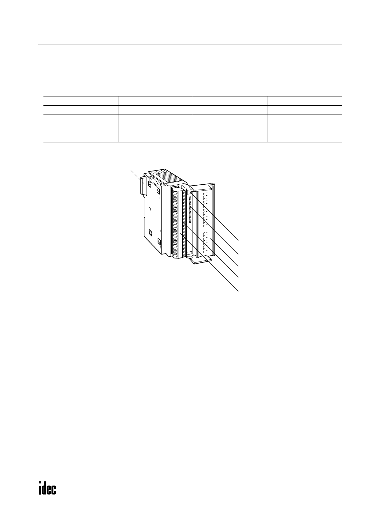
Input Module
Digital input modules are available in 16- and 32-point DC input modules and 8-point AC input modules. Four different
connector/terminal styles are available.
Input Module Type Numbers
Module Name 16-point DC Input 32-point DC Input 8-point AC Input
Screw Terminal FC3A-N16B1 — FC3A-N08A11
Nylon Connector
Fujitsu Connector — FC3A-N32B5 —
Parts Description
(6) Expansion Connector
FC3A-N16B3 ——
— FC3A-N32B4 —
(1) Module ID
(2) Status LED
(3) Terminal Block Cover
(4) Cable Terminal/Connector
This figure illustrates a screw terminal type input module.
(5) Terminal Label
(1) Module ID Indicates the input module ID.
DC IN: 24V DC sink/source input, 16 or 32 points
AC IN: 100V AC input, 8 points
(2) Status LED Turns on when input is on.
(3) Terminal Block Cover The terminal block cover flips open to the right.
When using long ferrules for wiring, the terminal block cover may be removed.
(4) Cable Terminal/Connector Five different terminal/connector styles are available for wiring.
(5) Terminal Label Indicates terminal numbers 1 through 20 on the terminal block.
(6) Expansion Connector Connects to CPU and other modules.
OPENNET CONTROLLER USER’S MANUAL 2-7
Page 23

2: MODULE SPECIFICATIONS
Phone: 800.894.0412 - Fax: 888.723.4773 - Web: www.clrwtr.com - Email: info@clrwtr.com
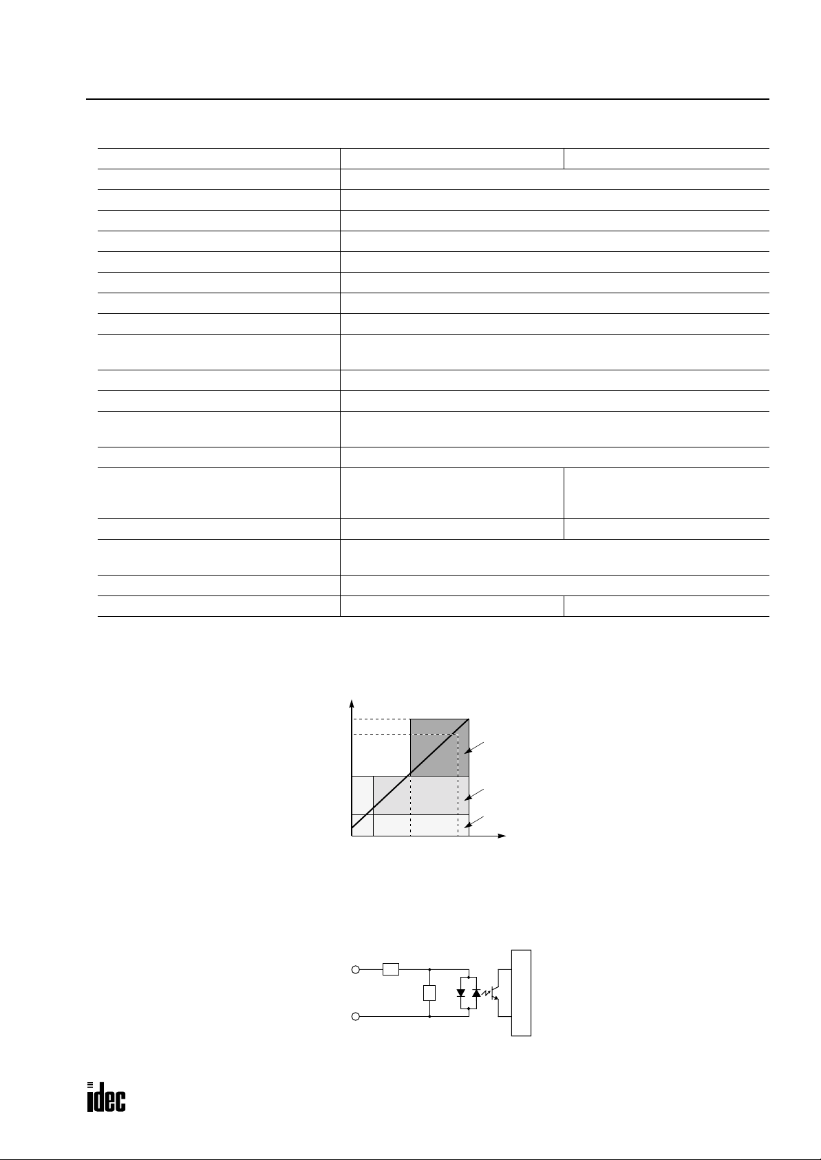
16-point DC Input Module Specifications
Type No. FC3A-N16B1 FC3A-N16B3
Rated Input Voltage 24V DC sink/source input signal
Input Voltage Range 19 to 30V DC
Rated Input Current 7 mA/point (24V DC)
Terminal Arrangement See Terminal Arrangement charts on pages 2-11 and 2-12.
Input Impedance 3.4 kΩ
Turn ON Time (24V DC) 20 µsec + filter preset
Turn OFF Time (24V DC) 120 µsec + filter preset
Input Filter 0 msec, 0.5 msec, 1 msec, 2 msec, 4 msec, 8 msec, 16 msec, 32 msec
Isolation
External Load for I/O Interconnection Not needed
Signal Determination Method Static
Effect of Improper Input Connection
Cable Length 3m (9.84 ft.) in compliance with electromagnetic immunity
Connector on Mother Board
Connector Insertion/Removal Durability 100 times minimum 50 times minimum
Internal Current Draw
Weight (approx.) 210g 180g
Between input terminals: Not isolated
Internal circuit: Photocoupler isolated
Both sinking and sourcing input signals can be connected. If any input
exceeding the rated value is applied, permanent damage may be caused.
Screw Terminal Block
MSTBA2.5/20-G5.08
(Phoenix Contact)
Nylon Connector
B10PS-VH × 2
(J.S.T. Mfg.)
All inputs ON: 40 mA (24V DC)
All inputs OFF: 10 mA (24V DC)
Input Operating Range
The input operating range of the Type 1 (EN61131) input module is shown below:
30
24
15
Input Voltage (V DC)
5
0
1.5 8.8
Input Current (mA)
74.4
ON Area
Transition
Area
OFF Area
Input Internal Circuit
COM
Input
3.3 kΩ
Internal Circuit
2-8 OPENNET CONTROLLER USER’S MANUAL
Page 24
2: MODULE SPECIFICATIONS
Phone: 800.894.0412 - Fax: 888.723.4773 - Web: www.clrwtr.com - Email: info@clrwtr.com
32-point DC Input Module Specifications
Type No. FC3A-N32B4 FC3A-N32B5
Rated Input Voltage 24V DC sink/source input signal
Input Voltage Range 20.4 to 27.6V DC
Rated Input Current 4.9 mA/point (24V DC)
Terminal Arrangement See Terminal Arrangement charts on pages 2-13 and 2-14.
Input Impedance 4.7 kΩ
Turn ON Time (24V DC) 20 µsec + filter preset
Turn OFF Time (24V DC) 120 µsec + filter preset
Input Filter 0 msec, 0.5 msec, 1 msec, 2 msec, 4 msec, 8 msec, 16 msec, 32 msec
Isolation
External Load for I/O Interconnection Not needed
Signal Determination Method Static
Effect of Improper Input Connection
Cable Length 3m (9.84 ft.) in compliance with electromagnetic immunity
Connector on Mother Board
Connector Insertion/Removal Durability 50 times minimum 500 times minimum
Internal Current Draw
Allowable Simultaneous ON Inputs 70% maximum
Weight (approx.) 230g 240g
Between input terminals: Not isolated
Internal circuit: Photocoupler isolated
Both sinking and sourcing input signals can be connected. If any input
exceeding the rated value is applied, permanent damage may be caused.
Nylon Connector
BS18P-SHF-1AA × 2
(J.S.T. Mfg.)
Fujitsu Connector
FCN-365P040-AU
(Fujitsu)
All inputs ON: 50 mA (24V DC)
All inputs OFF: 10 mA (24V DC)
Input Operating Range
The input operating range of the Type 1 (EN61131) input module is shown below:
27.6
24
15
5
Input Voltage (V DC)
0
1 5.4
Input Current (mA)
4.4
4.9
ON Area
Transition
Area
OFF Area
Input Internal Circuit
COM
Input
4.7 kΩ
Internal Circuit
OPENNET CONTROLLER USER’S MANUAL 2-9
Page 25

2: MODULE SPECIFICATIONS
Phone: 800.894.0412 - Fax: 888.723.4773 - Web: www.clrwtr.com - Email: info@clrwtr.com
8-point AC Input Module Specifications
Type No. FC3A-N08A11
Rated Input Voltage 100 to 120V AC
Input Voltage Range 85 to 132V AC
Rated Input Current 8.3 mA/point (100V AC, 60 Hz)
Terminal Arrangement See Terminal Arrangement chart on page 2-15.
Input Impedance 12 kΩ (60 Hz)
Turn ON Time (100V AC) 20 msec maximum
Turn OFF Time (100V AC) 20 msec maximum
Isolation
External Load for I/O Interconnection Not needed
Signal Determination Method Static
Effect of Improper Input Connection
Cable Length 3m (9.84 ft.) in compliance with electromagnetic immunity
Connector on Mother Board
Connector Insertion/Removal Durability 100 times minimum
Internal Current Draw
Weight (approx.) 220g
Between input terminals: Not isolated
Internal circuit: Photocoupler isolated
If any input exceeding the rated value is applied, permanent damage may
be caused.
Screw Terminal Block
MSTBA2.5/20-G5.08
(Phoenix Contact)
All inputs ON: 30 mA (24V DC)
All inputs OFF: 20 mA (24V DC)
Input Operating Range
The input operating range of the Type 1 (EN61131) input module is shown below:
132
100
79
Input Voltage (V AC)
20
0
1.6 11
Input Current (mA)
8.36.5
ON Area
Transition
Area
OFF Area
Input Internal Circuit
COM
Input
Internal Circuit
2-10 OPENNET CONTROLLER USER’S MANUAL
Page 26

Input Module Terminal Arrangement
Phone: 800.894.0412 - Fax: 888.723.4773 - Web: www.clrwtr.com - Email: info@clrwtr.com
FC3A-N16B1 (16-point DC Input Module) — Screw Terminal Type
Applicable Connector: SMSTB2.5/20-ST-5.08 (Phoenix Contact)
DC
IN
0
1
2
3
4
5
6
7
10
11
12
13
14
15
16
17
2: MODULE SPECIFICATIONS
Terminal No. Name
1 COM
2 COM
3I0
4I1
5I2
6I3
7I4
8I5
9I6
10 I7
11 COM
12 COM
13 I10
14 I11
15 I12
16 I13
17 I14
18 I15
19 I16
20 I17
Wiring Schematic
• COM terminals are connected together internally.
• Terminal numbers are marked on the terminal block label on the input module.
• For wiring precautions, see page 3-5.
Sink Input Wiring
+ –
Terminal No. Name
1 COM
2 COM
3I0
4I1
5I2
6I3
7I4
8I5
9I6
10 I7
11 COM
12 COM
13 I10
14 I11
15 I12
16 I13
17 I14
18 I15
19 I16
20 I17
Source Input Wiring
+–
Terminal No. Name
1 COM
2 COM
3I0
4I1
5I2
6I3
7I4
8I5
9I6
10 I7
11 COM
12 COM
13 I10
14 I11
15 I12
16 I13
17 I14
18 I15
19 I16
20 I17
OPENNET CONTROLLER USER’S MANUAL 2-11
Page 27
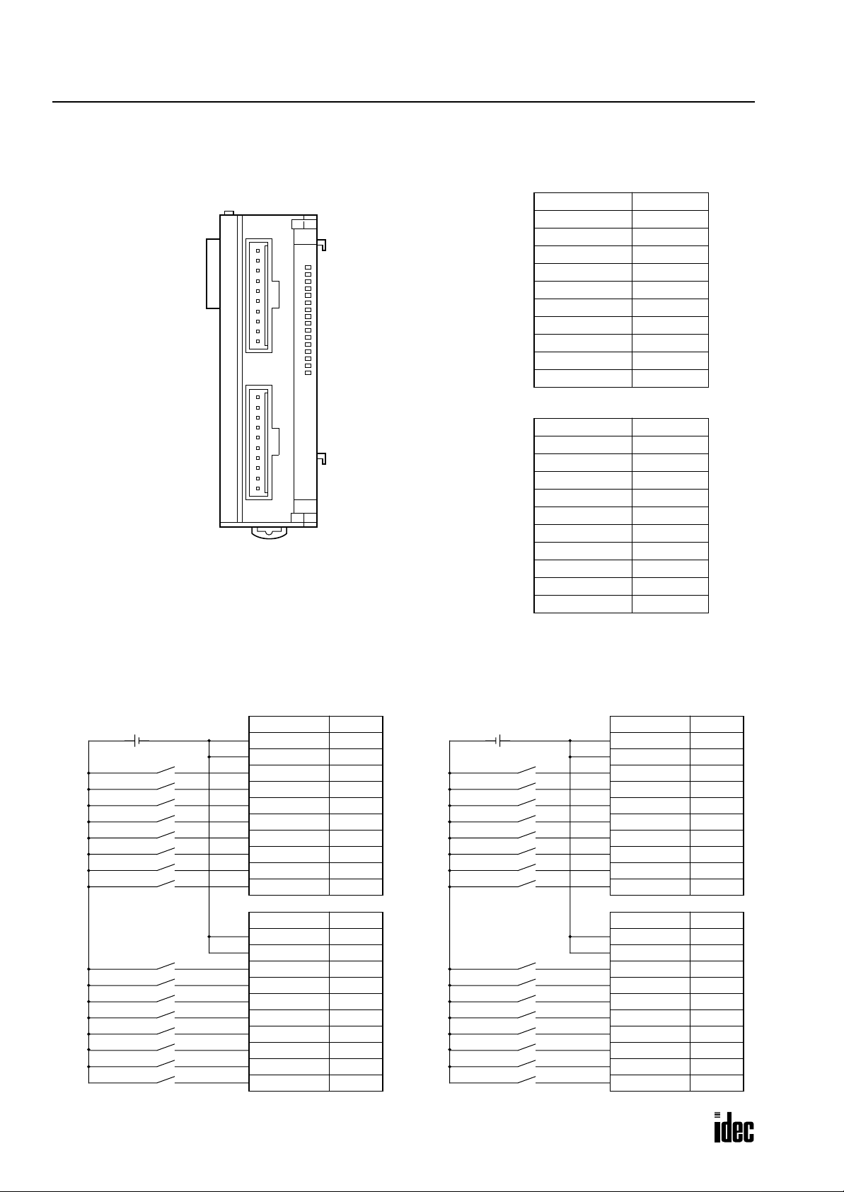
2: MODULE SPECIFICATIONS
CN1
Phone: 800.894.0412 - Fax: 888.723.4773 - Web: www.clrwtr.com - Email: info@clrwtr.com
FC3A-N16B3 (16-point DC Input Module) — Nylon Connector Type
Applicable Connectors: VHR-10N (J.S.T. Mfg.)
SVH-21T-P1.1 (J.S.T. Mfg.)
CN1
CN2
Wiring Schematic
• COM terminals are connected together internally.
• Terminal numbers are marked on the female connector on the cable.
• For wiring precautions, see page 3-5.
DC
IN
0
1
2
3
4
5
6
7
10
11
12
13
14
15
16
17
Terminal No. Name
1 COM
2 COM
3I0
4I1
5I2
6I3
7I4
8I5
9I6
10 I7
CN2
Terminal No. Name
1 COM
2 COM
3 I10
4 I11
5 I12
6 I13
7 I14
8 I15
9 I16
10 I17
Sink Input Wiring
+ –
CN1
Terminal No. Name
1 COM
2 COM
3I0
4I1
5I2
6I3
7I4
8I5
9I6
10 I7
CN2
Terminal No. Name
1 COM
2 COM
3 I10
4 I11
5 I12
6 I13
7 I14
8 I15
9 I16
10 I17
Source Input Wiring
+–
CN1
Terminal No. Name
1 COM
2 COM
3I0
4I1
5I2
6I3
7I4
8I5
9I6
10 I7
CN2
Terminal No. Name
1 COM
2 COM
3 I10
4 I11
5 I12
6 I13
7 I14
8 I15
9 I16
10 I17
2-12 OPENNET CONTROLLER USER’S MANUAL
Page 28
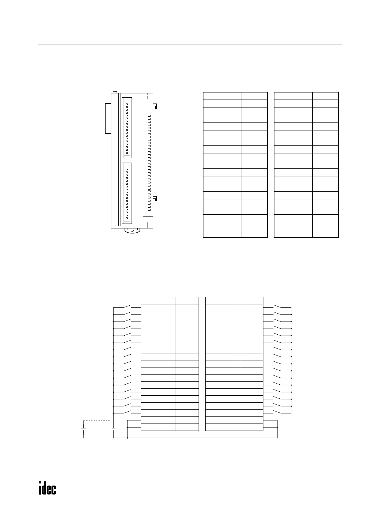
FC3A-N32B4 (32-point DC Input Module) — Nylon Connector Type
Phone: 800.894.0412 - Fax: 888.723.4773 - Web: www.clrwtr.com - Email: info@clrwtr.com
Applicable Connector: H18-SHF-AA (J.S.T. Mfg.)
SHF-001T-0.8BS (J.S.T. Mfg.)
2: MODULE SPECIFICATIONS
CN1
CN1
CN2
DC
IN
0
1
2
3
4
5
6
7
10
11
12
13
14
15
16
17
20
21
22
23
24
25
26
27
30
31
32
33
34
35
36
37
Terminal No. Name
Wiring Schematic
• COM terminals are connected together internally.
• Terminal numbers are marked on the female connector on the cable.
• For wiring precautions, see page 3-5.
18 I0
17 I1
16 I2
15 I3
14 I4
13 I5
12 I6
11 I7
10 I10
9 I11
8 I12
7 I13
6 I14
5 I15
4 I16
3 I17
2 COM
1 COM
CN2
Terminal No. Name
18 I20
17 I21
16 I22
15 I23
14 I24
13 I25
12 I26
11 I27
10 I30
9 I31
8 I32
7 I33
6 I34
5 I35
4 I36
3 I37
2 COM
1 COM
+
–
Sink
Input
Wiring
–
+
Source
Input
Wiring
CN1
Terminal No. Name
18 I0
17 I1
16 I2
15 I3
14 I4
13 I5
12 I6
11 I7
10 I10
9 I11
8 I12
7 I13
6 I14
5 I15
4 I16
3 I17
2 COM
1 COM
CN2
Terminal No. Name
18 I20
17 I21
16 I22
15 I23
14 I24
13 I25
12 I26
11 I27
10 I30
9 I31
8 I32
7 I33
6 I34
5 I35
4 I36
3 I37
2 COM
1 COM
OPENNET CONTROLLER USER’S MANUAL 2-13
Page 29
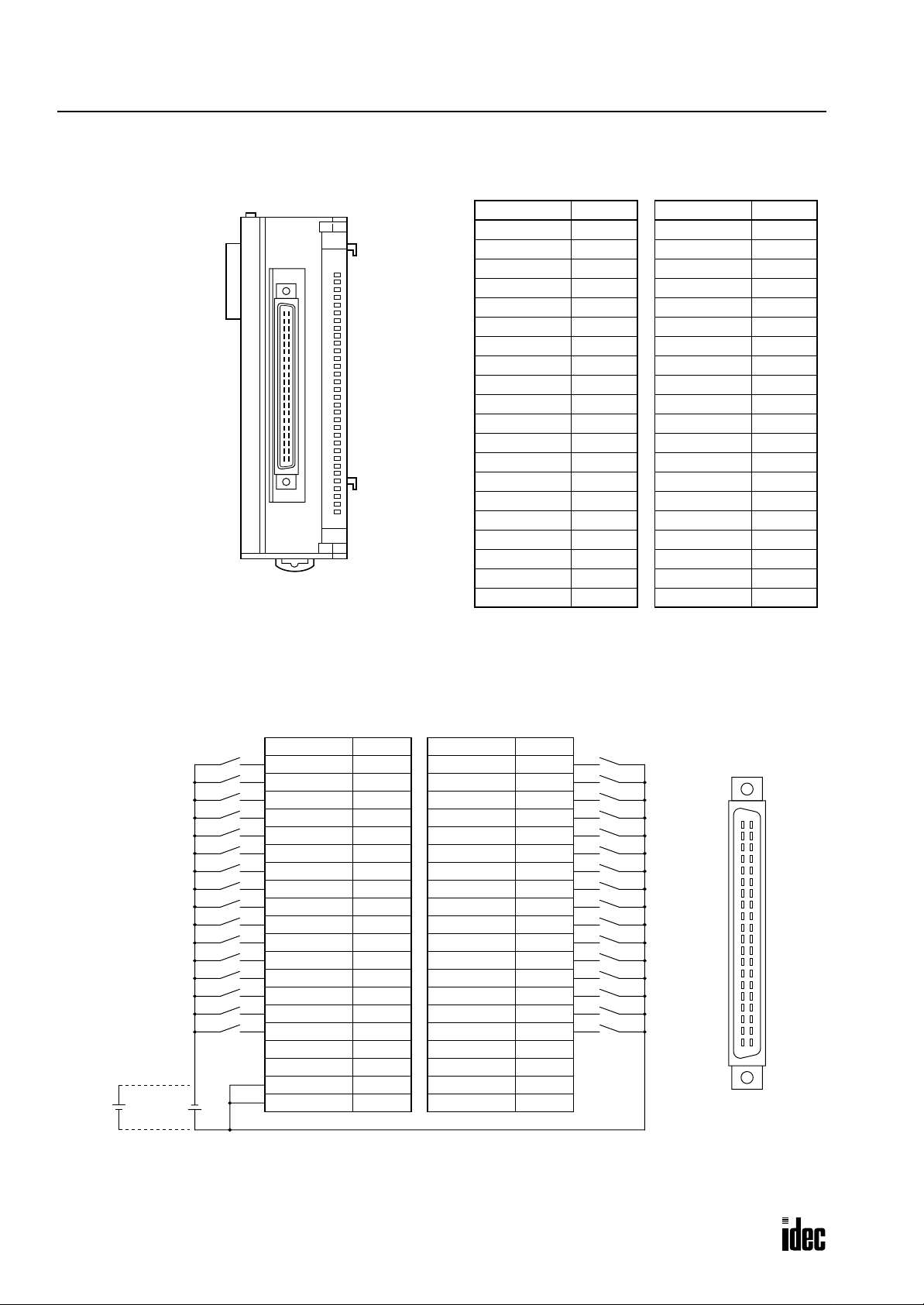
2: MODULE SPECIFICATIONS
Phone: 800.894.0412 - Fax: 888.723.4773 - Web: www.clrwtr.com - Email: info@clrwtr.com
FC3A-N32B5 (32-point DC Input Module) — Fujitsu Connector Type
Applicable Connector: FCN-367J040-AU (Fujitsu)
Terminal No. Name
DC
IN
0
1
2
3
4
5
6
7
10
11
12
13
14
15
16
17
20
21
22
23
24
25
26
27
30
31
32
33
34
35
36
37
B20 I0
B19 I1
B18 I2
B17 I3
B16 I4
B15 I5
B14 I6
B13 I7
B12 I10
B11 I11
B10 I12
B9 I13
B8 I14
B7 I15
B6 I16
B5 I17
B4 NC
B3 NC
B2 COM
B1 COM
Wiring Schematic
• COM terminals are connected together internally.
• Terminal numbers are the front view of the male connector on the input module.
• For wiring precautions, see page 3-5.
Terminal No. Name
A20 I20
A19 I21
A18 I22
A17 I23
A16 I24
A15 I25
A14 I26
A13 I27
A12 I30
A11 I31
A10 I32
A9 I33
A8 I34
A7 I35
A6 I36
A5 I37
A4 NC
A3 NC
A2 NC
A1 NC
Sink
Input
Wiring
Terminal No. Name
B20 I0
B19 I1
B18 I2
B17 I3
B16 I4
B15 I5
B14 I6
B13 I7
B12 I10
B11 I11
B10 I12
B9 I13
B8 I14
B7 I15
B6 I16
B5 I17
B4 NC
B3 NC
B2 COM
+
–
–
+
B1 COM
Terminal No. Name
A20 I20
A19 I21
A18 I22
A17 I23
A16 I24
A15 I25
A14 I26
A13 I27
A12 I30
A11 I31
A10 I32
A9 I33
A8 I34
A7 I35
A6 I36
A5 I37
A4 NC
A3 NC
A2 NC
A1 NC
B20
B19
B18
B17
B16
B15
B14
B13
B12
B11
B10
A20
A19
A18
A17
A16
A15
A14
A13
A12
A11
A10
B9
B8
B7
B6
B5
B4
B3
B2
B1
A9
A8
A7
A6
A5
A4
A3
A2
A1
Source
Input
Wiring
2-14 OPENNET CONTROLLER USER’S MANUAL
Page 30
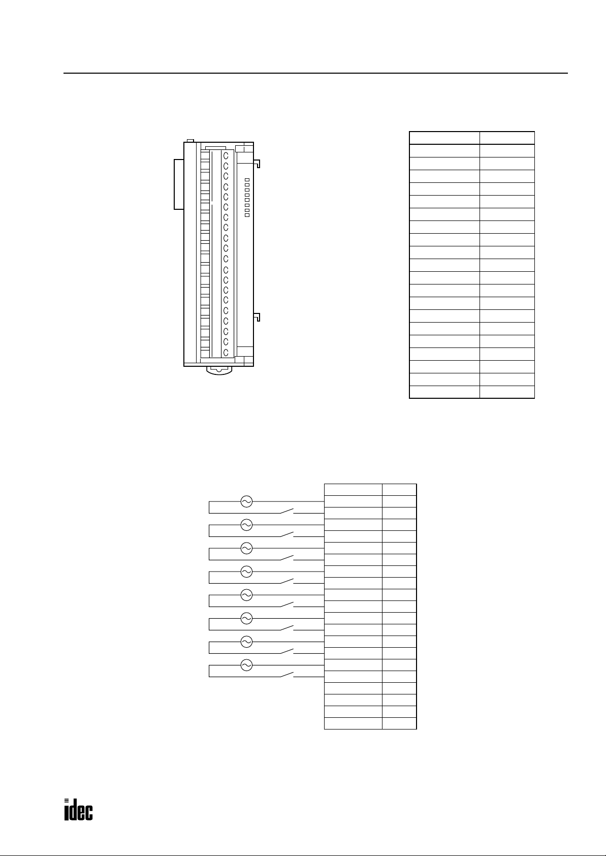
FC3A-N08A11 (8-point AC Input Module) — Screw Terminal Type
Phone: 800.894.0412 - Fax: 888.723.4773 - Web: www.clrwtr.com - Email: info@clrwtr.com
Applicable Connector: SMSTB2.5/20-ST-5.08 (Phoenix Contact)
AC
IN
0
1
2
3
4
5
6
7
2: MODULE SPECIFICATIONS
Terminal No. Name
1 COM0
2I0
3 COM1
4I1
5 COM2
6I2
7 COM3
8I3
9 COM4
10 I4
11 COM5
12 I5
13 COM6
14 I6
15 COM7
16 I7
17 NC
18 NC
19 NC
20 NC
Wiring Schematic
• COM terminals are not connected together internally.
• Terminal numbers are marked on the terminal block label on the input module.
• For wiring precautions, see page 3-5.
Terminal No. Name
1 COM0
2I0
3 COM1
4I1
5 COM2
6I2
7 COM3
8I3
9 COM4
10 I4
11 COM5
12 I5
13 COM6
14 I6
15 COM7
16 I7
17 NC
18 NC
19 NC
20 NC
OPENNET CONTROLLER USER’S MANUAL 2-15
Page 31

2: MODULE SPECIFICATIONS
Phone: 800.894.0412 - Fax: 888.723.4773 - Web: www.clrwtr.com - Email: info@clrwtr.com
Output Module
Digital output modules are available in 16-point relay output modules, 16- and 32-point transistor sink output modules,
and 16-point transistor protect source output modules. Five different connector/terminal styles are available.
Output Module Type Numbers
Module Name
Screw Terminal FC3A-R161 FC3A-T16K1 FC3A-T16P1 —
Nylon Connector
Fujitsu Connector —— —FC3A-T32K5
16-point
Relay Output
FC3A-R162 ———
— FC3A-T16K3 ——
—— —FC3A-T32K4
16-point Transistor
Sink Output
16-point Transistor
Protect Source Output
32-point Transistor
Sink Output
Parts Description
(6) Expansion Connector
(1) Module ID
(2) Status LED
(3) Terminal Block Cover
(4) Cable Terminal/Connector
This figure illustrates a screw terminal type output module.
(5) Terminal Label
(1) Module ID Indicates the output module ID.
Ry OUT: Relay output, 16 points
Tr OUT: Transistor output, 16 or 32 points
(2) Status LED Turns on when output is on.
(3) Terminal Block Cover The terminal block cover flips open to the right.
When using long ferrules for wiring, the terminal block cover may be removed.
(4) Cable Terminal/Connector Six different connector/terminal styles are available
(5) Terminal Label Indicates terminal numbers 1 through 20 on the terminal block.
(6) Expansion Connector Connects to CPU and other modules.
2-16 OPENNET CONTROLLER USER’S MANUAL
Page 32

2: MODULE SPECIFICATIONS
Inductive Load
COM
C
R
Output Q
Inductive Load
COM
R
Output Q
C
+or–
Inductive Load
COM
Output Q
+–
Inductive Load
COM
Output Q
+or–
Varistor
Protection circuit A can be used when the load impedance is
smaller than the RC impedance in an AC load power circuit.
C: 0.1 to 1 µF
R: Resistor of about the same resistance value as the load
Protection circuit B can be used for both AC and DC load
power circuits.
C: 0.1 to 1 µF
R: Resistor of about the same resistance value as the load
Protection circuit D can be used for both AC and DC load
power circuits.
Protection Circuit A Protection Circuit B
Protection Circuit C Protection Circuit D
Protection circuit C can be used for DC load power circuits.
Use a diode with the following ratings.
Reverse withstand voltage: Power voltage of the load circuit × 10
Forward current: More than the load current
Phone: 800.894.0412 - Fax: 888.723.4773 - Web: www.clrwtr.com - Email: info@clrwtr.com
16-point Relay Output Module Specifications
Type No. FC3A-R161 FC3A-R162
Terminal Arrangement See Terminal Arrangement charts on pages 2-22 and 2-23.
Output Points and Common Lines 16 NO contacts in 4 common lines (COM terminals not connected together)
Maximum Load Current
Minimum Switching Load 0.1 mA/0.1V DC (reference value)
Initial Contact Resistance 30 mΩ maximum
Electrical Life 100,000 operations minimum (rated load 1,800 operations/hour)
Mechanical Life 20,000,000 operations minimum (no load 18,000 operations/hour)
Rated Load Voltage (resistive/inductive) 240V AC/2A, 30V DC/2A
Dielectric Strength
Connector on Mother Board
Connector Insertion/Removal Durability 100 times minimum 50 times minimum
Internal Current Draw
Output Delay
Weight (approx.) 260g 230g
2A per point
8A per common line 7A per common line
Between output terminal and FG: 1,500V AC, 1 minute
Between output terminal and internal circuit: 1,500V AC, 1 minute
Between output terminals (COMs): 1,500V AC, 1 minute
Screw Terminal Block
MSTBA2.5/20-G5.08
(Phoenix Contact)
Nylon Connector
B5PS-VH × 4
(J.S.T. Mfg.)
All outputs ON: 170 mA (24V DC)
All outputs OFF: 20 mA (24V DC)
Turn ON time: 6 msec maximum
Chatter: 6 msec maximum
Turn OFF time: 10 msec maximum
Contact Protection Circuit for Relay Output
Depending on the load, a protection circuit may be needed for the relay output of the OpenNet Controller. Choose a protection circuit from A through D sho wn below according to the power supply and connect the protection circuit to the outside
of the relay output module.
OPENNET CONTROLLER USER’S MANUAL 2-17
Page 33

2: MODULE SPECIFICATIONS
Phone: 800.894.0412 - Fax: 888.723.4773 - Web: www.clrwtr.com - Email: info@clrwtr.com
16-point Transistor Sink Output Module Specifications
Type No. FC3A-T16K1 FC3A-T16K3
Terminal Arrangement See Terminal Arrangement charts on pages 2-24 and 2-25.
Rated Load Voltage 24V DC
Operating Load Voltage Range 19 to 30V DC
Rated Load Current 0.5A per output point
Maximum Load Current
Voltage Drop (ON Voltage) 1V maximum (voltage between COM and output terminals when output is on)
Inrush Current 5A maximum
Leakage Current 0.1 mA maximum
Clamping Voltage 39V±1V
Maximum Lamp Load 10W
Inductive Load L/R = 10 msec (30V DC, 0.5 Hz)
External Current Draw 100 mA maximum, 24V DC (power voltage at the +V terminal)
Isolation
Connector on Mother Board
Connector Insertion/Removal Durability 100 times minimum 50 times minimum
Internal Current Draw
Output Delay
Weight (approx.) 220g 190g
0.625A per output point (at 30V DC)
5A per common line (at 30V DC)
Between output terminal and internal circuit: Photocoupler isolated
Between output terminals: Not isolated
Screw Terminal Block
MSTBA2.5/20-G5.08
(Phoenix Contact)
All outputs ON: 60 mA (24V DC)
All outputs OFF: 20 mA (24V DC)
Turn ON time: 500 µsec maximum
Turn OFF time: 500 µsec maximum
Nylon Connector
B10PS-VH × 2
(J.S.T. Mfg.)
Output Internal Circuit
Internal Circuit
+V
Output
COM (–)
COM terminals are connected together internally.
2-18 OPENNET CONTROLLER USER’S MANUAL
Page 34

2: MODULE SPECIFICATIONS
Phone: 800.894.0412 - Fax: 888.723.4773 - Web: www.clrwtr.com - Email: info@clrwtr.com
16-point Transistor Protect Source Output Module Specifications
Type No. FC3A-T16P1
Terminal Arrangement See Terminal Arrangement chart on page 2-24.
Rated Load Voltage 24V DC
Operating Load Voltage Range 19 to 30V DC
Rated Load Current 0.5A per output point
Maximum Load Current
Voltage Drop (ON Voltage) 1V maximum (voltage between COM and output terminals when output is on)
Inrush Current 5A maximum
Leakage Current 0.1 mA maximum
Clamping Voltage 39V±1V
Maximum Lamp Load 10W
Inductive Load L/R = 10 msec (30V DC, 0.5 Hz)
External Current Draw 100 mA maximum, 24V DC (power voltage at the –V terminal)
Isolation
Connector on Mother Board Screw Terminal Block MSTBA2.5/20-G5.08 (Phoenix Contact)
Connector Insertion/Removal
Durability
Internal Current Draw
Output Delay
Protecting Operation
Restarting Method
Short-circuit Current 2.5A maximum at power voltage 24V DC, load resistance 10 mΩ maximum
Allowable Short-circuit Current 60 sec at power voltage 24V DC, load resistance 10 mΩ maximum
Maximum Modules 7 transistor protect source output modules can be mounted at the maximum
CPU Module Operation
Weight (approx.) 220g
0.625A per output point (at 30V DC)
5A per common line (at 30V DC)
Between output terminal and internal circuit: Photocoupler isolated
Between output terminals: Not isolated
100 times minimum
All outputs ON: 70 mA (24V DC)
All outputs OFF: 40 mA (24V DC)
Turn ON time: 500 µsec maximum
Turn OFF time: 500 µsec maximum
Protection is activated by element heating when a short circuit occurs.
Only the overloaded output is forced off.
Not in compliance with IEC1131 “Protected outputs” and “Short-circuit proof outputs”
Remove the cause of overload, then the output protection is reset automatically.
Reset time: 10 msec maximum
Special data register D8030 to D8036, assigned to 1st through 7th module, stores 1
to indicate the slot where an overload occurred. The ERROR LED also turns on.
Output Internal Circuit
COM terminals are connected together internally.
Internal Circuit
Overload
Signal
COM (+)
Output
Output Protect Device
–V
OPENNET CONTROLLER USER’S MANUAL 2-19
Page 35

2: MODULE SPECIFICATIONS
Phone: 800.894.0412 - Fax: 888.723.4773 - Web: www.clrwtr.com - Email: info@clrwtr.com
Special Data Registers D8030 through D8036 (Protect Transistor Output Error)
Caution
• A prolonged overload or short circuit may damage the output circuit elements of the transistor
protect source output module. Include a protection program in the user program to protect the
output module from damage caused by overheating.
A maximum of seven transistor protect source output modules can be mounted with one CPU module. The protect output
modules are numbered from one through seven in the order of increasing distance from the CPU module. When an overload or short circuit occurs, special data registers D8030 through D8036 store 1 to indicate the output module where the
overload occurred. D8030 through D8036 correspond to the first through seventh protect transistor modules, respectively.
When an overload or short circuit occurs, the transistor protect source output module detects the overload and shuts down
the output immediately to protect the external load and output circuit elements from permanent damage. Since the overload detection is based on the heating of the output element, the output circuit is turned on again when the output elements
have cooled down. Consequently, a continued overloaded status causes the output to turn on and off repeatedly, and eventually leads to deterioration of the output module.
When the cause of the short circuit is removed, the output module restores normal operation. However, once an overload
or short circuit occurs, the condition tends to continue for a long period of time. When the transistor protect source output
module is used, use of a protection program is recommended to turn off all outputs within 60 seconds as described below.
Sample Program 1: Turning All Outputs Off (when using one transistor protect source output module)
M8120 is the initialize pulse special internal relay.
MOV stores 0 to data register D8030.
Special data register D8030 stores protect transistor output error
data when an overload or short-circuit occurs in the first protect
M8120
DC=1D8030
MOV(W)
S1 –
0
D8030
REPD1 –
M8002
output modules.
When an overload occurs, D8030 stores 1.
When the D8030 data is 1, M8002 (all outputs off special inter-
nal relay) is turned on to turn off all outputs.
Sample Program 2: Turning All Outputs Off (when using seven transistor protect source output modules)
M8120 is the initialize pulse special internal relay.
MOV stores 0 to seven data registers D8030 through D8036.
Special data registers D8030 through D8036 store protect tran-
sistor output error data when an overload or short-circuit occurs
in the first to seventh protect output modules, respectively.
When an overload occurs, D8030 through D8036 store 1.
M8125 is the in-operation output special internal relay.
M8120
M8125
MOV(W)
ORW(W) S1 –
0
TML2T10
M10
M11
S1 –
0
S2 R
D8030
D1 R
D8030
D1 R
M10
REP
7
REP
7
M8002
ORW turns on M10 through M16 when D8030 through D8036
M12
store 1, respectively.
When any of M10 through M16 turns on, 1-sec timer TML
M13
starts to timedown.
When the preset value of 2 seconds is reached, M8002 is turned
M14
on to turn off all outputs.
M8002 is the all outputs off special internal relay.
M15
M16
2-20 OPENNET CONTROLLER USER’S MANUAL
Page 36

2: MODULE SPECIFICATIONS
Phone: 800.894.0412 - Fax: 888.723.4773 - Web: www.clrwtr.com - Email: info@clrwtr.com
32-point Transistor Sink Output Module Specifications
Type No. FC3A-T32K4 FC3A-T32K5
Terminal Arrangement See Terminal Arrangement charts on pages 2-26 and 2-27.
Rated Load Voltage 24V DC
Operating Load Voltage Range 20.4 to 27.6V DC
Rated Load Current 0.1A per output point
Maximum Load Current 0.115A per output point (at 27.6V DC)
Voltage Drop (ON Voltage) 1V maximum (voltage between COM and output terminals when output is on)
Inrush Current 3A maximum
Leakage Current 0.1 mA maximum
Clamping Voltage 39V±1V
Inductive Load L/R = 20 msec (27.6V DC, 1 Hz)
External Current Draw 100 mA maximum, 24V DC (power voltage at the +V terminal)
Isolation
Connector on Mother Board
Connector Insertion/Removal Durability 50 times minimum 500 times minimum
Internal Current Draw
Output Delay
Weight (approx.) 190g 200g
Between output terminal and internal circuit: Photocoupler isolated
Between output terminals: Not isolated
Nylon Connector
BS18P-SHF-1AA × 2
(J.S.T. Mfg.)
All outputs ON: 90 mA (24V DC)
All outputs OFF: 40 mA (24V DC)
Turn ON time: 500 µsec maximum
Turn OFF time: 500 µsec maximum
Fujitsu Connector
FCN-365P040-AU
(Fujitsu)
Output Internal Circuit
Internal Circuit
+V
Output
COM (–)
COM terminals are connected together internally.
OPENNET CONTROLLER USER’S MANUAL 2-21
Page 37

2: MODULE SPECIFICATIONS
Phone: 800.894.0412 - Fax: 888.723.4773 - Web: www.clrwtr.com - Email: info@clrwtr.com
Output Module Terminal Arrangement
FC3A-R161 (16-point Relay Output Module) — Screw Terminal Type
Applicable Connector: SMSTB2.5/20-ST-5.08 (Phoenix Contact)
Ry
OUT
0
1
2
3
4
5
6
7
10
11
12
13
14
15
16
17
Terminal No. Name
1 COM0
2Q0
3Q1
4Q2
5Q3
6 COM1
7Q4
8Q5
9Q6
10 Q7
11 COM2
12 Q10
13 Q11
14 Q12
15 Q13
16 COM3
17 Q14
18 Q15
19 Q16
20 Q17
Wiring Schematic
• COM terminals are not connected together internally.
• Terminal numbers are marked on the terminal block label on the output module.
• For wiring precautions, see page 3-6.
Terminal No. Name
Fuse
+
–
Fuse
+
–
Fuse
+
–
Fuse
+
–
DC
DC
DC
DC
–
+
Fuse
–
+
Fuse
–
+
Fuse
–
+
Fuse
DC
DC
DC
DC
Fuse
AC
Fuse
AC
Fuse
AC
Fuse
AC
L
L
L
L
L
L
L
L
L
L
L
L
L
L
L
L
Load
1 COM0
2Q0
3Q1
4Q2
5Q3
6 COM1
7Q4
8Q5
9Q6
10 Q7
11 COM2
12 Q10
13 Q11
14 Q12
15 Q13
16 COM3
17 Q14
18 Q15
19 Q16
20 Q17
2-22 OPENNET CONTROLLER USER’S MANUAL
Page 38
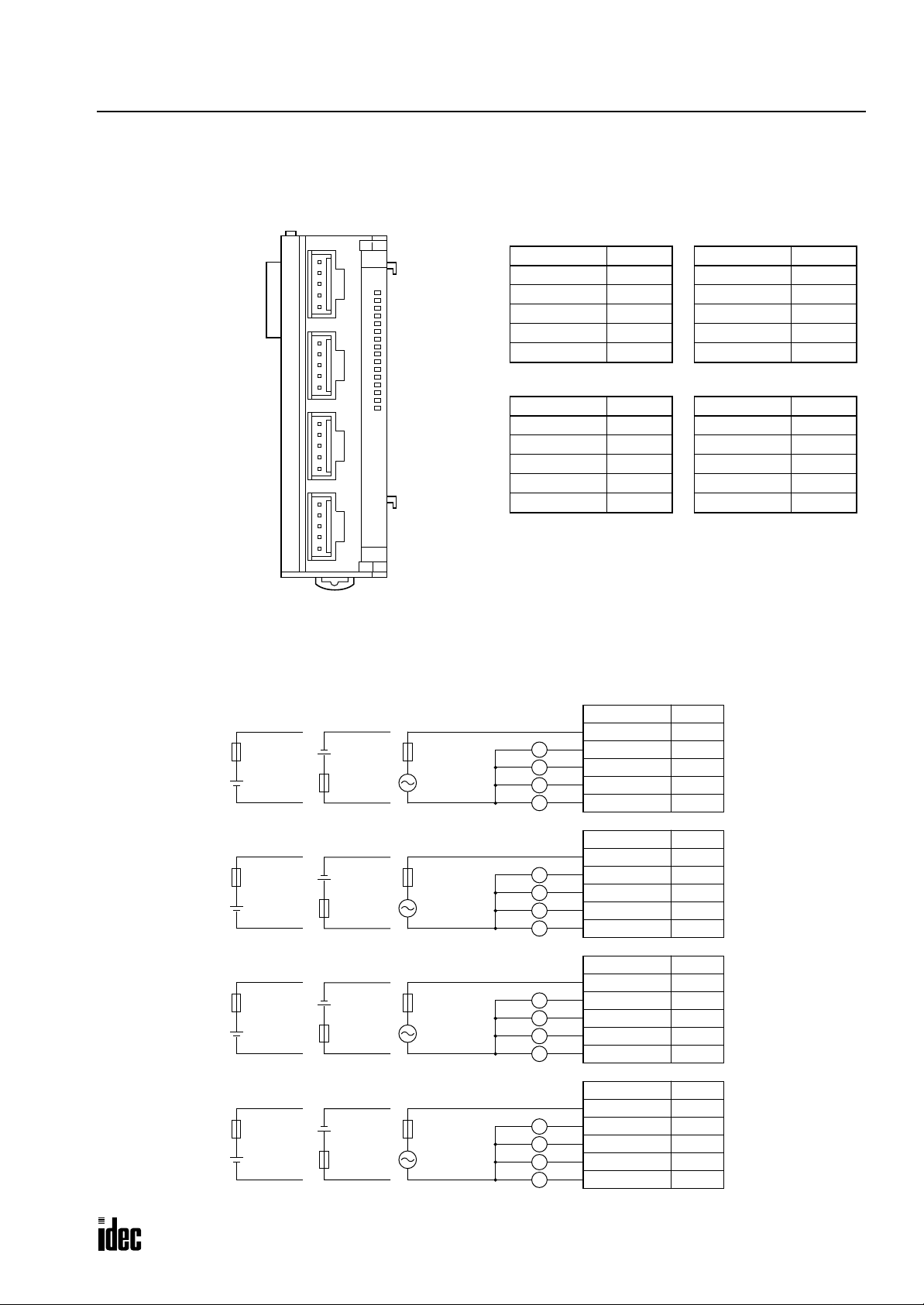
FC3A-R162 (16-point Relay Output Module) — Nylon Connector Type
Phone: 800.894.0412 - Fax: 888.723.4773 - Web: www.clrwtr.com - Email: info@clrwtr.com
Applicable Connectors: VHR-5N (J.S.T. Mfg.)
SVH-21T-P1.1 (J.S.T. Mfg.)
2: MODULE SPECIFICATIONS
CN1
CN2
CN3
CN4
Ry
OUT
0
1
2
3
4
5
6
7
10
11
12
13
14
15
16
17
CN1
Terminal No. Name
CN2
Terminal No. Name
Wiring Schematic
• COM terminals are not connected together internally.
• Terminal numbers are marked on the female connector on the cable.
• For wiring precautions, see page 3-6.
Fuse
+
–
Fuse
+
–
Fuse
+
–
Fuse
+
–
DC
DC
DC
DC
–
+
Fuse
–
+
Fuse
–
+
Fuse
–
+
Fuse
DC
DC
DC
DC
Fuse
AC
Load
Fuse
AC
Load
Fuse
AC
Load
Fuse
AC
Load
1 COM0
2Q0
3Q1
4Q2
5Q3
1 COM1
2Q4
3Q5
4Q6
5Q7
CN1
Terminal No. Name
1 COM0
L
L
L
L
L
L
L
L
L
L
L
L
L
L
L
L
2Q0
3Q1
4Q2
5Q3
CN2
Terminal No. Name
1 COM1
2Q4
3Q5
4Q6
5Q7
CN3
Terminal No. Name
1 COM2
2 Q10
3 Q11
4 Q12
5 Q13
CN4
Terminal No. Name
1 COM3
2 Q14
3 Q15
4 Q16
5 Q17
CN3
Terminal No. Name
1 COM2
2 Q10
3 Q11
4 Q12
5 Q13
CN4
Terminal No. Name
1 COM3
2 Q14
3 Q15
4 Q16
5 Q17
OPENNET CONTROLLER USER’S MANUAL 2-23
Page 39

2: MODULE SPECIFICATIONS
Phone: 800.894.0412 - Fax: 888.723.4773 - Web: www.clrwtr.com - Email: info@clrwtr.com
FC3A-T16K1/FC3A-T16P1 (16-point Transistor Sink and Protect Source Output Modules) — Screw Terminal Type
Applicable Connector: SMSTB2.5/20-ST-5.08 (Phoenix Contact)
FC3A-T16K1
Tr
OUT
0
1
2
3
4
5
6
7
10
11
12
13
14
15
16
17
Terminal No. Name
1Q0
2Q1
3Q2
4Q3
5Q4
6Q5
7Q6
8Q7
9 COM(–)
10 +V
11 Q10
12 Q11
13 Q12
14 Q13
15 Q14
16 Q15
17 Q16
18 Q17
19 COM(–)
20 +V
FC3A-T16P1
Terminal No. Name
1Q0
2Q1
3Q2
4Q3
5Q4
6Q5
7Q6
8Q7
9 COM(+)
10 –V
11 Q10
12 Q11
13 Q12
14 Q13
15 Q14
16 Q15
17 Q16
18 Q17
19 COM(+)
20 –V
Wiring Schematic
• COM terminals are connected together internally.
• Terminal numbers are marked on the terminal block label on the output module.
• For wiring precautions, see page 3-6.
FC3A-T16K1
Terminal No. Name
1Q0
2Q1
3Q2
4Q3
5Q4
6Q5
7Q6
8Q7
9 COM(–)
10 +V
11 Q10
12 Q11
13 Q12
14 Q13
15 Q14
16 Q15
17 Q16
18 Q17
19 COM(–)
20 +V
Fuse
+–
Fuse
+ –
Load
L
L
L
L
L
L
L
L
L
L
L
L
L
L
L
L
Load
L
L
L
L
L
L
L
L
L
L
L
L
L
L
L
L
FC3A-T16P1
Terminal No. Name
1Q0
2Q1
3Q2
4Q3
5Q4
6Q5
7Q6
8Q7
9 COM(+)
10 –V
11 Q10
12 Q11
13 Q12
14 Q13
15 Q14
16 Q15
17 Q16
18 Q17
19 COM(+)
20 –V
2-24 OPENNET CONTROLLER USER’S MANUAL
Page 40

FC3A-T16K3 (16-point Transistor Sink Output Module) — Nylon Connector Type
CN1
Phone: 800.894.0412 - Fax: 888.723.4773 - Web: www.clrwtr.com - Email: info@clrwtr.com
Applicable Connector: VHR-10N (J.S.T. Mfg.)
SVH-21T-P1.1 (J.S.T. Mfg.)
CN1
CN2
Tr
OUT
0
1
2
3
4
5
6
7
10
11
12
13
14
15
16
17
CN2
Wiring Schematic
• COM terminals are connected together internally.
• Terminal numbers are marked on the female connector on the cable.
• For wiring precautions, see page 3-6.
2: MODULE SPECIFICATIONS
Terminal No. Name
1Q0
2Q1
3Q2
4Q3
5Q4
6Q5
7Q6
8Q7
9 COM(–)
10 +V
Terminal No. Name
1 Q10
2 Q11
3 Q12
4 Q13
5 Q14
6 Q15
7 Q16
8 Q17
9 COM(–)
10 +V
Fuse
+ –
Load
L
L
L
L
L
L
L
L
Load
L
L
L
L
L
L
L
L
CN1
Terminal No. Name
1Q0
2Q1
3Q2
4Q3
5Q4
6Q5
7Q6
8Q7
9 COM(–)
10 +V
CN2
Terminal No. Name
1 Q10
2 Q11
3 Q12
4 Q13
5 Q14
6 Q15
7 Q16
8 Q17
9 COM(–)
10 +V
OPENNET CONTROLLER USER’S MANUAL 2-25
Page 41

2: MODULE SPECIFICATIONS
Phone: 800.894.0412 - Fax: 888.723.4773 - Web: www.clrwtr.com - Email: info@clrwtr.com
FC3A-T32K4 (32-point Transistor Sink Output Module) — Nylon Connector Type
Applicable Connector: H18-SHF-AA (J.S.T. Mfg.)
SHF-001T-0.8BS (J.S.T. Mfg.)
CN1
CN1
CN2
Tr
OUT
0
1
2
3
4
5
6
7
10
11
12
13
14
15
16
17
20
21
22
23
24
25
26
27
30
31
32
33
34
35
36
37
Terminal No. Name
Wiring Schematic
• COM terminals are connected together internally.
• Terminal numbers are marked on the female connector on the cable.
• For wiring precautions, see page 3-6.
CN2
18 Q0
17 Q1
16 Q2
15 Q3
14 Q4
13 Q5
12 Q6
11 Q7
10 Q10
9 Q11
8 Q12
7 Q13
6 Q14
5 Q15
4 Q16
3 Q17
2 COM(–)
1+V
Terminal No. Name
18 Q20
17 Q21
16 Q22
15 Q23
14 Q24
13 Q25
12 Q26
11 Q27
10 Q30
9 Q31
8 Q32
7 Q33
6 Q34
5 Q35
4 Q36
3 Q37
2 COM(–)
1+V
Fuse
+ –
Load
L
L
L
L
L
L
L
L
L
L
L
L
L
L
L
L
CN1
Terminal No. Name
18 Q0
17 Q1
16 Q2
15 Q3
14 Q4
13 Q5
12 Q6
11 Q7
10 Q10
9 Q11
8 Q12
7 Q13
6 Q14
5 Q15
4 Q16
3 Q17
2 COM(–)
1+V
CN2
Terminal No. Name
18 Q20
17 Q21
16 Q22
15 Q23
14 Q24
13 Q25
12 Q26
11 Q27
10 Q30
9 Q31
8 Q32
7 Q33
6 Q34
5 Q35
4 Q36
3 Q37
2 COM(–)
1+V
Load
L
L
L
L
L
L
L
L
L
L
L
L
L
L
L
L
2-26 OPENNET CONTROLLER USER’S MANUAL
Page 42
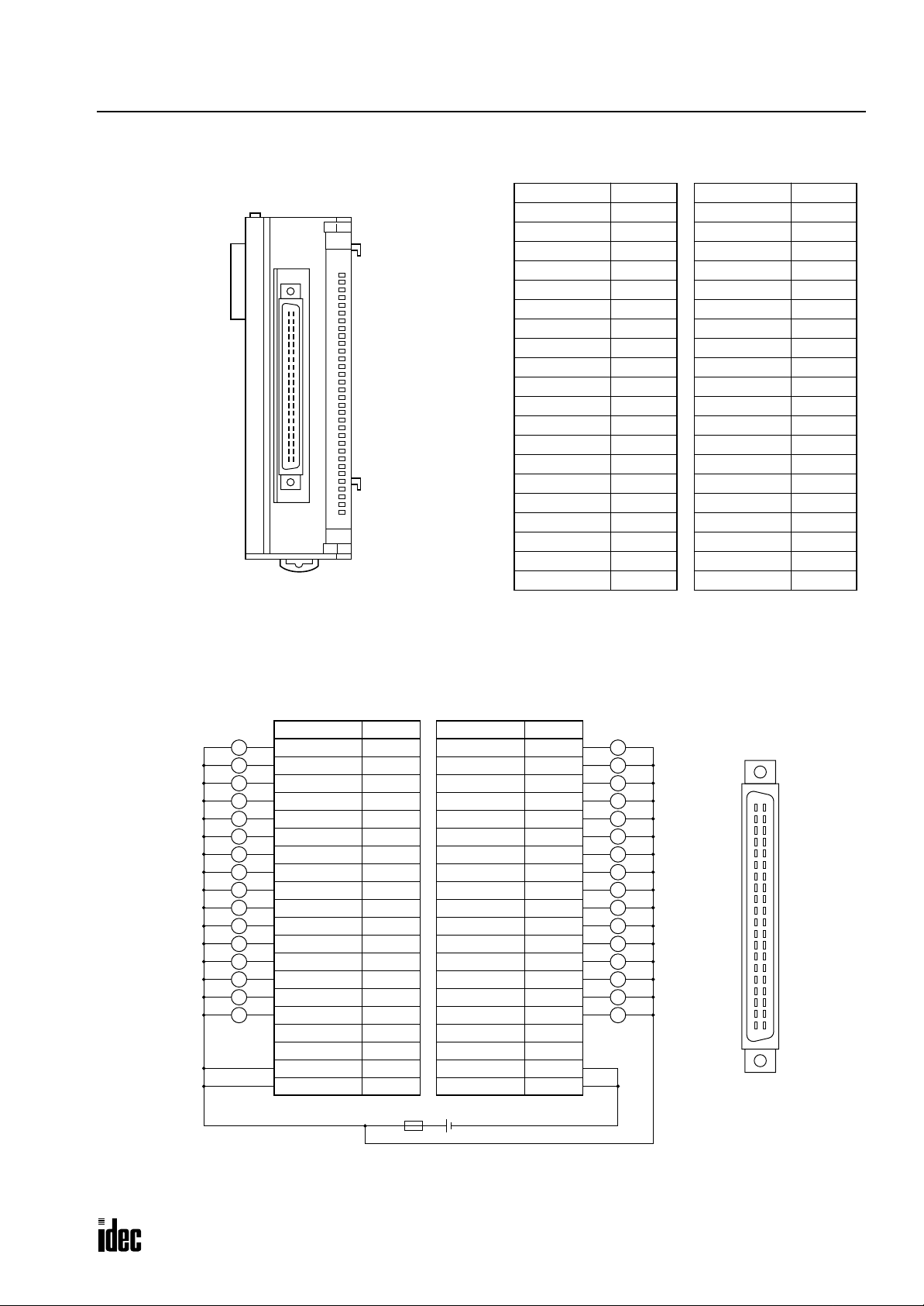
FC3A-T32K5 (32-point Transistor Sink Output Module) — Fujitsu Connector Type
Phone: 800.894.0412 - Fax: 888.723.4773 - Web: www.clrwtr.com - Email: info@clrwtr.com
Applicable Connector: FCN-367J040-AU (Fujitsu)
Terminal No. Name
B20 Q0
Tr
OUT
0
1
2
3
4
5
6
7
10
11
12
13
14
15
16
17
20
21
22
23
24
25
26
27
30
31
32
33
34
35
36
37
B19 Q1
B18 Q2
B17 Q3
B16 Q4
B15 Q5
B14 Q6
B13 Q7
B12 Q10
B11 Q11
B10 Q12
B9 Q13
B8 Q14
B7 Q15
B6 Q16
B5 Q17
B4 NC
B3 NC
B2 +V
B1 +V
2: MODULE SPECIFICATIONS
Terminal No. Name
A20 Q20
A19 Q21
A18 Q22
A17 Q23
A16 Q24
A15 Q25
A14 Q26
A13 Q27
A12 Q30
A11 Q31
A10 Q32
A9 Q33
A8 Q34
A7 Q35
A6 Q36
A5 Q37
A4 NC
A3 NC
A2 COM(–)
A1 COM(–)
Wiring Schematic
• COM terminals are connected together internally.
• Terminal numbers are the front view of the male connector on the output module.
• For wiring precautions, see page 3-6.
Load
L
L
L
L
L
L
L
L
L
L
L
L
L
L
L
L
Terminal No. Name
B20 Q0
B19 Q1
B18 Q2
B17 Q3
B16 Q4
B15 Q5
B14 Q6
B13 Q7
B12 Q10
B11 Q11
B10 Q12
B9 Q13
B8 Q14
B7 Q15
B6 Q16
B5 Q17
B4 NC
B3 NC
B2 +V
B1 +V
Terminal No. Name
A20 Q20
A19 Q21
A18 Q22
A17 Q23
A16 Q24
A15 Q25
A14 Q26
A13 Q27
A12 Q30
A11 Q31
A10 Q32
A9 Q33
A8 Q34
A7 Q35
A6 Q36
A5 Q37
A4 NC
A3 NC
A2 COM(–)
A1 COM(–)
Load
L
L
L
L
L
L
L
L
L
L
L
L
L
L
L
L
B20
B19
B18
B17
B16
B15
B14
B13
B12
B11
B10
B9
B8
B7
B6
B5
B4
B3
B2
B1
A20
A19
A18
A17
A16
A15
A14
A13
A12
A11
A10
A9
A8
A7
A6
A5
A4
A3
A2
A1
Fuse
+ –
Connect the two +V terminals together, and connect the two COM(–) terminals together because
the current capacity of one terminal is exceeded when many outputs are on simultaneously.
OPENNET CONTROLLER USER’S MANUAL 2-27
Page 43

2: MODULE SPECIFICATIONS
T
Phone: 800.894.0412 - Fax: 888.723.4773 - Web: www.clrwtr.com - Email: info@clrwtr.com
Analog Input Module (A/D Converter)
The 12-bit analog input module converts 6 channels of analog signals to digital data of 0 through 4000 which can be processed using advanced instructions such as the coordinate conversion instruction. The analog input module is a functional
module and the converted digital data is stored to a link register, depending on the analog channel and the mounting slot
number of the analog input module in the system setup. The input mode can be selected using the rotary switch to meet
five different analog signal ranges; 0 to 10V, ±10V, 0 to 5V, ±5V, or 4 to 20 mA.
Analog Input Module Type Number
Module Name 6-channel Analog Input Module
Type No. FC3A-AD1261
Parts Description
(5) Expansion Connector
(1) Module ID
(2) Power LED
(6) Rotary Switch
(1) Module ID A/D indicates the analog input module ID.
(2) Power LED Turns on when power is on.
(3) Cable Terminal Screw terminal block
(4) Terminal Label Indicates terminal numbers on the terminal block.
(5) Expansion Connector Connects to CPU and other modules.
(6) Rotary Switch Selects the input mode from five different signal ranges
Rotary Switch Position Input Signal Range Resolution (Input value of LSB)
0 0 to 10V DC 2.5 mV
1 ±10V DC 5 mV
2 0 to 5V DC 1.25 mV
3 ±5V DC 2.5 mV
4 4 to 20 mA DC 4 µA
ype of Protection
+V
(3) Cable Terminal
(4) Terminal Label
Voltage Input
Current Input
COM
250Ω
–V
+
–
Differential
Amplifier
2-28 OPENNET CONTROLLER USER’S MANUAL
Page 44

2: MODULE SPECIFICATIONS
Phone: 800.894.0412 - Fax: 888.723.4773 - Web: www.clrwtr.com - Email: info@clrwtr.com
Analog Input Module Specifications
Type No. FC3A-AD1261
Quantity of Input Channels 6 channels
Terminal Arrangement See page 2-30.
Input Impedance within Signal Range
Maximum Error at 25°C ±0.6% of full scale
Input Error
Digital Resolution 4000 increments
Data Type in Application Program 0 to 4000
Digital Output Reading at Overload 4000
Input Mode Selection Using a rotary switch (see page 2-28)
Type of Input Differential input
Common Mode Characteristics Common mode reject ratio (CMRR) –50 dB
Common Mode Voltage 16V DC
Total Input System Transfer Time 3 msec per channel + 1 scan time maximum
Conversion Time 3 msec per channel
Conversion Method ∑∆ type ADC
Maximum Temporary Deviation during
Electrical Noise Tests and Test Conditions
Conversion Type Successive approximation type
Operating Mode Self-scan
Calibration or Verification to Maintain Rated
Accuracy
Monotonicity Yes
Crosstalk 2 LSB maximum
Non-lineality 0.1% of full scale maximum
Repeatability after Stabilization Time 0.5% of full scale maximum (more than 30 minutes after powerup)
Sample Duration Time 0.1 msec
Sample Repetition Time 0.5 msec
Input Filter 0.2 msec
Dielectric Strength
Cable Shielded cable is recommended for improved noise immunity
Effect of Improper Input Connection Permanent damage may be caused
Terminal Block Insertion/Removal Durability 100 times minimum
Internal Current Draw 120 mA (24V DC)
Weight (approx.) 230g
Temperature Coefficient ±0.013 %/°C (typical)
Maximum Error over Full
Temperature Range
Voltage input: 1 MΩ minimum
Current input: 250Ω
±1% of full scale
3% maximum of full scale at 500V impulse test
Impossible
500V AC between input channel and power supply under normal operating conditions
OPENNET CONTROLLER USER’S MANUAL 2-29
Page 45

2: MODULE SPECIFICATIONS
Phone: 800.894.0412 - Fax: 888.723.4773 - Web: www.clrwtr.com - Email: info@clrwtr.com
Analog Input Module Terminal Arrangement
FC3A-AD1261 (6-channel Analog Input Module) — Screw Terminal Type
Applicable Connector: SMSTB2.5/20-ST-5.08 (Phoenix Contact)
A/D
PCW
Terminal No. Channel Name
1
2 +I (current)
Channel 0
+V (voltage)
3 COM (–V, –I)
4
5 +I (current)
Channel 1
+V (voltage)
6 COM (–V, –I)
7
8 +I (current)
Channel 2
+V (voltage)
9 COM (–V, –I)
10
11 +I (current)
Channel 3
+V (voltage)
12 COM (–V, –I)
13
14 +I (current)
Channel 4
+V (voltage)
15 COM (–V, –I)
16
17 +I (current)
Channel 5
+V (voltage)
18 COM (–V, –I)
19 — NC
20 — NC
Wiring Diagram
Voltage Input
Analog
Voltage
Output
Device
0 to 10V, ±10V, 0 to 5V, ±5V
(+)
(–)
Analog
Input
Module
+V
+I
COM
Current Input
Analog
Current
Output
Device
4 to 20 mA
(+)
Unused Channel
Analog
Input
Module
+V
+I
(–)
COM
Analog
Input
Module
+V
+I
COM
Connect +V and COM
terminals of unused
channels together.
Example: When converting an analog voltage input (0 to 10V, ±10V, 0 to 5V, or ±5V DC) using channel 4, connect the
signal to terminals 13 and 15. When the analog input module is the second functional module installed in the
Controller
system, the converted digital value is stored to link register L204. When connecting an analog current input (4
OpenNet
to 20 mA), connect terminals +I and +V together, and connect the input across terminals +I and COM as shown in the middle above.
For wiring schematic and precautions, see page 3-8.
Notes:
• Before mounting the analog input module, first set the rotary switch to meet the required analog input range. After setting
the rotary switch, power up the CPU and other modules.
• The COM (–V, –I) terminal of each channel is independent from each other.
• Connect the +V and COM terminals of unused channels together. Connecting these terminals together will reduce the AD
conversion time in the analog input module (by approximately 10% for every unused slot).
2-30 OPENNET CONTROLLER USER’S MANUAL
Page 46

2: MODULE SPECIFICATIONS
T
Phone: 800.894.0412 - Fax: 888.723.4773 - Web: www.clrwtr.com - Email: info@clrwtr.com
Analog Output Module (D/A Converter)
The 12-bit analog output module converts digital data of 0 through 4000 to 2 channels of analog signals. The analog output
module is a functional module and the digital data for conversion must be stored to a link re gister , depending on the analog
channel and the mounting slot number of the analog output module in the system setup. The output mode can be selected
using the rotary switch to meet five different analog signal ranges; 0 to 10V, ±10V, 0 to 5V, ±5V, or 4 to 20 mA.
Analog Output Module Type Number
Module Name 2-channel Analog Output Module
Type No. FC3A-DA1221
Parts Description
(5) Expansion Connector
(1) Module ID
(2) Power LED
(6) Rotary Switch
(1) Module ID D/A indicates the analog output module ID.
(2) Power LED Turns on when power is on.
(3) Cable Terminal Screw terminal block
(4) Terminal Label Indicates terminal numbers on the terminal block.
(5) Expansion Connector Connects to CPU and other modules.
(6) Rotary Switch Selects the output mode from five different signal ranges
ype of Protection
Rotary Switch
Position
0 0 to 10V DC 2.5 mV 0V
1 ±10V DC 5 mV –10V
2 0 to 5V DC 1.25 mV 0V
3 ±5V DC 2.5 mV –5V
4 4 to 20 mA DC 4 µA 4 mA
+V
Output Signal Range
Resolution
(Output value of LSB)
(3) Cable Terminal
(4) Terminal Label
Output when
Stopped
Voltage Output
–V
OPENNET CONTROLLER USER’S MANUAL 2-31
Current Output
COM
Page 47

2: MODULE SPECIFICATIONS
Phone: 800.894.0412 - Fax: 888.723.4773 - Web: www.clrwtr.com - Email: info@clrwtr.com
Analog Output Module Specifications
Type No. FC3A-DA1221
Quantity of Output Channels 2 channels
Terminal Arrangement See page 2-33.
Maximum Error at 25°C ±0.6% of full scale
Output Error
Digital Resolution 4000 increments
Data Type in Application Program 0 to 4000
Total Output System Transfer Time 3 msec + 1 scan time maximum
Settling Time after Maximum Range Change 3 msec
Overshoot 0%
Maximum Temporary Deviation during Electrical
Noise Tests and Test Conditions
Output Voltage Drop 1% maximum of full scale
Calibration or Verification to Maintain Rated
Accuracy
Maximum Capacitive Load Not applicable
Maximum Inductive Load Not applicable
Monotonicity Yes
Crosstalk 2 LSB maximum
Non-lineality 0.1% of full scale maximum
Repeatability after Stabilization Time 0.5% of full scale maximum (more than 30 minutes after powerup)
Output Ripple 1 LSB maximum
Output Response at Power Up and Down Output returns to the lower limit value within 1 msec
Output Mode Selection and Output Value of LSB Using a rotary switch (see page 2-31)
Load Impedance in Signal Range
Maximum Allowed Output Voltage
Dielectric Strength
Cable Shielded cable is recommended for improved noise immunity
Quantity of Channels per COM 1 channel per COM
Effect of Improper Output Connection Permanent damage may be caused
Terminal Block Insertion/Removal Durability 100 times minimum
Applicable Load Type Resistive load
Internal Current Draw 120 mA (24V DC)
Weight (approx.) 230g
Temperature Coefficient ±0.013 %/°C (typical)
Maximum Error over Full
Temperature Range
±1% of full scale
3% maximum of full scale at 500V impulse test
Impossible
Voltage output: 2 kΩ minimum
Current output: 250Ω (300Ω maximum)
Voltage output: ±12V DC (between output terminals)
Current output: ±12V DC (between output terminals)
500V AC between output channel and power supply under normal
operating conditions
2-32 OPENNET CONTROLLER USER’S MANUAL
Page 48

Analog Output Module Terminal Arrangement
Phone: 800.894.0412 - Fax: 888.723.4773 - Web: www.clrwtr.com - Email: info@clrwtr.com
FC3A-DA1221 (2-channel Analog Output Module) — Screw Terminal Type
Applicable Connector: SMSTB2.5/20-ST-5.08 (Phoenix Contact)
2: MODULE SPECIFICATIONS
Terminal No. Channel
D/A
PCW
1
2 COM (GND)
3
4 COM (GND)
5
6 COM (GND)
7
8 COM (GND)
9
10 COM (GND)
11
12 COM (GND)
13
14 COM (GND)
15
16 COM (GND)
17
18 COM (GND)
19
20 COM (GND)
Channel 0
Channel 1
Rotary Switch
Position
0
1
2
3
4
0
1
2
3
4
Name
Voltage output (0 to 10V)
Voltage output (±10V)
Voltage output (0 to 5V)
Voltage output (±5V)
Current output (4 to 20mA)
Voltage output (0 to 10V)
Voltage output (±10V)
Voltage output (0 to 5V)
Voltage output (±5V)
Current output (4 to 20mA)
Wiring Example:
Suppose that an analog output module is the sixth functional module installed in the
OpenNet Controller system. To gener-
ate a 4V analog output voltage from channel 1 using the 0 to 5V output range, set the rotary switch to 2 and store a digital
value of 3200 to link register L601, which is assigned to channel 1 of the sixth functional module.
Because 5V × 3200/4000 = 4V, digital value 3200 is converted to an analog value of 4V and outputted to terminals 15 and
16 of the analog output module.
For wiring schematic and precautions, see page 3-8.
Notes:
• Before mounting the analog output module, first set the rotary switch to meet the required analog output range. After set-
ting the rotary switch, power up the CPU and other modules.
• The COM (GND) terminals of each channel are connected together internally.
OPENNET CONTROLLER USER’S MANUAL 2-33
Page 49

2: MODULE SPECIFICATIONS
Phone: 800.894.0412 - Fax: 888.723.4773 - Web: www.clrwtr.com - Email: info@clrwtr.com
Expansion Power Supply Module
The FC3A-EA1 expansion power supply module is used to mount more than seven I/O and functional modules. When a
maximum of 15 I/O modules are mounted, the number of I/O points is expanded from 224 to 480 maximum.
Whether an expansion module is used or not, seven functional modules such as analog I/O, DeviceNet slave, and LON-
WORKS interface modules can be mounted at the maximum in either the normal or expansion slots.
Expansion Power Supply Module Type Number
Module Name Expansion Power Supply Module
Type No. FC3A-EA1
The expansion power supply module is supplied with the following attachments:
Cable/Connector 1 pc, cable length 1m (3.28 ft.)
Contact 3 pcs, used to extend the cable length
Parts Description
(6) Expansion Connector
1NC
NC
2
24V
3
0V
4
5
(1) Module ID
(2) Power LED
(3) Terminal Cover
(4) Terminal Label
(5) Cable Connector
(1) Module ID EXP indicates the expansion power supply module ID.
(2) Power LED Turns on when power is on.
(3) Terminal Cover The terminal cover flips open to the right.
(4) Terminal Label Indicates terminal numbers.
(5) Cable Connector Nylon connector (5-pin)
(6) Expansion Connector Connects to CPU and other modules.
Expansion Power Supply Module Mounting Position
Mount the expansion power supply module in the eighth slot.
Do not mount the expansion power supply module in any other slot than the eighth, otherwise correct allocation of
I/O and link register numbers may not occur.
CPU Module
7 modules (I/O and functional)
Expansion Power Supply Module
A maximum of 7 functional modules can be mounted in any of 15 slots
8 modules (I/O and functional)
2-34 OPENNET CONTROLLER USER’S MANUAL
Page 50

2: MODULE SPECIFICATIONS
Phone: 800.894.0412 - Fax: 888.723.4773 - Web: www.clrwtr.com - Email: info@clrwtr.com
Expansion Power Supply Module Specifications
Type No. FC3A-EA1
Rated Power Voltage 24V DC
Allowable Voltage Range 19 to 30V DC (including ripple)
Dielectric Strength Between power terminal and FG: 1,000V AC, 1 minute
Maximum Input Current 5A at 24V DC
Internal Current Draw 30 mA (24V DC)
Allowable Momentary Power
Interruption
Insulation Resistance Between power terminal and FG: 10 MΩ minimum (500V DC megger)
Inrush Current 50A (total of inrush currents into CPU and expansion power supply modules)
Ground Grounding resistance: 100Ω maximum
Grounding Wire UL1015 AWG22
Power Supply Wire UL1015 AWG22
Effect of Improper Power
Supply Connection
Weight (approx.) 180g
10 msec (24V DC), Level PS-2 (EN61131)
Reverse polarity: No operation, no damage
Improper voltage or frequency: Permanent damage may be caused
Improper lead connection: Permanent damage may be caused
Power Supply Wiring to Expansion Power Supply Module
Connect a 24V DC power source to the 24V and 0V pins on the expansion power supply module connector.
Use the same power source for the CPU module to power the expansion po wer supply module. The inrush current to
both the CPU and expansion power supply module is 50A total. AC power source cannot be used. Internal current draw of
the expansion power supply module is 30 mA.
Connector
1: NC
Power Voltage: 24V DC
Inrush Current: 50A
(same power source for CPU)
– +
Fuse
Ground
The length of the attached cable is 1 meter (3.28 feet). When a longer cable is needed, use the attached contacts to connect
the cable to the attached connector.
2: NC
3: 24V DC (red)
4: 0V (blue)
5: FG (green)
OPENNET CONTROLLER USER’S MANUAL 2-35
Page 51

2: MODULE SPECIFICATIONS
Phone: 800.894.0412 - Fax: 888.723.4773 - Web: www.clrwtr.com - Email: info@clrwtr.com
Remote I/O Master Module
The remote I/O master module is used to configure a remote I/O network to increase I/O points at remote stations. The
OpenNet Controller uses the INTERBUS network for communication with a maximum of 32 remote I/O slave stations.
For the remote I/O slave stations, IDEC’s SX5S communication I/O terminals are used. When using 32 SX5S modules
with 16 input or output points, a total of 512 I/O points can be distributed to 32 remote slave stations at the maximum.
For details about the remote I/O system, see page 24-1.
Remote I/O Master Module Type Number and Weight
Module Name Remote I/O Master Module
Type No. FC3A-SX5SM1
Weight (approx.) 200g
Parts Description
(1) Module ID
(5) Status LED
(2) FG Terminal
(3) Connector 1 (V.24 Interface)
D-sub 9-pin Male Connector
(4) Connector 2 (REMOTE OUT)
D-sub 9-pin Female Connector
(1) Module ID FC3A-SX5SM1 indicates the remote I/O master module ID.
(2) FG Terminal Frame ground
(3) Connector 1 V.24 Interface for monitoring the communication line using CMD
(CMD is a software program to run on Windows 3.1/95 for configuration, monitoring,
and diagnosis supplied by Phoenix Contact.)
(4) Connector 2 REMOTE OUT for connecting a communication cable to the REMOTE IN connector
on a remote I/O slave module
(5) Status LED Turns on to indicate the following status:
RDY/RUN READY/RUN
NO ERR
REMOTE_BUS_ERR
FAIL
BSA BUS_SEGMENT_DISABLED
PF MODULE_ERROR
HF HOST_HARDWARE_FAULT
LOCAL_BUS_ERR
CONTROLLER_ERR
WATCHDOG_ERR
HARDWARE_FAULT
2-36 OPENNET CONTROLLER USER’S MANUAL
Page 52

2: MODULE SPECIFICATIONS
Phone: 800.894.0412 - Fax: 888.723.4773 - Web: www.clrwtr.com - Email: info@clrwtr.com
Remote I/O Master Module General Specifications
Type No. FC3A-SX5SM1
Power Voltage Supplied by the CPU module
Dielectric Strength Between power terminal on the CPU module and FG: 500V AC, 1 minute
Insulation Resistance
Internal Current Draw Approx. 142 mA (24V DC) See Power Consumption on page 2-4.
FG Terminal M3 screw (Tightening torque: 0.6 to 1.0 N·m)
Ground Grounding resistance: 100Ω maximum
Grounding Wire UL1015 AWG22, UL1007 AWG18
Weight (approx.) 200g
Remote I/O Master Module Function Specifications
Network Protocol INTERBUS
Transmission Speed 500 kbps
Transmission Distance
Quantity of Nodes 32 remote I/O slave stations maximum
I/O Points per Node 128 points maximum (64 inputs and 64 outputs)
Branch Levels 16 maximum (INTERBUS device levels 0 through 15)
Remote I/O Connector D-sub 9-pin female connector on the remote I/O master module
Network Cable INTERBUS cable
V.24 Interface Connector D-sub 9-pin male connector on the remote I/O master module
V.24 Interface Cable Serial straight cable
Electrostatic Discharge
Severity Level
Between REMOTE OUT terminal and FG: 10 MΩ minimum (500V DC megger)
Between V.24 Interface terminal and FG: 10 MΩ minimum (500V DC megger)
Between remote I/O master and remote bus station: 400m maximum
Between remote bus stations: 400m maximum
Remote bus total length: 12.8 km maximum
ESD-3 (network interface)
See page 24-11.
OPENNET CONTROLLER USER’S MANUAL 2-37
Page 53

2: MODULE SPECIFICATIONS
Phone: 800.894.0412 - Fax: 888.723.4773 - Web: www.clrwtr.com - Email: info@clrwtr.com
DeviceNet Slave Module
The OpenNet Controller can be linked to DeviceNet networks. For communication through the DeviceNet network, the
DeviceNet slave module is available.
For details about the DeviceNet slave module and DeviceNet communication system, see page 25-1.
DeviceNet Slave Module Type Number and Weight
Module Name DeviceNet Slave Module
Type No. FC3A-SX5DS1
Weight (approx.) 180g
Parts Description
(5) Expansion Connector
(1) Module ID
(4) Status LED
(2) DIP Switch
(3) Connector
(1) Module ID FC3A-SX5DS1 indicates the DeviceNet slave module ID.
(2) DIP Switch 10-pole DIP switch for setting the node address (MAC ID: media access control identi-
fier), data rate, output hold/load off, and physical port number
(3) Connector Network interface connector for connecting an input communication cable
(4) Status LED Indicates operating status
POW
MNS
IO
POWER
Green ON: Power is on
MODULE/NETWORK STATUS
OFF: Duplicate MAC ID test not completed
Green Flash: Normal operation (not communicating with master)
Green ON: Normal operation (communicating with master)
Red Flash: Minor fault (e.g. timeout)
Red ON: Critical fault (e.g. duplicate MAC ID)
I/O STATUS
Green ON: Normal operation
Red ON: Fault
(5) Expansion Connector Connects to CPU and other modules.
2-38 OPENNET CONTROLLER USER’S MANUAL
Page 54

2: MODULE SPECIFICATIONS
Phone: 800.894.0412 - Fax: 888.723.4773 - Web: www.clrwtr.com - Email: info@clrwtr.com
LONWORKS Interface Module
The OpenNet Controller can be linked to LONWORKS networks. For communication through the LONWORKS network, the
LONWORKS interface module is available.
For details about the LONWORKS interface module and LONWORKS communication system, see page 26-1.
LONWORKS Interface Module Type Number and Weight
Module Name LONWORKS Interface Module
Type No. FC3A-SX5LS1
Weight (approx.) 180g
Parts Description
(6) Expansion Connector
(1) Module ID
(5) Status LED
SERVICE
REQUEST
LON
(2) FG Terminal
(3) Service Request Button
(4) Connector
(1) Module ID FC3A-SX5LS1 indicates the LONWORKS interface module ID.
(2) FG Terminal Frame ground
(3) Service Request Button Pushbutton used for network management
(4) Connector Network interface connector for connecting an input communication cable
(5) Status LED Indicates operating status
POW
RUN
POWER
Green ON: Power is on
RUN
Green ON: Normal operation
COM_ERROR
ERR
Red ON: Communication error
OFF: Normal
I/O
I/O_ERROR
Red ON: Access error to the CPU through I/O bus
SERVICE
SER
Yellow ON: Application program not configured
Yellow Flash: Network management not configured
(6) Expansion Connector Connects to CPU and other modules.
OPENNET CONTROLLER USER’S MANUAL 2-39
Page 55

2: MODULE SPECIFICATIONS
Phone: 800.894.0412 - Fax: 888.723.4773 - Web: www.clrwtr.com - Email: info@clrwtr.com
Dimensions
All OpenNet Controller modules have the same profile for consistent mounting on a DIN rail.
CPU Module
558.5
1104.5
1.8
100
Digital I/O, Analog I/O, Expansion Power Supply, Remote I/O Master, DeviceNet Slave, and
ONWORKS Interface Modules
L
35 8.5
110 1.8
1.8
4.5
100
Digital I/O, analog I/O, expansion power supply, remote I/O master, Devicenet Slave,
and L
ONWORKS interface modules have the same outside dimensions.
Example: The following figure illustrates a system setup consisting of a remote I/O master module, a CPU module, and
three I/O modules.
195
3535 35 35
All dimensions in mm.
110
55
V.24 InterfaceREMOTE OUT
idec
2-40 OPENNET CONTROLLER USER’S MANUAL
Page 56

3: INSTALLATION AND WIRING
Phone: 800.894.0412 - Fax: 888.723.4773 - Web: www.clrwtr.com - Email: info@clrwtr.com
Introduction
This chapter describes the methods and precautions for installing and wiring OpenNet Controller modules.
Before starting installation and wiring, be sure to read “Safety Precautions” in the beginning of this manual and under-
stand precautions described under Warning and Caution.
Warning
Caution
• Turn power off to the
nance, and inspection of the OpenNet Controller. Failure to turn power off may cause electrical
shocks or fire hazard.
• Emergency stop and interlocking circuits must be configured outside the OpenNet Controller. If
such a circuit is configured inside the OpenNet Controller, failure of the OpenNet Controller may
cause disorder of the control system, damage, or accidents.
• Special expertise is required to install, wire, program, and operate the OpenNet Controller. People
without such expertise must not use the OpenNet Controller.
• Prevent metal fragments and pieces of wire from dropping inside the OpenNet Controller hous-
ing. Put a cover on the OpenNet Controller modules during installation and wiring. Ingress of
such fragments and chips may cause fire hazard, damage, or malfunction.
OpenNet Controller before starting installation, removal, wiring, mainte-
Installation Location
The OpenNet Controller must be installed correctly for optimum performance.
The environment for using the OpenNet Controller is “Pollution degree 2.” Use the OpenNet Controller in environments of
pollution degree 2 (according to IEC 60664-1).
Make sure that the operating temperature does not drop below 0°C or exceed 55°C. If the temperature does exceed 55°C,
use a fan or cooler.
Mount the OpenNet Controller on a vertical plane.
To eliminate excessive temperature build-up, provide ample venti-
lation. Do not install the OpenNet Controller near, and especially
above, any device which generates considerable heat, such as a
heater, transformer , or lar ge capacity resistor. The relative humidity
should be above 30% and below 95%.
The OpenNet Controller should not be exposed to excessive dust,
dirt, salt, direct sunlight, vibrations, or shocks. Do not use the
OpenNet Controller in an area where corrosive chemicals or flam-
mable gases are present. The modules should not be exposed to
chemical, oil, or water splashes.
OPENNET CONTROLLER USER’S MANUAL 3-1
BNL6
Mounting Clip
Page 57

3: INSTALLATION AND WIRING
Phone: 800.894.0412 - Fax: 888.723.4773 - Web: www.clrwtr.com - Email: info@clrwtr.com
Assembling Modules
Caution
• Assemble OpenNet Controller modules together before mounting the modules onto a DIN rail.
Attempt to assemble modules on a DIN rail may cause damage to the modules.
• When using analog input or output modules, first set the rotary switch on the side of the module
to the desired input/output mode before assembling the module. The rotary switch cannot be
changed after the module has been assembled. For the operation modes of analog input and output modules, see pages 2-28 and 2-31.
The following example demonstrates the procedure for assembling a CPU module and an I/O module together.
1. When assembling an analog input or output module, set the
rotary switch to select the desired operation mode. Use a small
flat screwdriver to turn the rotary switch.
2. Place the CPU module and I/O module side by side. Put the
expansion connectors together for easy alignment.
4
5
3
6
2
7
1
0
3. With the expansion connectors aligned correctly, press the
CPU module and I/O module together until the latches click to
attach the modules together firmly.
4. Press the end plate to each side of the module assembly. A pair
of end plates are supplied with each CPU module.
3-2 OPENNET CONTROLLER USER’S MANUAL
Page 58

Disassembling Modules
Phone: 800.894.0412 - Fax: 888.723.4773 - Web: www.clrwtr.com - Email: info@clrwtr.com
3: INSTALLATION AND WIRING
Caution
• Remove the OpenNet Controller modules from the DIN rail before disassembling the modules.
Attempt to disassemble modules on a DIN rail may cause damage to the modules.
1. If the modules are mounted on a DIN rail, first remove the
modules from the DIN rail as described below on this page.
2. Press the blue unlatch button on top of the module to disengage
the latches. With the button held depressed, pull the modules
apart as shown.
3. To remove the end plate, push in the square button at the top
and bottom of the end plate from the front and pull the end
plate from the module row as shown. Attach the end plate to the
CPU module, if required.
Mounting on DIN Rail
Caution
1. Fasten the DIN rail to a panel using screws firmly.
2. Pull out the clamp from each OpenNet Controller module, and put
the groove of the module on the DIN rail. Press the modules
towards the DIN rail and push in the clamps as shown on the right.
3. Use BNL6 mounting clips on both sides of the OpenNet Controller
modules to prevent moving sideways.
• Install the OpenNet Controller modules according to instructions described in this user’s manual.
Improper installation will result in falling, failure, or malfunction of the OpenNet Controller.
• Mount the OpenNet Controller modules on a 35-mm-wide DIN rail.
Applicable DIN rail: IDEC’s BAA1000 (1000mm/39.4” long)
Removing from DIN Rail
1. Insert a flat screwdriver into the slot in the clamp.
2. Pull out the clamps from the modules
Groove
Groove
35-mm-wide DIN Rail
35-mm-wide DIN Rail
Clamp
Clamp
35-mm-wide DIN Rail
3. Turn the OpenNet Controller modules bottom out.
OPENNET CONTROLLER USER’S MANUAL 3-3
Clamp
Page 59

3: INSTALLATION AND WIRING
Phone: 800.894.0412 - Fax: 888.723.4773 - Web: www.clrwtr.com - Email: info@clrwtr.com
Installation in Control Panel
The OpenNet Controller modules are designed for installation in equipment. Do not install the OpenNet Controller modules outside equipment.
The environment for using the
pollution degree 2 (according to IEC 60664-1).
OpenNet Controller is “Pollution degree 2. ” Use the OpenNet Controller in en vironments of
When installing the
OpenNet Controller modules in a control panel, take the convenience of operation and maintenance,
and resistance against environments into consideration.
20 mm minimum
0
1
2
3
4
5
6
7
8
9
10
11
12
13
14
40 mm
minimum
20 mm minimum
15
40 mm
16
17
minimum
Front Panel
20 mm minimum
80 mm
minimum
20 mm minimum
Wiring Duct
Mounting Direction
Mount the OpenNet Controller modules horizontally on a vertical plane as shown above. Keep a sufficient spacing around
the OpenNet Controller modules to ensure proper ventilation. When the ambient temperature is 40°C or below, the Open-
Net Controller
modules can also be mounted upright on a horizontal plane as shown at left below.
Allowable Mounting Direction
at 40°C or below
Incorrect
Mounting
Direction
10111213141516
17
9
Incorrect
Mounting
Direction
012345678
3-4 OPENNET CONTROLLER USER’S MANUAL
Page 60

Input Wiring
Phone: 800.894.0412 - Fax: 888.723.4773 - Web: www.clrwtr.com - Email: info@clrwtr.com
3: INSTALLATION AND WIRING
Caution
• Terminal name “NC” means “No Connection.” Do not connect input or any other wiring to NC
terminals.
• Separate the input wiring from the output line, power line, and motor line.
• Use UL1015AWG22 or UL1007AWG18 wires for input wiring.
DC Source Input DC Sink Input
DC
1
IN
2
3
10
11
12
13
14
15
16
17
18
19
20
0
1
4
2
3
5
4
5
6
6
7
7
10
11
8
12
13
9
14
15
16
17
+24V
DC
2-wire Sensor
+24V
DC
NPN
–
+
2-wire Sensor
PNP
DC
1
IN
2
3
0
1
4
2
3
5
4
5
6
6
7
7
10
11
8
12
13
9
14
15
10
16
17
11
12
13
–
+
14
15
16
17
18
19
20
AC Input
10
11
12
13
14
15
16
17
18
19
20
AC
1
IN
2
3
0
1
4
2
3
5
4
5
6
6
7
7
8
9
OPENNET CONTROLLER USER’S MANUAL 3-5
Page 61

3: INSTALLATION AND WIRING
Phone: 800.894.0412 - Fax: 888.723.4773 - Web: www.clrwtr.com - Email: info@clrwtr.com
Output Wiring
Caution
• Terminal name “NC” means “No Connection.” Do not connect output or any other wiring to NC terminals.
• If relays or transistors in the OpenNet Controller output modules should fail, outputs may remain on or off. For
output signals which may cause heavy accidents, provide a monitor circuit outside the OpenNet Controller.
• Connect a fuse to the output module, selecting a fuse appropriate for the load.
• Use UL1015AWG22 or UL1007AWG18 wires
for output wiring.
• When driving loads which generate noise, such
as electromagnetic contactors and solenoid
valves, use a surge absorber for AC power or a
diode for DC power.
AC
Power
Load Load
L
Output
Terminal
Surge
Absorber
Relay Output Transistor Sink Output
(+)
DC
Power
L
(–)
Output
Terminal
Diode
Insert a fuse compatible
with the load.
+
Load
Load
Load
Load
+
Load
Load
Load
Load
+
Load
Load
Load
Load
+
Load
Load
Load
Load
10
11
12
13
14
15
16
17
18
19
20
Load
Ry
1
OUT
2
3
0
1
4
2
3
5
4
5
6
6
7
7
10
11
8
12
13
9
14
15
16
17
Insert a fuse
compatible
with the load.
Load
Load
Load
Load
Load
Load
Load
Load
Load
Load
Load
Load
Load
+
Load
Load
10
11
12
13
14
15
16
17
18
19
20
Tr
1
OUT
2
3
0
1
4
2
3
5
4
5
6
6
7
7
10
11
8
12
13
9
14
15
16
17
Power supply
for source output:
+
3-6 OPENNET CONTROLLER USER’S MANUAL
Page 62

3: INSTALLATION AND WIRING
Phone: 800.894.0412 - Fax: 888.723.4773 - Web: www.clrwtr.com - Email: info@clrwtr.com
Output Wiring for Application in Europe
When equipment containing the OpenNet Controller is intended for use in European countries, insert an IEC 60127approved fuse to each output of ev ery output module for protection against ov erload or short-circuit. This is required when
exporting equipment containing the OpenNet Controller to Europe.
Example: FC3A-R161 Relay Output Module Wiring
Fuse
Ry
1
10
11
12
13
14
15
16
17
18
19
20
OUT
2
3
0
1
4
2
3
5
4
5
6
6
7
7
10
11
8
12
13
9
14
15
16
17
+
Load
Load
Load
Load
+
Load
Load
Load
Load
+
Load
Load
Load
Load
+
Load
Load
Load
Load
Data Link Wiring
• For wiring the data link cable to the RS485 terminals on the CPU
module, use a two-core twisted pair shielded cable with a minimum
core diameter of 0.9 mm.
• Separate the data link cable from the output line, power line, and
motor line.
Cable
Shield
A
B
Shield
HSC
OUT
AB
A
RS485
B
G
+24V
0V
OPENNET CONTROLLER USER’S MANUAL 3-7
Page 63

3: INSTALLATION AND WIRING
Phone: 800.894.0412 - Fax: 888.723.4773 - Web: www.clrwtr.com - Email: info@clrwtr.com
Analog Input/Output Wiring
When using an analog input or output module, connect analog signals and ground wire as shown below.
• For wiring analog input or output module, use a two-core twisted pair shielded cable with a minimum core diameter of
0.9 mm. Connect the shield to a proper frame ground (grounding resistance 100Ω maximum).
• Connect the FG terminals of the 24V DC power supply and the CPU module to the ground (grounding resistance 100Ω
maximum). The ground connection improves the stability of analog/digital conversion.
• Terminal numbers are marked on the terminal block label on the input/output module.
• For analog input and output module specifications, see pages 2-28 and 2-31.
Wiring Schematic
Analog Voltage Input (rotary switch set to 0 through 3)
Analog Input Module
Analog
Voltage
Output
Device
0 to 10V,
±10V,
0 to 5V,
±5V
Connect +V and
COM terminals of
unused channels
Analog
Voltage
Input
Device
0 to 10V DC
Analog
Voltage
Input
Device
0 to 10V DC
+
–
together.
+
–
+
–
Terminal No. Channel Name
1
2+I
3 COM
4
5+I
6 COM
7
8+I
9 COM
10
11 +I
12 COM
13
14 +I
15 COM
16
17 +I
18 COM
19 — NC
20 — NC
FG FG
Analog Output Module
Term
Chan
No.
1
2 COM
3
4 COM
5
Ch 0
6 COM
7
8 COM
9
10 COM
11
12 COM
13
14 COM
15
Ch 1
16 COM
17
18 COM
19
20 COM
FG FG
Ch 0
Ch 1
Ch 2
Ch 3
Ch 4
Ch 5
Rotary
Sw.
0
1
2
3
4
0
1
2
3
4
Name
0-10V
±10V
0-5V
±5V
4-20mA
0-10V
±10V
0-5V
±5V
4-20mA
+V
+V
+V
+V
+V
+V
Analog Current Input (rotary switch set to 4)
Analog Input Module
Analog
Current
Output
Device
0 to 20 mA
Connect +V and
COM terminals of
unused channels
+
–
together.
Terminal No. Channel Name
1
2+I
3 COM
4
5+I
6 COM
7
8+I
9 COM
10
11 +I
12 COM
13
14 +I
15 COM
16
17 +I
18 COM
19 — NC
20 — NC
Analog Current Output (rotary switch set to 4)Analog Voltage Output (rotary switch set to 0)
Analog Output Module
Analog
Current
Input
Device
0 to 20 mA
Analog
Current
Input
Device
0 to 20 mA
Term
No.
1
2 COM
3
4 COM
5
6 COM
7
+
–
+
–
8 COM
9
10 COM
11
12 COM
13
14 COM
15
16 COM
17
18 COM
19
20 COM
Chan
Ch 0
Ch 1
Rotary
Sw.
0
1
2
3
4
0
1
2
3
4
+V
Ch 0
+V
Ch 1
+V
Ch 2
+V
Ch 3
+V
Ch 4
+V
Ch 5
Name
0-10V
±10V
0-5V
±5V
4-20mA
0-10V
±10V
0-5V
±5V
4-20mA
3-8 OPENNET CONTROLLER USER’S MANUAL
Page 64

Power Supply
Phone: 800.894.0412 - Fax: 888.723.4773 - Web: www.clrwtr.com - Email: info@clrwtr.com
3: INSTALLATION AND WIRING
Caution
• Use a power supply of the rated value. Use of a wrong power supply may cause fire hazard.
• The allowable power voltage range for the OpenNet Controller is 19 to 30V DC. Do not use the
OpenNet Controller on any other voltage.
• If the power voltage turns on or off very slowly between 5 and 15V DC, the OpenNet Controller
may run and stop repeatedly between these voltages. If failure or disorder of the control system,
damage, or accidents may be caused, provide a measure for prevention using a voltage monitoring circuit outside the OpenNet Controller.
• Use an IEC 60127-approved fuse on the power line outside the OpenNet Controller. This is
required when exporting equipment containing OpenNet Controller to Europe.
Power Supply Voltage
The allowable power voltage range for the
OpenNet Controller is 19 to 30V DC.
Power failure detection voltage depends on the quantity of used input and output points. Basically, power failure is
detected when the power voltage drops below 19V DC, stopping operation to prevent malfunction.
A momentary power interruption for 10 msec or less is not recognized as a power failure at the rated voltage of 24V DC.
Inrush Current at Powerup
When the
OpenNet Controller is powered up, an inrush current of 40A or
less flows at the rated voltage of 24V DC.
Power Supply Wiring
Use a stranded wire of UL1015 AWG22 or UL1007 AWG18 for power
supply wiring. Make the power supply wiring as short as possible.
Run the power supply wiring as far away as possible from motor lines.
HSC
OUT
Grounding (CPU Module)
To prevent electrical shocks or malfunctioning due to noise, connect the
FG terminal to the ground using a wire of UL1015 AWG22 or UL1007
AWG18 (grounding resistance 100Ω maximum). Do not connect the
24V DC
+
_
A
RS485
B
G
+24V
0VCOM A B Z
grounding wire in common with the grounding wire of motor equipment.
Grounding (Remote I/O Master and LONWORKS Interface Modules)
Connect the FG terminal to the ground using a wire of UL1015 AWG22 or UL1007 AWG18 (grounding resistance 100Ω
maximum) and a ring-shape wire terminal. Tighten the M3 FG terminal screw to a torque of 0.6 to 1.0 N·m. Do not connect the grounding wire in common with the grounding wire of motor equipment.
Note: For power supply wiring to the expansion power supply module, see page 2-35.
OPENNET CONTROLLER USER’S MANUAL 3-9
Page 65

3: INSTALLATION AND WIRING
Phone: 800.894.0412 - Fax: 888.723.4773 - Web: www.clrwtr.com - Email: info@clrwtr.com
Terminal Connection
Caution
• Make sure that the operating conditions and environments are within the specification values.
• Be sure to connect the grounding wire to a proper ground, otherwise electrical shocks may be
caused.
• Do not touch live terminals, otherwise electrical shocks may be caused.
• Do not touch terminals immediately after power is turned off, otherwise electrical shocks may be
caused.
Ferrules, Crimping Tool, and Screwdriver for Phoenix Terminal Blocks
The screw terminal block can be wired with or without using ferrules on the end of cable. Applicable ferrules for the Phoenix terminal blocks and crimping tool for the ferrules are listed below. The screwdriver is used for tightening the screw ter minals on the OpenNet Controller modules. These ferrules, crimping tool, and screwdriver are made by Phoenix Contact
and are available from Phoenix Contact.
T ype numbers of the ferrules, crimping tool, and screwdriver listed below are the type numbers of Phoenix Contact. When
ordering these products from Phoenix Contact, specify the Order No. and quantity listed below.
Ferrule Order No.
Quantity of Cables Cable Size Phoenix Type Order No. Pcs./Pkt.
For 1-cable connection
For 2-cable connection
UL1007 AWG18 AI 1-8 RD 32 00 03 0 100
UL1015 AWG22 AI 0,5-8 WH 32 00 01 4 100
UL1007 AWG18 AI-TWIN 2 x 1-8 RD 32 00 81 0 100
UL1015 AWG22 AI-TWIN 2 x 0,5-8 WH 32 00 93 3 100
Crimping Tool and Screwdriver Order No.
Tool Name Phoenix Type Order No. Pcs./Pkt.
Crimping Tool CRIMPFOX UD 6 12 04 43 6 1
Screwdriver SZS 0,6 x 3,5 12 05 05 3 10
Screw Terminal Tightening Torque 0.5 to 0.6 N·m
If ferrules other than listed above are used, the ferrule may come in contact with the terminal block cover. Then, remove
the terminal block cover from the module.
3-10 OPENNET CONTROLLER USER’S MANUAL
Page 66

4: OPERATION BASICS
Phone: 800.894.0412 - Fax: 888.723.4773 - Web: www.clrwtr.com - Email: info@clrwtr.com
Introduction
This chapter describes general information about setting up the basic OpenNet Controller system for programming, starting and stopping OpenNet Controller operation, and introduces simple operating procedures from creating a user program
using WindLDR on a computer to monitoring the OpenNet Controller operation.
Connecting OpenNet Controller to PC (1:1 Computer Link System)
The OpenNet Controller can be connected to an IBM PC or compatible computer in two ways.
Computer Link through RS232C Port 1 or Port 2
When connecting a W indo ws computer to the RS232C port 1 or port 2 on the OpenNet Controller CPU module, enable the
maintenance mode for the RS232C port.
To enable the maintenance mode for the RS232C port 1, set the DIP switch 2 to OFF.
To enable the maintenance mode for the RS232C port 2, set the DIP switch 3 to OFF.
To set up a 1:1 computer link system, connect a computer to the OpenNet Controller using the computer link cable 4C
(FC2A-KC4C).
0
1
2
3
4
5
6
7
8
9
10
11
12
RS232C Port 2
13
14
15
16
17
Computer Link Cable 4C
FC2A-KC4C
O
DIP
Switch
N
123
3m (9.84 ft.) long
RS232C
D-sub 9-pin Female Connector
RS232C Port 1
Computer Link through RS485 Port
When connecting a Windows computer to the RS485 port on the
OpenNet Controller CPU module, enable the mainte-
nance mode for the RS485 port.
To enable the maintenance mode for the RS485, set the DIP switch 1 to OFF.
To set up a 1:1 computer link system, connect a computer to the OpenNet Controller using the computer link cable 6C
(FC2A-KC6C). An AC adapter is needed to supply 5V DC power to the RS232C/RS485 converter on the computer link
cable 6C. For the applicable output plug of the AC adapter, see page A-5.
Computer Link Cable 6C
FC2A-KC6C
2m (6.56 ft.) long
AC Adapter
RS485
O
DIP
Switch
N
123
Cable
Shield
HSC
OUT
0
1
2
AB
3
4
5
A
6
7
8
9
RS485
10
11
B
12
13
14
15
16
G
17
+24V
0V
RS232C
D-sub 9-pin
Female Connector
OPENNET CONTROLLER USER’S MANUAL 4-1
Page 67

4: OPERATION BASICS
Phone: 800.894.0412 - Fax: 888.723.4773 - Web: www.clrwtr.com - Email: info@clrwtr.com
Start/Stop Operation
This section describes operations to start and stop the OpenNet Controller and to use the stop and reset inputs.
Caution
• Make sure of safety before starting and stopping the
the OpenNet Controller may cause machine damage or accidents.
OpenNet Controller. Incorrect operation on
Start/Stop Schematic
The start/stop circuit of the OpenNet Controller consists of three blocks; power supply, M8000 (start
control special internal relay), and stop/reset inputs.
Each block can be used to start and stop the OpenNet
Controller
while the other two blocks are set to run
Power
Supply
M8000
Start Control
WindLDR
Stop
Input
Reset
Input
Start
PLC
the OpenNet Controller.
Start/Stop Operation Using WindLDR
The OpenNet Controller can be started and stopped using WindLDR run on a PC connected to the OpenNet Controller CPU
module. When the PLC Start button is pressed in the dialog box shown below, start control special internal relay M8000
is turned on to start the OpenNet Controller. When the PLC Stop button is pressed, M8000 is turned off to stop the Open-
Net Controller
1. Connect the PC to the OpenNet Controller, start WindLDR, and power up the OpenNet Controller. See page 4-1.
2. Check that a stop input is not designated using Configure > Function Area Settings > Run/Stop. See page 5-1.
Note: When a stop input is designated, the OpenNet Controller cannot be started or stopped by turning start control special
internal relay M8000 on or off.
3. Select Online from the WindLDR menu bar, then select Download Program. Or, click the download icon .
OpenNet Download Program dialog box appears.
.
4. Click the PLC Start button to start operation, then the start control special internal relay M8000 is turned on.
5. Click the PLC Stop button to stop operation, then the start control special internal relay M8000 is turned off.
The PLC operation can also be started and stopped while
WindLDR is in the monitor mode. To access the Start or Stop
button, select Online > Monitor and select Online > PLC Status > Run/Stop Status.
Note: Special internal relay M8000 is a keep type internal relay and stores the status when power is turned off. M8000
retains its previous status when power is turned on again. However, when the backup battery is dead, M8000 loses the
stored status, and can be turned on or off as programmed when the OpenNet Controller is powered up. The selection is
made in Configure > Function Area Settings > Run/Stop > Run/Stop Selection at Memory Backup Error. See page 5-2.
The backup duration is approximately 30 days (typical) at 25°C after the backup battery is fully charged.
4-2 OPENNET CONTROLLER USER’S MANUAL
Page 68

Start/Stop Operation Using the Power Supply
Phone: 800.894.0412 - Fax: 888.723.4773 - Web: www.clrwtr.com - Email: info@clrwtr.com
The OpenNet Controller can be started and stopped by turning power on and off.
1. Power up the OpenNet Controller to start operation. See page 4-1.
4: OPERATION BASICS
2. If the
OpenNet Controller does not start, check that start control special internal relay M8000 is on using WindLDR. If
M8000 is off, turn it on. See page 4-2.
3. Turn power on and off to start and stop operation.
Note: If M8000 is off, the OpenNet Controller does not start operation when power is turned on. To start operation, turn
power on, and turn M8000 on by clicking the Start button in WindLDR.
The response time of the OpenNet Controller at powerup depends on such factors as the contents of the user program, data
link usage, and system setup. The table below shows an approximate time delay before starting operation after powerup.
Response time when no data link and remote I/O modules are used:
Program Size After powerup, the CPU starts operation in
1K words Approx. 1 second
4K words Approx. 2 seconds
8K words Approx. 3 seconds
16K words Approx. 5 seconds
Order of Powerup and Powerdown
To ensure I/O data transfer, power up the I/O modules first, followed by the CPU module or power up
the CPU and I/O modules at the same time. When
I/O Module Power
CPU Module Power
ON
OFF
ON
OFF
shutting down the system, power do wn the CPU first,
followed by I/O modules or power down the CPU
and I/O modules at the same time.
0 sec or more 0 sec or more
Start/Stop Operation Using Stop Input and Reset Input
Any input I0 through I597 can be designated as a stop or reset input using Function Area Settings. The procedure for
selecting stop and reset inputs is described on page 5-1.
Note: When using a stop and/or reset input to start and stop operation, make sure that start control special internal relay
M8000 is on. If M8000 is off, then the CPU does not start operation when the stop or reset input is turned off. M8000 is
not turned on or off when the stop and/or reset input is turned on or off.
When a stop or reset input is turned on during program operation, the CPU stops operation, the RUN LED is turned off,
and all outputs are turned off.
The reset input has priority over the stop input.
System Statuses
The system statuses during running, stop, reset, and restart after stopping are listed below:
Internal Relays, Shift Registers,
Mode Outputs
Run Operating Operating Operating Operating Operating
Stop (Stop input ON) OFF Unchanged Unchanged Unchanged Unchanged
Reset (Reset input ON) OFF OFF/Reset to zero OFF/Reset to zero Reset to zero Reset to zero
Restart Unchanged Unchanged OFF/Reset to zero Reset to preset Unchanged
Note: Link registers used as outputs are turned off like outputs.
Counters, Data Registers
Keep Type Clear Type
Timer
Current Value
Link Register
(Note)
OPENNET CONTROLLER USER’S MANUAL 4-3
Page 69

4: OPERATION BASICS
Phone: 800.894.0412 - Fax: 888.723.4773 - Web: www.clrwtr.com - Email: info@clrwtr.com
Simple Operation
This section describes how to edit a simple program using WindLDR on a computer , transfer the program from WindLDR on
the PC to the OpenNet Controller, run the program, and monitor the operation on WindLDR.
Connect the
Sample User Program
Create a simple program using WindLDR. The sample program performs the following operation:
Start WindLDR
From the Start menu of Windows, select Programs > WindLDR > WindLDR.
WindLDR starts and a blank ladder editing screen appears with menus and tool bars shown on top of the screen.
OpenNet Controller to the computer as described on page 4-1.
When only input I0 is turned on, output Q0 is turned on.
When only input I1 is turned on, output Q1 is turned on.
When both inputs I0 and I1 are turned on, output Q2 flashes in 1-sec increments.
Rung No. Input I0 Input I1 Output Operation
01 ON OFF Output Q0 is turned ON.
02 OFF ON Output Q1 is turned ON.
03 ON ON Output Q2 flashes in 1-sec increments.
Edit User Program Rung by Rung
Start the user program with the LOD instruction by inserting a NO contact of
input I0.
1. Click the Normally Open contact icon .
When the mouse pointer is placed on an icon, the name of the icon is indicated.
4-4 OPENNET CONTROLLER USER’S MANUAL
Page 70

2. Move the mouse pointer to the first column of the first line where you
Phone: 800.894.0412 - Fax: 888.723.4773 - Web: www.clrwtr.com - Email: info@clrwtr.com
want to insert a NO contact, and click the left mouse button.
The Normally Open dialog box appears.
3. Enter I0 in the Tag Name field, and click OK.
A NO contact of input I0 is programmed in the first column of the first ladder line.
Next, program the ANDN instruction by inserting a NC contact of input I1.
4: OPERATION BASICS
4. Click the Normally Closed contact icon .
The mouse pointer is indicated with the name of the icon “Normally Closed.”
5. Move the mouse pointer to the second column of the first ladder line where you want to insert a NC contact, and click
the left mouse button.
The Normally Closed dialog box appears.
6. Enter I1 in the Tag Name field, and click OK.
A NC contact of input I1 is programmed in the second column of the first ladder line.
At the end of the first ladder line, program the OUT instruction by inserting a NO coil of output Q0.
7. Click the Output coil icon .
The mouse pointer is indicated with the name of the icon “Output.”
8. Move the mouse pointer to the third column of the first ladder line where you want to insert an output coil, and click
the left mouse button.
The Output dialog box appears.
9. Enter Q0 in the Tag Name field, and click OK.
A NO output coil of output Q0 is programmed in the third column of the first ladder line. This completes programming for
rung 1.
Continue programming for rungs 2 and 3 by repeating the similar procedures.
OPENNET CONTROLLER USER’S MANUAL 4-5
Page 71

4: OPERATION BASICS
Phone: 800.894.0412 - Fax: 888.723.4773 - Web: www.clrwtr.com - Email: info@clrwtr.com
A new rung is inserted by pressing the Enter key while the cursor is on the preceding rung. A new rung can also be
inserted by selecting Edit > Append > Rung. When completed, the ladder program looks like below.
Now, save the file with a new name.
10. From the menu bar, select F
ile > Save As and type TEST01.LDR in the File Name field. Change the Folder or Drive
as necessary.
Click OK, and the file is saved in the selected folder and drive.
Download Program
You can download the user program from WindLDR running on a PC to the OpenNet Controller.
From the
the Download button. The user program is downloaded to the OpenNet Controller.
WindLDR menu bar, select Online > Download Program. The Download Program Dialog shows, then click
Download Button
Note: When downloading a user program, all values and selections in the Function Area Settings are also downloaded to the
OpenNet Controller. For Function Area Settings, see pages 5-1 through 5-18.
4-6 OPENNET CONTROLLER USER’S MANUAL
Page 72

4: OPERATION BASICS
Phone: 800.894.0412 - Fax: 888.723.4773 - Web: www.clrwtr.com - Email: info@clrwtr.com
Monitor Operation
Another powerful function of WindLDR is to monitor the PLC operation on the PC. The input and output statuses of the
sample program can be monitored in the ladder diagram.
From the
When both inputs I0 and I1 are on, the ladder diagram on the monitor screen looks as follows:
WindLDR menu bar, select Online > Monitor.
Rung 01: When both inputs I0 and I1 are on, output Q0 is turned
off.
Rung 02: When both inputs I0 and I1 are on, output Q1 is turned
off.
Rung 03: When both input I0 and I1 are on, internal relay M10 is
turned on.
M8121 is the 1-sec clock special internal relay.
While M10 is on, output Q2 flashes in 1-sec increments.
Quitting WindLDR
When you have completed monitoring, you can quit WindLDR either directly from the monitor screen or from the editing
screen. In both cases, from the menu bar select File > Exit WindLDR.
OPENNET CONTROLLER USER’S MANUAL 4-7
Page 73

4: OPERATION BASICS
Phone: 800.894.0412 - Fax: 888.723.4773 - Web: www.clrwtr.com - Email: info@clrwtr.com
4-8 OPENNET CONTROLLER USER’S MANUAL
Page 74

5: SPECIAL FUNCTIONS
Phone: 800.894.0412 - Fax: 888.723.4773 - Web: www.clrwtr.com - Email: info@clrwtr.com
Introduction
The OpenNet Controller features special functions such as stop/reset inputs, run/stop selection at memory backup error,
keep designation for internal relays, shift registers, counters, and data registers. These functions are programmed using the
Function Area Settings menu. Also included in the Function Area Settings are module ID selection and run/stop operation
upon disparity, input filter, catch input, high-speed counter, key matrix input, and user program read/write protection.
This chapter describes these special functions. Constant scan and memory card features are also described in this chapter.
Although included in the Function Area Settings, the data link communication function is detailed on pages 21-1 through
21-12.
Caution
• Since all Function Area Settings relate to the user program, the user program must be down-
loaded to the OpenNet Controller after changing any of these settings.
Stop Input and Reset Input
As described on page 4-2, the OpenNet Controller can be started and stopped using a stop input or reset input, which can
be designated from the Function Area Settings menu. When the designated stop or reset input is turned on, the OpenNet
Controller
Since these settings relate to the user program, the user program must be downloaded to the OpenNet Controller after
changing any of these settings.
Programming WindLDR
1. From the
2. Select the Run/Stop tab.
Stop Input: Click the check box on the left and type a desired input number I0 through I597 in the input number field.
Reset Input: Click the check box on the left and type a desired reset number I0 through I597 in the input number field.
stops operation. For the system statuses in the stop and reset modes, see page 4-3.
WindLDR menu bar, select Configure > Function Ar ea Settings. The Function Area Setting dialog box
appears.
This example designates input I0
as a stop input and input I12 as
a reset input.
Default: No stop and reset inputs are designated.
OPENNET CONTROLLER USER’S MANUAL 5-1
Page 75

5: SPECIAL FUNCTIONS
Phone: 800.894.0412 - Fax: 888.723.4773 - Web: www.clrwtr.com - Email: info@clrwtr.com
Run/Stop Selection at Memory Backup Error
Start control special internal relay M8000 maintains its status when the CPU is powered down. After the CPU has been off
for a period longer than the battery backup duration, the data designated to be maintained during power failure is broken.
The Run/Stop Selection at Memory Backup Error dialog box is used to select whether to start or stop the CPU when
attempting to restart operation after the “keep” data in the CPU RAM has been lost.
Since this setting relates to the user program, the user program must be downloaded to the OpenNet Controller after changing this setting.
Programming WindLDR
1. From the WindLDR menu bar, select Configure > Function Area Settings. The Function Area Setting dialog box
appears.
2. Select the Run/Stop tab.
Run (Default): Click the button on the left to start the CPU at memory backup error.
Stop: Click the button on the left to stop the CPU when attempting to start at memory backup error.
When the CPU does not start because of the Stop selection, the CPU can not be started alone, then the
CPU can still be started by sending a start command from WindLDR. For start/stop operation, see page
4-2.
This example designates to allow
to start operation when the
“keep” data has been lost.
Default: Run
5-2 OPENNET CONTROLLER USER’S MANUAL
Page 76

5: SPECIAL FUNCTIONS
Phone: 800.894.0412 - Fax: 888.723.4773 - Web: www.clrwtr.com - Email: info@clrwtr.com
Keep Designation for Internal Relays, Shift Registers, Counters, and Data Registers
The statuses of internal relays and shift register bits are usually cleared at startup. It is also possible to designate all or a
block of consecutive internal relays or shift register bits as “keep” types. Counter current values and data register values
are usually maintained at powerup. It is also possible to designate all or a block of consecutive counters and data registers
as “clear” types.
When the CPU is stopped, these statuses and values are maintained. When the CPU is reset by turning on a designated
reset input, these statues and values are cleared despite the settings in the Keep dialog box shown below. The keep/clear
settings in this dialog box have effect when restarting the CPU.
Since these settings relate to the user program, the user program must be downloaded to the OpenNet Controller after
changing any of these settings.
Programming WindLDR
1. From the WindLDR menu bar, select Configure > Function Area Settings. The Function Area Setting dialog box
appears.
2. Select the Keep tab. The Keep page appears.
OPENNET CONTROLLER USER’S MANUAL 5-3
Page 77

5: SPECIAL FUNCTIONS
Phone: 800.894.0412 - Fax: 888.723.4773 - Web: www.clrwtr.com - Email: info@clrwtr.com
Internal Relay ‘Keep’ Designation
All Clear: All internal relay statuses are cleared at startup (default).
All Keep: All internal relay statuses are maintained at startup.
Keep Range: A designated area of internal relays are maintained at startup. Enter the start “keep” number in the
left field and the end “keep” number in the right field. The start “keep” number must be smaller
than or equal to the end “keep” number.
Valid internal relay numbers are M0 through M2557. Special internal relays cannot be designated.
Start Keep Number
End Keep Number (≥ Start Keep Number)
When a range of M50 - M100 is designated as shown in the example above, M50 through M100
are keep types, M0 through M49 and M101 through M2557 are clear types.
Shift Register ‘Keep’ Designation
All Clear: All shift register bit statuses are cleared at startup (default).
All Keep: All shift register bit statuses are maintained at startup.
Keep Range: A designated area of shift register bits are maintained at startup. Enter the start “keep” number in
the left field and the end “keep” number in the right field. The start “keep” number must be
smaller than or equal to the end “keep” number. Valid shift register bit numbers are R0 through
R255.
When a range of R17 - R32 is designated, R17 through R32 are keep types, R0 through R16 and
R33 through R255 are clear types.
Counter ‘Clear’ Designation
All Keep: All counter current values are maintained at startup (default).
All Clear: All counter current values are cleared at startup.
Clear Range: A designated area of counter current values are cleared at startup. Enter the start “clear” number
in the left field and the end “clear” number in the right field. The start “clear” number must be
smaller than or equal to the end “clear” number. Valid counter numbers are C0 through C255.
When a range of C0 - C10 is designated, C0 through C10 are clear types, and C11 through C255
are keep types.
Data Register ‘Clear’ Designation
All Keep: All data register values are maintained at startup (default).
All Clear: All data register values are cleared at startup.
Clear Range: A designated area of data register values are cleared at startup. Enter the start “clear” number in
the left field and the end “clear” number in the right field. The start “clear” number must be
smaller than or equal to the end “clear” number. Valid data register numbers are D0 through
D7999. Special data registers cannot be designated.
When a range of D100 - D7999 is designated, D0 through D99 are keep types, and D100 through
D7999 are clear types.
5-4 OPENNET CONTROLLER USER’S MANUAL
Page 78

5: SPECIAL FUNCTIONS
Phone: 800.894.0412 - Fax: 888.723.4773 - Web: www.clrwtr.com - Email: info@clrwtr.com
Module ID Selection and Run/Stop Operation upon Disparity
The CPU module can be mounted with a maximum of seven I/O modules and functional modules without using an expansion power supply module. When using an expansion power supply module, a maximum of 15 modules can be mounted
with one CPU module.
The Module ID function is used to register the type of module installed in each slot. If the information in the memory
about the module ID for each slot is found different from the actual module installed at startup, the CPU can be stopped to
run in order to prevent accidents.
Since these settings relate to the user program, the user program must be downloaded to the OpenNet Controller after
changing any of these settings.
Programming WindLDR
1. From the WindLDR menu bar, select Configure > Function Area Settings. The Function Area Setting dialog box
appears.
2. Select the Module ID tab.
3. Click Module 01 through Module 15 in the Module Selection list box to select a slot number to mount a module.
Digital I/O and functional modules are numbered Module 01 through Module 15 starting with the module mounted next to
the CPU module.
4. Select a module type in the Module T ype list box.
Not Set: Module type is not selected for the selected slot.
Digital I/O: A digital I/O module is selected for the selected slot.
Functional Module: A functional module is selected for the selected slot; such as an analog I/O or OpenNet I/F module.
5. Click the check box under Module ID Operation Selection.
Check in the Box (default): The CPU starts to run even if actual modules differ from the module ID settings.
No Check in the Box: The CPU does not start to run when actual modules differ from the module ID settings.
(Terminal and connector type difference has no effect.)
When the check box is unchecked and the CPU does not start, the ERROR LED is turned on and I/O bus error is caused
(error code 0800h). Then, replace the I/O and functional modules to match the information specified in the user program,
and retry to start the CPU.
OPENNET CONTROLLER USER’S MANUAL 5-5
Page 79

5: SPECIAL FUNCTIONS
Phone: 800.894.0412 - Fax: 888.723.4773 - Web: www.clrwtr.com - Email: info@clrwtr.com
Input Filter
The input filter function is used to reject input noises. The catch input function described in the next section is used to
receive short input pulses. On the contrary, the input filter function ignores short input pulses when the OpenNet Controller
is used with input signals containing noises.
Normal inputs require a pulse width of the filter value plus one scan time to receive input signals. Input filter values have
effect on the performance of the catch inputs, key matrix inputs, and digital read instruction.
Since these settings relate to the user program, the user program must be downloaded to the OpenNet Controller after
changing any of these settings.
Programming WindLDR
1. From the WindLDR menu bar, select Configure > Function Area Settings. The Function Area Setting dialog box
appears.
2. Select the Filter/Catch tab.
Module Number Selection
Module 1 to 15
Module Number Selection Select the module number from 1 through 15 to designate input filter (or catch input)
Input Filter Time Selection
Groups of 8 inputs
0, 0.5, 1, 2, 4, 8, 16, 32 msec
Default: 4 msec
Catch Input Rising/Falling
Edge Selection
No effect on the input filter
function. Module number 1 is the input module mounted next to the CPU module.
Module number 2 is the second from the CPU module, and so on.
Input Filter Time Selection Input filter time is selected in groups of eight inputs. For example, input numbers of
module number 1 containing 32 inputs are divided into four groups:
IN_FLT0: I0 through I7 (only IN_FLT0 has effect on catch inputs)
IN_FLT1: I10 through I17
IN_FLT2: I20 through I27
IN_FLT3: I30 through I37
Select an input filter value from 0, 0.5, 1, 2, 4, 8, 16, or 32 msec for each input group.
Default: 4 msec
Catch Input Rising/Falling Edge Selection — No effect on the input filter
Input Filter Values and Input Operation
Depending on the selected values, the input filter has three response areas to receive or reject input signals.
Input reject area: Input signals are ignored and not received (one-third of the selected filter value or less).
Input indefinite area: Input signals may be received or ignored.
Input accept area: Input signals are received (the selected filter value or higher).
Example: Rejecting Input Pulses of 2.6 msec at Inputs 0 through 7
To accept input pulses of 8 msec plus 1 scan time using normal inputs, select 8 msec in the Input Filter Time Selection
area for IN_FLT0. Then, since 8/3 approximately equals 2.6 msec, input pulses shorter than 2.6 msec are rejected.
2.6 msec 8 msec + 1 scan
Reject AcceptInputs I0 to I7
5-6 OPENNET CONTROLLER USER’S MANUAL
Indefinite
Page 80

5: SPECIAL FUNCTIONS
Phone: 800.894.0412 - Fax: 888.723.4773 - Web: www.clrwtr.com - Email: info@clrwtr.com
Catch Input
The catch input function is used to receive short pulses from sensor outputs regardless of the scan time. Input pulses
shorter than one scan time can be received. First eight inputs of ev ery DC input module can be designated to catch a rising
or falling edge of short input pulses. The Function Area Settings is used to designate first eight inputs of every DC input
module as a catch input or normal input.
Input signals to normal input terminals are read when the END instruction is executed at the end of a scan.
Since these settings relate to the user program, the user program must be downloaded to the OpenNet Controller after
changing any of these settings.
Catch Input Specifications
Minimum Turn ON Pulse Width 40 µsec (when the input filter is set to 0 msec)
Minimum Turn OFF Pulse Width 150 µsec (when the input filter is set to 0 msec)
Programming WindLDR
1. From the WindLDR menu bar, select Configure > Function Area Settings. The Function Area Setting dialog box
appears.
2. Select the Filter/Catch tab.
Module Number Selection
Module 1 to 15
Module Number Selection Select the module number from 1 through 15 to designate catch input or input filter
Input Filter Time Selection
Groups of 8 inputs
0, 0.5, 1, 2, 4, 8, 16, 32 msec
Default: 4 msec
Catch Input Rising/Falling
Edge Selection
Normal Input (default)
Catch Input Falling Edge
Catch Input Rising Edge
function. Module number 1 is the input module mounted next to the CPU module.
Module number 2 is the second from the CPU module, and so on.
Input Filter Time Selection Input filter time is selected in groups of eight inputs. For example, input numbers of
module number 1 are divided into four groups:
IN_FLT0: I0 through I7 (only IN_FLT0 has effect on catch inputs)
IN_FLT1, IN_FLT2, and IN_FLT3 have no effect on catch inputs.
Select an input filter value from 0, 0.5, 1, 2, 4, 8, 16, or 32 msec for IN_FLT0 of each
DC input module.
Default: 4 msec
Catch Input Rising/Falling Edge Selection
Select catch input of rising or falling edge or normal input for the first eight inputs of
each DC input module.
Default: Normal Input
OPENNET CONTROLLER USER’S MANUAL 5-7
Page 81

5: SPECIAL FUNCTIONS
Phone: 800.894.0412 - Fax: 888.723.4773 - Web: www.clrwtr.com - Email: info@clrwtr.com
Catching Rising Edge of Input Pulse
Note 1
Actual Input
Input Relay
(I0 to I7)
ON
OFF
ON
OFF
END
Processed
Note 2
One Scan
Catching Falling Edge of Input Pulse
Note 1
Actual Input
Input Relay
(I0 to I7)
ON
OFF
ON
OFF
END
Processed
Note 2
Note 1: When two or more pulses enter within one scan, subsequent pulses are ignored.
Note 2: The pulse entering at the timing shown above cannot be used as pulse inputs for counters and shift registers.
Example: Counting Catch Input Pulses
This example demonstrates a program to count short pulses using the catch input function.
Reset
CNT C2
I0
100
Pulse
I1
Designate input I1 as a catch input
Input I0 is used as a reset input for adding counter C2.
Input I1 is designated as a catch input using the Function Area Settings.
Counter C2 counts short-pulse inputs to input I1.
Note: When a catch input is used as a pulse input to a counter, the repeat cycle period of
the pulse inputs must be more than 2 scan times.
Example: Maintaining Catch Input
When a catch input is received, the input relay assigned to a catch input is turned on for only one scan. This e xample demonstrates a program to maintain a catch input status for more than one scan.
Input I0 is designated as a catch input using the Function Area Settings.
I0
I1 M0
Catch input
M0
M0
Note: To catch as short inputs as possible, select 0 msec in the Input Filter Time Selection field.
5-8 OPENNET CONTROLLER USER’S MANUAL
When input I0 is turned on, internal relay M0 is turned on, and M0 is maintained in the
self-holding circuit.
When NC input I1 is turned off, the self-holding circuit is unlatched, and M0 is turned off.
M0 is used as an input condition for the subsequent program instructions.
Page 82

5: SPECIAL FUNCTIONS
Phone: 800.894.0412 - Fax: 888.723.4773 - Web: www.clrwtr.com - Email: info@clrwtr.com
High-speed Counter
This section describes the high-speed counter function to count many pulse inputs within one scan. Using the built-in 16bit high-speed counter, the OpenNet Controller counts up to 65535 high-speed pulses from a rotary encoder or proximity
switch without regard to the scan time, compares the current value with a preset value, and turns on the output when the
current value exceeds the preset value. This function can be used for simple motor control or to measure lengths of objects.
The high-speed counter can be used in the rotary encoder mode or dual-pulse reversible counter mode, which can be
selected using the Function Area Settings in WindLDR.
The CPU module has screw terminals 1 through 5 dedicated to the high-speed counter. The high-speed counter counts up
or down input pulses to terminals 2 (phase A or CW) and 3 (phase B or CCW), and turns on the comparison output at terminal 5 (comparison output) when the current value exceeds the preset v alue. The comparison output does not go on when
the preset value is reached, but goes on when another input pulse enters after reaching the preset v alue. Use of the compar ison output is selected using the Function Area Settings.
When the input to terminal 4 (phase Z or reset-to-zero input) is turned on, the current value is reset to zero.
Three special data registers and seven special internal relays are assigned to control and monitor the high-speed counter
operation. The high-speed counter current value is stored in data register D8045 and is updated every scan. The value
stored in D8046 is used as a reset value, and the value in D8047 is used as a preset v alue to compare with the current v alue.
When a high-speed counter reset input (described later) is turned on, the current value in D8045 is reset to the value stored
in D8046 and the high-speed counter counts subsequent input pulses starting at the reset value.
When comparison output reset special internal relay M8010 is turned on, the comparison output is turned off. While the
high-speed counter is counting up, up/down status special internal relay M8130 remains on. While counting do wn, M8130
remains off. When the current v alue exceeds the preset value, comparison ON status special internal relay M8131 turns on
in the next scan. When the current value is reset (cleared) to zero, current value zero-clear special internal relay M8132
turns on in the next scan. When a current value overflow or underflow occurs while counting up or down, special internal
relay M8133 or M8134 turns on in the next scan, respectively. While the comparison output is on, comparison output status special internal relay M8135 remains on. While the comparison output is off, M8135 remains off. See page 5-12.
In addition, two inputs can be designated as a high-speed counter gate input and reset input to control the high-speed
counter operation. The gate input and reset input are designated using the Function Area Settings. When a gate input is
designated, counting is enabled while the gate input is on and is disabled while the gate input is off. When a gate input is
not designated, counting is always enabled. When the reset input is turned on, the current value is reset to the reset value.
High-speed Counter Operation Modes and Input/Output Terminals
CPU Module Terminal No. Rotary Encoder Mode Dual-pulse Reversible Counter Mode
1 COM COM
2 Phase A CW
3 Phase B CCW
4 Phase Z Reset to zero
5 Comparison output Comparison output
Note: When using the phase Z (reset to zero) input, keep the input signal on for 100 µsec or more.
Comparison Output Timing Chart
The comparison output at terminal 5 (comparison output) is turned on when the current value exceeds the preset v alue. The
comparison output does not go on when the current value equals the preset value, but goes on when another input pulse
enters after reaching the preset value. The figure belo w illustrates the comparison output timing when the preset v alue is N:
Pulse Input
HSC Current Value
Comparison Output
ON
OFF
ON
OFF
N–2
N–1 N N+1
20 µsec maximum
N+2
OPENNET CONTROLLER USER’S MANUAL 5-9
Page 83

5: SPECIAL FUNCTIONS
Phone: 800.894.0412 - Fax: 888.723.4773 - Web: www.clrwtr.com - Email: info@clrwtr.com
High-speed Counter Input Specifications
Maximum Counting Frequency 10 kHz
Counting Range 0 to 65535 (16 bits)
Input Voltage 24V DC ±15%
Input Impedance 6 kΩ
High-speed Counter Output Specifications
Comparison Output 1 point (terminal 5 on the CPU module)
Output Device Transistor sink or source output depending on the CPU module type
Output Power Voltage 24V DC ±15%
Output Current 500 mA maximum
Comparison Output Delay 20 µsec maximum
Special Internal Relays for High-speed Counter
No. Description ON OFF Operation R/W
M8010 Comparison Output Reset Turns off comparison output — Continuous R/W
M8130
M8131
M8132
M8133
M8134
M8135
Up/Down Status
Comparison ON Status
Current Value Zero-clear
Current Value Overflow
Current Value Underflow
Comparison Output Status
Counting up Counting down Continuous Read
Comparison ON —
Phase Z input ON —
Overflow occurred —
Underflow occurred —
Comparison output ON Comparison output OFF Continuous Read
ON for 1 scan
ON for 1 scan
ON for 1 scan
ON for 1 scan
Read
Read
Read
Read
Note: Special internal relays M8131 through M8134 go on for only one scan.
Special Data Registers for High-speed Counter
No. Description Updated Read/Write
D8045 High-speed Counter Current Value Every scan Read only
D8046 High-speed Counter Reset Value — R/W
D8047 High-speed Counter Preset Value — R/W
In the first counting cycle, the value stored in D8047 at the second scan is used as a preset value to compare with the current value. In subsequent counting cycles, the D8047 value at the moment when coincidence occurred is used as a preset
value for the next counting cycle.
Gate and Reset Inputs for High-speed Counter
No. Description ON OFF R/W
Any Input or Internal Relay High-speed Counter Gate Input Enables counting Stops counting R/W
Any Input or Internal Relay
High-speed Counter
Reset Input
Resets the current value
to the D8046 reset value
— R/W
Any input or internal relay number can be designated as a high-speed counter gate input and reset input using Function
Area Settings > Others > Enable High-speed Counter in
WindLDR.
Clearing High-speed Counter Current Value
The high-speed counter current value is cleared to zero in five ways:
when the CPU is powered up,
when a user program is downloaded to the CPU,
when the phase Z or reset-to-zero input at terminal No. 4 is turned on,
when the communication enable button on the CPU module is pressed, or
when the reset input (not the high-speed counter reset input) designated in the Function Area Settings is turned on.
5-10 OPENNET CONTROLLER USER’S MANUAL
Page 84

Programming WindLDR
Phone: 800.894.0412 - Fax: 888.723.4773 - Web: www.clrwtr.com - Email: info@clrwtr.com
5: SPECIAL FUNCTIONS
1. From the
WindLDR menu bar, select Configure > Function Ar ea Settings. The Function Area Setting dialog box
appears.
2. Select the Others tab.
3. Click the Enable High-speed Counter check box.
HSC Operation Mode
Two operation modes are available. Select a required operation mode in the pull-down list box.
Rotary Encoder: Counts input pulses from a rotary encoder
Dual-pulse Reversible Counter: Counts input pulses from a dual pulse reversible counter
Enable HSC Reset Input
Click the check box to enable the high-speed counter reset input, then a field appears to the right. Enter an input or internal
relay number to designate a reset input. When the high-speed counter reset input is turned on, the current value in D8045
is reset to the value stored in D8046 (high-speed counter reset value) and the high-speed counter counts subsequent input
pulses starting at the reset value.
Enable HSC Gate Input
Click the check box to enable the high-speed counter gate input. Enter an input or internal relay number to designate a gate
input. When a gate input is designated, counting is enabled while the gate input is on and is disabled while the gate input is
off. When a gate input is not designated, counting is always enabled.
Enable Comparison Output
Click the check box to enable the high-speed counter comparison output. With this box checked, the high-speed current
value is compared with the preset value. The comparison output at terminal 5 (comparison output) is turned on when the
current value exceeds the preset value. The comparison output is turned off by turning on special internal relay M8010
(comparison output reset).
Current Value Automatic Reset
Click the check box to enable the high-speed counter current value automatic reset. When the comparison output is turned
on with this box checked, the current value in D8045 is reset to the value stored in D8046 (high-speed counter reset value)
automatically. The high-speed counter counts subsequent input pulses starting at the reset value.
Since these settings relate to the user program, the user program must be downloaded to the OpenNet Controller after
changing any of these settings.
OPENNET CONTROLLER USER’S MANUAL 5-11
Page 85

5: SPECIAL FUNCTIONS
Phone: 800.894.0412 - Fax: 888.723.4773 - Web: www.clrwtr.com - Email: info@clrwtr.com
High-speed Counter Timing Chart
Current Value
65535
65534
Preset Value
The D8047 value at this point becomes the
preset value for the next counting cycle.
3
2
1
0
one scanone scan one scan one scan
Phase Z Input (Terminal 4)
Comparison Output (Terminal 5)
Comparison Output Reset M8010
Up/Down Status M8130
Comparison ON Status M8131
Current Value Zero-clear M8132
Current Value Overflow M8133
Current Value Underflow M8134
Comparison Output Status M8135
ON
OFF
ON
OFF
ON
OFF
ON
OFF
ON
OFF
ON
OFF
ON
OFF
ON
OFF
ON
OFF
5-12 OPENNET CONTROLLER USER’S MANUAL
Page 86

High-speed Counter Wiring Diagram
Phone: 800.894.0412 - Fax: 888.723.4773 - Web: www.clrwtr.com - Email: info@clrwtr.com
Sink Type High-speed Counter Comparison Output — FC3A-CP2K and FC3A-CP2KM
Wiring for loads susceptible to noisesWiring for loads insusceptible to noises
5: SPECIAL FUNCTIONS
1 COM
2 CW
3 CCW
4 Reset to zero
5 HSC OUT
9 +24V DC
10 0V
L
1 COM
2 CW
3 CCW
4 Reset to zero
5 HSC OUT
9 +24V DC
10 0V
Source Type High-speed Counter Comparison Output — FC3A-CP2S and FC3A-CP2SM
Wiring for loads susceptible to noisesWiring for loads insusceptible to noises
1 COM
2 CW
1 COM
2 CW
L
3 CCW
4 Reset to zero
5 HSC OUT
9 +24V DC
10 0V
Caution
• Be sure to use shielded cables for wiring high-speed counter inputs. If the input cable is not
3 CCW
4 Reset to zero
L
5 HSC OUT
9 +24V DC
10 0V
shielded, high-speed input pulses may not be counted correctly.
L
OPENNET CONTROLLER USER’S MANUAL 5-13
Page 87

5: SPECIAL FUNCTIONS
Phone: 800.894.0412 - Fax: 888.723.4773 - Web: www.clrwtr.com - Email: info@clrwtr.com
Example: Counting High-speed Input Pulses from Rotary Encoder
This example demonstrates a program to punch holes in a paper tape at regular intervals.
Description of Operation
A rotary encoder is linked to the tape feed roller directly, and
the output pulses from the rotary encoder are counted by the
high-speed counter in the OpenNet Controller CPU module.
When the high-speed counter current value reaches 3,000, the
comparison output is turned on. When the comparison output is
turned on, the current value is reset to 300 automatically to
continue another cycle of counting. The comparison output
remains on for 0.5 second to punch holes in the tape, and is
turned off until the preset value is reached again.
Wiring Diagram
Rolled Tape
Rotary Encoder
Feed Roller
Tape Punch
+24V
GND
Power Supply
1 COM
2 Phase A
3 Phase B
4 Phase Z
5 HSC OUT
9 +24V DC
10 0V
OpenNet Controller CPU Module
FC3A-CP2K (Sink Output Type)
Note: This example does not use the Phase Z signal.
+V
Control Input
GND
Tape Punch
+V (24V)
Output A
Output B
Output Z
0V
Rotary Encoder
Program Parameters
Enable High-speed Counter Yes
HSC Operation Mode Rotary Encoder
Enable HSC Reset Input No
Enable HSC Gate Input No
Enable Comparison Output Yes
Current Value Automatic Reset Yes
HSC Reset Value (D8046) 300
HSC Preset Value (D8047) 2,999
Timer Preset Value 0.5 sec (needed for punching) programmed in TIM instruction
5-14 OPENNET CONTROLLER USER’S MANUAL
Page 88

Programming WindLDR
Phone: 800.894.0412 - Fax: 888.723.4773 - Web: www.clrwtr.com - Email: info@clrwtr.com
Timing Chart
5: SPECIAL FUNCTIONS
When the high-speed counter current value
reaches 3000, the comparison output is turned
on and the current value is reset to 300.
Current Value
Preset Value D8047
Reset Value D8046
Comparison Output Status M8135
2999
300
ON
OFF
Comparison output status M8135 turns on in
one scan time after the comparison output is
turned on. A maximum of one scan time of
delay exists before M8135 is turned on.
0.5 sec for punching
When M8135 turns on, the 100-msec timer TIM instruction
starts to time down. When the preset value of 0.5 second is
reached, M8010 is turned on to reset the comparison output.
M8135
Comparison
Output Reset
TIM5T10
M8010
OPENNET CONTROLLER USER’S MANUAL 5-15
Page 89

5: SPECIAL FUNCTIONS
Phone: 800.894.0412 - Fax: 888.723.4773 - Web: www.clrwtr.com - Email: info@clrwtr.com
Key Matrix Input
The key matrix input function can be programmed using the Function Area Settings in WindLDR to form a matrix with 1 to
16 input points and 1 to 16 output points to multiply input capability. A key matrix with 8 inputs and 4 outputs would equal
32 inputs, for example. The maximum, 16 inputs and 16 outputs, would result in 256 input points.
The input information is stored in consecutive internal relays as many as the quantity of input points multiplied by the
quantity of output points, starting at the first internal relay number programmed in the Function Area Settings.
When using the key matrix input function, DC input modules and transistor output modules must be used.
Since these settings relate to the user program, the user program must be downloaded to the OpenNet Controller after
changing any of these settings.
Programming WindLDR
1. From the
appears.
2. Select the Others tab.
WindLDR menu bar, select Configure > Function Ar ea Settings. The Function Area Setting dialog box
3. Click the Enable Key Matrix Input check box and enter required data in the areas shown below.
First Input No.: Enter the first input number used for the key matrix.
Inputs: Enter the quantity of input points used for the key matrix.
First Output No.: Enter the first output number used for the key matrix.
Outputs: Enter the quantity of output points used for the key matrix.
First IR for Storing Information: Enter the first internal relay number used for storing key matrix input information.
Key Matrix Dialog Box
The screen display shown above is an e xample to configure a key matrix of 6 input points and 5 output points, starting with
input I0 and output Q0. The key matrix information is stored to 30 internal relays starting with M100.
5-16 OPENNET CONTROLLER USER’S MANUAL
Page 90

5: SPECIAL FUNCTIONS
Phone: 800.894.0412 - Fax: 888.723.4773 - Web: www.clrwtr.com - Email: info@clrwtr.com
Key Matrix Circuit
The key matrix structure includes sequentially-numbered input points along the top and sequentially-numbered output
points along the side. The I/O connecting blocks include a diode and a switch, as shown below.
DC Input Module
Input I0 I1 I2 I3 I4 I5 In
Transistor
Sink Output
Module
Output
Q0
Q1
Q2
Q3
Q4
Q5
Qn
SW00
SW10
SW20
SW30
SW40
SW01 SW02 SW03 SW04 SW05
SW11
SW21
SW31
SW41
SW12
SW22
SW32
SW42
SW13
SW23
SW33
SW43
SW14
SW24
SW34
SW44
SW15
SW25
SW35
SW45
Output
Q0
Q1
Q2
Q3
Q4
Note: For the circuit above, a transistor sink output module must be used. When
using a transistor protect source output module, reverse the direction of diodes.
Diode rating is:
Average rectified current ≥ 100 mA
Reverse voltage ≥ 100V DC
Use switches with superior contact reliability.
Internal Relay Allocation
The example of a key matrix configuration shown on page 5-16 stores input information to 30 internal relays starting with
internal relay M100. The switches are assigned to internal relays as shown below:
Outputs
Q0
Q1
Q2
Q3
Q4
I0 I1 I2 I3 I4 I5
M100
(SW00)
M106
(SW10)
M114
(SW20)
M122
(SW30)
M130
(SW40)
M101
(SW01)
M107
(SW11)
M115
(SW21)
M123
(SW31)
M131
(SW41)
M102
(SW02)
M110
(SW12)
M116
(SW22)
M124
(SW32)
M132
(SW42)
OPENNET CONTROLLER USER’S MANUAL 5-17
Inputs
M103
(SW03)
M111
(SW13)
M117
(SW23)
M125
(SW33)
M133
(SW43)
M104
(SW04)
M112
(SW14)
M120
(SW24)
M126
(SW34)
M134
(SW44)
M105
(SW05)
M113
(SW15)
M121
(SW25)
M127
(SW35)
M135
(SW45)
Page 91

5: SPECIAL FUNCTIONS
Phone: 800.894.0412 - Fax: 888.723.4773 - Web: www.clrwtr.com - Email: info@clrwtr.com
User Program Protection
The user program in the OpenNet Controller CPU module can be protected from reading, writing, or both using the Function Area Settings in WindLDR.
Warning
Programming WindLDR
1. From the
Area Settings. The Function Area Setting dialog box
appears.
2. Select the Others tab.
• When proceeding with the following steps, make sure to note the protect code, which is needed to
disable the user program protection. If the user program in the OpenNet Controller CPU module is
write- or read/write-protected, the user program cannot be changed without the protect code.
WindLDR menu bar, select Configure > Function
3. Click the Protect User Program check box and enter required data in the areas shown below.
Protect Mode: Select from Write Protect, Read Protect, or Read/Write Protect.
Protect Code: Enter a protect code of 1 through 16 ASCII characters from the keyboard.
Code Confirm: Repeat to enter the same protect code for confirmation.
Download the user program to the OpenNet Controller after changing any of these settings.
Disabling and Enabling Protection
1. From the WindLDR menu bar, select Online > Monitor. The monitor mode is enabled.
2. From the WindLDR menu bar, select Online > PLC Status.
3. Under the Protect Status in the PLC Status dialog box, press the Change but-
ton. The Change Protect dialog box appears.
4. Enter the protect code, and click either button under Disable/Enable Protect.
Disable Protect: Disables the user program protection temporarily. When the
CPU is powered up again, the protection stored in the user
program takes effect again.
Enable Protect: After disabling, enables the user program protection again
without turning power up and down the CPU.
5-18 OPENNET CONTROLLER USER’S MANUAL
Page 92

5: SPECIAL FUNCTIONS
Phone: 800.894.0412 - Fax: 888.723.4773 - Web: www.clrwtr.com - Email: info@clrwtr.com
Memory Card
A user program can be stored on a miniature memory card from a computer running WindLDR and downloaded to the
OpenNet Controller CPU module without using a computer. This feature is available on FC3A-CP2KM and FC3A-
CP2SM only.
Using a memory card, the user program in the CPU module can be replaced where WindLDR or a computer cannot be used.
Depending whether a memory card is installed in the OpenNet Controller CPU module or not, a user program stored on
the memory card or in the CPU is executed, respectively.
Memory Card User Program
Installed in the CPU The user program stored on the memory card is executed.
Not installed in the CPU The user program stored in the flash ROM in the CPU module is executed.
Caution
• When the user program is downloaded from the memory card to the CPU, the user program
stored in the flash ROM in the OpenNet Controller CPU module is overwritten.
• Power down the CPU before inserting or removing the memory card.
• Program execution using the memory card must be limited to operation check only. Do not use
the memory card for normal execution of user programs.
Downloading User Program from Memory Card to the CPU
1. Power down the
OpenNet Controller CPU module.
2. Insert a memory card into the CPU module until the card clicks into place as shown at right.
3. Power up the CPU module. The CPU starts to run the user program stored on the memory card.
M Byte
2
idec
4. Check the operation of the user program stored on the memory card.
5. If there is no problem in the program operation, power down the CPU.
6. Hold the communication enable button depressed, and power up the CPU. The user program is downloaded from the
memory card to the flash ROM in the CPU. For the communication enable button, see page 2-1.
While program download is in progress, the ERROR LED flashes. If program download fails, the ERROR LED goes on.
7. Power down the CPU, and remove the miniature card by pressing the miniature card eject button.
8. Power up the CPU to start the program.
Specifications
Card Type Miniature memory card (FC9Z-MC02)
Accessible Memory Capacity 2MB, 5V type
Download Destination CPU module (FC3A-CP2KM and -CP2SM)
Software for Writing Card WindLDR
Quantity of Stored Programs One user program stored on one memory card
Program Execution Priority
When a memory card is inserted, user program on the
memory card is executed.
Downloading User Program from WindLDR to Miniature Card
For the procedures to download a user program from WindLDR on a computer to a miniature card, see page 4-6. When a
miniature card is inserted in the CPU module, the user program is downloaded to the miniature card.
OPENNET CONTROLLER USER’S MANUAL 5-19
Memory Card
Eject Button
M Byte
2
idec
Page 93

5: SPECIAL FUNCTIONS
Phone: 800.894.0412 - Fax: 888.723.4773 - Web: www.clrwtr.com - Email: info@clrwtr.com
Constant Scan Time
The scan time may vary whether basic and advanced instructions are executed or not depending on input conditions to
these instructions. The scan time can be made constant by entering a required scan time preset value into special data register D8022 reserved for constant scan time. When performing accurate repetitive control, make the scan time constant
using this function. The constant scan time preset value can be between 1 and 1,000 msec.
The scan time error is ±1 msec of the preset value normally. When the data link or other communication functions are
used, the scan time error may be increased to several milliseconds.
When the actual scan time is longer than the scan time preset value, the scan time cannot be reduced to the constant value.
Special Data Registers for Scan Time
In addition to D8022, three more special data registers are reserved to indicate current, maximum, and minimum scan time
values.
D8022 Constant Scan Time Preset Value (1 to 1,000 msec)
D8023 Scan Time Current Value (msec)
D8024 Scan Time Maximum Value (msec)
D8025 Scan Time Minimum Value (msec)
Example: Constant Scan Time
This example sets the scan time to a constant value of 500 msec.
M8120
MOV(W)
S1 –
500
D1 –
D8022
REP
M8120 is the initialize pulse special internal relay.
When the CPU starts operation, the MOV (mov e) instruction sets 500 to
special data register D8022.
The scan time is set to a constant value of 500 msec.
5-20 OPENNET CONTROLLER USER’S MANUAL
Page 94

6: ALLOCATION NUMBERS
Phone: 800.894.0412 - Fax: 888.723.4773 - Web: www.clrwtr.com - Email: info@clrwtr.com
Introduction
This chapter describes allocation numbers available for the OpenNet Controller CPU module to program basic and
advanced instructions. Special internal relays and special data registers are also described.
The OpenNet Controller is programmed using operands such as inputs, outputs, internal relays, timers, counters, shift registers, data registers, and link registers.
Inputs (I) are relays to receive input signals through the input terminals.
Outputs (Q) are relays to send the processed results of the user program to the output terminals.
Internal relays (M) are relays used in the CPU and cannot be outputted to the output terminals.
Special internal relays (M) are internal relays dedicated to specific functions.
Timers (T) are relays used in the user program, available in 1-sec, 100-msec, 10-msec, and 1-msec timers.
Counters (C) are relays used in the user program, available in adding counters and reversible counters.
Shift registers (R) are registers to shift the data bits according to pulse inputs.
Data registers (D) are registers used to store numerical data. Some of the data registers are dedicated to special functions.
Link registers (L) are registers used for inputting and outputting numerical values to and from functional modules.
OPENNET CONTROLLER USER’S MANUAL 6-1
Page 95

6: ALLOCATION NUMBERS
Phone: 800.894.0412 - Fax: 888.723.4773 - Web: www.clrwtr.com - Email: info@clrwtr.com
Operand Allocation Numbers
Operand Allocation Numbers Total Points
I0000-I0007 I0010-I0017 I0020-I0027 I0030-I0037
I0040-I0047 I0050-I0057 I0060-I0067 I0070-I0077
I0080-I0087 I0090-I0097 I0100-I0107 I0110-I0117
I0120-I0127 I0130-I0137 I0140-I0147 I0150-I0157
I0160-I0167 I0170-I0177 I0180-I0187 I0190-I0197
I0200-I0207 I0210-I0217 I0220-I0227 I0230-I0237
I0240-I0247 I0250-I0257 I0260-I0267 I0270-I0277
Input (I)
Output (Q)
Internal Relay (M)
I0280-I0287 I0290-I0297 I0300-I0307 I0310-I0317
I0320-I0327 I0330-I0337 I0340-I0347 I0350-I0357
I0360-I0367 I0370-I0377 I0380-I0387 I0390-I0397
I0400-I0407 I0410-I0417 I0420-I0427 I0430-I0437
I0440-I0447 I0450-I0457 I0460-I0467 I0470-I0477
I0480-I0487 I0490-I0497 I0500-I0507 I0510-I0517
I0520-I0527 I0530-I0537 I0540-I0547 I0550-I0557
I0560-I0567 I0570-I0577 I0580-I0587 I0590-I0597
Q0000-Q0007 Q0010-Q0017 Q0020-Q0027 Q0030-Q0037
Q0040-Q0047 Q0050-Q0057 Q0060-Q0067 Q0070-Q0077
Q0080-Q0087 Q0090-Q0097 Q0100-Q0107 Q0110-Q0117
Q0120-Q0127 Q0130-Q0137 Q0140-Q0147 Q0150-Q0157
Q0160-Q0167 Q0170-Q0177 Q0180-Q0187 Q0190-Q0197
Q0200-Q0207 Q0210-Q0217 Q0220-Q0227 Q0230-Q0237
Q0240-Q0247 Q0250-Q0257 Q0260-Q0267 Q0270-Q0277
Q0280-Q0287 Q0290-Q0297 Q0300-Q0307 Q0310-Q0317
Q0320-Q0327 Q0330-Q0337 Q0340-Q0347 Q0350-Q0357
Q0360-Q0367 Q0370-Q0377 Q0380-Q0387 Q0390-Q0397
Q0400-Q0407 Q0410-Q0417 Q0420-Q0427 Q0430-Q0437
Q0440-Q0447 Q0450-Q0457 Q0460-Q0467 Q0470-Q0477
Q0480-Q0487 Q0490-Q0497 Q0500-Q0507 Q0510-Q0517
Q0520-Q0527 Q0530-Q0537 Q0540-Q0547 Q0550-Q0557
Q0560-Q0567 Q0570-Q0577 Q0580-Q0587 Q0590-Q0597
M0000-M0007 M0010-M0017 M0020-M0027 M0030-M0037
M0040-M0047 M0050-M0057 M0060-M0067 M0070-M0077
M0080-M0087 M0090-M0097 M0100-M0107 M0110-M0117
M0120-M0127 M0130-M0137 M0140-M0147 M0150-M0157
M0160-M0167 M0170-M0177 M0180-M0187 M0190-M0197
M0200-M0207 M0210-M0217 M0220-M0227 M0230-M0237
M0240-M0247 M0250-M0257 M0260-M0267 M0270-M0277
M0280-M0287 M0290-M0297 M0300-M0307 M0310-M0317
M0320-M0327 M0330-M0337 M0340-M0347 M0350-M0357
M0360-M0367 M0370-M0377 M0380-M0387 M0390-M0397
M0400-M0407 M0410-M0417 M0420-M0427 M0430-M0437
M0440-M0447 M0450-M0457 M0460-M0467 M0470-M0477
M0480-M0487 M0490-M0497 M0500-M0507 M0510-M0517
M0520-M0527 M0530-M0537 M0540-M0547 M0550-M0557
M0560-M0567 M0570-M0577 M0580-M0587 M0590-M0597
M0600-M0607 M0610-M0617 M0620-M0627 M0630-M0637
M0640-M0647 M0650-M0657 M0660-M0667 M0670-M0677
M0680-M0687 M0690-M0697 M0700-M0707 M0710-M0717
M0720-M0727 M0730-M0737 M0740-M0747 M0750-M0757
M0760-M0767 M0770-M0777 M0780-M0787 M0790-M0797
M0800-M0807 M0810-M0817 M0820-M0827 M0830-M0837
M0840-M0847 M0850-M0857 M0860-M0867 M0870-M0877
M0880-M0887 M0890-M0897 M0900-M0907 M0910-M0917
M0920-M0927 M0930-M0937 M0940-M0947 M0950-M0957
M0960-M0967 M0970-M0977 M0980-M0987 M0990-M0997
224
480 total
when using an
expansion power
supply module
224
480 total
when using an
expansion power
supply module
2048
6-2 OPENNET CONTROLLER USER’S MANUAL
Page 96

6: ALLOCATION NUMBERS
Phone: 800.894.0412 - Fax: 888.723.4773 - Web: www.clrwtr.com - Email: info@clrwtr.com
Operand Allocation Numbers Total Points
M1000-M1007 M1010-M1017 M1020-M1027 M1030-M1037
M1040-M1047 M1050-M1057 M1060-M1067 M1070-M1077
M1080-M1087 M1090-M1097 M1100-M1107 M1110-M1117
M1120-M1127 M1130-M1137 M1140-M1147 M1150-M1157
M1160-M1167 M1170-M1177 M1180-M1187 M1190-M1197
M1200-M1207 M1210-M1217 M1220-M1227 M1230-M1237
M1240-M1247 M1250-M1257 M1260-M1267 M1270-M1277
M1280-M1287 M1290-M1297 M1300-M1307 M1310-M1317
M1320-M1327 M1330-M1337 M1340-M1347 M1350-M1357
M1360-M1367 M1370-M1377 M1380-M1387 M1390-M1397
M1400-M1407 M1410-M1417 M1420-M1427 M1430-M1437
M1440-M1447 M1450-M1457 M1460-M1467 M1470-M1477
M1480-M1487 M1490-M1497 M1500-M1507 M1510-M1517
M1520-M1527 M1530-M1537 M1540-M1547 M1550-M1557
M1560-M1567 M1570-M1577 M1580-M1587 M1590-M1597
M1600-M1607 M1610-M1617 M1620-M1627 M1630-M1637
M1640-M1647 M1650-M1657 M1660-M1667 M1670-M1677
M1680-M1687 M1690-M1697 M1700-M1707 M1710-M1717
M1720-M1727 M1730-M1737 M1740-M1747 M1750-M1757
Internal Relay (M)
Special Internal Relay (M)
M8120-M8237 for read only
Shift Register (R) R0000-R0255 256
Timer (T) T0000-T0255 256
Counter (C) C0000-C0255 256
Data Register (D) D0000-D7999 8000
Special Data Register (D) D8000-D8999 1000
Link Register (L)
M1760-M1767 M1770-M1777 M1780-M1787 M1790-M1797
M1800-M1807 M1810-M1817 M1820-M1827 M1830-M1837
M1840-M1847 M1850-M1857 M1860-M1867 M1870-M1877
M1880-M1887 M1890-M1897 M1900-M1907 M1910-M1917
M1920-M1927 M1930-M1937 M1940-M1947 M1950-M1957
M1960-M1967 M1970-M1977 M1980-M1987 M1990-M1997
M2000-M2007 M2010-M2017 M2020-M2027 M2030-M2037
M2040-M2047 M2050-M2057 M2060-M2067 M2070-M2077
M2080-M2087 M2090-M2097 M2100-M2107 M2110-M2117
M2120-M2127 M2130-M2137 M2140-M2147 M2150-M2157
M2160-M2167 M2170-M2177 M2180-M2187 M2190-M2197
M2200-M2207 M2210-M2217 M2220-M2227 M2230-M2237
M2240-M2247 M2250-M2257 M2260-M2267 M2270-M2277
M2280-M2287 M2290-M2297 M2300-M2307 M2310-M2317
M2320-M2327 M2330-M2337 M2340-M2347 M2350-M2357
M2360-M2367 M2370-M2377 M2380-M2387 M2390-M2397
M2400-M2407 M2410-M2417 M2420-M2427 M2430-M2437
M2440-M2447 M2450-M2457 M2460-M2467 M2470-M2477
M2480-M2487 M2490-M2497 M2500-M2507 M2510-M2517
M2520-M2527 M2530-M2537 M2540-M2547 M2550-M2557
M8000-M8007 M8010-M8017 M8020-M8027 M8030-M8037
M8040-M8047 M8050-M8057 M8060-M8067 M8070-M8077
M8080-M8087 M8090-M8097 M8100-M8107 M8110-M8117
M8120-M8127 M8130-M8137 M8140-M8147 M8150-M8157
M8160-M8167 M8170-M8177 M8180-M8187 M8190-M8197
M8200-M8207 M8210-M8217 M8220-M8227 M8230-M8237
L0100-L0127 L0200-L0227 L0300-L0327 L0400-L0427
L0500-L0527 L0600-L0627 L0700-L0727
L1000-L1317 Master: 256
2048
192
Slave: 168
For details about allocation numbers of link registers, see page 6-4.
For details about allocation numbers used for data link communication, see page 6-5.
OPENNET CONTROLLER USER’S MANUAL 6-3
Page 97

6: ALLOCATION NUMBERS
Phone: 800.894.0412 - Fax: 888.723.4773 - Web: www.clrwtr.com - Email: info@clrwtr.com
Operand Allocation Numbers for Functional Modules
Allocation Numbers
Functional Module
Functional Module 1 L0100-L0107 L0110-L0117 L0120-L0127
Functional Module 2 L0200-L0207 L0210-L0217 L0220-L0227
Functional Module 3 L0300-L0307 L0310-L0317 L0320-L0327
Functional Module 4 L0400-L0407 L0410-L0417 L0420-L0427
Functional Module 5 L0500-L0507 L0510-L0517 L0520-L0527
Functional Module 6 L0600-L0607 L0610-L0617 L0620-L0627
Functional Module 7 L0700-L0707 L0710-L0717 L0720-L0727
Data Area
Status Area
(Read Only)
(Access Prohibited)
Operand Allocation Numbers for Master Module
Node
Node 0 L1000-L1003 L1004-L1007
Node 1 L1010-L1013 L1014-L1017
Node 2 L1020-L1023 L1024-L1027
Node 3 L1030-L1033 L1034-L1037
Node 4 L1040-L1043 L1044-L1047
Node 5 L1050-L1053 L1054-L1057
Node 6 L1060-L1063 L1064-L1067
Node 7 L1070-L1073 L1074-L1077
Node 8 L1080-L1083 L1084-L1087
Node 9 L1090-L1093 L1094-L1097
Node 10 L1100-L1103 L1104-L1107
Node 11 L1110-L1113 L1114-L1117
Node 12 L1120-L1123 L1124-L1127
Node 13 L1130-L1133 L1134-L1137
Node 14 L1140-L1143 L1144-L1147
Node 15 L1150-L1153 L1154-L1157
Node 16 L1160-L1163 L1164-L1167
Node 17 L1170-L1173 L1174-L1177
Node 18 L1180-L1183 L1184-L1187
Node 19 L1190-L1193 L1194-L1197
Node 20 L1200-L1203 L1204-L1207
Node 21 L1210-L1213 L1214-L1217
Node 22 L1220-L1223 L1224-L1227
Node 23 L1230-L1233 L1234-L1237
Node 24 L1240-L1243 L1244-L1247
Node 25 L1250-L1253 L1254-L1257
Node 26 L1260-L1263 L1264-L1267
Node 27 L1270-L1273 L1274-L1277
Node 28 L1280-L1283 L1284-L1287
Node 29 L1290-L1293 L1294-L1297
Node 30 L1300-L1303 L1304-L1307
Node 31 L1310-L1313 L1314-L1317
Input Data Output Data
Allocation Numbers
Reserved Area
6-4 OPENNET CONTROLLER USER’S MANUAL
Page 98

Operand Allocation Numbers for Data Link Master Station
Phone: 800.894.0412 - Fax: 888.723.4773 - Web: www.clrwtr.com - Email: info@clrwtr.com
Allocation Number
Slave Station Number
Slave Station 1 D7000-D7009 D7010-D7019 D8400
Slave Station 2 D7020-D7029 D7030-D7039 D8401
Slave Station 3 D7040-D7049 D7050-D7059 D8402
Slave Station 4 D7060-D7069 D7070-D7079 D8403
Slave Station 5 D7080-D7089 D7090-D7099 D8404
Slave Station 6 D7100-D7109 D7110-D7119 D8405
Slave Station 7 D7120-D7129 D7130-D7139 D8406
Slave Station 8 D7140-D7149 D7150-D7159 D8407
Slave Station 9 D7160-D7169 D7170-D7179 D8408
Slave Station 10 D7180-D7189 D7190-D7199 D8409
Slave Station 11 D7200-D7209 D7210-D7219 D8410
Slave Station 12 D7220-D7229 D7230-D7239 D8411
Slave Station 13 D7240-D7249 D7250-D7259 D8412
Slave Station 14 D7260-D7269 D7270-D7279 D8413
Slave Station 15 D7280-D7289 D7290-D7299 D8414
Slave Station 16 D7300-D7309 D7310-D7319 D8415
Slave Station 17 D7320-D7329 D7330-D7339 D8416
Slave Station 18 D7340-D7349 D7350-D7359 D8417
Slave Station 19 D7360-D7369 D7370-D7379 D8418
Slave Station 20 D7380-D7389 D7390-D7399 D8419
Slave Station 21 D7400-D7409 D7410-D7419 D8420
Slave Station 22 D7420-D7429 D7430-D7439 D8421
Slave Station 23 D7440-D7449 D7450-D7459 D8422
Slave Station 24 D7460-D7469 D7470-D7479 D8423
Slave Station 25 D7480-D7489 D7490-D7499 D8424
Slave Station 26 D7500-D7509 D7510-D7519 D8425
Slave Station 27 D7520-D7529 D7530-D7539 D8426
Slave Station 28 D7540-D7549 D7550-D7559 D8427
Slave Station 29 D7560-D7569 D7570-D7579 D8428
Slave Station 30 D7580-D7589 D7590-D7599 D8429
Slave Station 31 D7600-D7609 D7610-D7619 D8430
Transmit Data
to Slave Station
Receive Data
from Slave Station
6: ALLOCATION NUMBERS
Data Link
Communication Error
Note: When any slave stations are not connected, master station data registers which are assigned to the vacant slave sta-
tions can be used as ordinary data registers.
Operand Allocation Numbers for Data Link Slave Station
Allocation Number
Data
Slave Station Data D7000-D7009 D7010-D7019 D8400
Note: Slave station data registers D7020 through D7619 and D8401 through D8430 can be used as ordinary data regis-
ters.
Transmit Data
to Master Station
OPENNET CONTROLLER USER’S MANUAL 6-5
Receive Data
from Master Station
Data Link
Communication Error
Page 99

6: ALLOCATION NUMBERS
Phone: 800.894.0412 - Fax: 888.723.4773 - Web: www.clrwtr.com - Email: info@clrwtr.com
Special Internal Relay Allocation Numbers
Special internal relays M8000 through M8117 are read/write internal relays used for controlling the CPU operation and
communication. Special internal relays M8120 through M8237 are read-only internal relays primarily used for indicating
the CPU statuses. All special internal relays cannot be used as destinations of advanced instructions.
Special Internal Relays (Read/Write)
Allocation
Number
M8000 Start Control Maintained Maintained
M8001 1-sec Clock Reset Cleared Cleared
M8002 All Outputs OFF Cleared Cleared
M8003 Carry (Cy) or Borrow (Bw) Cleared Cleared
M8004 User Program Execution Error Cleared Cleared
M8005 Data Link Communication Error Maintained Cleared
M8006 Data Link Communication Prohibit Flag (Master Station) Maintained Maintained
M8007
M8010 High-speed Counter Comparison Output Reset Cleared Cleared
M8011 Maintain Outputs While CPU Stopped Maintained Cleared
M8012 SFR(N) Shifting Flag Maintained Maintained
M8013 — Reserved ———
M8014 Write Communication Command Execution at Receive Completion Maintained Maintained
M8015-M8017 — Reserved ———
M8020 Calendar/Clock Data Write Flag Maintained Cleared
M8021 Clock Data Adjust Flag Maintained Cleared
M8022 User Communication Receive Instruction Cancel Flag (RS232C Port 1) Cleared Cleared
M8023 User Communication Receive Instruction Cancel Flag (RS232C Port 2) Cleared Cleared
M8024-M8027 — Reserved ———
M8030 INTERBUS Master Initialize Maintained Cleared
M8031-M8035 — Reserved ———
M8036 INTERBUS Master Bus NG (read only) Maintained Cleared
M8037 INTERBUS Master Peripheral Fault (read only) Maintained Cleared
M8040 INTERBUS Master Error (read only) Cleared Cleared
M8041 INTERBUS Master Error (read only) Cleared Cleared
M8042-M8047 — Reserved ———
M8050 RS232C Port 1 Modem Mode (Originate): Initialization String Start Maintained Maintained
M8051 RS232C Port 1 Modem Mode (Originate): ATZ Start Maintained Maintained
M8052 RS232C Port 1 Modem Mode (Originate): Dialing Start Maintained Maintained
M8053 RS232C Port 1 Modem Mode (Disconnect): Disconnect Line Start Maintained Maintained
M8054 RS232C Port 1 Modem Mode (General Command): AT Command Start Maintained Maintained
M8055 RS232C Port 1 Modem Mode (Answer): Initialization String Start Maintained Maintained
M8056 RS232C Port 1 Modem Mode (Answer): ATZ Start Maintained Maintained
M8057 RS232C Port 1 Modem Mode AT Command Execution Maintained Cleared
M8060 RS232C Port 1 Modem Mode (Originate): Initialization String Completion Maintained Cleared
M8061 RS232C Port 1 Modem Mode (Originate): ATZ Completion Maintained Cleared
M8062 RS232C Port 1 Modem Mode (Originate): Dialing Completion Maintained Cleared
M8063 RS232C Port 1 Modem Mode (Disconnect): Disconnect Line Completion Maintained Cleared
M8064 RS232C Port 1 Modem Mode (General Command): AT Command Completion Maintained Cleared
Data Link Communication Initialize Flag (Master Station)
Data Link Communication Stop Flag (Slave Station)
Description CPU Stopped Power OFF
Cleared Cleared
6-6 OPENNET CONTROLLER USER’S MANUAL
Page 100

6: ALLOCATION NUMBERS
Phone: 800.894.0412 - Fax: 888.723.4773 - Web: www.clrwtr.com - Email: info@clrwtr.com
Allocation
Number
M8065 RS232C Port 1 Modem Mode (Answer): Initialization String Completion Maintained Cleared
M8066 RS232C Port 1 Modem Mode (Answer): ATZ Completion Maintained Cleared
M8067 RS232C Port 1 Modem Mode Operational State Maintained Cleared
M8070 RS232C Port 1 Modem Mode (Originate): Initialization String Failure Maintained Cleared
M8071 RS232C Port 1 Modem Mode (Originate): ATZ Failure Maintained Cleared
M8072 RS232C Port 1 Modem Mode (Originate): Dialing Failure Maintained Cleared
M8073 RS232C Port 1 Modem Mode (Disconnect): Disconnect Line Failure Maintained Cleared
M8074 RS232C Port 1 Modem Mode (General Command): AT Command Failure Maintained Cleared
M8075 RS232C Port 1 Modem Mode (Answer): Initialization String Failure Maintained Cleared
M8076 RS232C Port 1 Modem Mode (Answer): ATZ Failure Maintained Cleared
M8077 RS232C Port 1 Modem Mode Line Connection Status Maintained Cleared
M8080 RS232C Port 2 Modem Mode (Originate): Initialization String Start Maintained Maintained
M8081 RS232C Port 2 Modem Mode (Originate): ATZ Start Maintained Maintained
M8082 RS232C Port 2 Modem Mode (Originate): Dialing Start Maintained Maintained
M8083 RS232C Port 2 Modem Mode (Disconnect): Disconnect Line Start Maintained Maintained
M8084 RS232C Port 2 Modem Mode (General Command): AT Command Start Maintained Maintained
M8085 RS232C Port 2 Modem Mode (Answer): Initialization String Start Maintained Maintained
M8086 RS232C Port 2 Modem Mode (Answer): ATZ Start Maintained Maintained
M8087 RS232C Port 2 Modem Mode AT Command Execution Maintained Cleared
M8090 RS232C Port 2 Modem Mode (Originate): Initialization String Completion Maintained Cleared
M8091 RS232C Port 2 Modem Mode (Originate): ATZ Completion Maintained Cleared
M8092 RS232C Port 2 Modem Mode (Originate): Dialing Completion Maintained Cleared
M8093 RS232C Port 2 Modem Mode (Disconnect): Disconnect Line Completion Maintained Cleared
M8094 RS232C Port 2 Modem Mode (General Command): AT Command Completion Maintained Cleared
M8095 RS232C Port 2 Modem Mode (Answer): Initialization String Completion Maintained Cleared
M8096 RS232C Port 2 Modem Mode (Answer): ATZ Completion Maintained Cleared
M8097 RS232C Port 2 Modem Mode Operational State Maintained Cleared
M8100 RS232C Port 2 Modem Mode (Originate): Initialization String Failure Maintained Cleared
M8101 RS232C Port 2 Modem Mode (Originate): ATZ Failure Maintained Cleared
M8102 RS232C Port 2 Modem Mode (Originate): Dialing Failure Maintained Cleared
M8103 RS232C Port 2 Modem Mode (Disconnect): Disconnect Line Failure Maintained Cleared
M8104 RS232C Port 2 Modem Mode (General Command): AT Command Failure Maintained Cleared
M8105 RS232C Port 2 Modem Mode (Answer): Initialization String Failure Maintained Cleared
M8106 RS232C Port 2 Modem Mode (Answer): ATZ Failure Maintained Cleared
M8107 RS232C Port 2 Modem Mode Line Connection Status Maintained Cleared
M8110-M8117 — Reserved ———
Description CPU Stopped Power OFF
Special Internal Relays (Read Only)
Allocation
Number
M8120 Initialize Pulse Cleared Cleared
M8121 1-sec Clock Operating Cleared
M8122 100-msec Clock Operating Cleared
M8123 10-msec Clock Operating Cleared
M8124 Timer/Counter Preset Value Changed Maintained Maintained
Description CPU Stopped Power OFF
OPENNET CONTROLLER USER’S MANUAL 6-7
 Loading...