

IDEC NRA Series Catalog
Circuit Breakers
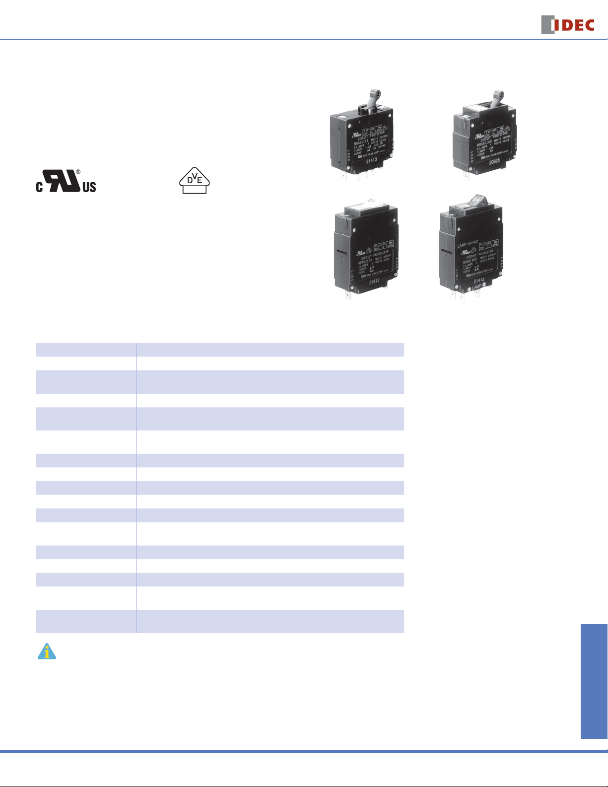
NRA Series
NRA Series
Features:
Available in 4 different styles
•
Excellent overload and short circuit protection
•
Small size and high-effi ciency
•
Life expectancy of over 10,000 operations
•
UL1077 recognized “Supplementary Protectors”
•
VDE certifi ed to EN60934
•
File No. E68029
License #116381
NRAS
NRAR
Specifi cations
Protection Method Electromagnetic tripping
Internal Circuit Series current trip
Number of Poles
Rated Voltage 250V AC, 50/60Hz, 65V DC
Rated Tripping Currents
Rated Interrupting Capacity
Auxiliary Contact SPDT microswitch: 250V AC, 5A (resistive load), 50V DC, 1A (resistive load)
Alarm Contact SPDT microswitch: 250V AC, 5A (resistive load), 50V DC, 1A (resistive load)
Reference Temperature 25°C
Operating Temperature –40 to +85°C (avoid freezing)
Insulation Resistance 100MΩ (measured with 500V megger)
Dielectric Strength
Vibration Resistance 100N (approximately 10G) (10 to 100Hz)
Shock Resistance 1,000N (approximately 100G)
Life Expectancy Minimum 10,000 cycles (at 6 operations per minute)
Termination
Illumination Voltage
(NRAR illuminated units)
NRAS and NRAN: 1, 2, 3
NRAR: 1
0.3A, 0.5A, 0.75A
1A, 2A, 3A, 5A, 7.5A, 10A, 15A, 20A, 25A, 30A
250V AC, 50/60Hz, 1,000A
65V DC, 1,000A
Between main circuit terminals: 2,000V AC, 1 minute
Between main circuit and auxiliary contact: 2,000V AC, 1 minute
Main terminal: Quick-connect receptacle 0.250” (accepts M3.5 screw terminal adapter)
Auxiliary contact, alarm contact: Quick-connect receptacle 0.080”
Neon: 120, 240V AC, 50/60Hz
Switches & Pilot Lights Display Lights Relays & Sockets Timers Terminal Blocks
NRAN
Rocker Illuminated Rocker
(with Neon lamp)
Not suitable for branch circuit protection.
Circuit Breakers
883

NRA Series
Part Numbering Guide
NRA series part numbers are composed of up to 8 part number codes. When ordering an NRA series part, select one code from each category.
Example: NRAR 1 1 11 -F - 30A -AA -1
NRAR 1 1 11 — F — 30A — AA — 1
Switches & Pilot LightsDisplay LightsRelays & SocketsTimersTerminal Blocks
j Model k Poles l Internal
Circuit
Part Number Codes: NRA Series
Description Part Number Code Remarks
Lever (round cutout) NRAS
j Model
k No. of Poles
l Internal Circuit
m Auxiliary and
Alarm Contacts
n Inertia Delay
o Rated Current
p Time Delay Curve
q Pilot Light*
Lever (rectangular cutout) NRAN
Rocker NRAR
1-pole 1 NRAR available in 1-pole only.
2-pole 2
3-pole 3
Series current trip 1
Without 00
With auxiliary contact 11 Auxiliary contact switches change state with lever and/or overload condition
With alarm contact 21 Alarm contact switches change state only with overload condition
Without inertia delay Blank
With inertia delay F
Rated current (current trip)
AC curves AA, BA,MA
DC curves AD, MD
With neon light 120V AC (50/60Hz) 1
With neon light 240V AC (50/60Hz) 2
m Auxiliary and
n Inertia Delay o Rated Current p Time Delay Curve q Pilot Light*
Alarm Contacts
0.3A, 0.5A, 0.75A, 1A, 2A, 3A, 5A,
7.5A, 10A, 15A, 20A, 25A, 30A
All multi-pole circuit breakers are simultaneous
throw/simultaneous break.
All levers are mechanically interlocked.
All current ratings must be listed in amps (A).
Example conversion: 300mA = 0.30A.
For time delay curves, see page 888.
*Applicable to illuminated NRAR only.
Circuit Breakers
1. For NRA series accessories, see page 886.
2. For NRA series time delay curves, see page 888.
3. For NRA series dimensions, see page 890.
4. Not suitable for branch circuit protection.
5. UL recognized, applicable standard: UL1077, “Supplementary Protectors.”
Circuit Breakers
884
Circuit Breakers
NRA Series
Information About Circuit Breakers
Time Delay Curve Descriptions
Time Delay Curve NRA Application
AD, AA Common curves used in molded-case circuit breakers.
BA
MD, MA Suited for motor loads that draw high inrush currents lasting a considerable length of time.
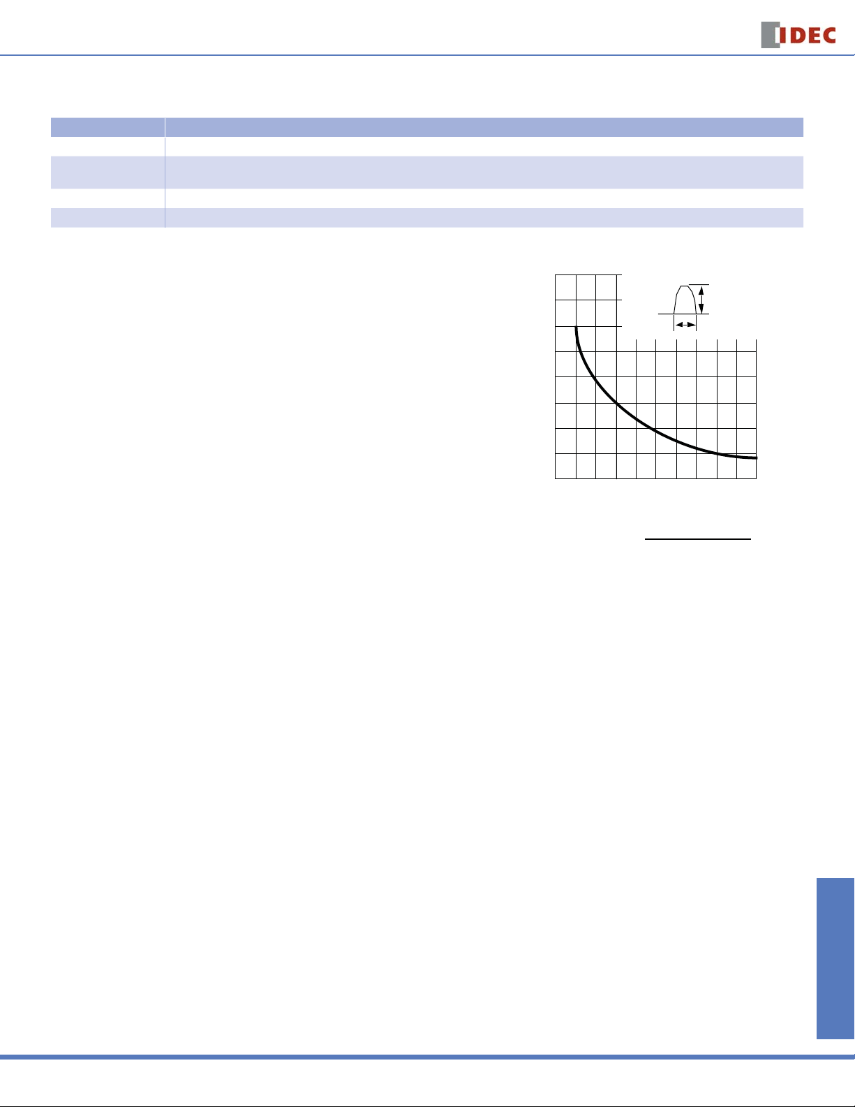
With Inertia Delay (F) Designed not to trip on 20 times the rated current (peak value) for a duration of 8ms. Suited for transformer and lamp loads that draw steep inrush currents.
Inertia Delay Description
Circuit breakers equipped with inertia delay do not respond to high inrush currents such as
those produced by transformer, lamp, or motor loads, but perform specifi ed interruption on
rated overcurrents.
Specify inertia delay by inserting an “F” in the part number as shown in Part Number Guide on
previous page.
Response to overcurrent is quite fast. Suited for protection of semiconductor circuits with very little overload tolerance. If overcurrents are expected to
fl ow, fuses may be required according to the circuit characteristics.
16,000
14,000
12,000
10,000
8,000
6,000
Percent of Rated Current
4,000
2,000
12 34 567 8910
Pulse
Width
Pulse Width (ms)
Pulse Peak
Current
(duration)
Switches & Pilot Lights Display Lights Relays & Sockets Timers Terminal Blocks
1. P
ercent of Rated Current =
2. Based on sinusoidal or parabolic pulse profi le.
Notes
Multi-Pole
Multi-pole types such as 2- or 3-pole should be assembled by IDEC.
Because of their characteristics, 1-pole breakers cannot be combined to provide multi-pole units.
Auxiliary and Alarm Contacts
Multi-pole units can incorporate auxiliary and alarm contacts.
Auxiliary and alarm contacts will not work with IDEC’s DIN rail adapters.
Pulse Peak Current
Protector Rated Current
x 100%
Circuit Breakers
885
 Loading...