

Page 1
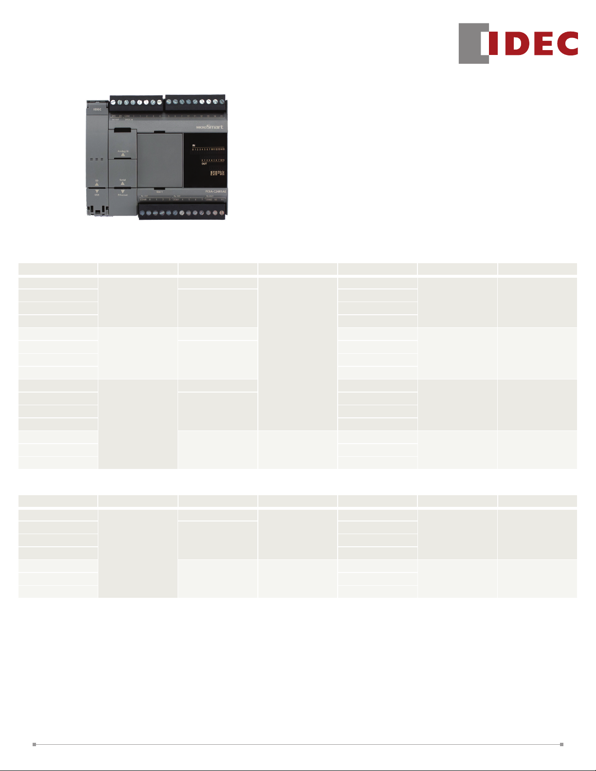
MicroSmart FC6A PLC
CPU Module Specifications
KEY F E AT U RES
• Embedded Ethernet port
• Embedded SD memory port
• Modbus TCP and RTU
• Embedded RS232C/RS485 user selectable
• Maximum 520 digital I/O
• Maximum 126 analog I/O
• Data Logging
• Web Server Functions
• Large programming and data memory
• CAN J1939 CPU
• Built-in Web Page Editor for user webpage
Standard Base Module
Part Number Tot al I/O Power Voltage Input Voltage Output Type Maximum Digital I/O Maximum Analog I/O
FC6A-C16R1A E
FC 6A -C16R1CE
FC 6A -C16P 1CE Transistor Source
FC6A-C16K1CE Transistor Sink
FC6A-C24R1AE
FC6A-C24R1CE
FC6A-C24P1CE Transistor Source
FC 6A -C24K1CE Transistor Sink
FC6A-C40R1AE
FC6A-C40R1CE
FC6A-C40P1CE Transistor Source
FC6A-C40K1CE Transistor Sink
FC6A-C40R1DE
FC6A-C40P1DE Transistor Source
FC6A-C40K1DE Transistor Sink
16
(9 inputs, 7 outputs)
24
(14 inputs, 10 outputs)
40
(24 input s, 16 outputs)
100 -24 0V AC
24V DC
100 -24 0V AC Relay
24V DC
24V DC
100 -24 0V AC Relay
24V DC
12V D C
Sink/Source
12V DC
Sink/Source
Relay
Relay
Relay
Relay
Relay
400 100
504 124
520 126
40 6
CAN J1939 Base Module
Part Number Tot al I/O Power Voltage Input Voltage Output Type Maximum Digital I/O Maximum Analog I/O
FC6A-C40R1AEJ
FC6A-C40R1CEJ
FC6A-C40P1CEJ Transistor Source
FC6A-C40K1CEJ Transistor Sink
FC6A-C40R1DEJ
FC6A-C40P1DEJ Transistor Source
FC6A-C40K1DEJ Transistor Sink
40
(24 input s, 16 outputs)
100 -24 0V AC
24V DC
12V D C
24V DC
Sink/Source
12V DC
Sink/Source
Relay
Relay
Relay
520 126
40 6
1
Page 2

SPECIFICATIONS
FC6A-C40R1AE
FC6A-C 40R1C E
FC6A-C40P1CE
FC6A-C 40K1CE
FC 6A -C 40R1DE
FC6A-C40P1DE
Part Number
FC6A-C16R1AE
FC6A-C16R1C E
FC6A-C16P1CE
FC6A-C16K1CE
FC6A-C24R1AE
FC6A-C24R1CE
FC6A-C24P1CE
FC6A-C24K1CE
FC 6A -C 40K1DE
Rated Power Voltage AC: 10 0 to 240 V AC, DC: 24V DC , 12V DC
Allowable Voltage Range AC: 8 5 to 264 V AC 24V DC: 20.4 to 28 .8V DC (including ripple), 12V DC: 10.2 to 18.0V
Rated Frequency AC: 5 0/60Hz ( 47 to 63 Hz)
FC6A-C16R1AE: 100 -240V AC, 3 3VA
AC
Maximum
Power
Consumption
(CPU m odule)
DC
Allowable Momentary
Power Interruption
Dielectr ic Strength
Insulation Resistance
Noise Resistance
FC6A-C24R1A E: 100 -240V AC, 3 5VA
FC6A-C 40R1AE : 100 -240V AC, 41VA
FC6A-C 40R1AE J: 100 -240V AC, 3 7VA
FC 6A-C16R1C E: 24V DC 140 mA, 3.36 W
FC6A-C24R1CE:
FC 6A-C 40R1C E:
FC 6A-C16P1CE:
FC6A-C24P1CE:
FC 6A-C 40P1C E:
24V DC 155m A, 3.72W
24V DC 195 mA, 4.68 W
24V DC 190mA, 4.6W
24V DC 20 0mA, 4.8 W
24V D C 205 mA, 5.0W
Bet ween power and ground terminals: 1,5 00V AC, 1 minute
Bet ween I/O and ground terminals: 1,5 00V AC, 1 minute
Bet ween power and ground terminals: 100 M minimum (5 00V DC megger)
Bet ween I/O and ground terminals: 100 M Ω minimum (5 00V DC megger)
AC or DC power t erminal: 1.5k V (DC type: 1kV ), 5 0 ns to 1 s
I/O terminals (coupling clamp): 1.5kV, 5 0ns to 1s coupling adapt er
FC6A- C16K1CE:
FC 6A-C 24K1CE:
FC6A-C40K1CE:
FC 6A-C 40R1DE:
FC 6A-C 40P 1DE:
FC6A-C40K1DE:
24V DC 19 0mA, 4.6 W
24V DC 20 0mA, 4.8 W
24V DC 205mA, 5 .0W
12V DC 34 5mA, 4.14W
12V DC 260m A, 3.12W
12V DC 26 0mA, 3.12W
10 ms (at rated voltage)
FC 6A-C 40R1C EJ:
FC 6A-C 40P1C EJ:
FC 6A-C 40K1CE J:
FC 6A-C 40R1DE J:
FC 6A-C 40P 1DEJ:
FC 6A-C 40K1D EJ :
24V DC 20 5mA, 5.0W
24V DC 175mA , 4.2W
24V DC 175 mA, 4.2W
12V DC 340mA , 4.08W
12V DC 32 0mA , 3.9W
12V DC 320mA , 3.9W
AC: 40A ma ximum
Inrush Current
24V DC: 3 5A maximum
12V DC : 35A ma ximum
Power Supply Wire AWG22, AWG18
Operating Temperature -10 to +5 5°C (no freezing)
Storage Temperature -25 to + 70°C (no f reezing)
Relative Humidity Level RH1 (IEC 61131-2-10 to 95% (no condensation)
Altitude Opera tion: 0 to 2 ,0 00m, 7 95 t o 1,0 13hPa, Transp ort: 0 to 3, 00 0m, 701 to 1,013hPa
Pollution Degree 2 (IEC 6 066 4-1)
Corrosion Immunity Free f rom corrosive gases
Degree of Protection IP20 (IEC 605 29)
Ground D-type ground (Class 3 ground)
Grounding Wire AWG16
Vibration Resistance
5 to 8. 4 Hz amplit ude 3 .5 mm, 8. 4 to 150 Hz accelera tion 9.8 m/s² (1G),
2 hours per ax is on each of thr ee mutually perpendicular axes (IEC 6 1131-2 )
Shock Resis tance 147 m/s² (15G), 11 ms dura tion, 3 shocks per axis on three mu tually per pendicular axes
Mounting DIN rail or panel moun ting
Weight
AC: 3 50g
DC: 3 40g
AC: 4 20 g
DC: 4 00g
AC: 5 60g
DC (relay): 53 0g
DC (transist or) : 48 0g
FC6A-C40R1AEJ
FC6A-C 40R1C EJ
FC6A-C40P1CEJ
FC6A-C 40K1CEJ
FC 6A -C 40R1DEJ
FC6A-C40P1DEJ
FC 6A -C 40K1DE J
AC: 5 60g
DC (relay/ 24V DC) : 53 0g
DC (relay/12V DC): 56 0g
DC (transist or/ 24V DC): 48 0g
DC (transist or/12V DC): 530g
2
Page 3

SPECIFICATIONS CONT.
FC6A-C40R1AE
FC6A-C16R1AE
Part Number
Control System Stored program system
Instruction Words
Program Capacit y 1 38 4KB (4 8,00 0 steps)/72KB (9,00 0 steps)
User Program St orage Serial Flash Memory (100,00 0 times rewri table)
Processing Time
I/O Points
Expandable Modules 4 modules 7 modules
Expandable I/O Point s with E xpansion
Modules
Expandable Modules w ith Expansion
Interface Modules
Expandable I/O Point s with E xpansion
Interface Modules
Internal Relay 12 ,4 00 points
Special Internal Relay 256 points
Shift Register 256 points
Data Register 54,000 points
Special Data Register 500 points
Counter 512 points
Timer (1ms, 10ms , 100ms , 1s) 1,024 points
Clock Clock accuracy: ±30 sec/month (t ypical) at 2 5°C
RA M
Backup
Self-diagnostic Function
Input Filter 0 ms (without filt er), 3 to 15ms (selectable in i ncrement s of 1ms)
Catch Input/ Interrupt Input
Highspeed
Counter
Analog
Potentiometer
Analog Voltage
Input
Pulse
Output
Ex ternal Pow er
Suppl y for Sensor
(AC only)
USB Port USB mini-B (maintenance communication)
Serial Por t 1, CAN Por t RS 232C or RS 485
Ethernet Por t 1 Ethernet (maintenance communication, user communication, user communication, Modbus TCP server/client)
SD Card Slot Embedded
Cartridge (option) One cartridge can be added Two cartridges can be added
HMI Module (option) Yes Yes Yes Yes
Note: T he maximum number of r elay ou tputs that can be turned on simultaneously is limited.
Note 1: 1 step equals 8 b ytes.
Note 2: W hen 72KB is selected, download function can b e used during RUN.
Note 3: Not including expansion I/O service time, counter timer processing time, data link processing time, and interrupt processing time.
Note 4: Maintenance communication, user communication, dat a link, Modbus R TU master/slave communication.
Basic 42
Advanced 124
Basic Instruction 42us/1,000 steps
END Proces sing
Input 9 points 14 points 24 points
Output 7 points 10 points 16 points
Backup Data Internal relay, shi ft regis ter, counter, data regis ter, timer, special data register, special internal relay
Batter y Lithium pri mar y bat tery (BR2 032)
Bat tery Li fe Appr ox. 4 years
Replaceability Possible
Maximum Counting Frequency
and High-speed Counter Points
Counting Range 0 to 4, 294,9 67,29 5 (3 2 bits)
Operation Mode Rotary encoder mode, adding coun ter mode, frequency measuremen t mode
Quanti ty 1 point −
Data R ange 0 to 1,00 0 −
Quanti ty 1 point −
Input Volt age Range 0 to 10V −
Input Impedance Approx. 100K −
Digital Resolution Approx. 1, 00 0 steps (10 bits) −
Quanti ty 4 points
Maximum Frequency
Output Voltage/
Current
Overload
Detection
Isola tion from t he
internal circui t
3
FC6A-C16R1C E
FC6A-C16P1CE
FC6A-C16K1CE
128 points 224 points
Keep data, user program sum check (EE PROM), user program sum check (R AM), timer/count er preset value sum check ,
user pr ogram synta x check, user progr am execution check, W DT check, user program wri te check, po wer failur e, clock error,
data ink connect ion check, I /O bus initialization check
Six input s I0, I1, I6, I 7 Minimum turn on pulse w idth: 5 s max .
Minimum turn of f pulse width: 5s max .
Total 6 point s Single/ two-phase selectable: 100 kHz (single-phase: 4 points, two-phase: 2 points)
Single-p hase: 5 kHz ( 2 points)
High speed ou tpu t port: 100 kHz (2 points) ma ximum
Middle speed output port: 5 kHz (2 points ma ximum)
FC6A-C24R1AE
FC6A-C24R1CE
FC6A-C24P1CE
FC6A-C24K1CE
1ms maximum
8 modules
256 points
24V (+10%, -15%) / 250 mA
Impossible
Transformer-isolated
4
FC6A-C 40R1C E
FC6A-C40P1CE
FC6A-C 40K1CE
FC 6A -C 40R1DE
FC6A-C40P1DE
FC 6A -C 40K1DE
2
I3, I 4 Minimum turn on pulse w idth: 35s max.
Minimum turn of f pulse width: 35 s max.
FC6A-C40R1AEJ
FC6A-C 40R1C EJ
FC6A-C40P1CEJ
FC6A-C 40K1CEJ
FC 6A -C 40R1DEJ
FC6A-C40P1DEJ
FC 6A -C 40K1DE J
640KB (80,000)
72KB (9 ,000 steps)
High speed output port:
100 k Hz maximum
CAN J1939
2
3
Page 4

USB Port Specifications
FC6A-C40R1AE
FC6A-C16R1AE
Part Number
USB Ty pe USB mini-B
USB Standard USB 2 .0 full speed
Isolation Not isolated from the internal circuit
Communication
Function
FC6A-C16R1C E
FC6A-C16P1CE
FC6A-C16K1CE
FC6A-C24R1AE
FC6A-C24R1CE
FC6A-C24P1CE
FC6A-C24K1CE
Maintenance communication to PC
FC6A-C 40R1C E
FC6A-C40P1CE
FC6A-C 40K1CE
FC 6A -C 40R1DE
FC6A-C40P1DE
FC 6A -C 40K1DE
Ethernet Port 1 Specifications
FC6A-C40R1AE
FC6A-C16R1AE
Part Number
Communication
Type
Data Tra nsfer 10 BASE -T, 100 BASE -TX
Connector RJ45
Cable CAT.5STP
Maximum C able
Length
Isolation Pulse trans isolation
Communication
Function
FC6A-C16R1C E
FC6A-C16P1CE
FC6A-C16K1CE
Maintenance communication ser ver, user communication ser ver,
FC6A-C24R1AE
FC6A-C24R1CE
FC6A-C24P1CE
FC6A-C24K1CE
Modbus TCP (ser ver/clien t), PING, SN TP
FC6A-C 40R1C E
FC6A-C40P1CE
FC6A-C 40K1CE
FC 6A -C 40R1DE
FC6A-C40P1DE
FC 6A -C 40K1DE
IEEE802.3 compliant
100m
FC6A-C40R1AEJ
FC6A-C 40R1C EJ
FC6A-C40P1CEJ
FC6A-C 40K1CEJ
FC 6A -C 40R1DEJ
FC6A-C40P1DEJ
FC 6A -C 40K1DE J
FC6A-C40R1AEJ
FC6A-C 40R1C EJ
FC6A-C40P1CEJ
FC6A-C 40K1CEJ
FC 6A -C 40R1DEJ
FC6A-C40P1DEJ
FC 6A -C 40K1DE J
Serial Port 1, CAN Port Specifications
FC6A-C40R1AE
FC6A-C16R1AE
Part Number
Port Type Serial port 1 CAN por t
Communication
Type
Connector RJ45
Cable CAT. 5S TP
Maximum Baud
Rate Maximum
Cable Leng th
Isolation Not isolated from the internal circuit
Communication
Function
FC6A-C16R1C E
FC6A-C16P1CE
FC6A-C16K1CE
115, 200 bps
RS2 32C: 5 m, RS4 85 : 200m
Maintenance communication, user communication,
Modbus RTU (master/slave)
FC6A-C24R1AE
FC6A-C24R1CE
FC6A-C24P1CE
FC6A-C24K1CE
RS2 32C or RS4 85 selectable CAN
FC6A-C 40R1C E
FC6A-C40P1CE
FC6A-C 40K1CE
FC 6A -C 40R1DE
FC6A-C40P1DE
FC 6A -C 40K1DE
FC6A-C40R1AEJ
FC6A-C 40R1C EJ
FC6A-C40P1CEJ
FC6A-C 40K1CEJ
FC 6A -C 40R1DEJ
FC6A-C40P1DEJ
FC 6A -C 40K1DE J
Terminal Block
(5-pole)
SAE J1939 -11/SAE
J19 39-15
SAE J1939 -11:
25 0bps: 4 0m, stubs,
1m maximum
SAE J1939 -15:
25 0bps: 4 0m, stubs,
3m maximum
Isola ted from the
internal circui t
J1939
CAN J1939 Specifications
FC6A-C40P1CEJ
Part Number
SAE J1939 -11: Physical Layer, 2 50 K bits/s, Twisted Shielded Pair
SAE J1939 -15: Reduced Physical Layer, 2 50 K bits/s, Unshielded Twisted Pair
Support ed SAE J19 39
Maximum No. of Send Message 100
Trans mit /Re ceiv e
Message
Transmission
Function
Receive Function
Request Function Yes
Network Management Function Static address/dynamic address management
PGNs used Internally
Note 1: Message is t ransmitted in END proc essing. Actual tr ansmission cycle is af fected by the ladder execution c ycle.
Note 2: Receive message is transferr ed from internal bu ffer to dat a register in END processing.
Maximum No. of Receive Message 200
Transmittable PGN Optional
Maximum L ength of
Transmit/Receive Message
Transmission Type Event transmission/periodical transmission
Even t
Transmission
Cycle
Transmission
Receive Method Polling reception
Receive Cycle Monitor 0, 10 to 6 55,35 0 ms (disabled at 0)
NAME Optional (automat ic sw itching o f st atic address /d ynamic address management at highest-or der bit)
Number of Nodes Manageable 128 nodes
Transmission Method Internal relay
Transmission Method Internal relay
Transmission Cycle
SAE J1939 -21: Data Link Layer
SAE J1939 -71: Vehicle Applica tion Layer
SAE J1939 -73: Application L ayer - Diagnostics
SAE J1939 -75: Applicat ion Layer - Genera tor Sets and Industrial
SAE J1939 -81: Net work Management
1
FC6A-C 40K1CEJ
FC6A-C40P1DEJ
FC 6A -C 40K1DE J
1 to 252 by tes/message
10 to 655,3 50 ms (in increments of 10ms)
00EA 00h: Reques t PGN
00E800h: Acknowledgement
00EB00h: TP.DT
00EC00h: TP.CM
00EE 00 h: Address claim
2
FC6A-C40R1AEJ
FC6A-C 40R1C EJ
FC 6A -C 40R1DEJ
4
Page 5

Input Specifications
FC6A-C40R1AE
FC6A-C16R1AE
Part Number
Input Points 9 (9/ 1 common) 14 (14/1 common) 24 (2 4/ 1 common)
Rated Input Voltage
Input Volt age Range
Rated Input Current
Input Impedance
Turn ON Time
Turn OF F Time
Isolation
Input Type Type1 (IEC 61131-2)
Ex ternal Load for I /O
Interconnection
Signal Determination Method Static
Effect of Improper Inpu t
Connection
Cable Leng th 3m in compliance wi th electromagnetic immunity
Insertion Durability 100 times minimum
Connector
Applicable Ferrule
FC6A-C16R1C E
FC6A-C16P1CE
FC6A-C16K1CE
AC, 24V DC : 24V DC sink/source inpu t signal
12V DC : 12V DC sink /source input signal
AC, 24V DC : 0 to 28.8V DC
12V DC : 0 to 18.0V DC
AC, 24V DC: high speed input port: 5mA /pt, middle/normal speed input port 7mA/pt
12V DC: high speed input port: 5mA /pt, middle/normal speed input port 6mA/pt
AC, 24V DC: high speed input port: 4.9k, middle/normal speed input port: 3.4k
12V DC: high speed input port: 1.8k , middle/normal speed input port: 2.0k
High-speed input port: 5s + filter value
Middle-speed input port: 35s + filter value
Normal-speed input port: 35s + filter value
High-speed input port: 5us + filter value
Middle-speed input port: 35us + filter value
Normal-speed input port: 100us + filter value
Bet ween input t erminals: Not isolated
Internal circuit: Photocoupler-isolated
Both sink ing and sourcing input signals can be connect ed, t herefor e reverse connec tion does not cause damage.
If any input exceeding the rated value is applied , permanen t damage may be caused.
FC6A-C24R1AE
FC6A-C24R1CE
FC6A-C24P1CE
FC6A-C24K1CE
Not needed
1-wire: A I 0. 5- 8 WH (Phoen ix Contact)
2-wire: AI-T WIN 2× 0.5- 8 WH (Phoenix Contact)
FC6A-C 40R1C E
FC6A-C40P1CE
FC6A-C 40K1CE
FC 6A -C 40R1DE
FC6A-C40P1DE
FC 6A -C 40K1DE
FC6A-C40R1AEJ
FC6A-C 40R1C EJ
FC6A-C40P1CEJ
FC6A-C 40K1CEJ
FC 6A -C 40R1DEJ
FC6A-C40P1DEJ
FC 6A -C 40K1DE J
Transistor Output Specifications
Part Number
Transistor Output Points 7 (7/1 common) 10 (10/1 common) 16 (8/ 1 common)
Output Type
Rated Load Voltage 24V DC: 24V DC 12 V DC: 12V DC
Voltage Tolerance 24V DC: 19 .2 to 28 .8V DC 12V DC: 10.2 to 18.0V DC 24V D C: 19 .2 to 28 .8V DC 12V DC: 10.2 to 16.0V DC
Rated Load
Current
Volt age Drop (ON Voltage) 1V max (voltage between C OM and output terminal when out put is on.)
Inrush Current 1A
Leakage Cur rent 0.1m A maximum
Clamping Voltage 24V DC: 3 9V ±1V 12V DC: 27 V ±1V
Maximum L amp Load 12W
Inductive Load
Overcurrent Protection Transis tor Sink Ou tpu t: No Transis tor Source Output : Overcurrent is det ected by current limi t resistance.
Ex ternal Cur ren t Draw
Isolation Be tw een ou tput terminal and Internal circuit : Photocoupler-isolated Bet ween output terminals : Not isolated
Connector
Output Delay
Note 1: This overcurrent signals consist of one signal per 4 point outputs. When microprocessor gets this overcurrent signal by interrupt input, microprocessor turns off 4pt outputs of this
category at fixed time (approx. 1 second).
Transis tor Sink FC6A-C16K1CE/FC6A-C24K1CE/FC6A-C40K1CE/FC6A-C40K1DE/FC6A-C40K1CEJ/FC6A-C40K1DEJ
Transistor Source FC6A-C16P1CE/FC6A-C24P1CE/FC6A-C40P1CE/FC6A-C40P1DE/FC6A-C40P1CEJ/ FC6A-C40P1DEJ
Per Point 0.5A
Per Common 3.5A 5A 4A
Insertion
Durability
Applicable Ferrule 1-wire: A I 0. 5- 8 WH (Phoen ix Contact) 2-w ire: AI-T WIN 2× 0.5-8 WH (Phoenix Cont act)
Turn ON Time
Turn OF F Time
FC6A-C16P1CE
FC6A-C16K1CE
High speed input port: 5s Middle speed input port: 30s
Normal speed input port: 30 0s
High speed input port: 5s Middle speed input port: 30s
Normal speed input port: 30 0s
FC6A-C24P1CE
FC6A-C24K1CE
24V DC: L /R=10ms (2 8.8V DC, 1Hz) 12V DC : FC6A-C 40P1DE/ FC6A-C 40K1DE , L/R =10ms (18.0V DC 1Hz),
FC6A-C 40P1DEJ/F C6A-C4 0K1DEJ, L /R=10 ms (16.0V DC, 1Hz)
24V DC: 10 0mA max imum, 24 V DC (power volt age at t he +V terminal, -V t erminal at source)
12V DC : 100mA maximum, 12V DC (power vol tage at the +V terminal, -V ter minal at source)
FC6A-C40P1CE
FC6A-C 40K1CE
FC6A-C40P1DE
FC 6A -C 40K1DE
100 times minimum
FC6A-C40P1CEJ
FC6A-C 40K1CEJ
FC6A-C40P1DEJ
FC 6A -C 40K1DE J
1
High speed input port: 5s
Middle speed input port: 300s
High speed input port: 5s
Middle speed input port: 300s
5
Page 6

Relay Output Specifications
Part Number
FC6A-C16R1AE
FC6A-C16R1C E
FC6A-C24R1AE
FC6A-C24R1CE
Relay Output Point s 7 10 16
COM1 4 4 4
Output Points
per Common
Line
COM2 3 4 4
COM3 — 2 4
COM4 — — 4
Output Type 1NO
Maximum
Load Current
Per Point 2A
Per Common
COM 1: 7A
COM2: 6 A
COM1: 7A C OM3: 4 A
COM 2: 7A
COM1: 7A C OM3: 7A
COM2: 7A COM4 : 7A
Minimum Switching Load 1mA /5V DC (reference value)
Initial Contact Resistance 30 mΩ maximum
Electrical Life 100,0 00 operations minimum (rated load 1,800 operations/hour)
Mechanical Life 20,0 00,000 operations minimum (no load 18,00 0 operations/hour)
Rated Load Resist ive load: 24 0V AC 2A, 3 0V DC 2A Inductive load: 24 0V AC 2A (cos ø = 0. 4), 30V D C 2A (L /R =7 ms)
Bet ween output and ground terminals: 1, 500V AC, 1 minut e
Dielectric Strength
Bet ween output terminal and internal circui t: 1, 500V AC, 1 minute
Bet ween output terminals (C OMs): 1,50 0V AC, 1 minute
Connector
Insertion/ Removal
Durability
100 times minimum
Applicable Ferrule 1- wire: AI 0 .5-8 W H (Phoeni x Con tact) 2-wire: AI -TWIN 2 ×0.5 -8 WH (Phoeni x Con tact)
FC6A-C40R1AE
FC6A-C 40R1C E
FC 6A -C 40R1DE
DIMENSIONS (all dimensions are in mm)
FC6A-C40R1AEJ
FC6A-C 40R1C EJ
FC 6A -C 40R1DEJ
FC6A-C16R1AE /FC6A-C16R1CE
FC6A-C16P 1CE /FC 6A-C16K1CE
95.0
2.9
90.0
13.6
2.9
FC6A-C40R1AE/FC6A-C40R1CE
FC6A-C40P1CE/FC6A-C40K1CE
FC6A-C40R1DE/FC6A-C40P1DE
FC 6A- C40 K1DE
163.0
FC6A-C24R1AE/FC6A-C24R1CE
FC6A-C24P1CE/FC6A-C24K1CE
130.9
114.3
73.02.7
45.4
4.0
15.4
110.0
2. 9
90.0
2. 9
13.6
2. 7
73.0
130.9
114.3
45.4
4.0
15.4
FC6A-C40R1AEJ/FC6A-C40R1CEJ
FC6A-C40P1CEJ/FC6A-C40K1CEJ
FC6A-C40R1DEJ/FC6A-C40P1DEJ
45.4
4.0
15.4
FC 6A- C40 K1DEJ
163.0
130.9
114.3
11.3
73.0
2.9
2.7
90.0
13.6
2.9
45.4
4.0
15.4
130.9
114.3
73. 0
2. 7
2. 9
90.0
13.6
2. 9
6
Page 7

Temperature derating curves: Input voltage vs. I/O Simultaneous ON Ratio (%)
Input (with car tridge) Output (with cartridge) Input (w/o cartridge) Output (w/o car tridge)
FC6A- C16K1CE
FC 6A-C 24K1CE
FC 6A-C 40K1CE
FC 6A-C 40K1D E
FC 6A-C 40K1CE J
FC 6A-C 40K1D EJ
FC6A- C16K1CE
FC 6A-C 24K1CE
FC 6A-C 40K1CE
FC 6A-C 40K1D E
FC 6A-C 40K1CE J
FC 6A-C 40K1D EJ
FC6A-C24P1CE
FC 6A-C 40P1C E
FC 6A-C 40P 1DE
FC 6A-C 40P1C EJ
FC 6A-C 40P 1DEJ
FC6A-C24P1CE
FC 6A-C 40P1C E
FC 6A-C 40P 1DE
FC 6A-C 40P1C EJ
FC 6A-C 40P 1DEJ
Input Voltage (V DC)
28.8V
24.0V
0V
0%
I/O Simultaneous ON Ration (%)
Ambient Temperature
45 ºC
Ambient Temperature
55 ºC
100%
70% 80%
Input Voltage (V DC)
28.8V
24.0V
0V
0%
I/O Simultaneous ON Ration (%)
Input (with car tridge) Output (with car tridge)
FC6A-C24P1CE
FC 6A-C 40P1C E
FC 6A-C 40P 1DE
Input Voltage (V DC)
28.8V
24.0V
0V
0%
I/O Simultaneous ON Ration (%)
FC 6A-C 40P1C EJ
FC 6A-C 40P 1DEJ
Ambient Temperature
45 ºC
Ambient
Temperature
55 ºC
100%40% 50%
FC6A-C24P1CE
FC 6A-C 40P1C E
FC 6A-C 40P 1DE
Input Voltage (V DC)
28.8V
24.0V
0V
0%
I/O Simultaneous ON Ration (%)
FC 6A-C 40P1C EJ
FC 6A-C 40P 1DEJ
Ambient Temperature
Ambient
Temperature
55 ºC
Output Internal Circuit
100V to 240V AC, 24V DC
Transistor Sink Output
Internal
Circuit
V (+)
Output
12V D C
Transistor Sink Output
Internal
Circuit
45 ºC
100%40% 50%
Ambient Temperature
45 ºC
Ambient Temperature
55 ºC
100%
70% 80%
Input Internal Circuit
100V to 240V AC, 24V DC
Transistor Sink Output
I0, I1, I6, I7
Input
COM
I2 to I5, I10 to I27
Input
COM
V (+)
Output
Input Voltage (V DC) Ambient Temperature
28.8V
24.0V
0V
0%
I/O Simultaneous ON Ration (%)
100V to 240V AC, 24V DC
Transistor Source Output
Internal
Circuit
45 ºC
Ambient
Temperature
55 ºC
100%60% 80%
12V D C
Transistor Sink Output
I0, I1, I6, I7
Input
COM
Internal CircuitInternal Circuit
I2 to I5, I10 to I27
Input
COM
V (+)
Output
Input Voltage (V DC)
28.8V
24.0V
0V
0%
I/O Simultaneous ON Ration (%)
Ambient Temperature
12V D C
Transistor Source Output
Internal
Circuit
45 ºC
100%60% 80%
Ambient
Temperature
55 ºC
V (+)
Output
Internal CircuitInternal Circuit
COM( –)
COM( –)
COM( –)
COM( –)
7
 Loading...