

Page 1

FC4A SERIES
MICROSmart
Web Server Unit
Instruction Manual
FC9Y-B919
Phone: 800.894.0412 - Fax: 888.723.4773 - Web: www.clrwtr.com - Email: info@clrwtr.com
Page 2
PRECAUTIONS
● Read this user’s manual to make sure of correct operation before starting installation, wiring, operation,
maintenance, and inspection of the MicroSmart modules.
● All MicroSmart modules are manufactured under IDEC’s
rigorous quality control system, but users must
add a backup or failsafe provision to the control system using the MicroSmart in applications where
heavy damage or personal injury may be caused in case the MicroSmart should fail.
● In this user’s manual, safety precautions are cate g orized in order of im
portance to Warning and Caution.
Precautions on hazards that could result in death or serious injury if equipment is handled
incorrectly.
Precautions on ha
zards that could result in injury or equipment damage if equipment is handled
incorrectly.
● Turn off the po
wer to the MicroSmart before starting in
stallation, remo
val, wiring, maintenance, and
inspection of the MicroSmart. Failure to turn power off may cause electrical shocks or fire hazard.
● Special expertise is required to install, wire, program, and operate the MicroSmart. People without such
expertise must not use the
MicroSmart.
● Emergency stop and interlocking circuits must be configured outside the Mi
croSmart. If such a circuit is
configured inside the MicroSmart, failure of the MicroSmart may cause disorder of the control system,
damage, or accidents.
● Install the MicroSmart according to the instructions described in this
user’s manual. Improper installation
will r
esult in falling, failure, or malfunction of the MicroSmart.
● The MicroSmart is designed for installation in a cabinet
. Do not install the MicroSmart outside a cabinet.
● Install the MicroSmart in environments described in this user’s manual
. If the MicroSmart is used in places
where the MicroSmart is subjected to high-temperature, high-humidity, condensation, corrosive gases,
excessive vibrations, and excessi ve shocks, then electrical shocks, fire hazard, or malfunction will result.
● The environment for using the MicroSmart is “Pol
lution de
gree 2”. Use the MicroSmart in environments
of pollution degree 2 (according to IEC 60664-1).
● Prevent the MicroSmart from falling while moving or transporting
it, otherwise damage or malfunction of
the MicroSmart will result.
● Prevent metal fragments and pieces of wire from dropping inside the MicroSm
art housing. Put a cover on
the MicroSmart modules during installation and wiring. Ingress of such fragments and chips may cause
fire hazard, damage, or malfunction.
● Use a power supply of the rated value. Use of a
wrong power su
pply may cause fire hazard.
● Use an IEC 60127-approved fuse on the power line outside the MicroSmart. This is required when
equipment containing the MicroSm
art is destined for Europe.
● Use an IEC 60127-approved fuse on the output circuit. This is required when equipment containing the
MicroSmart
is destined for Europe.
● Use an EU-approved circuit breaker. This is required when equipment containing the MicroSma
rt is
destined for Europe.
● Make sure of safety before starting and stopping the MicroSmart or when operating the MicroSmart to
force
outputs on or off. Incorrect operation on the MicroSmart may cause machine damage or accidents.
● Do not connect the ground wire directly to the MicroSmart. Connect a protective ground to the cabinet
containing the MicroSmart using an M4 or la
rger screw. This is required when equipment containing the
MicroSmart is destined for Europe.
● Do not disassemble, repair, or modify the MicroSmart modules.
● Dispose of the battery in the MicroSmart module
s when the battery is dead in accordance with perta
ining
regulations. When storing or disposing of the battery, use a proper container prepared for this purpose.
This is required when equipment containing the MicroSmart is destined for Europe.
● When disposing of the MicroSmart, do s
o as an industrial waste.
WARNING
!
CAUTION
!
WARNING
!
CAUTION
!
Phone: 800.894.0412 - Fax: 888.723.4773 - Web: www.clrwtr.com - Email: info@clrwtr.com
Page 3

INTRODUCTION
Thank you for your purchase of the IDEC Izumi Web Server Unit.
This manual contains the specifications of the Web Server Unit (Mic
roSmart communication module), and
describes how to use the unit.
Before using the unit, read this manual to thoroughly familiarize yourself with t
his product's functions and
performance, and to ensure correct operation.
• WindLDR is a registered trademark of IDEC Izu
mi Corporation.
• Microsoft
®
Windows® and Microsoft® Internet Explorer are registered trademarks or trademarks of
Microsoft Corporation (US) in the US and other countries.
• Java and all the trademarks and logos related to Java are registered trademarks or trademarks of Sun
Microsystems, Inc. (US)
in the US and other countries.
• Netscape, Netscape Navigator and Netscape’s N logo are registered trademarks of Netscape
Communicati
ons Corporation in the US and other countries. Netscape’s logo, Netscape Communicator
and other product/service names are trademarks (or registered trademarks in some countries) of Netscape
Communications Corporation. Copyrights of Netscape Navigator are reserved by Netscape
Communications Corporation.
• Ethernet is a trademark of X
erox Corpor
ation USA.
• Other company names and product names shown in this manual are trademarks or registered tradem
arks
of each company.
Important
1. Unauthorized reproduction, reprinting, sale, transfer or lending of this manual in whole or part is strictly
prohibited.
2. The contents of this manual are subject to change without prior notice.
3. Every effort has been taken to ensure the accuracy of the information contained in this manual.
However, if you do discover an error or omission, report it to your place of purchase or nearest IDEC
Izumi sales office or branch.
Phone: 800.894.0412 - Fax: 888.723.4773 - Web: www.clrwtr.com - Email: info@clrwtr.com
Page 4

REVISION HISTORY
The revision history of this manual (FC9Y-B919) is shown below.
Date of revision Documentation control No. Description
June 2005 B919-(0) First edition
This manual’s documentation control No. is printed at the back cover.
Phone: 800.894.0412 - Fax: 888.723.4773 - Web: www.clrwtr.com - Email: info@clrwtr.com
Page 5

TABLE OF CONTENTS
Precautions
Introduction
Revision History
Table of Contents
CHAPTER 1: Overview . . . . . . . . . . . . . . . . . . . . . . . . . . . . . . . . . . . . . . . 1-1
1 Web Server Unit Overview . . . . . . . . . . . . . . . . . . . . . . . . . . . . . . . . . . 1-2
CHAPTER 2: Specifications. . . . . . . . . . . . . . . . . . . . . . . . . . . . . . . . . . . 2-1
1 Names and Specifications of Module Components . . . . . . . . . . . . . . . 2-2
2 Performance Specifications . . . . . . . . . . . . . . . . . . . . . . . . . . . . . . . . . 2-3
CHAPTER 3: Module Operation. . . . . . . . . . . . . . . . . . . . . . . . . . . . . . . . 3-1
1 Web Server Unit Settings . . . . . . . . . . . . . . . . . . . . . . . . . . . . . . . . . . . 3-2
2 Remote Maintenance Function. . . . . . . . . . . . . . . . . . . . . . . . . . . . . . 3-10
3 Web Server Function . . . . . . . . . . . . . . . . . . . . . . . . . . . . . . . . . . . . . 3-14
4 Ethernet User Communication Function. . . . . . . . . . . . . . . . . . . . . . . 3-21
5 Mail Sending Function. . . . . . . . . . . . . . . . . . . . . . . . . . . . . . . . . . . . . 3-29
Connection Diagram
Troubleshooting
Glossary
Index
Phone: 800.894.0412 - Fax: 888.723.4773 - Web: www.clrwtr.com - Email: info@clrwtr.com
Page 6

1-1
CHAPTER 1 OVERVIEW
This chapter provides an overview of the Web Server Unit.
Phone: 800.894.0412 - Fax: 888.723.4773 - Web: www.clrwtr.com - Email: info@clrwtr.com
Page 7
1-2
This section provides an overview of the Web Server Unit.
■ Applications
The We b Server Unit has following four major functions.
Remote Maintenance Function The remote maintenance function using MicroSmart.
Web Server Function The remote monitoring function using Web bro
wser.
Ethernet User Communication Function The communication function between MicroSmart modules.
Mail Se
nding Function The mail sending function from MicroSmart.
■ Functions
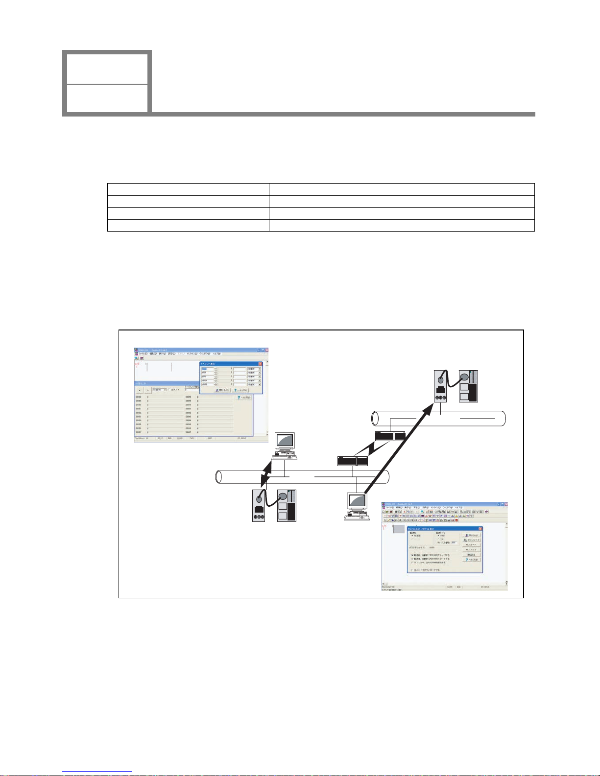
● Remote Maintenance Function
Using the Web Server Unit and WindLDR version 4.70 (or a later version) enables Ethernet-based MicroSmart
ladder progr
am reading/writing and operand read/write operations.
1_1_1_Remote_Control_Over view_E
Block diagram of remote maintenance (WindLDR)
Ethernet
Ethernet
User program download
Rout er
Router
Web Server Unit + MicroSmart
Web Server Unit + MicroSmart
Monitor Dialog
Download di alog
Read / Write of the operand
CHAPTER 1
OVERVIEW
Web Server Unit Overview
1
Phone: 800.894.0412 - Fax: 888.723.4773 - Web: www.clrwtr.com - Email: info@clrwtr.com
Page 8
1-3
● Web Server Function
The Web server’s sample screens or user creation screens enable MicroSmart operand read/write op
erations from a
Web browser.
1_1_2_Remote_Control_Over view_E
Block diagram of remote monitoring (Web browser)
Ethernet
Ethernet
Rout er
Router
Web Server Unit +MicroSmart
Web Server Unit + MicroSmart
Simple Monitor / Web Browser
Operand Monitor / Web Browser
Read/Write of the operand
Read/Write of the operand
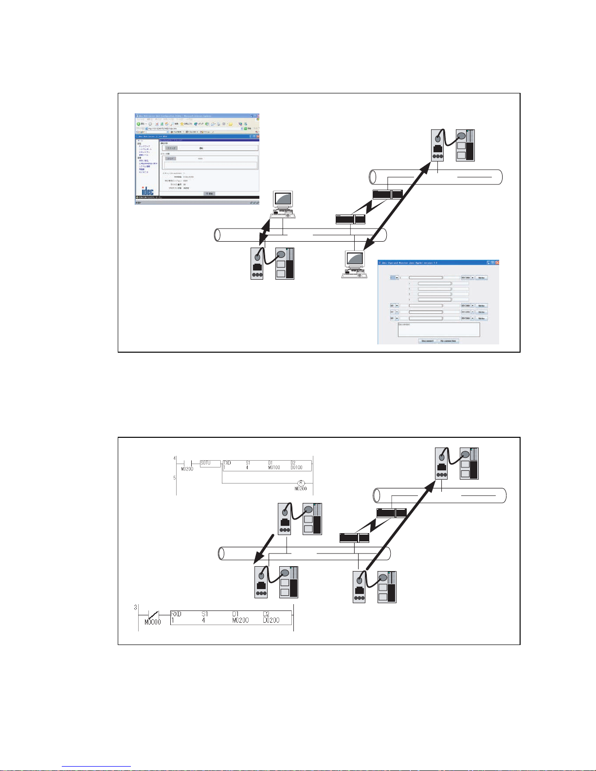
● Ethernet User Communication Function
The Web Server Unit function and MicroSmart user communication commands enable Ethernet-based 1:1
communication between Micro
Smart modules.
1_1_3_Microsmart_communication_overview_E
Block diagram of communication between MicroSmart modules
Ethernet
Ethernet
Rout er
Rout er
Web Server Un it + MicroSmart
Transmit data
with TXD command
Receive data
with RXD command
Transmit data
with TXD command
Receive data
with RXD command
Phone: 800.894.0412 - Fax: 888.723.4773 - Web: www.clrwtr.com - Email: info@clrwtr.com
Page 9
1-4
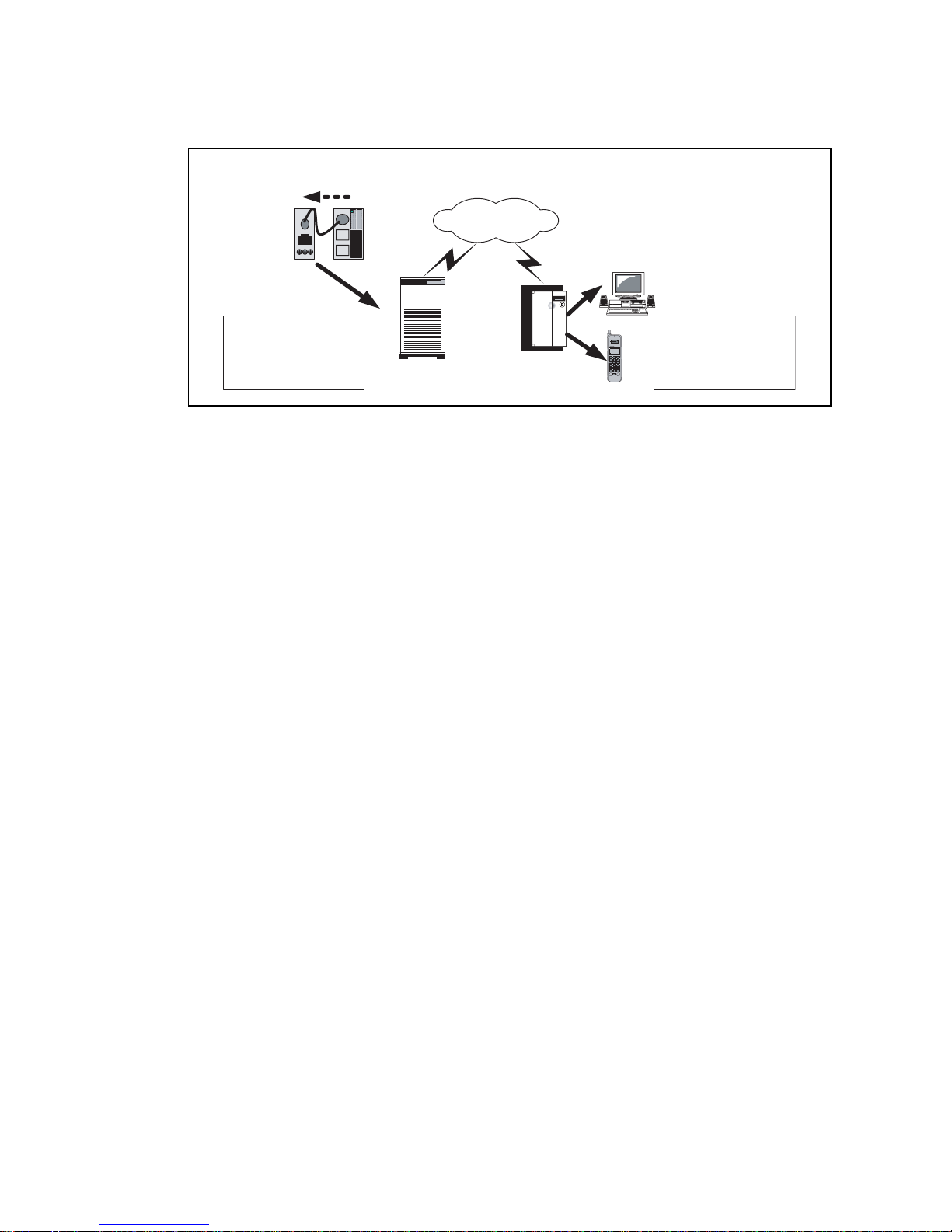
● Message Sending Function
The W eb Server Unit function and MicroSmart user communication commands enable message (mail) sending to a
PC
or mobile phone.
1_1_4_Massagesend_Overview_E
The Internet
E-mail
To: AAA@BBB
Subject: ERROR
Transmit the t rigger signal
of sen ding alarm mail
E-mail
From: CCC@DDD
Subject: ERROR
Mail server
Mail server
Block diagram of mail transmission
■ Network Cautions
● Caution when connecting
The Web Server Unit has to be used on the local network. When accessi
ng the PLC via network using the Web
Server Unit function, it takes time to transfer the data in some communication environments. Be sure to set the
timeout value in the PLC communication settings.
As regards the network connection, please co
nsult with the n
etwork administrator.
● Security Caution
The W eb Server Unit’s user name and password authentication function will
not completely prevent unauthorized
access.
● Limitation on User Screen Creation
User screen sample pages are provided, but kno
wledge of Java applets is needed to modify sample screens to create
original pages. See the Sun Microsystems Inc. web site for more information on Java applets.
Phone: 800.894.0412 - Fax: 888.723.4773 - Web: www.clrwtr.com - Email: info@clrwtr.com
Page 10

2-1
CHAPTER 2 SPECIFICATIONS
This chapter contains information on the Web Server Unit’s specifications. Familiarize
yourself with the information in this chapter to ensure effective use of the Web Server
Unit.
Phone: 800.894.0412 - Fax: 888.723.4773 - Web: www.clrwtr.com - Email: info@clrwtr.com
Page 11
2-2
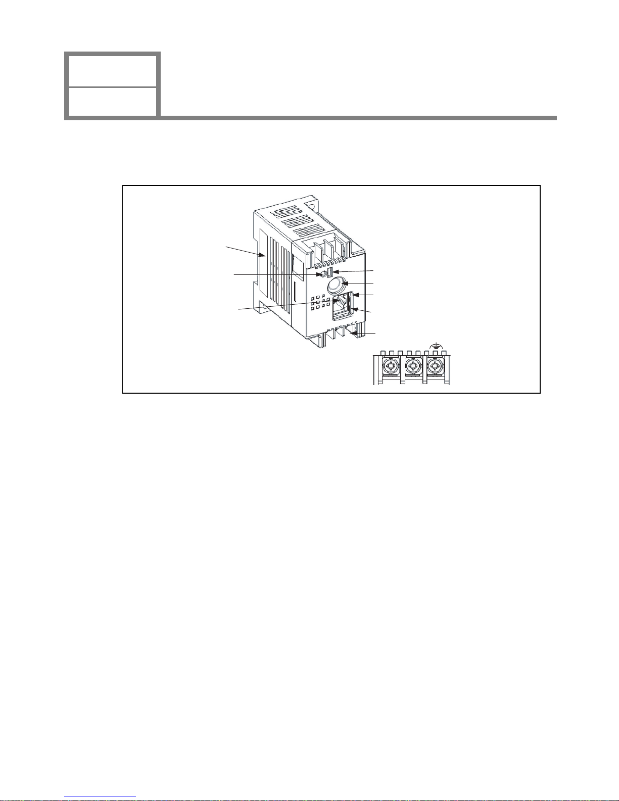
This section provides the names and specifications of Web Server Unit components.
■ Names
2_1_1_System_Configration_E
System configuration diagram
(1)Format label
(2)Power display
LED (PWR)
(4) Function selector switch
(5) MicroSmart connection port
(6) LINK LED
(7) Network LED
(8) Terminal Name
+
-
(3)Ethernet port
1) Format label
Indicates the Web Server Unit model No./type.
2) Power display LED ; Green (PWR)
Lights when power is being supplied to the Web Server Unit.
3) Ethernet port
The port into which the ends (RJ-45) of the Ethernet cable is inserted.
4) Functio
n selector switch
Used to switch the Web Server Unit’s function.
When using the remote maintenance function and the Web server functi
on, set the switch to “REMOTE”.
When using the Ethernet user communication function and the mail sending functio
n, set the switch to “USER”.
*The default setting is “REMOTE”.
5) MicroSmart connection port
Serial communication port connecting the W
eb Server Unit and MicroSmart.
6) LINK LED
Lights when the cable is connected to the Web Server Unit.
7) Net
work LED
Flashes when the Web Server Unit is sending/receiving data.
8) Termin
al name
Indicates the terminal name.
CHAPTER 2
SPECIFICATIONS
Names and Specifications of Module Components
1
Phone: 800.894.0412 - Fax: 888.723.4773 - Web: www.clrwtr.com - Email: info@clrwtr.com
Page 12
CHAPTER 2
SPECIFICASIONS
Performance Specifications
2
2-3
This section provides the Web Serv er Unit’s performance specifications.
■ General Specifications
● Normal Operating Conditions
Model type FC4A-SX5ES1E
Operating Temperature
(Operating ambient
tem
perature)
0 to 55°C
Storage Te m perature
−25 to +70°C (non-freezing)
Relative Humidity 10 to 95% (non-condensing)
Pollution Degree 2 (IEC60664-1)
Degree of Protection IP20 (IEC60529)
Corrosion Immunity Free from corrosive gases
Altitude
Operation: 0 to 2,000m (0 to 6,565 feet)
T
ransport: 0 to 3,000m (0 to 9,840 feet)
Vibration
Resistance
When
mounted on a
DIN rail:
5 to 9Hz amplit
ude 3.5mm,
9 to 150Hz acceleration 9.8m/s
ec
2
2 hours per axis on each of three mutually perpendicular axes (IEC61131-2)
When
mounted on a
pane
l
surface:
Shock Resistance
147m/sec2 (15G) 11msec duration, on three mutually perpendicular axes
(IEC61131-2)
Antistatic discharger Contact: ±6kV, Aerial: ±8kV (IEC61
000-4-2)
● Power Supply
Rated Power Voltage 24V DC
Allowable Momentary Power
Interruption
Greater than or equal to 10msec (at 24V DC)
Dielectric strength
Between power and
terminal
500V AC 1 minutes
Insulation resistance
Between power and
terminal
Greater than or equal to 10MΩ (500V DC megger)
Noise Resistance
DC power terminals
1.0kV, 50nsec to 1
µsec (Direct connecting)
Ethernet cable
0.5kV, 50nsec to 1
µsec (Coupling clamp)
Grounding
100Ω
Grounding wire UL1007 AWG16
Power Supply Wire UL1015 AWG22, UL1007 AWG18
Effect of Improper Power
Supply Connection
Rever s e po l arity No operation, no damage
Improper voltage or
frequency
Permanent damage may be caused
Improper lead connection Permanent damage may be caused
Weight 120g
Phone: 800.894.0412 - Fax: 888.723.4773 - Web: www.clrwtr.com - Email: info@clrwtr.com
Page 13
2-4
● Communication Functions
Serial
Standards Compatible with the EIA RS232C standard
Baud Rate 9,600bps (Default) to 115,200bps
Synchro system Asynchronous communication method
Transmission method Full duplex
Ethernet
Standards Compatible with the IEEE802.3 standa
rd
Transmission rate
10BASE-T
100BASE-TX (Out of
the standard coverage)
*1.Depending on the noise environments, Web Server Unit cannot communicate on the 100BASE-TX in
some cases.
*1
Communication protocol
IP/ICMP/ARP/TCP
*2.The number of unit to be connected at the same moment is one unit.
*2
/SMTP/HTTP/Telnet
● Functions
Web Server
Supported Web Browser
Internet Explorer 6.0 or later
Netscape Navigator 7.2 or later
Java VM Versions 1.42 or later
Alarms
Alarm contents Alarm contents have to be registered in the Web Server Unit in advance.
The number of alarm types 32 types
Alarm character strings Within 63 characters (1 byte character)
The number of destination
ad
dresses
2 addresses (The sum of two address characters is up to 64 characters)
● Connectable Unit
*1.The PLC requires the connecting cable type, FC4A-KC3
C, to connect to the Web Server Unit.
PLC
*1
FC2A series
*2.Except for Micro3 in FC2A series.
*2
, FC3A series, FC4A series
Programmable Display
*3,*4
*3.The programmable display requires the connecting cable type, HG9Z-3C125, to connect to the Web
Server Unit.
*4.The programmable display requires the firmware versions 1.
8 or later.
*5.Please contact IDEC for more detail.
HG2F
*5
Phone: 800.894.0412 - Fax: 888.723.4773 - Web: www.clrwtr.com - Email: info@clrwtr.com
Page 14

3-1
CHAPTER 3 MODULE OPERATION
This chapter provides an overview of the operation method, and contains information
on parameters and sample programs. Familiarize yourself with the information in this
chapter to ensure effective use of the Web Server Unit.
Phone: 800.894.0412 - Fax: 888.723.4773 - Web: www.clrwtr.com - Email: info@clrwtr.com
Page 15
3-2
This section describes how to set the Web Server Unit.
■ Setting Procedure
The following settings are needed to connect the Web Server Unit to Ethernet and operate its functions.
System Configuration
System Setting Screen
Network Address Setting Procedure
Serial Communication Setting Procedure
Other Function Settings
1) Security
2) Mail Sending
3) Administration
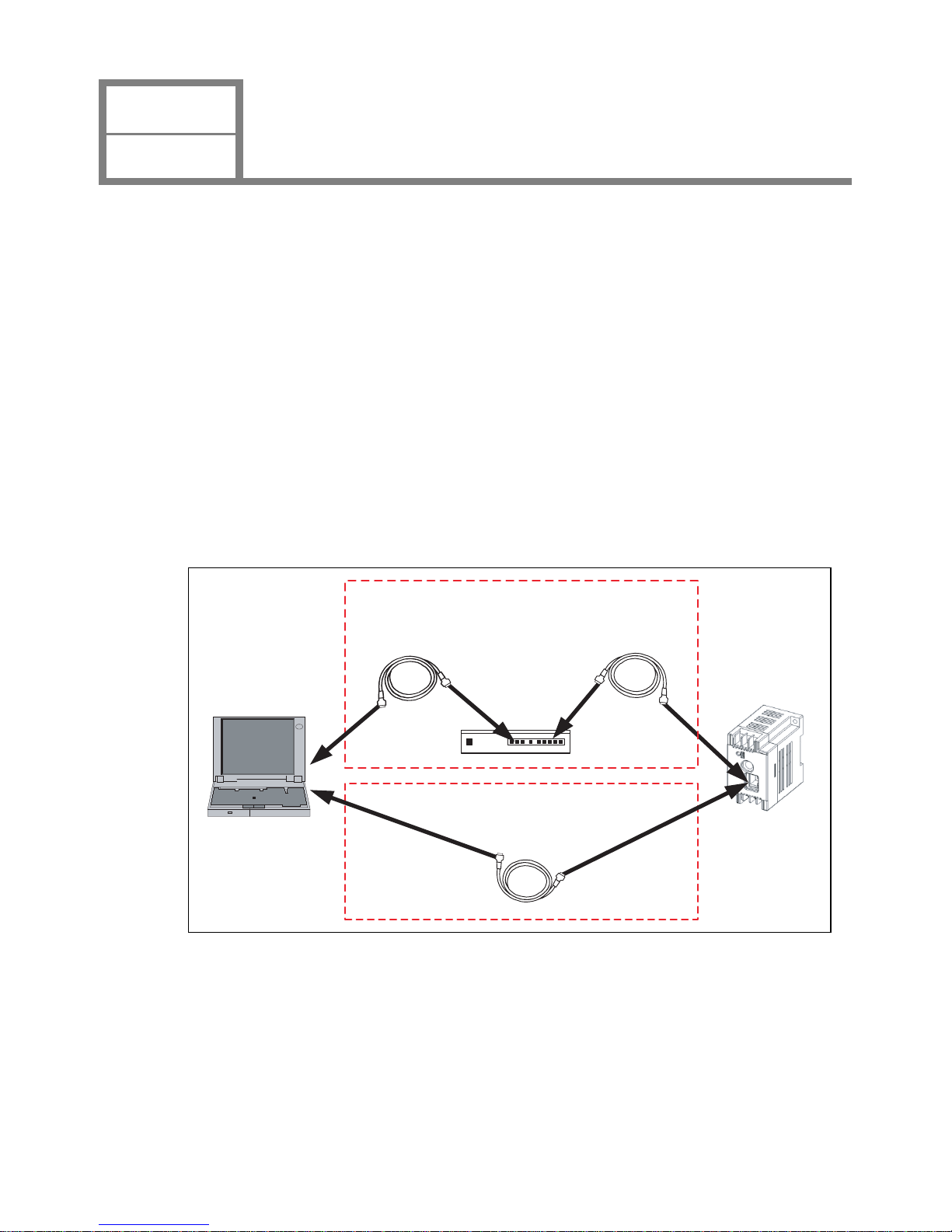
● System Configuration
Use the following either methods to connect the Web Server Unit to a PC* with WindLDR version 4.70 (or a later
v
ersion) installed.
(1
) The connection using a Hub and Ethernet straight cables
(2) The connection using an Ethernet cross cable
Connection methods
3_1_1_Crosscable_Connection_E
Web Server UnitPersonal computer
Ethernet cross cable
Ethernet straight cable
Ethernet straight cable
Hub
(1) The connection using a Hub
and Ethernet straight cables
(2) The connection using a Ethernet cross cable
* Make sure an IP address is set for the PC. To initialize Web Server Unit from the factory default state, it is
necessary to connect the personal computer and the Web Server Unit by the same network setting. Because the
factory default IP address for the Web Server Unit is [192.168.1.5], the IP address of Personal Computer have to
be [192.168.1.1] for instance.
* The PC must be able to run a Web browser (such as Inte
rnet Explorer). Enable JavaScript and
Java applets.
* When connecting to a network such as a company LAN, consult the network administrator before conn
ecting
the W eb Server Unit.
CHAPTER 3
MODULE OPERATION
Web Server Unit Settings
1
Phone: 800.894.0412 - Fax: 888.723.4773 - Web: www.clrwtr.com - Email: info@clrwtr.com
Page 16
3-3
● System Setting Screen
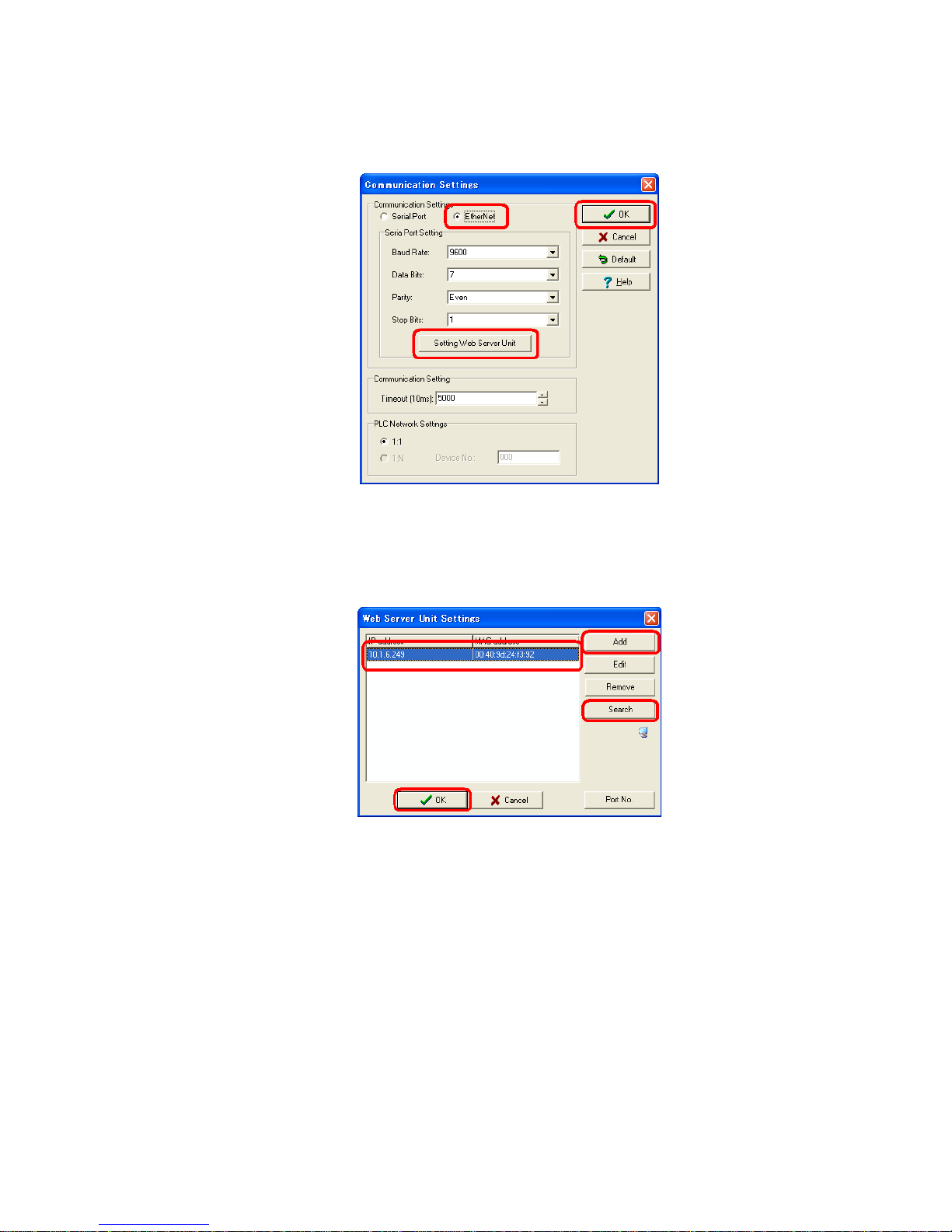
1. Select [Configure]→[Communication Settings]→[Ethernet] from the WindLDR menu and press [OK]. Then
select [Setting Web Server Unit]. *This time, the correct PLC have to be selected on the [Configure]→[PLC
Selection].
2. By pressing the [Search] button, the list of the Web Server Unit information appears in the WindLDR screen. Or
otherwise, using the [Add] button enter the IP address and add the item for the list. Then select the
communication target from the list and press [OK].
WindLDR dialog
3_1_2_WindLDR_Dialog_E
WindLDR dialog
3_1_3_WindLDR_Dialog_E
Phone: 800.894.0412 - Fax: 888.723.4773 - Web: www.clrwtr.com - Email: info@clrwtr.com
Page 17
3-4
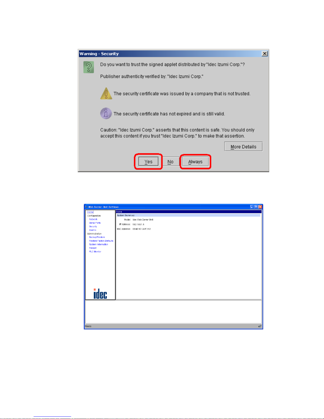
3. A warning dialog appears asking whether to start the applet. Select [Yes] or [Always]. When you select
[Always], the dialog does not appear the next time you start the Web browser.
Java applet is loaded.
4. The System Setting Screen below appears. Use it to make the settings.
3_1_4_Applet_Bootup_Warning_E
Warning dialog during Ja va applet startup
3_1_5_System_Setting_Screen_E
System Setting Screen
Phone: 800.894.0412 - Fax: 888.723.4773 - Web: www.clrwtr.com - Email: info@clrwtr.com
Page 18
Menu Description
HOME
Initial screen when the system startups. Model, IP address and MAC
address are displa
yed.
Configuration
Network Network settings
Serial Ports Serial port settings
Security Password settings
Alarms Message settings
Administration
Backup/Restore Saves and backups the set values.
Restore Factory
De
faults
Rev
erts to the default values.
System Information Displays the system information.
Reboot Restarts the system.
PLC Monitor Displays the PLC status when a PLC is connected.
3-5
The following settings are available in the System Setting Scr
een.
● Network Address Setting Procedure
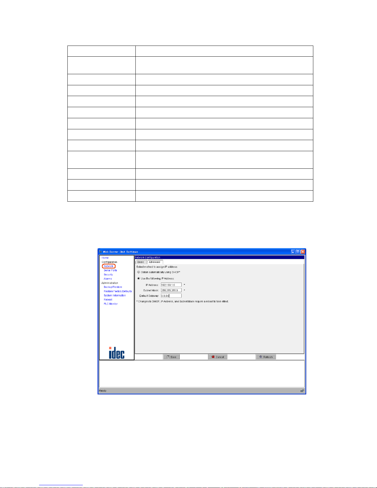
To connect the Web Server Unit to Ethernet, the IP address (the network address), subnet mask and def
ault gateway
need to be set. T o set the Web Server Unit’ s network address, open the abov e-mentioned System Setting Screen, then
select [Network] on the left menu to display the screen below. You can use either of the following methods to make
the network settings.
3_1_6_Network_Setting_E
Network settings screen
Phone: 800.894.0412 - Fax: 888.723.4773 - Web: www.clrwtr.com - Email: info@clrwtr.com
Page 19

3-6
1) Acquiring network address from DHCP server*
This method acquires the Web Server Unit’s network address from
the DHCP serv
er. In the network settings
screen, select [Obtain automatically using DHCP], and click the [Save] button. The setting is applied when you
connect to the network and then restart the Web Server Unit.
2) Fixed network address allocation
Sets a fixed user-specif i ed network address. Make sure that e
very IP address set in the same
network is unique.
In the network settings screen, select [Use the following IP Address :], and enter the desired IP address, subnet
mask and default gateway address. Click the [Save] button. The setting is applied when yo u connect to the
network and then restart the Web Server Unit.
* If there is no DHCP server in the same network used b
y the Web Server
Unit, the network address can’t be
acquired, so use method (2) to set the network address.
3_1_7_DHCPserver_network_E
When using DHCP server or not
Ethernet
Ethernet
Personal
computer
Router
DHCP server
The DHCP server allocates the
network address.
When the DHCP server and the Web Server Unit
are in the same network.
It operates on the network address
allocated by the DHCP server.
When the DHCP server and the Web Server Unit
are not in the same network.
It operates on the network address
that is set by the user.
Phone: 800.894.0412 - Fax: 888.723.4773 - Web: www.clrwtr.com - Email: info@clrwtr.com
Page 20

3-7
● Serial Communication Setting Procedure
The W eb Server Unit and PLC are connected by serial communication. Settings
such as the baud rate, data length,
stop bit, parity bit and flow control are needed. To set Web Server Unit serial communication, open the System
Setting Screen, and select [Serial Ports] on the left menu to display the screen below.
The MicroSmart serial com
munication def
aults are shown below. Normally, there is no need to change the initial
values of these items.
3_1_8 Serial_Port_Setting_E
Serial port communication settings
Baud Rate: 9600 bps
Data Bits: 7 bits
Parity: Even
Stop Bits: Bit 1
Flow Control:None
Phone: 800.894.0412 - Fax: 888.723.4773 - Web: www.clrwtr.com - Email: info@clrwtr.com
Page 21

3-8
● Other Function Settings
The other Web Server Unit settings are described below.
1) Security
Sets the user name and password. The setting is enabled to open the system screen or to use WindLDR for
communication. The settings are applied after bei
ng saved.
3_1_9_Password_Setting_E
Password setting
Checking the [Enable password authentication] check box allows you to input the user name and password.
2) Mail Sending
Used to send messages from external devices as specified by the startup conditions. See Sec
tion 3-5, “Mail
Sending Function”.
3) Administration
Backup/Restore: Used to save or restore the current Web Server Unit settings.
Restore Factory Def
aults: Restores the Web Server Unit to the settings i
t had at the time of factory shipment.
System Information: Displays the Web Server Unit’s system information.
Reboot: Restarts the Web Server Unit.
PLC Monitor: Displays the connected PLC’
s status information.
Phone: 800.894.0412 - Fax: 888.723.4773 - Web: www.clrwtr.com - Email: info@clrwtr.com
Page 22

3_1_10_PLC_Monitor_E
PLC monitor
3-9
Phone: 800.894.0412 - Fax: 888.723.4773 - Web: www.clrwtr.com - Email: info@clrwtr.com
Page 23

CHAPTER 3
MODULE OPERATION
Remote Maintenance Function
2
3-10
This section describes the Web Server Unit’s remote maintenance function. Use this function to perform
remote PLC maintenance from WindLDR via the Web Server Unit.
■ System Configuration Example
Use Ethernet to connect the Web Server Unit to a PC with WindLDR version 4.70 (or a later version) installed.
Make the network settings before han d to enable a LAN or cross-cable connection.
3_2_1_LAN_Connection_Image_E
Illustration of LAN connection
Ethernet
Ethernet
User program download
Rout er
Rout er
Web Server Unit + MicroSmart
Web Server Unit + MicroSmart
Monitor Dialog
Download di alog
Read/Write of the operand
Phone: 800.894.0412 - Fax: 888.723.4773 - Web: www.clrwtr.com - Email: info@clrwtr.com
Page 24

3-11
■ WindLDR Settings
● Communication Setting Dialog
Select [Configure]→[Communication S
ettings]→[Ethernet], and press [OK]. A dialog for selecting the Web Server
Unit is displayed the next time you start communication. Set the communication target to start.
3_2_2_Communication_setting_E
Communication setting (Selecting Ethernet)
The screen below appears when communication starts. By pressing the [Search] button, the list of the Web Server
Unit information appears in the W indLDR screen. Or otherwis e, using the [Add ] b utton enter the IP address and add
the item for the list. Then select the communication target from the list and press [OK].
3_2_3_Communication_Target_Setting_E
Communication setting (Selecting the target IP address)
Phone: 800.894.0412 - Fax: 888.723.4773 - Web: www.clrwtr.com - Email: info@clrwtr.com
Page 25

3-12
■ Web Server Unit Settings
To perform remote maintenance, the Web Server Unit’s network settings must enable connection, as shown below.
● Network Services Settings
TCP/IP port 2101 ON (default). You can access [Network Services
] from [Configuration] → [Serial Ports] →
[Network Services].
3_2_4_TCP_IP_Setting_E
TCP/IP settings
● Serial Settings
Leave at the default settings. You can access from [Configuration] → [Ser
ial Ports] → [Basic].
3_2_5_Serial_Setting_E
Serial settings
Phone: 800.894.0412 - Fax: 888.723.4773 - Web: www.clrwtr.com - Email: info@clrwtr.com
Page 26

3-13
■ Remote Maintenance From WindLDR
You can perform PLC remote maintenance from WindLDR via the Web Server Unit. Among the online functions
supported by the serial port, the functions below can be used on the network.
• Online Monitor
• Communication Error
• Upload Program
• Verify Program
• Download Program
• Partial Program Download
In some communication environments, it takes time to transfer the data. Set the timeout
v
alue in the WindLDR c
ommunication settings and PLC communication settings as
needed.
If the communication time-out occurs at ti me of do wnload b y w a y of W eb Server Unit , set
th
e time-out v
alue - [Configure]→[Communication Settings]→[Timeout] - longer than the
current value. For reference, if the program size is 32 KB, the time-out value is greater
than or equal to 2,400×10m sec, though this value is somewhat different depending on
the network situations.
When user name/password authentication is s
et in the Web
Server Unit, you will be
prompted for authentication during WindLDR communication access. Enter the user
name and password. Communication starts when authentication has been performed.
■ SCADA Software/OPC Server
Using the Web Server Unit with an OPC server or SCADA that supports Ethernet enables Ethernet-based
MicroSmart data reading/writing. This feature enables graphical operation monitoring, and servicing/maintenance
with an outstanding GUI.
Confirmed software
WindSRV, IDEC Corporation
For more detail, please contact IDEC.
NOTE
Phone: 800.894.0412 - Fax: 888.723.4773 - Web: www.clrwtr.com - Email: info@clrwtr.com
Page 27

CHAPTER 3
MODULE OPERATION
Web Server Function
3
3-14
The Web Server Unit’s Web server function enables operations such as PLC monitoring using a Web
browser with Java applets.
■ PLC Operand Monitor
A PLC operand monitor is provided as a sample program. The PLC operand monitor is not installed in the Web
Server Unit with the initial settings at time of factory shipment. You must upload the sample PLC operand monitor
from the CD-ROM provided.
● System Configuration Example
First make the network settings, then connect the Web server to a PC with a Web browser usi
ng a LAN or cross
cable. When monitoring, MicroSmart should be connected to the Web Server Unit and activated.
3_3_1_LAN_Connection_Image_E
Illustration of LAN connection
Ethernet
Ethernet
Rout er
Router
Web Server Unit + MicroSmart
Web Server Unit + MicroSmart
Simple Monitor / Web Browser
Operand Monitor / Web Browser
Read/Write of the operand
Read/Write of the oper and
The PC must be able to run a Web browser (such as Internet Explorer), and JavaScript and Java applets must be
enabled.
● Web Browsers
Confirmed Web browsers:
Internet Explorer 6.0, Netscape 7.1
* The Java VM running environment is required.
● Uploading PLC Monitor Sample Scr
een
How to
upload the PLC monitor screen is described below. At time of factory shipment, the PLC monitor screen is
not installe
d in the Web Server Unit. (Use the Java Applet Monitor from the CD-ROM.)
Due to restrictions on server file volume capacity, the System Setting Screen and Java applet monitor can’t coexist.
How to upload the sample program (Java applet) is described bel
ow, u
sing Internet Explorer 6.0 as an example.
1. Start Internet Explorer.
Phone: 800.894.0412 - Fax: 888.723.4773 - Web: www.clrwtr.com - Email: info@clrwtr.com
Page 28

3-15
2. In the address bar, enter the Web Server Unit’s IP address and the file name, as shown below (example: when
the IP address is 192.168.1.101). The settings screen for management appears.
http://192.168.1.101/home.htm
The screen below appears.
3_3_2_Master_Setting_E
Settings screen for management
3. Open the [File Management] screen and delete the files currently in the server. Select [File Management] from
the menu on the left. The screen below appears.
3_3_3_File_Management_E
File Management screen
Phone: 800.894.0412 - Fax: 888.723.4773 - Web: www.clrwtr.com - Email: info@clrwtr.com
Page 29

3-16
4. Check all files under [Manage Files], and click [Delete]. The files are deleted and the screen below appears.
5. You are now ready to upload the files. Upload the two files below. The sample program consists of the applet
that generates the monitor screen and the HTML file that runs the applet.
3_3_4_Delete_Files_E
Screen after the files are deleted
3_3_5_1_File_Folder_E
Instruction
Manual
Setting Files
Sample
Program
-
index.htm
operandapp.jar
CD
Phone: 800.894.0412 - Fax: 888.723.4773 - Web: www.clrwtr.com - Email: info@clrwtr.com
Page 30

3-17
6. Click the [Browse...] button, and select the desired file by clicking on it. Click the [Upload] button. Repeat this
process to upload the two files. When uploading has finished, the screen below appears.
7. Click [Home] on the left menu. To mak e the screen the initial screen, click [Set as Default] in the screen below.
The next time you open the Web browser, the default screen displayed when this server is accessed will be the
PLC operand monitor. (Restart the Internet Explorer.)
3_3_5_Upload_Files_E
Screen after uploading the file is completed
Set as Default screen
3_3_6_Set_As_Default_E
Phone: 800.894.0412 - Fax: 888.723.4773 - Web: www.clrwtr.com - Email: info@clrwtr.com
Page 31

3-18
8. To restore the original system setting screen, repeat Steps 1 to 4 to delete all the files, then upload all the files
below by the method of Step 6. Next, click 'Set as Default' as in Step 7 to make the system setting screen the
default screen.
● PLC Operand Monitor
An operation example using the sample program (Ja
va applet) is give
n below. This example is for Internet Explorer
6.0.
1. Enter the Web Server Unit’s IP address in the address bar as shown below (exam
ple: when the IP address is
192.168.1.101).
http://192.168.1.101/
2. The initial screen starts the sample program (PLC operand monitor). Program downloading starts, and a
warning dialog appears asking whether to start the applet. Select [Yes] or [Always]. If you select [Always], this
dialog will not appear the next time the sample program starts.
3_3_5_1_File_Folder_E
Instruction
Manual
-
inde x.htm
comm on.jar
CD
Setting
Files
Sample
Program
configapp.jar
config.ini
3_3_7_Warning_Dialog_E
Warning dialog
Phone: 800.894.0412 - Fax: 888.723.4773 - Web: www.clrwtr.com - Email: info@clrwtr.com
Page 32

3-19
3. IDEC operand monito r starts. If you have set the user name and password in the Web Server Unit in advance,
you are prompted to enter them.
4. You can no w perform operand monitoring and writing. Select the operand type and enter the address. Addresses
are 4 digits. Five consecutive addresses can be written or monitored at the top part. Enter the values in the input
field and press the [Write] button to write the values.
Operand types
I/X Input (word) i/x Input (bit)
Q/Y Output (word) q/y Output (bit)
M Internal relay (word) m Internal relay (bit)
R Shift register (word) r Shift register (bit)
T Timer (set value)
t Timer (count value)
C Counter (set value)
c Counter (count value)
D Data register
Display formats
DEC(W) Decimal (unsigned) DEC(I) Decimal (signed)
DEC(D) Decimal (unsigned), 2 words DEC(L) Decimal (signed), 2 words
HEX(W) Hexadecimal HEX(D) Hexadecimal, 2 words
BIT Bit
• The PLC operand monitor screen is stored in the Web Server Unit, but executed by the
PC.
• The Java applet performs communication between the PC it runs on and the Web
Server Unit.
• The W
eb Server Unit relays commands receiv ed on Ethernet (TCP/IP) to the PLC, and
returns the PLC's reply on Et
hernet (TCP/IP).
NOTE
3_3_8_Operand_Monitor_E
Operand Monitor Java Applet
Phone: 800.894.0412 - Fax: 888.723.4773 - Web: www.clrwtr.com - Email: info@clrwtr.com
Page 33

3-20
■ User Screen Creation
The original PLC monitor screens can be made and built into the Web Server Unit. Also the sample page can be
referred to this programming. To make these screens, the knowledge for Java Applet is required. For more
information, see the Sun Microsystems Inc. web site.
● Sample Program Creation Environment
The sample program PLC operand monitor was created on
Java 2 SDK Standard Edition version 1.4.2, and Ant 1.6.
● Creating/Uploading
The sample program source code is included in the CD-ROM provided. The CD-R
OM also includes referential
materials such as the Java.doc file.
To upload a created HTML file or Ja
va appl
et, see the previous section of “Uploading PLC Monitor Sample
Screen”.
• Security precautions and other adaptations should be made when running them on the network.
CAUTION
!
• Sample programs are provided as is, and their operation is not always guaranteed.
Phone: 800.894.0412 - Fax: 888.723.4773 - Web: www.clrwtr.com - Email: info@clrwtr.com
Page 34

CHAPTER 3
MODULE OPERATION
Ethernet User Communication Function
4
3-21
This section describes Ethernet user communication for the Web Server Unit.
MicroSmart user communication can support Ethernet via the Web Server Unit.
■ System Configuration Example
Ethernet user communication enables the Web Server Unit to communicate between MicroSmart modules or
communicate with another device (with an IP address set).
3_4_1_Ethernet_User_Communication_E
Example of a system configuration f or Ethernet user communication
Ethernet
Ethernet
Rout er
Rout er
Web Server Unit + MicroSmart
Transmit data
with TXD command
Receive data
with RXD command
Transmit data with
TXD command
Receive data
with RXD command
.
Conditions for Ethernet user communication
1) Remote comm unication device
The Ethernet user communication feature enables user communication using the TCP
protoco
l client function. A device with a TCP protocol server function must be selected as
the remote communication device.
2) Number of remote communication devices
Ethernet user communication can only be performed wi
th the registered IP address po
rt No.
In other words, there can only be one remote communication device.
3_4_2_User_Communication_E
Conditions for Ethernet user communication
Ethernet
Data transmissio n
Data reception
Only one communication
target is avail able.
NOTE
Phone: 800.894.0412 - Fax: 888.723.4773 - Web: www.clrwtr.com - Email: info@clrwtr.com
Page 35

3-22
■ Web Server Unit Settings
Follow the procedure below to make the Web Server Unit settings.
● Switching Web Server Unit Mode
Turn the Web Server Unit’s mode selection switch to “USER”.
* The default setting of the Web Server Unit’s mode selection switch is “REMOTE”.
3_4_3_Toggle_Switch_E
Function selector switch
USER
Make the switch the “USER”!
REMOTE
Performing Ethernet user communication between MicroSmart modules
T o p erform Et hernet u ser commun ication between Micro Smar t modul es, the onl y operat io n needed
for the Web Server Uni
t on the TCP protocol server is to set the mode selection switch to “USER”.
The rest of the setting procedure is giv en i n the descri ption of t he TCP prot ocol client sett ings.
● Opening Web Server Unit System Setting
Screen
Open the W eb Server U
nit’s settings screen.
There are two ways to open this screen:
1) Opening settings screen from WindLDR (see “System Setting Screen” in Section 1 of Chapter 3 for more inf
ormation)
1. Select [Setting Web Server Unit] in WindLDR.
2. The previously
set IP address appears in the WindLDR screen.
3. Doub le-click the IP address of the Web Server Unit performing Ethernet user communication. The Web
browser starts, and the System Setting Screen as below appears.
2) Opening setting s screen directly from Web browser
1. Start the Web browser.
2. In the Web browser’s address bar, enter the IP address of the Web Server Unit performing Ethernet user
communication, and press the Web browser’s [Refresh] button or the keyboard’s Enter key.
3. The System Setting Screen appears.
NOTE
3_4_5_System_Setting_E
System Setting Screen
Phone: 800.894.0412 - Fax: 888.723.4773 - Web: www.clrwtr.com - Email: info@clrwtr.com
Page 36

3-23
● Setting TCP Client Mode
1. Specify [Serial Ports] in the left menu of the system setting screen, and select the [Port Services] tab.
2. Check the [TCP Client]- [Enable TCP client service] check box.
3_4_6_System_Setting_Screen_Alarms_E
Port Services
3_4_7_Alarm_IP_Address_E
Enable TCP client service
Phone: 800.894.0412 - Fax: 888.723.4773 - Web: www.clrwtr.com - Email: info@clrwtr.com
Page 37

Difference betwe en [Always] and [When data present on serial line]
[Always] and [When data present on serial line] each specify a dif
ferent timing for sending the
request to establish the communication path to the remote communication device.
Item Timing for sending request to establish communication path
Always When power is turned ON
When data present on serial line When register ed data is received from serial line
When [When data present on serial line] is selected
The registered character string used to star
t Ethernet user communication is the trigger for sending
a communication path establishment request to the remote communication device. It is also data
sent to the remote communication device. In other words, the registered character string is sent to
the remote communication device. If this registered character string is not needed by the remote
communication device, it must be deleted by the remote communication device’s settings or
receiving program.
3-24
3.
Select [Always] or [When
data present on serial line].
4. When selecting [When data present on serial line], enter the character string used for starting Et
hernet user
communication in the [initial match string] field.
You can enter up to 31 characters (only single-byte alphanumeric characters).
NOTE
NOTE
3_4_8_Portservice_TCP_Cliant_E
TCP client connecting conditions
3_4_9_Initial_Match_String_E
Enlarged character string input screen
Phone: 800.894.0412 - Fax: 888.723.4773 - Web: www.clrwtr.com - Email: info@clrwtr.com
Page 38

3-25
5. Click the [Save] button, and the [Reboot] button on the left menu to complete the setting procedure.
3_4_10_Portservice_reboot_E
Reboot screen
Phone: 800.894.0412 - Fax: 888.723.4773 - Web: www.clrwtr.com - Email: info@clrwtr.com
Page 39

3-26
■ MicroSmart Settings
MicroSmart user communication commands are used to perform Ethernet user communication.
● User Communication Command Settings
For more information on user communication, see Chapter 17, “User Communication
Ins
truct
ions” in the MicroSmart instruction manual.
1. Set the MicroSmart port for performing Ethernet user communication (1st or 2nd port).
In WindLDR, select [Configuration] → [Function Area S
ettings] → [Communication] tab.
Select the port to use for Ethernet user communication under [User Protocol].
3_4_11_Usercom_Port_Setting_E
User protocol selection
2. Enter the user communication command in the ladder program.
Enter the TXD command or RXD command in the ladder program.
3_4_12_TXD_RXD_Command_E
TXD and RXD commands in a ladder program
3. Download the ladder program.
In WindLDR, select [Online] → [Downloa
d Program...] → [Download].
When [When data present on serial line] is set in the Web Server Unit settings
When [When data present on serial line] is set for the Web Server Unit’s TCP client mode, be sure
to make the character s
tring registered in the W eb Serv er Unit the same as the character string data
used by the TXD command. Ethernet user communication is only possible when the strings are
the same.
NOTE
NOTE
Phone: 800.894.0412 - Fax: 888.723.4773 - Web: www.clrwtr.com - Email: info@clrwtr.com
Page 40

3-27
■ Ethernet User Communication Sample Program
● Communication Between MicroSmart Modules
System configuration
3_4_15_Between_Microsmart_E
Communication between MicroSmart modules
Ethernet
Web Server Unit B
IP address: 192.168.1.5
TCP protocol server mode
IP address: 192.168.1.5
(1) Data transmission
(2) Data rece ption
(3) Data transm ission
(4) Data rece ption
The setting of Web Server Unit A
IP address: 192.168.1.2
TCP protocol client mode: "Always"
Target IP address: 192.168.1.5
Service: RAW
Connected Port No.: 2101
MicroSmart A
MicroSmart B
Web Server Unit A: TCP protocol (Client mode)
Web Server Unit B: TCP protocol (Server mode)
MicroSmart A
MicroSmart B
1) MicroSmar t A transmits data with the TXD command, and becomes
ready to receive data with the
RXD
command. Web Server Unit A transmits the data sent from MicroSmart A to Web Server Unit B (to which the
target IP address, the service and the target port number are registered).
2) Web Server Unit B receives the data addressed to it, and transmits data to MicroSmart B. MicroSmart B
receives the data with the RXD
command.
3) MicroSmar t B transm its data wi th the TXD command. Web Server Unit B transmits the data sent from
MicroSmart B to Web Serv
er Unit A.
4) Web Server Unit A receives the data addressed to it and transmits data to MicroSmart A. MicroSmart
A receives
data with the RXD command.
Phone: 800.894.0412 - Fax: 888.723.4773 - Web: www.clrwtr.com - Email: info@clrwtr.com
Page 41

3-28
● Sample Ladder Program
MicroSmart on Web Server Unit A side
3_4_16_Between_Microsmart_Sample_E
If the start input M0000 is turned on, MicroSmart transmits 4-byte data from port 2, and becomes ready to receive
data.
MicroSmart on Web Server Unit B side
3_4_17_Between_Microsmart_Sample_E
When it finishes receiving 4-byte data from port 1, and then transmits 4-byte data from port 1.
Phone: 800.894.0412 - Fax: 888.723.4773 - Web: www.clrwtr.com - Email: info@clrwtr.com
Page 42

CHAPTER 3
MODULE OPERATION
Mail Sending Function
5
3-29
This section describes the Web Server Unit’s mail sending function.
You can use MicroSmart’s user communication functions to send messages to devices that can receive
mail from PCs or similar devices.
■ System Configuration Example
3_5_1_Message_Sending_System_E
Configuration example of mail transmission system
The Internet
E-mail
To: AAA@BBB
Subject: ERROR
Transmit the t rigger signal
of sen ding alarm mail
E-mail
From: CCC@DDD
Subject: ERROR
Mail server
Mail server
Conditions for using mail sending functi on
1) Mail server
A mail server IP address is needed to send messages. Ask your network admini
strator for
your mail server IP address.
NOTE
Phone: 800.894.0412 - Fax: 888.723.4773 - Web: www.clrwtr.com - Email: info@clrwtr.com
Page 43

2) Messages
• The character strings registered in the Web Server Unit (up to 63 sing
le-byte
alphanumeric characters) can be sent as messages utilizing the subject column of the Email.
• The message body is fixed to “Data Pattern Alarm”.
• You can specify up to 32 dif
ferent messages (subjects), with 2 recipient mail addres
ses
for each.
• You can set recipient mail addresses of up to
64 single-byte alphanumeric characters.
• Mail sending timing: Messages are sent only when the character string registered in the
Web Server Unit is receiv
ed from the serial line.
3_5_2_Message_Sending_Condition_E
Illustration of mail transmission
12:00
26 May 13:15
Sub: Temp. High
Data Pattern Alarm
From: WebAlart@idec
To: abcdefg1234@idec;
hijkim5678@idec
From: WebAlart@idec
Subject: Temp. High
Data Pattern Alarm
3-30
■ Web Server Unit Settings
Follow the procedure below to make the Web Server Unit settings.
● Switching Web Server Unit Mode
Set the Web Server Unit’s mo de selection switch to “USER”.
* The default set
ting of the Web Server Unit’s mode selection switch is “REMOTE”.
3_5_3_Toggle_Switch_E
Function selector switch
USER
Make the switch the “USER”!
REMOTE
● Opening Web Server Unit System Setting Screen
Open the W eb Server Unit’s setting screen.
There are two ways to open this screen:
1) Opening setting s screen from WindLDR (see “System Setting Screen” in Section 1
of Chapter 3 for more
information).
1. Select [Setting Web Server Unit] in WindLDR.
2. The previously set IP address app
ears in the WindLDR screen.
3. Doub le-click the IP address of the Web Server Unit performing Ethernet user communication. The Web
browser starts, and the System Setting Screen as below appears.
2) Opening setting s screen directly from Web browser
1. Start the Web browser.
2.
In the Web brow
ser’s address bar, enter the IP address of the Web Serv er Unit performing Ethernet user
communication, and press the Web browser’s refresh button or the keyboard’s Enter key.
Phone: 800.894.0412 - Fax: 888.723.4773 - Web: www.clrwtr.com - Email: info@clrwtr.com
Page 44

3_5_5_System_Setting_E
System Setting Screen
3-31
3. The System Setting Screen appears.
Phone: 800.894.0412 - Fax: 888.723.4773 - Web: www.clrwtr.com - Email: info@clrwtr.com
Page 45

3-32
● Alarms
1. Specify [Alarms] on the left menu of the system setting screen, and check the [Enable sending alarms] check
bo
x.
2. Enter the mail server’s IP address in the [SMTP server address] field, and the Web Server Unit’s mail address*
in the [From] field.
* Ask your network administrator for the mail address.
Mail server settings
3_5_7_Alarm_IP_Address_E
3_5_6_System_Setting_Screen_Alarms_E
Alarms
Phone: 800.894.0412 - Fax: 888.723.4773 - Web: www.clrwtr.com - Email: info@clrwtr.com
Page 46

3-33
3. Check the [Enable alarm] check box and enter the recipient mail address in the [To1:] field (and [To2:] field
when sending to two addresses).
4. Enter the message text in the [Subject] field.
NOTE
Recipient mail addresses
The total character number of target addresses, [To1:] plus [To2:], ha ve to be within 64 characters.
NOTE
Messages ([Subject] field)
The total message length for a single message is up to 63 characters.
3_5_8_Alarm_Sending_Address_E
Target address
3_5_9_Alarms_Subject_E
Subject
Phone: 800.894.0412 - Fax: 888.723.4773 - Web: www.clrwtr.com - Email: info@clrwtr.com
Page 47

Mail send timing character strings
The W eb Server Unit can register up to 32 dif ferent messages. The send timing char
acter string for
each message must be unique.
3-34
5. Select [pattern_match], and enter the message send timing character string.
6. Click the [Save] button, and the [Reboot] button on the left menu to complete the setting procedure.
NOTE
3_5_10_Alarms_Pattern_Match_E
Mail send timing character string
3_5_11_Alarms_Reboot_E
Reboot screen
Phone: 800.894.0412 - Fax: 888.723.4773 - Web: www.clrwtr.com - Email: info@clrwtr.com
Page 48

3-35
■ MicroSmart Settings
MicroSmart user communication commands are used to send messages.
● User Communication Command Settings
For more information on user communication,
see Chapter 17, “User Communication
I
nstructions” in the MicroSmart instruction manual.
1. Set the MicroSmart port for performing Ethernet user communication (1st or 2nd port).
In WindLDR, select [Configuration] → [Function Area S
ettings] → [Communication] tab.
Select the port to use for Ethernet user communication under [User Protocol].
3_5_12_Usercom_Port_Setting_E
User protocol selection
2. Enter the user communication command in the ladder program.
Enter the TXD command in the ladder program.
NOTE
3_5_13_TXD_Command_E
Example of communication command in a ladder program
Phone: 800.894.0412 - Fax: 888.723.4773 - Web: www.clrwtr.com - Email: info@clrwtr.com
Page 49

3-36
3. Download the ladder program.
In WindLDR, select [Online] → [D
ownloa
d Program...] → [Download].
Web Server Unit settings and user communication command settings
Be sure to make the Web Server Unit’s send timing character string (Pattern) th
e same as the
MicroSmart TXD command data.
3_5_14_Same_String_Setting_E
Example of character string for sending timing
NOTE
Phone: 800.894.0412 - Fax: 888.723.4773 - Web: www.clrwtr.com - Email: info@clrwtr.com
Page 50

3-37
■ Sample Program for sending messages
● System Configuration
3_5_15_Sample_System_Configration_E
Example of sending a sample mail (System config u ration)
EthernetEthernet
The setting of Web Server Unit
IP address: 192.168.1.2
SMTP server: 192.168.1.5
From: AAA@BBB
To1: CCC@BBB
Message text strings: ERROR
Pattern: temp
SMTP (mail) Server A
IP address: 192.168.1.5
Mail server B
From: AAA@BBB
To: CCC@BBB
Subject: ERROR
Data Pattern Alarm
(1) TXD command: Data transmission (temp)
(2) Transmi t the alarm mail data
to the SMTP Server
(3) Receive the alarm mail data
from the Mail Server B
(4)Personal Computer
MicroSmart:
1) MicroSmart transmits data (the alphanumeric characters: temp) with the TXD command.
Web Server Uni
t:
2) Web Server Unit compares data transmitted from MicroSmart with th
e pattern that is registered. If data are
corresponding with it, W eb Server Unit transmits the alarm mail data that is registered to the SMTP server.
Mail server:
3) Mail server transmits the alarm mail data sent from Web Server Unit to the targeted mail address.
Personal Computer:
4) The personal computer receives the mail in w
hich the subject is used as
a message character string. This string
is registered to the Web Server Unit in advance.
● Sample Ladder Program
3_5_16_Sample_Ladder_Program_E
If the start input M0200 is turned on, MicroSmart transmit the character string of “temp” from its port 1.
Phone: 800.894.0412 - Fax: 888.723.4773 - Web: www.clrwtr.com - Email: info@clrwtr.com
Page 51

3-38
CONNECTION DIAGRAM
■ PLC connecting cable (Model No.: FC4A-KC3C, Cable Length : 10cm)
● The external of cable
4_1_1_Connection_Diagram_E
MicroSmart Side Web Server Unit Side
● The pin layout of connectors
4_1_2_Connection_Diagram_E
8
7
6
3
2
1
45
● The connection diagram of cable
4_1_3_Circuit_Diagram_CabÇåe3_E
1DSR
2CTS
3SD
4RD
5RTS
6 NC
7GND
8DTR
Cover Shield
Web Server Unit Side
Pin Number
Name
Pin Number
Port 1 Port 2
1 NCRS
2 NCER
3SD
4RD
5 NCDR
6CMSW SG
7SGSG
8 NC NC
Cover Shield
MicroSmart Side
Phone: 800.894.0412 - Fax: 888.723.4773 - Web: www.clrwtr.com - Email: info@clrwtr.com
Page 52

3-39
TROUBLESHOOTING
■ The following troubles and solutions could be considered
● When power display LED (PWR) does not go on
5_1_1_Trouble_Shooting_E
The PWR LED does not go on.
Is the power supplied?
Is the PWR LED on?
Supply power.
Is the power voltage
correct?
Apply the rated voltage, 24V DC.
Is the PWR LED on?
Call IDEC for assistance. END
YES
NO
NO
NO
NO
YES
YES
YES
Phone: 800.894.0412 - Fax: 888.723.4773 - Web: www.clrwtr.com - Email: info@clrwtr.com
Page 53

3-40
● It is not possible to communicate with WindLDR
5_1_2_Trouble_Shooting_E.eps
It is not possible to
communicate with WindLDR.
Is the Ethernet cable
connected?
Connect the Ethernet
cable.
Is the PLC connection
cable connected?
Connect the PLC
connection cable.
Extend the communication
timeout value of the WindLDR!
Make the function
selector switch to the
"REMOTE".
YES
NO
Is the network address of the
Web Server Unit correct?
Set the network address
of the Web Server Unit.
(Refer to Chapter 3-1.)
Is the position of the function
selector switch the “REMOTE”?
Is the serial communications
setting of the Web Server Unit the
same as the setting of the PLC?
Set as well as the serial
communication setting of
the PLC.
Is the port of the PLC the
maintenance mode?
Make the port of the PLC
to the maintenance mode.
Extend the reception timeout
value of the PLC!
[Configure][Communication
Settings]-[Timeout]
Can you communicate with
WindLDR?
Select [Configure]-[Function Area
Settings]-[Communication][Maintenance Protocol][Configure]-[Receive Timeout] and
set the timeout value. Then
connect the PLC to the WindLDR
by the serial connection and
download the program.
Can you communicate with
WindLDR?
Call IDEC for assistance.
END
YES
YES
YES
YES
YES
NO
NO
NO
NO
NO
YES
YES
NO
NO
Phone: 800.894.0412 - Fax: 888.723.4773 - Web: www.clrwtr.com - Email: info@clrwtr.com
Page 54

3-41
● Ethernet user communication does not operate normally
5_1_3_Trouble_Shooting_E
Ethernet user communication
does not operate normally.
Is the Ethernet cable
connected?
Connect the Ethernet
cable.
Is the PLC connection
cable surely connected?
Connect the PLC
connection cable.
Make the function
selector switch to the
"USER".
YES
NO
Is the address of the transmit/
receive target correct?
Set the network address
of the Web Server Unit.
(Refer to Chapter 3-4.)
Is the position of the function
selector switch the "USER”?
Is the serial communication
setting of the Web Server Unit the
same as the setting of the PLC?
Set as well as the serial
communication setting of
the PLC.
Is the port of the PLC the user
communication mode?
Make the port of the PLC
to the user
communication mode.
Extend the reception timeout
value of the PLC!
Select [Configure]-[Function Area
Settings]-[Communication]-[User
Communication]-[Configure]-[Receive
Timeout] and set the time-out value.
Then connect the PLC to the WindLDR
by the serial connection and download
the program.
Can you communicate with
the communication target?
Call IDEC for assistance.
END
YES
YES
YES
YES
YES
NO
NO
NO
NO
NO
YES
NO
Phone: 800.894.0412 - Fax: 888.723.4773 - Web: www.clrwtr.com - Email: info@clrwtr.com
Page 55

3-42
● When the alarm mail is not transmitted
5_1_4_Trouble_Shooting_E
The alarm mail is not transmitted.
Is the Ethernet cable
connected?
Connect the Ethernet
cable.
Is the PLC connection
cable connected
Connect the PLC
connection cable.
Make the function
selector switch to the
“USER”.
YES
NO
Is the mail sending function
setting of the Web Server Unit
correct?
Set the mail sending
function of the Web
Server Unit (Refer to
Chapter 3-5.)
Is the position of the function
selector switch the “USER”?
Is the serial communication
setting of the Web Server Unit the
same as the setting of PLC?
Set as well as the serial
communications setting
of the PLC.
Is the port of the PLC the user
communication mode?
Make the port of the PLC
to the user
communication mode.
Is the alarm mail
transmitted?
Call IDEC for assistance. END
YES
YES
YES
YES
YES
NO
NO
NO
NO
NO
YES
NO
Are the pattern of the
transmission condition and the
transmission data with the TXD
command the same?
Make the pattern of
the transmission
condition the same as
the transmission data
with the TXD
command!
NO
YES
Phone: 800.894.0412 - Fax: 888.723.4773 - Web: www.clrwtr.com - Email: info@clrwtr.com
Page 56

A-1
GLOSSARY
ICMP (Internet Control Message Protoc ol)
An IP-layer protocol used to transfer error messages and control messages. Used for mutual
status confi
rmation between computers or network devices connected by TCP/IP.
DHCP (Dynamic Host Configuration Protocol)
A method of dynamically assigning IP addresses to network devices on a LAN. The DHCP
server dynamically assi
gns a single preset IP address to each network device when the device
starts.
IP (Internet Protocol) address
The 32-bit address information us
ed to identify each device on a TCP/IP network.
IP addresses
are unique numbers assigned to devices that use IP to communicate. They are used to specify the
recipient device when exchanging data.
Subnet mask
The mask value used when requesting a subnet network address from an IP address. The IP
address and subnet mask are combined by
an AND operation to obtain the subnet address.
The IP address is divided into a network address No. and host address No., and the network
address is further divide
d into the subnet.
Port No.
An auxiliary address created at a lower level than the IP address, used to connect multiple
recipients at the same time during TCP/IP comm
unication. Numbers from 0 to 65535 are used to
specify ports. Data is sent/received using the combination of IP address and port No.
TCP (Transmission Control Protocol)
The standard protocol used on the Internet. Corresponds to the OSI (Open Systems
I
ntercon
nection) reference model transport laye r. Bridges the network-layer IP and protocols
above the session layer (such as HTTP, FTP, SMTP and POP).
HTTP (Hypertext Transfer Protocol)
The protocol used between the Web browser and Web server to send and receive data such as
HTML
files.
SMTP (Simple Mail Transfer Protocol)
The protocol used to send email on a TCP/IP network.
Java
An object-oriented interpreter language developed by Sun Microsystems, Inc.
JavaScript
A script language developed by Netscape Communicati
ons Corporation. Based on Net
scape’s
LiveScript. Incorporates some Java features.
Java VM
An environment for interpreting/executing programs using intermediate codes generated by a
Java compiler.
J
ava applets
Java programs downloaded from the network by the Web browser, and embedded in and
executed by
browser windows.
Phone: 800.894.0412 - Fax: 888.723.4773 - Web: www.clrwtr.com - Email: info@clrwtr.com
Page 57

A-2
Phone: 800.894.0412 - Fax: 888.723.4773 - Web: www.clrwtr.com - Email: info@clrwtr.com
Page 58

INDEX
A
Alarms
Sending alarms .........................................3-32
B
Backup .............................................................3-8
C
Communication between MicroSmart modules 3-27
Communication settings
WindLDR ................................................3-11
Connection port ...............................................2-2
Cross-cable ......................................................3-2
D
DHCP server ....................................................3-6
E
Ethernet user communication ........................3-21
F
Function selector switch ..................................2-2
J
Java applets ....................................................3-14
L
LINK LED .......................................................2-2
M
Mail send timing ............................................3-34
Mail sending function ....................................3-29
Mail server .....................................................3-29
Messages .............................................. 3-30, 3-33
N
Network address ..............................................3-2
Network address setting ...................................3-5
Network LED ...................................................2-2
O
OPC server .....................................................3-13
Other function ..................................................3-2
P
PLC Monitor ....................................................3-8
PLC operand monitor ....................................3-18
Power display LED ..........................................2-2
R
Reboot ..............................................................3-8
Recipient mail addresses ................................3-33
Remote maintenance ............................ 3-10, 3-13
Restore .............................................................3-8
Restore Factory Defaults ..................................3-8
S
SCADA ..........................................................3-13
Security ............................................................3-8
Java applet ..................................................3-4
Password ..................................................3-13
Serial communication ......................................3-2
Serial communication setting ...........................3-7
System configuration .......................................3-2
System Information ..........................................3-8
System Setting Screen
Web browser ............................................3-22
WindLDR ......................................... 3-3, 3-22
T
TCP client mode ............................................3-23
Always .....................................................3-24
When data present on serial line ..............3-24
Timeout ..........................................................3-13
U
User communication
Sending messages ....................................3-35
User communication command .....................3-26
User screen .....................................................3-20
W
Web server function .......................................3-14
WindLDR .......................................................3-11
Phone: 800.894.0412 - Fax: 888.723.4773 - Web: www.clrwtr.com - Email: info@clrwtr.com
 Loading...