

Interlock Switches with Solenoid
HS5L
2-Contact / 4-Contact
SAFETY SWITCH
Protecting workers on-site
Safety Switch
t interlock switches with solenoid.
th the required safety level, while
e features.
Interlock Switch
New 2-contac
2-Contact
Interlock switches usually have more contacts
than needed.
Many interlock switches on the market have 4 or 6 contacts. These
interlock switches are used as they are, even though that many
contacts are not used.
Designed wi
eliminating excessiv
Advantages
Enhance product value and take the lead from
your competitors by introducing a safe machine
that complies with international standards.
Product compliance with international standards are now essential,
as with ISO9000 certication.
2-contact interlock switches with solenoid
with high cost performance are ideal for
with high cost performance are ideal for
with high cost performance are ideal for
with high cost performance are ideal for
customers who want to make use of the
customers who want to make use of the
customers who want to make use of the
customers who want to make use of the
above advantages.
above advantages.
above advantages.
above advantages.
2
switches with solenoid.
fety level, while
.
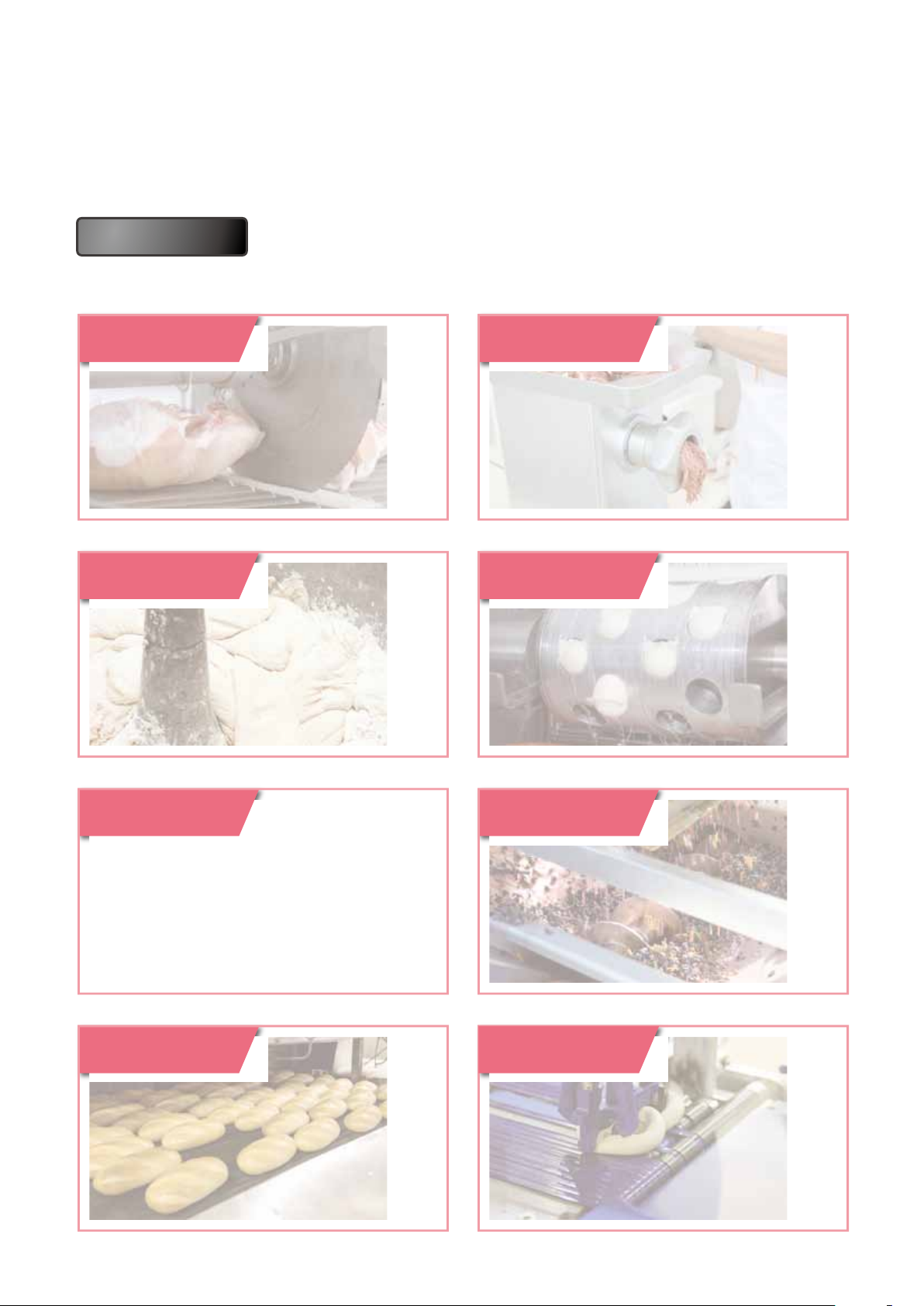
Applications
Ideal as a safety measure for use on machines that do not shut down immediately or
maintain high temperatures.
Cutting Grinding
Mixing Rotating
Packing
Squeezing
Baking Pressing
3
Safety Switch
and performance.
t interlock switches with solenoid.
Interlock Switch
IDEC ensures reliability
2-Contact
4-Contact
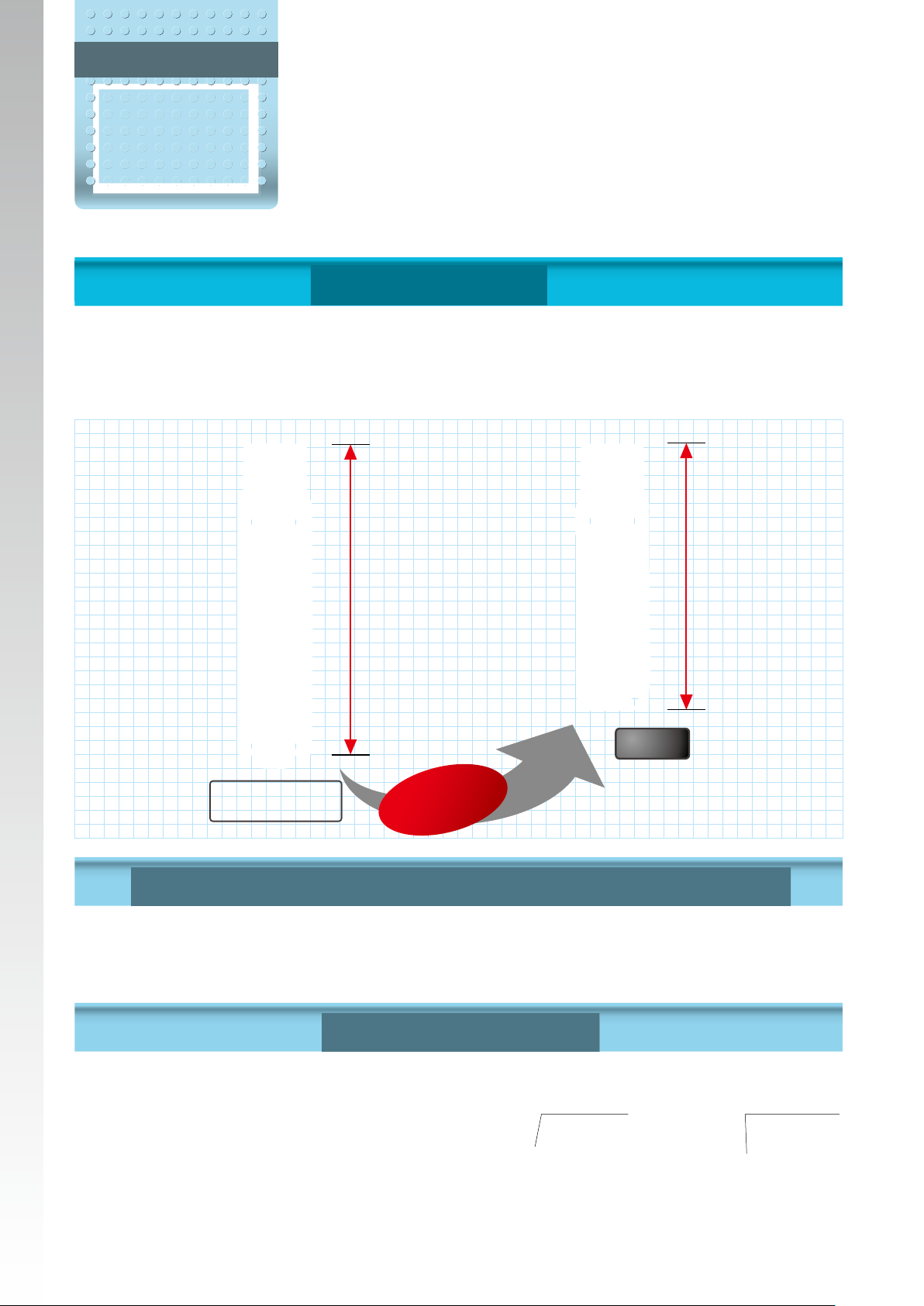
Size is reduced by 13% from conventional models.
Mounts on small doors and aluminum frames of machines.
Compact design with 2- and 4-contacts reduce installation space.
Greater exibility in machine design.
2-contact and 4-contac
Compact and slim!
127
145.7
HS5L
Conventional Model
HS5E
13%
Approx.
(Compared with IDEC products)
shorter
All dimensions in mm.
Compact design with powerful 1400N locking strength
The size is greatly reduced while achieving the same 1400N (Fzh) locking
strength as the conventional HS5E series. (GS-ET-19)
Rear unlocking button
Door lock can be unlocked inside the
barrier by a worker left inside a
hazardous area.
(Complies with escape release
dened in ISO14119 (2013) and
GS-ET-19)
Two types of unlocking buttons to suit
various applications.
4
Rear unlocking
button
Rear lock release
kit for frames
rformance.
th solenoid.
Spring clamp terminals
Spring clamp terminals offer excellent
vibration resistance, preventing wires
from loosening. No need for additional
tightening.
Driver port
Driver port
Wiring port
Wiring port
Energy saving!
Solenoid energy consumption: 200mA
Reduced by 25% from conventional
HS5E series.
266mA
Conventional Model
HS5E
Approx.
(Compared with IDEC products)
200mA
25%
HS5L
reduced
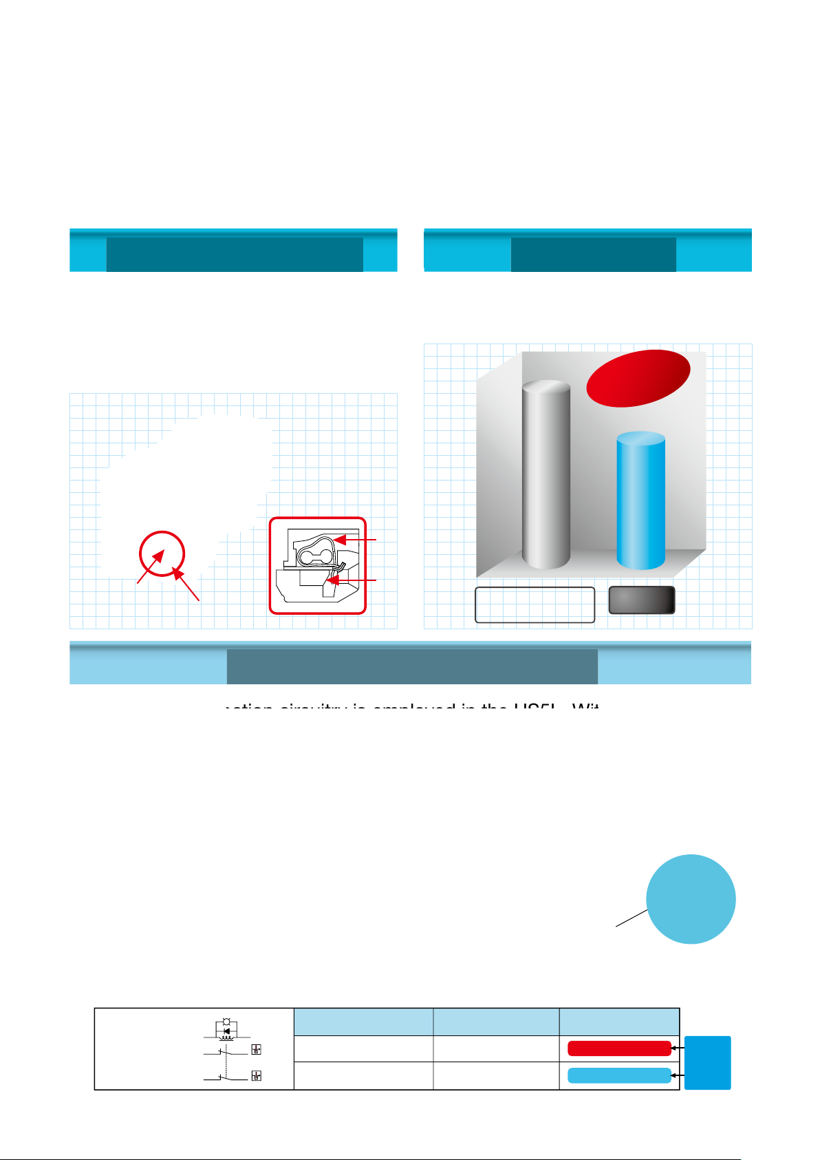
Head Removal Detection Circuitry
Head removal detection circuitry is employed in the HS5L. With this innovative
function, the monitor circuit (41-42) turns off when the head is removed from
the switch, such as when removing the head to change the head direction
(applicable with the HS5L spring lock models). For example, for circuit codes:
VB, VD and DD, which have two or more lock monitor circuits installed,
removing the head results in disparity (41-42: OFF, 51-52: ON).
This disparity is detected by the head removal detection function.
Head removal
detection function
Monitor circuit
(41-42)
● HS5L-VD44M-G (Lock monitor circuit)
(+)(−)
Lock monitor circuit
Lock monitor circuit
A2
41
A1
42
5251
Actuator
unlocked
Actuator unlocked Actuator locked Head removed
OFF ON
OFF ON
Actuator
locked
Head
removed
OFF
Disparity
ON
Note: Head removal detection function is not a direct opening action mechanism.
5
Safety Switch
Actuator
Wide variety of actuators for
interlock switches enhance
HS5 series
Actuators can be selected according to door
shapes and usage.
Actuator with rubber bushing ideal for use
•
on rattling doors.
Plug actuators ideal for use on heavily
•
rattling doors.
Movable actuators ideal for use
•
on hinged doors.
Sliding actuators for easy installation.
•
Actuators ideal for use on bouncing doors
•
also available.
exibility and usability!
Actuators can be selected according to door shapes and usage, and
can be installed exibly according to the installation site.
Wide variety of actuators
Angle Adjustable
(vertical) Actuator
Sliding Actuator
Right-angle Actuator
with rubber bushing
Right-angle Actuator
Straight Actuator
with rubber bushing
Straight Actuator
Spring Loaded
Actuator
Accessory exclusive
∗
for HS5L.
Plug Actuator
Padlock Hasp
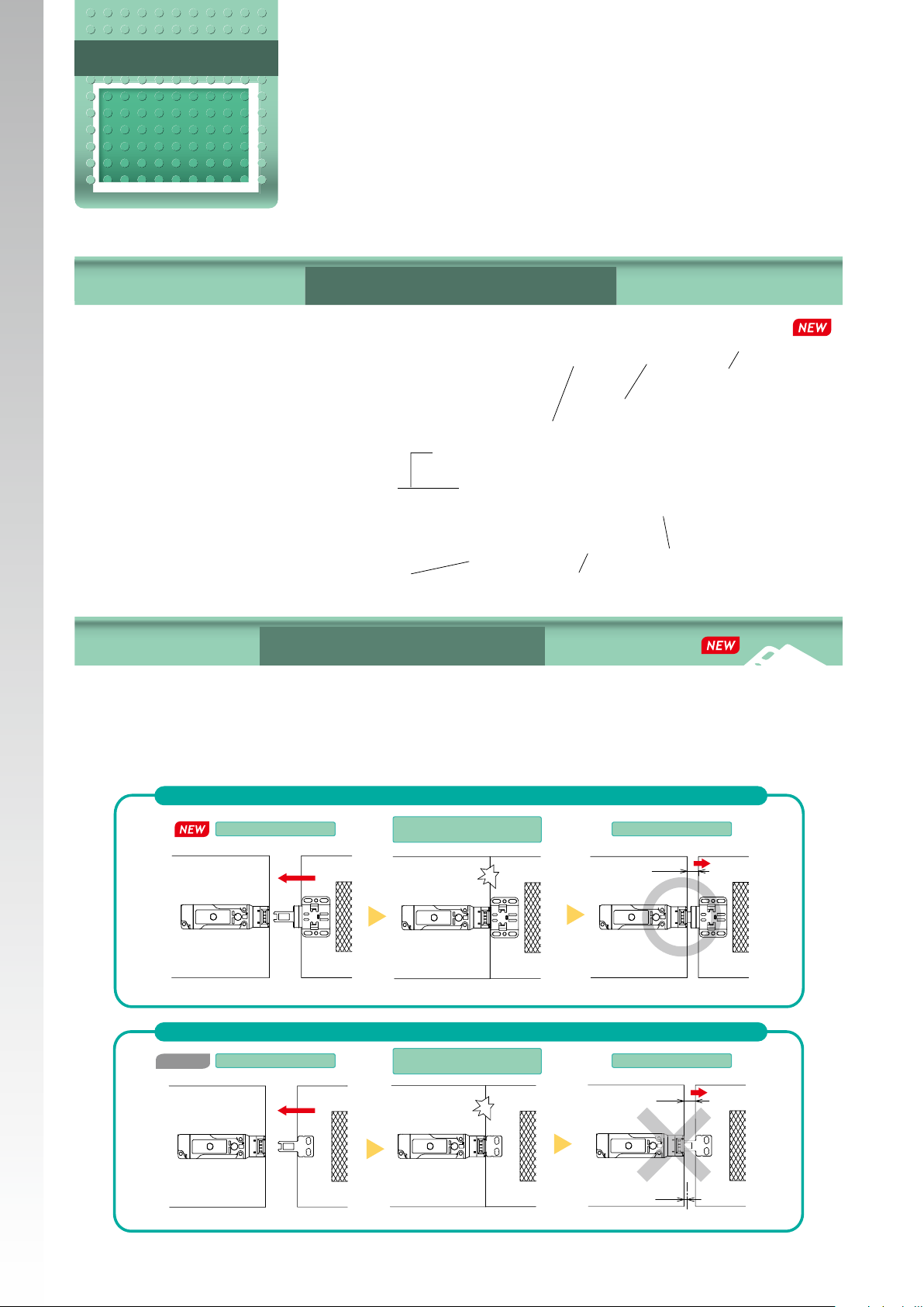
Spring loaded actuator
IDEC patented spring loaded actuator locks the door safely when
the door bounces. When the actuator is fully inserted (door closed
completely), the door can tolerate a space of up to 16mm.
∗
HS5L interlock switch and HS9Z-BA5 spring loaded actuator
Conventional
model
(1) Insert
HS5L interlock switch and HS9Z-A51A straight actuator
(1) Insert
(2) Fully inserted
(door completely shut)
(2) Fully inserted
(door completely shut)
The door can bounce open to up to 16mm.
Locking position
of HS9Z-A51A
The door can bounce open to up to 4.6mm.
Locking position
of HS9Z-A51A
(3) Door bounces
16
Lock
(3) Door bounces
16
Patent acquired
Accessory exclusive for HS5L.
4.6
Does not lock
6
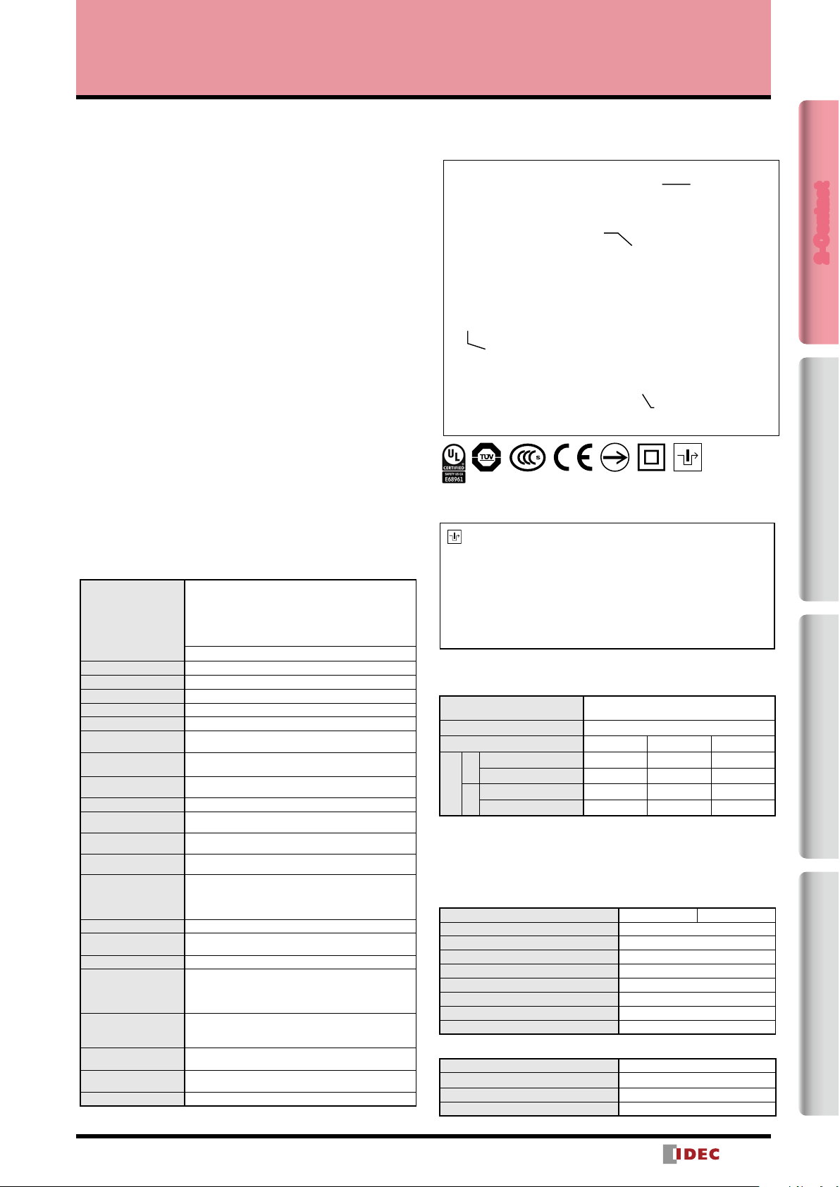
HS5L Interlock Switches with Solenoid (2-Contact)
Two-contact solenoid interlock switches ideal for use on applications such as food
machines and injection molding machines.
• Compact body: 35 × 40 × 127mm
• The locking strength is 1400N minimum.
• Spring clamp terminal block prevents loosening of wires due
to vibration.
• Gold-plated contacts suitable for small loads.
• Spring lock models (unlocks when the solenoid is energized)
and solenoid lock models (locks when solenoid is energized)
are available.
• The head orientation can be rotated, allowing 8 different
actuator entries.
• Actuators can be used with other HS5 series interlock
switches. Spring loaded actuator exclusive for HS5L available.
• LED indicator shows solenoid operation.
Spring Lock
• Automatically locks the actuator without power applied to the
solenoid.
• After the machine stops, unlocking is completed by the
solenoid, providing high safety features.
• Manual unlocking is possible in the event of power failure or
maintenance using a manual unlocking key.
• Head removal detection circuitry (spring lock models only).
Solenoid Lock
• The actuator is locked when energized.
• The actuator is unlocked when de-energized.
• Flexible locking function can be achieved, for an application
where locking is not required and sudden stopping of a
machine must be prevented.
Specifications
EN ISO14119
GS-ET-19 (TÜV approval)
EN60947-5-1 (TÜV approval)
Applicable Standards
Type and Coded level Type 2 low level coded interlocking device (ISO14119)
Operating Temperature –25 to + 55°C (no freezing)
Relative Humidity 20 to 95% (no condensation)
Storage Temperature –40 to +80°C (no freezing)
Pollution Degree 3
Impulse Withstand
Voltage
Insulation Resistance
(500V DC megger)
Electric Shock
Protection
Degree of Protection IP67 (IEC60529) Type 4X Indoor Use Only
Shock Resistance
Vibration Resistance
Actuator Operating
Speed
Direct Opening Travel
Direct Opening Force 120N min.
Actuator Retention
Force (Note)
Operating Frequency 900 operations per hour
Mechanical Durability
Electrical Durability
Conditional Shortcircuit Current
Cable
Weight (Approx.) 300g
Note: See page
UL508 (UL Listing)
CSA C22.2 No. 14 (c-UL listed)
GB14048.5 (CCC approval)
IEC60204-1/EN60204-1 (Applicable standards for use)
2.5kV
(between LED, solenoid and grounding: 0.5kV)
Between live and dead metal parts: 100MΩ min.
Between terminals of different poles: 100MΩ min.
Class II (IEC61140)
Operating extremes: 100m/s2 (10G),
Damage limits: 1000m/s2 (100G)
Operating extremes: 10 to 55Hz, amplitude 0.35 min.
Damage limits: 30Hz, amplitude 1.5mm min.
0.05 to 1.0m/s
11.0mm min. (Actuator: HS9Z-A51/A5P)
12.0mm min. (Actuator: HS9Z-A52/A51A/A52A/A53/
55/SH5/SH5L)
24.5mm min. (Actuator: HS9Z-BA5)
Fzh = 1400N min. (GS-ET-19)
However, Fzh=500N min. when HS9Z-A55 is used
2,000,000 times min.
(Operation frequency 900 times/hour, actuator insert/
remove, solenoid operation) 100,000 times min. when
HS9Z-SH5/SH5L (actuator insert/remove)
100,000 times min. (Operating Frequency: 900
operations per hour)
2,000,000 times min. (24V AC/DC, 100mA)
50A (250V) (Use 250V/10A fast-blow fuse for shortcircuit protection.)
0.3mm2 min. and 1.5mm2 max. or AWG22 min. to
AWG16 max. strand wire or single wire
16
regarding actuator retention force.
Straight Actuator
Straight Actuator with
Rubber Bushings
Angle Adjustable
(Vertical) Actuator
Right-angle Actuator
•Korean S Mark approval application pending
Marking for Locking Monitoring
The marking for lock monitoring described in clause 9.2.1
of ISO14119 can be used by satisfying the requirements in
general requirements (5.7.1), locking monitoring (5.7.2.2), and
ISO13849-1 (safety-related parts of control systems). This
marking has been added to the 2013 edition of ISO14119.
However, this marking cannot be applied to solenoid lock
switches according to general requirement (5.7.1).
Ratings
Contact Ratings
Rated Insulation Voltage (Ui)
Rated Current (Ith) 2.5A
Rated Voltage (Ue) *
Resistive Load (AC-12) − 2.5A 1.5A
AC
Inductive Load (AC-15) −
(Ie)*
Resistive Load (DC-12) 2.5A 1.1A 0.55A
DC
Inductive Load (DC-13) 2.3A 0.55A 0.27A
Rated Current
•Minimum applicable load (reference): 3V AC/DC, 5mA
(Applicable range may vary with operating conditions and load types.)
*UL, c-UL rating: Pilot Duty AC 0.75A/250V,
Pilot Duty DC 1.0A/30V
TÜV rating: AC-15 0.75A/250V, DC-13 2.3A/30V
CCC rating: AC-15 0.75A/250V, DC-13 2.3A/30V
Solenoid
Locking Mechanism Spring Lock Solenoid Lock
Rated Voltage 100% duty cycle 24V DC
Rated Current 200mA (initial value)
Coil Resistance 120Ω (at 20°C)
Pickup Voltage Rated voltage × 85% max. (at 20°C)
Dropout Voltage Rated voltage × 10% min. (at 20°C)
Maximum Continuous Applicable Voltage Rated voltage × 110%
Maximum Continuous Applicable Time Continuous
Insulation Class Class F
Indicator
Rated Voltage 24V DC
Rated Current 10mA
Light Source LED
Illumination Color G (Green)
250V
(between LED, solenoid and grounding: 30V)
30V 125V 250V
1.5A
0.75A
2-Contact4-ContactActuatorDimensions / Instructions
7
)
(−)(+)
(−)(+)
(−)(+)
Door Monitor
Lock Monitor
)
HS5L Interlock Switches with Solenoid (2-Contact)
0
(Actuator Mounting Reference Position)
HS5L Interlock Switches with Solenoid (2-Contact)
2-Contact Package Quantity: 1
Circuit
Code
Door Monitor
(Actuator inserted)
XD
2-Contact4-ContactActuatorDimensions / Instructions
Door Monitor Circuit: 1NC
Monitor Circuit:
Monitor Circuit:
Door Monitor Circuit: 2NC
XF M20 — HS5L-XF7Y4M-G
Monitor Circuit:
Monitor Circuit:
Door Monitor Circuit: 1NC,1NO
XG M20 — HS5L-XG7Y4M-G
Monitor Circuit:
Monitor Circuit:
XH
Monitor Circuit:
Monitor Circuit:
Contact Conguration Gland Port Size
Lock Monitor
Spring lock→Solenoid OFF
Solenoid lock→Solenoid ON
A2 A1
Lock Monitor Circuit: 1NC
1211
(Note)
4241
1211
21 22
1211
2423
Lock Monitor Circuit: 2NC
(Note)
4241
5251
(Note)
M20
M20
Note: This marking cannot be applied to solenoid locks according to general requirement (5.7.1) in ISO14119.
• The contact conguration shows the status when the actuator is inserted and the switch is locked.
• Actuators are not supplied with the interlock switch and must be ordered separately.
Spring lock Solenoid
Part No. Part No.
HS5L-XD44M-G HS5L-XD7Y4M-G
HS5L-XH44M-G HS5L-XH7Y4M-G
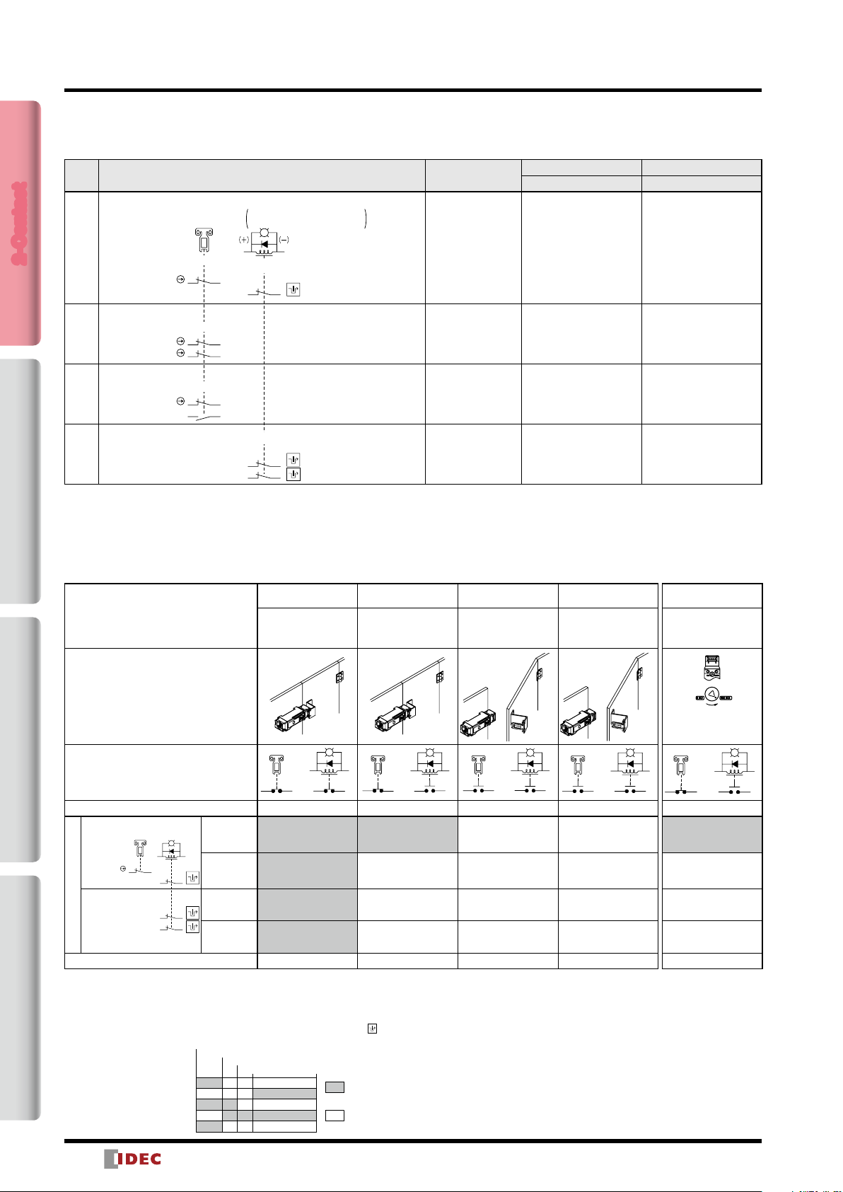
Circuit Diagrams and Operating Characteristics
Spring Lock
Status 1 Status 2 Status 3 Status 4
Interlock Switch Status
Door Closed
Machine ready to
operate
Solenoid de-energized
Door Status
(+)
Circuit Example: HS5L-XD4
A2
11 12 4241
Door Closed (locked) Closed (unlocked) Open Open
(Actuator inserted)
HS5L-XD4
Monitor Circuit:
Monitor Circuit:
(Solenoid OFF)
A2 A1
1211
HS5L-XH4
Monitor Circuit:
Monitor Circuit:
Part No. Circuit Diagram
Solenoid Power A1-A2 (common to all types) OFF (de-energized) ON (energized) ON (energized) OFF (de-energized)
(−)(+)
4241
4241
5251
Monitor Circuit
(door closed)
11-12
Monitor Circuit
(locked)
41-42
Monitor Circuit
(locked)
41-42
Monitor Circuit
(locked)
51-52
• The contact conguration shows the status when the actuator is inserted and the
switch is locked.
• Monitor Circuit: Sends monitoring signals of protective door open/closed status
(door monitor) or protective door lock/unlock status (lock monitor).
• For safety circuit input, connect to the monitor circuit with marking.
Approx. 3.3 (Locked position)
Main Circuit
Door Monitor Circuit (door open, NO)
Door Monitor Circuit (door closed, NC)
Lock Monitor Circuit (unlocked, NO)
Lock Monitor Circuit (locked, NC)
Approx. 5.3
Approx. 6.9
Approx. 26.4
Door Closed
Machine cannot be
operated
Solenoid energized
(−
A1
11 12 4241
(Stroke: mm)
: Contacts ON
(closed)
: Contacts OFF
(open)
Door open
Machine cannot be
operated
Solenoid energized
A2
A1
A2
A1
424111 12
Note: Actuator can be unlocked manually for
conrming the door movement before wiring
and energizing, and also for emergency
situation such as power failure.
• The operation characteristics shown in the chart are for HS9Z-A51.
For other actuators, add 1.3mm.
• See page 21 for HS9Z-BA5.
• The operation characteristics show the contact status when the
actuator enters the entry port of an interlock switch.
Door open
Machine cannot be
operated
Solenoid de-energized
A2
424111 12
When unlocking
manually
Door Closed
Machine cannot be
operated
Solenoid de-energized
Turn the manual
unlock key
(Note)
A1
(+)
11 12 4241
Closed (unlocked)
OFF (de-energized)
A2
(−
A1
8

HS5L Interlock Switches with Solenoid (2-Contact)
)
)
)
)
)
Circuit Diagrams and Operating Characteristics
Solenoid Lock
Status 1 Status 2 Status 3 Status 4
Interlock Switch Status
Door Closed
Machine ready to
operate
Solenoid energized
Door Closed
Machine cannot be
operated
Solenoid de-energized
Door open
Machine cannot be
operated
Solenoid de-energized
Door open
Machine cannot be
operated
Solenoid energized
Unlocking using
Manual Unlock Key
Door Closed
Machine cannot be operated
Solenoid de-energized
energized
➝
Door Status
(−
Circuit Example: HS5L-XD7Y
(+)
A2
11 12 4241
(−
A1
11 12 4241
(+)
A2
(−
A1
(+)
A2
(+)
A1
424111 12
A2
424111 12
Door Closed (locked) Closed (unlocked) Open Open
4241
4241
5251
Monitor Circuit
(door closed)
11-12
Monitor Circuit
(locked)
41-42
Monitor Circuit
(door closed)
11-12
Monitor Circuit
(door closed)
21-22
Monitor Circuit
(door closed)
11-12
Monitor Circuit
(door open)
23-24
Monitor Circuit
(locked)
41-42
Monitor Circuit
(locked)
51-52
ON (energized)
(Note 2)
Door Monitor
HS5L-XD7Y
Monitor Circuit:
Monitor Circuit:
(Actuator
inserted)
Lock Monitor
(Solenoid ON)
A2 A1
1211
HS5L-XF7Y (Note 3)
Monitor Circuit:
Monitor Circuit:
21 22
1211
HS5L-XG7Y (Note 3)
Monitor Circuit:
Monitor Circuit:
1211
2423
Part No. and Circuit Diagram
HS5L-XH7Y
Monitor Circuit:
Monitor Circuit:
Solenoid Power A1-A2 (all models) OFF (energized) OFF (de-energized) OFF (de-energized)
Note 1: Do not unlock manually while the solenoid is energized.
Note 2: Do not energize the solenoid for a long period of time while the door is open or while the door is unlocked
manually.
Note 3: Circuit codes XF and XG do not have signals to notify whether the switch is locked or unlocked. A different
method should be used to check the lock status.
• The contact conguration shows the status when the actuator is inserted and the switch is locked.
• Monitor Circuit: Sends monitoring signals of protective door open/closed status (door monitor) or protective door
lock/unlock status (lock monitor).
(−
A1
11 12 4241
Closed (unlocked)
(Note 1) (Note 2)
OFF (de-energized)
ON (energized)
➝
UNLOCKLOCK
When unlocking
manually
(+)
A2
(−
A1
2-Contact4-ContactActuatorDimensions / Instructions
Operation Characteristics (Reference)
0
(Actuator Mounting Reference Position)
Approx. 3.3 (Locked position)
Approx. 5.3
Approx. 6.9
Main Circuit
Door Monitor Circuit (door open, NO)
Door Monitor Circuit (door closed, NC)
Lock Monitor Circuit (unlocked, NO)
Lock Monitor Circuit (locked, NC)
• The operation characteristics shown in the chart above are for HS9Z-A51. For other actuators, add 1.3mm.
• See page 21 for HS9Z-BA5.
• The operation characteristics show the contact status when the actuator enters the entry port of an interlock switch.
Approx. 26.4
(Stroke: mm)
: Contacts ON
(closed)
: Contacts OFF
(open)
9

HS5L Interlock Switch with Solenoid (4-Contact)
Four-contact solenoid interlock switches ideal for use on limited mounting spaces
such as small doors.
• Compact body: 35 × 40 × 127mm
• The locking strength is 1400N.
• Spring clamp terminal block prevents loosening of wires due
to vibration.
• A variety of circuits. Dual safety circuit and four-circuit
independent outputs available.
2-Contact4-ContactActuatorDimensions / Instructions
• Gold-plated contacts suitable for small loads.
• Spring lock models (unlocks when the solenoid is energized)
and solenoid lock models (locks when solenoid is energized)
are available.
• The head orientation can be rotated, allowing 8 different
actuator entries.
• Actuators can be used with other HS5 series interlock
switches. Spring loaded actuator exclusive for HS5L available.
• LED indicator shows solenoid operation.
Spring Lock
• Automatically locks the actuator without power applied to the
solenoid.
• After the machine stops, unlocking is completed by the
solenoid, providing high safety features.
• Manual unlocking is possible in the event of power failure or
maintenance using a manual unlocking key.
• Head removal detection circuitry (spring lock models only).
Solenoid Lock
• The actuator is locked when energized.
• The actuator is unlocked when de-energized.
• Flexible locking function can be achieved, for an application
where locking is not required and sudden stopping of a
machine must be prevented.
Specifications
EN ISO14119, GS-ET-19 (TÜV approval),
Applicable Standards
Type and Coded Level Type 2 low level coded interlocking device (ISO14119)
Operating Temperature –25 to + 55°C (no freezing)
Relative Humidity 20 to 95% (no condensation)
Storage Temperature –40 to +80°C (no freezing)
Pollution Degree 3
Impulse Withstand
Insulation Resistance
(500V DC megger)
Electric Shock Protection Class II (IEC61140)
Degree of Protection IP67 (IEC60529) Type 4X Indoor Use Only
Shock Resistance
Vibration Resistance
Actuator Operating Speed 0.05
Direct Opening Travel
Direct Opening Force 120N min.
Actuator Retention Force
(Note)
Operating Frequency 900 operations per hour
Rear Unlocking Button
Mechanical Durability
Mechanical Durability
Electrical Durability
Conditional Short-circuit
Current
Cable
Weight (Approx.) 300g
Note: See page 16 regarding actuator retention force.
EN60947-5-1 (TÜV approval), UL508 (UL Listing
CSA C22.2 No.14 (c-UL listed), GB14048.5
IEC60204-1/EN60204-1 (Applicable standards for use)
Voltage
2.5kV (between LED, solenoid and grounding: 0.5kV)
Between live and dead metal parts: 100MΩ min.
Between terminals of different poles: 100MΩ min.
Operating extremes: 100m/s
2
(100G)
1000m/s
Operating extremes: 10 to 55Hz, amplitude 0.35 min.
Damage limits: 30Hz, amplitude 1.5mm min.
to
1.0m/s
11.0mm min. (Actuator: HS9Z-A51/A5P)
12.0mm min. (Actuator: HS9Z-A52/A51A/A52A/A53/
A55/SH5/SH5L)
24.5mm min. (Actuator: HS9Z-BA5)
Fzh = 1400N min. (GS-ET-19)
However, Fzh=500N min. when HS9Z-A55 is used
3,000 times min. (HS5L-L)
2,000,000 times min.
(Operation frequency 900 times/hour, actuator insert/
remove, solenoid operation) 100,000 times min. when
HS9Z-SH5/SH5L (actuator insert/remove)
100,000 times min.
(Operating Frequency: 900 operations per hour)
2,000,000 times min. (24V AC/DC, 100mA)
50A (250V) (Use 250V/10A fast-blow fuse for shortcircuit protection.)
2
min. and 1.5mm2 max. or AWG22 min. to
0.3mm
AWG16 max. strand wire or single wire
),
(CCC approval)
2
(10G), Damage limits:
Straight Actuator with
Rubber Bushings
Marking for Locking Monitoring
The marking for lock monitoring described in clause 9.2.1
of ISO14119 can be used by satisfying the requirements in
general requirements (5.7.1), locking monitoring (5.7.2.2), and
ISO13849-1 (safety-related parts of control systems). This
marking has been added to the 2013 edition of ISO14119.
However, this marking cannot be applied to solenoid lock
switches according to general requirement (5.7.1).
Ratings
Contact Ratings
Rated Insulation Voltage (Ui)
Rated Current (Ith) 2.5A
Rated Voltage (Ue)*
AC
(Ie)*
DC
Rated Current
•Minimum applicable load (reference): 3V AC/DC, 5mA
(Applicable range may vary with operating conditions and load types.)
*
UL, c-UL rating: Pilot Duty AC 0.75A/250V,
Pilot Duty DC 1.0A/30V
TÜV rating: AC-15 0.75A/250V, DC-13 2.3A/30V
CCC rating: AC-15 0.75A/250V, DC-13 2.3A/30V
Solenoid
Locking Mechanism Spring Lock Solenoid Lock
Rated Voltage 100% duty cycle 24V DC
Rated Current 200mA (initial value)
Coil Resistance 120Ω (at 20°C)
Pickup Voltage Rated voltage × 85% max. (at 20°C)
Dropout Voltage Rated voltage × 10% min. (at 20°C)
Maximum Continuous Applicable Voltage Rated voltage × 110%
Maximum Continuous Applicable Time Continuous
Insulation Class Class F
Indicator
Rated Voltage 24V DC
Rated Current 10mA
Light Source LED
Illumination Color G (Green)
Straight Actuator
Right-angle
Actuator
•Korean S Mark approval application pending
250V
(between LED, solenoid and grounding: 30V)
30V 125V 250V
Resistive Load (AC-12)
Inductive Load (AC-15) − 1.5A 0.75A
Resistive Load (DC-12)
Inductive Load (DC-13) 2.3A 0.55A 0.27A
− 2.5A 1.5A
2.5A 1.1A 0.55A
Adjustable actuator
(Bounce tolerant type)
10

3433
Monitor Circuit:
Lock Monitor
HS5L Interlock Switch with Solenoid (4-Contact)
HS5L Interlock Switches with Solenoid (4-Contact)
4-Contact (Spring Lock / Solenoid Lock) Package Quantity: 1
Circuit
Code
Contact Conguration Gland Port Size
Spring lock Solenoid
Part No. Part No.
VA
Door Monitor: 1NC,1NO
Monitor Circuit:
Monitor Circuit:
Monitor Circuit:
Door Monitor: NC,1NO
Monitor Circuit:
VB
Monitor Circuit:
Monitor Circuit:
Door Monitor: 2NC
Monitor Circuit:
VC
Monitor Circuit:
Monitor Circuit:
Door Monitor: 2NC
Monitor Circuit:
VD
Monitor Circuit:
Monitor Circuit:
Door Monitor: 3NC
Monitor Circuit:
VF
Monitor Circuit:
Monitor Circuit:
Door Monitor
(Actuator inserted)
12
231124
1211
23 24
12
211122
11 12
2221
1211
2221
31 32
Spring lock→Solenoid OFF
Solenoid lock→Solenoid ON
A2 A1
Lock Monitor Circuit: 1NC,1NO
41 42
53 54
Lock Monitor Circuit: 2NC
41
Lock Monitor Circuit: 1NC,1NO
41 42
53 54
Lock Monitor Circuit: 2NC
Lock Monitor Circuit: 1NC
41 42
(Note)
42
(Note)
(Note)
5251
(Note)
4241
(Note)
5251
(Note)
(Note)
M20
M20 HS5L-VB44M-G HS5L-VB7Y4M-G
M20 HS5L-VC44M-G HS5L-VC7Y4M-G
M20 HS5L-VD44M-G HS5L-VD7Y4M-G
M20 HS5L-VF44M-G HS5L-VF7Y4M-G
HS5L-VA44M-G HS5L-VA7Y4M-G
2-Contact4-ContactActuatorDimensions / Instructions
Door Monitor: 2NC, 1NO
Monitor Circuit:
Monitor Circuit:
VG
11 12
2221
Lock Monitor Circuit: 1NC
4241
(Note)
M20
HS5L-VG44M-G HS5L-VG7Y4M-G
Note: This marking cannot be applied to solenoid locks interlock switches according to general requirement (5.7.1) in ISO14119.
• The contact conguration shows the status when the actuator is inserted and the switch is locked.
• Actuators are not supplied with the interlock switch and must be ordered separately.
• For safety circuit input, connect to the monitor circuit with marking.
11

Door Monitor
Lock Monitor
HS5L Interlock Switch with Solenoid (4-Contact)
4-Contact / Rear Unlocking Button (Spring Lock) Package Quantity: 1
Circuit
Code
Contact Conguration Gland Port Size
Spring lock
Part No.
(Actuator inserted)
VA
Door Monitor Circuit: 1NC,1NO Lock Monitor Circuit: 1NC,1NO
Monitor Circuit:
2-Contact4-ContactActuatorDimensions / Instructions
Door Monitor Circuit: 1NC,1NO Lock Monitor Circuit: 2NC
VB
Door Monitor Circuit: 2NC Lock Monitor Circuit: 1NC,1NO
VC
Door Monitor Circuit: 2NC Lock Monitor Circuit: 2NC
VD
Monitor Circuit:
Monitor Circuit:
Monitor Circuit:
Monitor Circuit:
Monitor Circuit:
Monitor Circuit:
Monitor Circuit:
Monitor Circuit:
Monitor Circuit:
Monitor Circuit:
Monitor Circuit:
231124
1211
23 24
211122
11 12
2221
(Solenoid OFF)
A2 A1
41 4212
53 54
42
41
5251
41 4212
53 54
4241
5251
M20
M20 HS5L-VB44LM-G
M20 HS5L-VC44LM-G
M20
HS5L-VA44LM-G
HS5L-VD44LM-G
• The contact conguration shows the status when the actuator is inserted and the switch is locked.
• Actuators are not supplied with the interlock switch and must be ordered separately.
4-Contact / Dual Safety Circuit (Spring Lock) Package Quantity: 1
Circuit
Code
Contact Conguration Gland Port Size
Door Monitor
(Actuator inserted)
Lock Monitor
(Solenoid OFF)
Spring lock
Part No.
DD
Main Circuit: 1NC+1NC
1NC+1NC
Main Circuit:
Main Circuit:
11 12 4241
21
A1A2
525122
M20 HS5L-DD44M-G
• The contact conguration shows the status when the actuator is inserted and the switch is locked.
• Actuators are not supplied with the interlock switch and must be ordered separately.
4-Contact / Dual Safety Circuit / Rear Unlocking Button (Spring Lock) Package Quantity: 1
Circuit
Code
DD
Main Circuit: 1NC+1NC
1NC+1NC
Main Circuit:
Main Circuit:
Contact Conguration Gland Port Size
Door Monitor
(Actuator inserted)
11 12 4241
21
Lock Monitor
(Solenoid OFF)
A1A2
525122
M20 HS5L-DD44LM-G
• The contact conguration shows the status when the actuator is inserted and the switch is locked.
• Actuators are not supplied with the interlock switch and must be ordered separately.
Spring lock
Part No.
12

HS5L Interlock Switch with Solenoid (4-Contact)
(−)
0
(Actuator Mounting Reference Position)
(−)
(−)
(−)
(−)
Circuit Diagrams and Operating Characteristics
4-Contact / Rear Unlocking Button (Spring Lock)
Status 1 Status 2 Status 3 Status 4
Interlock Switch Status
Door Closed
Machine ready to
operate
Solenoid de-energized
Door Closed
Machine cannot be
operated
Solenoid energized
Door open
Machine cannot be
operated
Solenoid energized
Door open
Machine cannot be
operated
Solenoid de-energized
When unlocking
manually
Door Closed
Machine cannot be
operated
Solenoid de-energized
Press
Door Status
11
23
12
24
(+)
A2
(+)
A2
A1
Circuit Example: HS5L-VA4
Door Closed (locked) Closed (unlocked) Open Open
HS5L-VA4
Door Monitor
(Actuator
inserted)
Lock Monitor
(Solenoid OFF)
A2
Monitor Circuit:
Monitor Circuit:
Monitor Circuit:
41
24
53
HS5L-VB4
Monitor Circuit:
Monitor Circuit:
Monitor Circuit:
122311
24
HS5L-VC4
Monitor Circuit:
Monitor Circuit:
Monitor Circuit:
122111
22
41 42
53 54
HS5L-VD4
Monitor Circuit:
11 12
Monitor Circuit:
Part No. and Circuit Diagram
Monitor Circuit:
2221
HS5L-VF4
Monitor Circuit:
Monitor Circuit:
Monitor Circuit:
31 32
1211
2221
41 42
HS5L-VG4
Monitor Circuit:
11 12
Monitor Circuit:
Monitor Circuit:
2221
3433
42122311
54
4241
5251
4241
5251
4241
A1
Monitor Circuit
(door closed)
Monitor Circuit
(door open)
Monitor Circuit
Monitor Circuit
(unlocked)
Monitor Circuit
(door closed)
Monitor Circuit
(door open)
Monitor Circuit
Monitor Circuit
Monitor Circuit
(door closed)
Monitor Circuit
(door closed)
Monitor Circuit
Monitor Circuit
(unlocked)
Monitor Circuit
(door closed)
Monitor Circuit
(door closed)
Monitor Circuit
Monitor Circuit
Monitor Circuit
(door closed)
Monitor Circuit
(door closed)
Monitor Circuit
(door closed)
Monitor Circuit
Monitor Circuit
(door closed)
Monitor Circuit
(door closed)
Monitor Circuit
(door open)
Monitor Circuit
(door locked)
11−12
23−24
(locked)
41−42
53−54
11−12
23−24
(locked)
41−42
(locked)
51−52
11−12
21−22
(locked)
41−42
53−54
11−12
21−22
(locked)
41−42
(locked)
51−52
11−12
21-22
31-32
(locked)
41-42
11−12
21-22
33-34
41-42
11
23
122441
53
42
54
11
23
12
24
(+)
A2
41
53
42
54
A1
11
23
(+)
A2
122441
53
A1
42
54
Solenoid Power A1-A2 (all models) OFF (de-energized) ON (energized) ON (energized) OFF (de-energized)
•The contact conguration shows the status when the actuator is inserted and the switch is locked.
•Monitor Circuit: Sends monitoring signals of protective door open/closed status (door monitor)
or protective door lock/unlock status (lock monitor).
•For safety circuit input, connect to the monitor circuit with
Operation Characterics
(Reference)
Main Circuit
Door Monitor Circuit (door open, NO)
Door Monitor Circuit (door closed, NC)
Lock Monitor Circuit (unlocked, NO)
Lock Monitor Circuit (locked, NC)
Approx. 3.3 (Locked position)
Approx. 5.3
Approx. 6.9
Approx. 26.4
marking.
(Stroke: mm)
: Contacts ON
(closed)
: Contacts OFF
(open)
•The operation characteristics shown in the chart above are for HS9Z-A51.
For other actuators, add 1.3mm.
•See page 21 for HS9Z-BA5.
•The operation characteristics show the contact status when the actuator
enters the entry port of an interlock switch.
Note 1: Actuator can be unlocked manually for conrming
the door movement before wiring and energizing,
and also for emergency situation such as power
failure.
Note 2: When the operator is conned in a hazardous zone,
the actuator can be unlocked manually by pressing
the rear unlocking button.
41
53
·Turn the
manual
unlock key
(Note 1)
A1
11
42
23
54
Closed (unlocked)
OFF (de-energized)
·Press the
unlocking
(+)
A2
122441
53
rear
button
(Note 2)
42
54
2-Contact4-ContactActuatorDimensions / Instructions
A1
13

HS5L Interlock Switch with Solenoid (4-Contact)
(−)
(−)
(−)
(−)
Door Monitor
Lock Monitor
(−)
Circuit Diagrams and Operating Characteristics
4-Contact (Solenoid Lock)
Status 1 Status 2 Status 3 Status 4
Interlock Switch Status
2-Contact4-ContactActuatorDimensions / Instructions
Door Status
Door Closed
Machine ready to
operate
Solenoid energized
Door Closed
Machine cannot be
operated
Solenoid de-energized
Door open
Machine cannot be
operated
Solenoid de-energized
Door open
Machine cannot be
operated
Solenoid energized
Unlocking using
Manual Unlock Key
Door Closed
Machine cannot be operated
Solenoid de-energized
energized
When unlocking
manually
➝
UNLOCKLOCK
Circuit Example: HS5L-VA7Y
Door
HS5L-VA7Y
(Actuator inserted)
Monitor Circuit:
Monitor Circuit:
Monitor Circuit:
HS5L-VB7Y
Monitor Circuit:
Monitor Circuit:
Monitor Circuit:
HS5L-VC7Y
Monitor Circuit:
Monitor Circuit:
Monitor Circuit:
HS5L-VD7Y
Monitor Circuit:
Monitor Circuit:
Part No. and Circuit Diagram
Monitor Circuit:
HS5L-VF7Y
Monitor Circuit:
Monitor Circuit:
Monitor Circuit:
HS5L-VG7Y
Monitor Circuit:
Monitor Circuit:
Monitor Circuit:
231124
12
231124
12
211122
11 12
2221
1211
2221
31 32
11 12
2221
3433
(Solenoid OFF)
(−)(+)
A2
41
4212
53
54
4241
5251
41 42
53 54
4241
5251
41 42
4241
A1
Monitor Circuit
(door closed)
11−12
Monitor Circuit
(door open)
23−24
Monitor Circuit
(locked)
41−42
Monitor Circuit
(unlocked)
53−54
Monitor Circuit
(door closed)
11−12
Monitor Circuit
(door open)
23−24
Monitor Circuit
(locked)
41−42
Monitor Circuit
(locked)
51−52
Monitor Circuit
(door closed)
11−12
Monitor Circuit
(door closed)
21−22
Monitor Circuit
(locked)
41−42
Monitor Circuit
(unlocked)
53−54
Monitor Circuit
(door closed)
11−12
Monitor Circuit
(door closed)
21−22
Monitor Circuit
(locked)
41−42
Monitor Circuit
(locked)
51−52
Monitor Circuit
(door closed)
11−12
Monitor Circuit
(door closed)
21-22
Monitor Circuit
(door closed)
31-32
Monitor Circuit
(locked)
41-42
Monitor Circuit
(door closed)
11−12
Monitor Circuit
(door closed)
21-22
Monitor Circuit
(door open)
33-34
Monitor Circuit
(locked)
41-42
(+)
A2
A1
11
122441
23
Closed (locked) Closed (unlocked) Open Open
53
42
54
11
23
12
24
(+)
A2
41
53
A1
42
54
Solenoid Power A1-A2 (all models) ON (energized) OFF (de-energized) OFF (de-energized)
•The contact conguration shows the status when the actuator is inserted and the switch is locked.
•Main Circuit: Connected to the control circuit of machine drive part, sending interlock signals of the protective door.
•Monitor Circuit: Sends monitoring signals of protective door open/closed status (door monitor) or protective door
lock/unlock status (lock monitor).
Operation Characterics
(Reference)
Main Circuit
Door Monitor Circuit (door open, NO)
Door Monitor Circuit (door closed, NC)
Lock Monitor Circuit (unlocked, NO)
Lock Monitor Circuit (locked, NC)
0
(Actuator Mounting Reference Position)
Approx. 3.3 (Locked position)
Approx. 5.3
Approx. 6.9
Approx. 26.4
(Stroke: mm)
: Contacts ON
(closed)
: Contacts OFF
(open)
•The operation characteristics shown in the chart above are for HS9Z-A51.
For other actuators, add 1.3mm.
•See page 21 for HS9Z-BA5.
•The operation characteristics show the contact status when the actuator
enters the entry port of an interlock switch.
14
11
23
(+)
A2
122441
53
A1
42
54
(+)
A1
A2
41
12
11
53
24
23
ON (energized)
(Note 2)
Note 1: Do not attempt manual unlocking
whenthe solenoid is energized.
Note 2: Do not energize the solenoid for a long
time while the door is open or when the
door is unlocked manually.
11
42
23
54
Closed (unlocked)
OFF (de-energized)
ON (energized)
(+)
A2
122441
53
(Note 1) (Note 2)
42
54
➝
A1

HS5L Interlock Switch with Solenoid (4-Contact)
)
)
)
)
)
Circuit Diagrams and Operating Characteristics
4-Contact / Dual Safety Circuit, 4-Contact / Dual Safety Circuit / Rear Unlocking Button (Spring Lock)
Status 1 Status 2 Status 3 Status 4
Interlock Switch Status
Door Closed
Machine ready to
operate
Solenoid de-energized
Door Closed
Machine cannot be
operated
Solenoid energized
Door open
Machine cannot be
operated
Solenoid energized
Door open
Machine cannot be
operated
Solenoid de-energized
Door Status
(−
Circuit Example: HS5L-DD4
Door
HS5L-DD44
Door Monitor
(Actuator inserted)
Main Circuit:
Main Circuit:
11 12 4241
21
Lock Monitor
(Solenoid OFF)
A1A2
525122
HS5L-DD44L
Main Circuit:
Main Circuit:
Part No. and Circuit Diagram
11 12 4241
21
525122
Solenoid Power A1-A2 (all model)
(+)
A2
A1
11 42
12 41
5122
Closed (locked) Closed (unlocked) Open Open
Main
Circuit
11−42
Main
Circuit
21−52
Main
Circuit
11−42
Main
Circuit
21−52
OFF (de-energized) ON (energized) ON (energized) OFF (de-energized)
11 12 4241
5221
(+)
A2
(−
A1
11 42
12 41
52512221
(+)
A2
(−
A1
5221
5122
(+)
A2
11 42
12 41
5122
Note 1: Actuator can be unlocked manually for conrming the door movement before wiring and energizing, and also for emergency
situation such as power failure.
Note 2: When the operator is conned in a hazardous zone, the actuator can be unlocked manually by pressing the rear unlocking button.
(Only for the type with rear unlocking button)
• The contact conguration shows the status when the actuator is inserted and the switch is locked.
• Main Circuit: Connected to the control circuit of machine drive part, sending interlock signals of the protective door.
• For safety circuit input, connect to the monitor circuit.
Unlocking using
Manual Unlock Key
Door Closed
Machine cannot be
operated
Solenoid de-energized
·Turn the
manual
unlock key
(Note 1)
(−
A1
11 42
5221
Closed (unlocked)
OFF (de-energized)
·Press the
unlocking
(Note 2)
(+)
A2
12 41
5122
Press
rear
button
(−
5221
2-Contact4-ContactActuatorDimensions / Instructions
A1
Operating Characteristics (Reference)
(Actuator insertion position)
0
Approx. 3.3 (Locked position)
Approx. 5.3
Approx. 6.9
Main Circuit
• The operation characteristics shown in the chart above are of the HS9Z-A51. For other actuators, add 1.3mm.
• See page 21 for HS9Z-BA5.
• The operation characteristics show the contact status when the actuator enters the entry slot of an interlock switch.
Approx. 26.4
(Stroke: mm)
: Contacts ON
(closed)
: Contacts OFF
(open)
15

30
7.1
9
2.1
30
Actuators for HS5 Series Interlock Switches
Actuator
Description Part No. Package Quantity Remarks
Straight HS9Z-A51 1
Straight with Rubber Bushings HS9Z-A51A 1
Right-angle HS9Z-A52 1
Right-angle with Rubber Bushings HS9Z-A52A 1
Angle Adjustable (vertical) HS9Z-A53 1
Angle Adjustable (vertical/horizontal) HS9Z-A55 1
2-Contact4-ContactActuatorDimensions / Instructions
Accessories
Description Ordering No. Part No. Package Quantity Remarks
Sliding Actuator (Note 1) (Note 2) HS9Z-SH5 HS9Z-SH5 1
Spring Loaded Actuator (Note 2) (Note 3) HS9Z-BA5 HS9Z-BA5 1 Weight: 70g
Plug Actuator HS9Z-A5P HS9Z-A5P 1
Padlock Hasp HS9Z-PH5 HS9Z-PH5 1
Jumper (Note 4) HS9Z-JP5L HS9Z-JP5LPN02 2
Note 1: For specication on sliding actuators, see separate catalog.
Note 2: Actuator retention force is Fzh=1400N.
Note 3: HS9Z-BA5 can only be used for HS5L interlock switches. Also, HS9Z-BA5 can be used only on slide doors. Do not use on hinge doors.
Note 4: HS9Z-BA5 can only be used for HS5L interlock switches.
Actuator Dimensions and Mounting Hole Layouts All dimensions in mm.
Straight (HS9Z-A51)
6.2
28
20
2.24-R
Note: Actuator Stop
(supplied with the actuator)
10
32.4
6.4
(6)
0.85.2
15
26
Actuator Mounting Hole Layout
(Straight, Right-angle)
2-M4 Screw
2
20
Straight with Rubber Bushings (HS9Z-A51A)
7. 3 43.8
2-ø4.3
12
(20)
Washer (supplied)
0.8
Rubber Bushing
When
mounted (5)
Actuator retention force is Fzh=1400N.
Actuator retention force is Fz=500N. When a retention force of
500N or more is required, use HS9Z-A53.
∗
15.3
2-ø10
2-ø9
0.8
Note: Actuator Stop
(supplied with
the actuator)
2
The mounting center distance is set to
12 mm at the factory. When a 20mm
distance is required, adjust the
distance by moving the rubber
bushing sideways.
∗
The actuator has exibility to the
15
direction indicated by the arrows.
Actuator Mounting Hole Layout
(Straight with Rubber Bushings)
(Right-angle with Rubber Bushings)
2-M4 Screw
Ver tical
Swing
∗
Mounting centers can be widened to
20mm by moving the Rubber
Bushings.
12
Right-angle (HS9Z-A52) Right-angle with Rubber Bushings (HS9Z-A52A)
When mounted (39.7)
33
2 7.27.2
28
0.84.5
Note: Actuator Stop
(supplied with the actuator)
Actuator Cover
15
2-ø4.4
2
20
1.6
Jumper (HS9Z-JP5L)
2
16
5
5.4
When
mounted
(11.2)
30
Rubber Bushing
When
mounted
(5)
15.8
8.5
2-ø9
0.8
Horizontal
15
Washer (supplied)
0.8
2
2-ø10
Note: Actuator Stop
(supplied with the actuator)
Swing
Vertical
Swing
12
(20)
2-ø4.3
∗ When the mounting center
distance is set to 12mm at the
factory, the actuator has exibility
both vertically and horizontally.
∗ When the mounting center
distance is set to 20mm, the
actuator swings vertically.
Adjust the distance by moving the
rubber bushings.

Orienting Insert
Interlock Switch
Actuators for HS5 Series Interlock Switches
Actuator Mounting Hole Layout
Note: Actuator Stop Film
49
Actuator Dimensions and Mounting Hole Layouts All dimensions in mm.
Angle Adjustable (vertical) (HS9Z-A53)
R3.2
18
Door Hinge
Side
20°
44
72
58
2-M6 Screw
(Angle Adjustable (vertical))
58
(supplied with the actuator)
5
20
29
Angle Adjustment
(M3 hexagon socket head bolt)
33 max.
12 (21)
1
Note: The actuator stop lm and actuator stop are supplied with the
actuator and used when adjusting the actuator position. Remove
after the actuator position is determined.
Angle Adjustable (vertical/horizontal) (HS9Z-A55)
(Horizontal Swing)
(Vertical Swing)
Orienting
Insert
15 7
Orienting
Insert
3
Note: Actuator Stop Film
(supplied with the actuator)
Angle Adjustment
(M3 hexagon socket head bolt)
Note: Actuator Stop Film
(supplied with the actuator)
20゚
18.5 29
0.8
Angle Adjustment
(M3 hexagon socket head bolt)
2
20゚
Actuator Mounting Hole Layout
(Angle Adjustable (vertical/horizontal))
2-M4 Screw
23
R2.1
(M4 Hole)
1
3.6
26
38
38
2-Contact4-ContactActuatorDimensions / Instructions
Horizontal / Vertical Actuator Orientation
Accessory Dimensions and Mounting Hole Layouts All dimensions in mm.
Spring Loaded Actuator (HS9Z-BA5)
3
Horizontal Swing Vertical Swing
Actuator Stop
HS9Z-A51
Actuator
2.5
7
±0.75
Mounting
Actuator (SUS)
tolerance range
Thickness: 2.5
11.3
0.8mm line
31
15
35.1
3.3mm line
Lock limit line
41
The orientation of actuator swing (horizontal/vertical) can be changed using the orienting insert (white
plastic) installed on the back of the actuator. Attach the orienting insert if necessary. (See left diagram)
Do not lose the orienting insert, otherwise the actuator will not operate properly.
Actuator Mounting Reference Position
Interlock Switch
Actuator Stop
As shown in the gure on the right, the mounting reference
position of the actuator when inserted in the interlock switch
is the position where the actuator stop placed on the actuator
lightly touches the side surface of the interlock switch.
Actuator Cover
HS9Z-A52
Actuator
Note: After mounting the actuator, remove the actuator stop from the
actuator.
Mounting Hole Layout
10 to 15
6-M5
Screw
range: ±1.0
Mounting tolerance
Fasten at least four parts (either
A or C, and B in the drawing on
the right) with mounting screws.
Always fasten B to prevent
movement during use.
10 to 15
47
HS5L Interlock Switch with Actuator
A
57
0.8
B
C
47
+2.5
0
86.5
20 to 22
∗ When the actuator is installed on the same plane
as the HS5L interlock switch, because the height
of the actuator will be 5mm lower than the
interlock switch, adjustment is required by the
customer.
36.2
(Mounting tolerance range: 0.8 )
5
Body (SUS)
23
15
7
40
Door Stop
Door Stop
7
58
47
∗5±0.5
(Height adjustment)
17

HS5L Interlock Switches with Solenoid
61.6
61.6
Interlock Switch Dimensions and Mounting Hole Layouts
HS5L-
4
When using Horizontal Mounting / Straight Actuator (HS9Z-A51)
5.2 6.2
2-Contact4-ContactActuatorDimensions / Instructions
42.2
R2.2
Manual Unlock
LED
(with Indicator)
-G (with Indicator)
30
29.2
11
10
1
20
35
3
HS5L-
When using Horizontal Mounting / Straight Actuator (HS9Z-A51)
11
5
36.2
9
44.5
127
86.5
40
34
20
Manual Unlocking Key (supplied)
3-M4 Screw
20 to 22
10 to 11
Mounting Hole Layout
3
915
(24)
18 6.5
(24.5)
42.2
86.5
Manual Unlock
LED
(with Indicator)
4
5.2 6.2
29.2
R2.2
-G (with Indicator)
30
11
36.2
9
44.5
127
86.5
10
1
20
35
3
40
34
20
Rear Unlocking Button (supplied)
All dimensions in mm.
11
5
Manual Unlocking Key (supplied)
3-M4 Screw
7.7
27
Mounting Hole Layout
(24)
ø14
10 to 11
3
915
18
(24.5)
20 to 22
9
86.5
6.5
Accessories
Description Part No. Package Quantity Remarks
HS9Z-FL53 1
Rear Unlocking Button Kit (Note)
HS9Z-FL55 1
Note: See table below when selecting rear unlocking button kit.
Part No.
HS9Z-FL53
HS9Z-FL54
HS9Z-FL55
HS5L
Interlock Switch
(sold separately)
HS5L Interlock Switch Rear Unlocking Button Kit
Panel Thickness * (X)
(When mounting HS5L-L directly)
ø10.4
< X ≤ 33
23
< X ≤ 43
33
< X ≤ 53
43
Hinge + Plate
(SUS)
Pin (SUS)
Button (PA66)
ø40
Button pressed
(unlocked)
Button released
Panel Thickness * (X) HS9Z-FL54 1
M5 Screw
40
3325.5
73
31.5
16
30
33
25.5
60.5
ø22 to 30
Rear Unlocking
Button Hole (Note)
Rear Unlocking Button Kit
Mounting Hole Layout
60.5
16 to 30
Panel Thickness (X): 23 to 53
Link Rod
(SUS)
Screw (Iron)
All dimensions in mm.
Note: With the mounting hole dimension, the rear unlocking button rod does not touch the hole even when the interlock switch moves sideways.
18

Safety Precautions
HS5L Interlock Switches with Solenoid
• In order to avoid electric shock or re, turn power off before
installation, removal, wiring, maintenance, or inspection of the
interlock switch.
• If relays are used in the circuit between the interlock switch
and the load, use only safety relays, since welded or sticking
contacts of standard relays may invalidate the functions of the
interlock switch. Perform a risk assessment and make a safety
circuit which satises the requirements of the safety category.
• Do not place a PLC in the circuit between the interlock switch
and the load. Safety security can be endangered in the event of
a malfunction of the PLC.
• Do not disassemble or modify the interlock switch, otherwise a
malfunction or an accident may occur.
• Do not install the actuator in a location where a human body may
come into contact. Otherwise injury may occur.
• Solenoid lock is locked when energized, and unlocked when
de-energized. When energization is interrupted due to wire
disconnection or other failures, the interlock switch may be
unlocked causing possible danger to the operators. Solenoid
lock must not be used in applications where locking is strictly
required for safety. Perform a risk assessment and determine
whether solenoid lock is appropriate.
• When changing the head orientation, disconnect the cable and
turn the manual unlock to the UNLOCK position in advance. If
Instructions
• Do not use the interlock switch as a door stop. Install a
mechanical door stop at the end of the door to protect the
interlock switch against excessive force.
• Do not apply excessive shock to the interlock switch when
opening or closing the door. A shock to the interlock switch
exceeding 1,000m/s
switch.
• Prevent foreign objects such as dust and liquids from
entering the interlock switch while connecting a conduit or
wiring.
• Plug the unused actuator entry slot using the slot plug
supplied with the interlock switch.
• Do not store the interlock switches in a dusty, humid, or
organic-gas atmosphere, or in an area subjected to direct
sunlight.
• Use proprietary actuators only. When other actuators are
used, the interlock switch may be damaged.
• The locking strength is rated at 1400N. Do not apply a load
higher than the rated value. When a higher load is expected,
provide an additional system consisting of another interlock
switch without lock (such as the HS5D interlock switch) or a
sensor to detect door opening and stop the machine.
• Regardless of door types, do not use the interlock switch
as a door lock. Install a separate lock using a latch or other
measures.
• While the solenoid is energized, the switch temperature
rises approximately 40°C above the ambient temperature (to
approximately 95°C while the ambient temperature is 55°C).
Do not touch to prevent burns. If cables come into contact
with the switch, use heat-resistant cables.
• Although the HS9Z-A51A/A52A actuators alleviate shock
when the actuator enters a slot in the interlock switch, make
sure that excessive shock is not applied. If the Rubber
Bushings become deformed or cracked, replace with new
ones.
2
may cause damage to the interlock
the head orientation is changed when the cable is connected
and the manual unlock is in the LOCK position, machines may
start to operate, causing danger to the operators.
• HS5L interlock switches are Type 2 low level coded
interlocking devices (ISO14119). According to ISO14119, the
following is required to minimize defeat when installing and
constructing systems:
1. Prevent dismantling or de-positioning of the elements of
the interlocking device by use of non-detachable xing (e.g.
welding, gluing, one-way screws, riveting). However, use of
non-detachable xing can be an inappropriate solution in
cases where a failure of the interlocking device during lifetime
of the machinery can be expected and a fast change is
necessary. In this case measures mentioned below, should be
used to provide the required level of risk reduction.
2. Apply at least one out of the four measures below.
➀ Mounting out of reach.
➁ Physical obstruction or shielding.
➂ Mounting in hidden position.
➃ Integration of defeat monitoring by means of status
monitoring/cyclic testing.
Mounting Examples
Refer to the following drawing for the installation. Mount the
interlock switch to a xed machine or guard, and actuator
on the hinged door. Do not mount both interlock switch and
actuator on the hinged doors. This may result in the actuator
being inserted at a wrong angle to the interlock switch,
resulting in malfunction.
Application of Sliding Doors
Door
HS9Z-A51
Actuator
HS5L
Interlock
Switch
Latch
Door Stop
Application of Hinged Doors
HS9Z-A52
Actuator
Interlock Switch
Door
HS5L
Latch
HS9Z-A51
Actuator
2-Contact4-ContactActuatorDimensions / Instructions
19

HS5L Interlock Switches with Solenoid
m
Instructions
Minimum Radius of Hinged Door
When using the interlock switch for a hinged door, refer to the
minimum radius of doors shown below. Especially for doors with
a small turning radius, use vertical/horizontal movable actuators
(HS9Z-A53/A55).
Note: Because deviation or dislocation of a hinged door may occur in actual
applications, make sure of the correct operation by installing the
2-Contact4-ContactActuatorDimensions / Instructions
actual machine rst before use.
HS9Z-A52 Actuator
When the center of the hinged door is used as the reference for
the interlock switch contact surface:
Minimum Radius
(35)
Interlock Switch
Mounting Hole
Minimum Radius
170mm
Door Hinge
190mm
Door Hinge
(36.2)
When the center of the hinged door is used as the reference for
the actuator mounting surface:
Minimum Radius
(40.3)
Interlock Switch
Mounting Hole
Minimum Radius
230mm
Door Hinge
260mm
Door Hinge
(41.5)
HS9Z-A52A Actuator (with Rubber Bushings)
When the center of the hinged door is used as the reference for
the interlock switch contact surface:
Centers 12mm: 120mm
Centers 20mm: 170mm
Minimum Radius
Door Hinge Door Hinge
(36.2)
When the center of the hinged door is used as the reference for
the actuator mounting surface:
Minimum Radius
140mm
(35)
Interlock Switch
Mounting Hole
(161)
(231)
(111)
When using the HS9Z-A53 Angle Adjustable (vertical)
Actuator
• When the center of the hinged door is used as the reference for
the interlock switch contact surface: 50mm
• When the center of the hinged door is used as the reference for
the actuator mounting surface: 80mm
• Angle adjustment screw recommeded tightening torque: 0.8N·m.
Minimum Radius
50mm
Door
Hinge
(36.2)
Interlock
Switch
Mounting
Hole
(38)
Minimum Radius
80mm
Door
Hinge
(56.5)
Interlock
Switch
Mounting
Hole
(68)
When using the HS9Z-A55 Angle Adjustable (vertical/
horizontal) Actuator
• When the center of the hinged door is used as the reference for
the interlock switch contact surface: 50mm
• When the center of the hinged door is used as the reference for
the actuator mounting surface: 70mm
• When the center of the hinged door is used as the reference for
the interlock switch contact surface:
Horizontal Swing
Minimum Radius
50mm
Door
Hinge
(36.2)
When the center of the hinged door is used as the reference for
the actuator mounting surface:
Minimum Radius
70mm
Door Hinge
(55.5)
Vertical Swing
Minimum
Radius
50mm
Minimum Radius
70mm
Door
Hinge
(36.2)
Interlock
Switch
Mounting
Hole
(38)
Vertical SwingHorizontal Swing
Door Hinge
(55.5)
Interlock
Switch
Mounting
Hole
(58)
Centers 12mm: 230mm
Centers 20mm: 310m
Minimum Radius
Door Hinge
(48.2)
Minimum Radius
260mm
Door Hinge
(47)
Interlock Switch
Mounting Hole
(231)
Actuator Angle Adjustment (vertical/horizontal)
• Using the angle adjustment screw, the actuator angle can
be adjusted (refer to the dimensional drawing on page 16).
Adjustable angle: 0 to 20°
• The larger the adjusted angle of the actuator, the smaller the
applicable radius of the door opening. After installing the
actuator, open the door. Then adjust the actuator so that its
edge can be inserted properly into the actuator entry slot of the
interlock switch.
• After adjusting the actuator angle, apply Loctite to the
adjustment screw so that the screw will not move.
20
Installing the Head
Do not use plastic and metallic heads of HS5D interlock switches
on the HS5L. Be sure to use HS5L metallic heads.
* The metal heads of the HS5D and HS5L look similar. When using
these interlock switches adjacently, ensure that the heads are
not interchanged.
HS5LHS5D
Metallic HeadMetallic HeadPlastic Head
Metal
Plastic
Color: Red
* The metal head can be distinguished easily by the color of the
plastic.
Color: Silver
Color:
Red∗
Color:
Black∗

A
Instructions
HS5L Interlock Switches with Solenoid
Rotating the Head
The head can be rotated by removing the four screws from the
corners of the head and reinstalling the head in the desired
orientation. However, when changing the mounting direction of the
head after wiring, turn the manual lock release to the “UNLOCK”
position using the enclosed manual lock release key rst. When
reinstalling the head, make sure that no foreign object enters
the interlock switch. Tighten the screws tightly, without leaving a
space between the head and body, otherwise the interlock switch
may malfunction.
(Recommended tightening torque: 0.9 to 1.1 N·m)
Factory SettingHead can be rotated
Head Removal Detection Function
• Solenoid locks interlock switches are not equipped with the head
removal detection function.
• The head removal detection function is available only on spring
lock interlock switches with circuits VB, VD, and DD having two
or more lock monitor circuits. Removing the head will result in
disparity (41-42: OFF, 51-52: ON). Note that this function cannot
be detected with other models.
• Only the lock monitor circuit 41-42 turns off (open) when the
head is removed, such as when the head is rotated. The other
monitor circuit 51-52 turns ON (close). Be sure to connect the
lock monitor circuit (41-42) to a safety circuit.
Spring Loaded Actuator
• When using the actuator, be careful of protruding ends.
• Regardless of door types, do not use the HS9Z-BA5 actuator as
a door lock or a door stop.
• When an operator enters the hazardous zone, take safety
measures such as using a HS9Z-PH5 padlock hasp so that the
operator is not trapped inside and the machine cannot start by
mistake.
• Use the actuator only on sliding
doors. Do not use on hinged doors.
• As shown in the gure on the right,
do not insert the sliding actuator from
below. The actuator may fall out due
to shocks.
• The HS9Z-BA5 actuator can only be
used for HS5L interlock switches. Do
not use the HS9Z-BA5 actuator for
other products.
• Do not modify or disassemble the
actuator.
Installation (when installation reference is 0.8mm)
• The actuator protrudes out when the actuator is not inserted
(door is open) as shown in 1. in the drawing.
• The mounting reference position can be set to 0.8mm when the
actuator is fully inserted and the actuator protrudes up to the
0.8mm line.
1. Removed
2. When fully inserted
(the door is completely shut)
A
3. Bounce (door gap)
Bounce tolerance
(Within the
lockable range)
· Drawing of interlock switch and HS9Z-BA5
when the actuator is fully inserted
(when the door is completely shut)
Mounting
reference
0.8mm
Interlock
switch
16mm
Detail view of A
Actuator
0.8mm line
Interlock switch
Align with the
0.8mm line
Interlock switch
Lock limit line
HS9Z-BA5
0.8mm line
Adjustment
Adjustment Procedure
1. Make a hole at A or C.
2. Fasten temporarily with screws, and check the actuator
position.
3. Make a hole at B and x the actuator using a screw or a rivet.
• 3.3mm line
The mounting reference position is where the door is fully closed,
and there is a 0.8mm space between the safety switch and
HS9Z-BA5, but can be adjusted up to the 3.3mm line.
The actuator is most securely locked when the mounting
reference position is at the 0.8mm line. However, adjust between
0.8 to 3.3mm if the safety switch is mounted on a door where the
space might become smaller.
• Lock limit line
When a door opens by bouncing, if the
lock limit line is outside of the edge of the
3.3mm line
0.8mm
line
interlock switch, the force of the bounce
may be too large so that the door may not
lock.
Safety Precautions
Lock limit
line
• The maximum gap of the door that can be locked is 16mm.
(When mounting reference is a the 0.8mm line)
• If the safety distance and minimum gap does not satisfy the
requirements of ISO13857, make the gap smaller by overlapping
the doors or by providing sufcient distance from the hazardous
source.
• The operating characteristics may change when the actuator is
used with the HS5L. Check the operating characteristics before
use.
Characteristic Diagram (Reference)
When the mounting reference is at the 0.8mm line:
Normal door
closing position
0
∗ Bounce can be tolerated to approximately 16mm.
Door close contact ON/
Door open contact OFF
Locking position
Approx. 10.1mm
Lockable range
Maximum gap 16mm
40.2mm
Insert
Approx. 20.4mm Door open contact ON
Approx. 18.4mm Door close contact OFF
Approx.16mm Locking position
Pull out
B
2-Contact4-ContactActuatorDimensions / Instructions
C
21

HS5L Interlock Switches with Solenoid
Screw
Instructions
[Reference] When using HS9Z-A51A with HS5L interlock switch:
Approx. 4.6mm Locking position
Approx. 6.6mm Door open contact ON
Approx. 8.2mm Door close contact OFF
0
Lockable range
Maximum gap
Approx. 4.6mm
2-Contact4-ContactActuatorDimensions / Instructions
∗ Approx. 4.6mm for HS9Z-A51A.
Approx. 8.2mm Door open contact ON
Approx. 6.6mm Door close contact OFF
Approx. 4.6mm Locking position
23.1mm
Insert
Pull out
Manual Unlocking
Spring lock
The spring lock interlock switch allows manual unlocking of the
actuator to precheck proper door movement before wiring or
turning power on, as well as for emergency use such as a power
failure.
Solenoid lock
The solenoid interlock switch does not unlock even when the
solenoid is de-energized. However, the interlock switch can be
unlocked manually in emergency cases.
UNLOCKLOCKUNLOCKLOCK
UNLOCK
LOCK
Normal Position
Manual Unlocking
Position
When locking or unlocking the interlock switch manually, turn the
key fully using the manual unlock key supplied with the interlock
switch. Using the interlock switch with the key not fully turned
(less than 90°) may cause damage to the interlock switch or
operation failures (when manually unlocked, the interlock switch
will keep the main circuit disconnected and the door unlocked).
Do not apply excessive force to the manual unlock, otherwise the
manual unlock will become damaged. Do not leave the manual
unlock key attached to the interlock switch during operation.
This is dangerous because the interlock switch can always be
unlocked while the machine is in operation.
Safety Precautions
Before manually unlocking the interlock switch, make sure that the
machine has come to a complete stop. Manual unlocking during
operation may unlock the interlock switch before the machine
stops, and the function of interlock switch with solenoid is lost.
Installing the Rear Unlocking Button
(HS5L-L)
After installing the interlock switch on the
panel, place the rear unlocking button
(supplied with the switch) on the push
rod on the back of the interlock switch,
and fasten the button using M3 sems
screw (supplied with the switch).
Push Rod
Rear Unlocking
Button
Mounting
Screw
(M3 sems)
HS5L-L
When installing on a mounting frame
thicker than 6mm, use the rear unlocking button kit HS9Z-FL5
(sold separately).
Safety Precautions
After installing the rear unlocking button, apply Loctite to the
screw so that the screw does not become loose. The rod is made
of SUS, the button is made of glass-reinforced PA66 (66 nylon)
and the screw is made of iron. Take the compatibility of the plastic
material and Loctite into consideration.
Installing the Rear
Push Rod
Unlocking Button Kit
1. Install the connecting rod onto the
push rod on the HS5L-L rear
unlocking button interlock switch.
2. A pin is attached to the connecting
rod. Insert the pin into the hole in
the push rod, using pliers.
Connecting
Rod
Panel
HS5L-L
Pin
Interlock Switch
3. Pull the connecting rod from the hole in the mounting frame,
and turn the button operating pin to the horizontal position.
Connecting
Rod
Pull
Connecting Rod Orientation
Correct
Incorrect
Safety Precautions
• Ensure that the connecting rod is pulled out completely and it is
horizontal to the interlock switch, otherwise the unlocking button
cannot be installed.
Note: Frame must be supplied by the user.
For the mounting hole layout of interlock switches, see
dimensions on page 18.
4. Install the unlocking button on the connecting rod by tting the
pin to the grooves on the back of the button, and fasten the
base plate on the mounting frame using the screws.
Button
Groove
(1) Pull up once
Unlocking
Button
Button
Operating
A
Pin
B
(2)
5. After fastening the screws, check if locking and unlocking
operations can be performed.
Safety Precautions
• Install the rear unlocking button
kit in the correct direction as
shown below. Do not install
the kit in incorrect directions,
otherwise malfunction may
occur.
• Do not apply strong force
Correct
orientation
Incorrect orientation
exceeding 100m/s2 to the
interlock switch while the rear unlocking button is not pressed,
otherwise malfunction may occur.
Unlocking the Manual Lock Using the
Rear Unlocking Button
Use the rear unlocking button when a worker is locked inside
a safety fence (hazard area). (Compliant with escape release
described in ISO14119 (2003) and GS-ET-19)
Unlock
Rear Unlocking Button
Procedure
• When the rear unlocking button is pressed, the interlock switch
is unlocked and the door can be opened.
• To lock the interlock switch, pull back the button.
• When the button remains pressed, the interlock switch cannot
be locked even if the door is closed, and the main circuit remains
open.
Safety Precautions
• Install the rear unlocking button in the place where only the
operator inside the hazardous area can use it. Do not install the
button in a place where an operator outside the hazardous area
can use it, otherwise the interlock switch can be unlocked during
usual machine operation, causing danger.
Unlock
Rear Unlocking
Button Kit
22

Instructions
Terminal wiring diagram
M4 Screw
8 to 9mm
ø2.5
HS5L Interlock Switches with Solenoid
• Operate the rear unlocking button by hand only. Do not operate
using a tool or with excessive force. Do not apply force to
the button from the direction other than the proper direction,
otherwise the button will be damaged.
Recommended Tightening Torque
• HS5L interlock switch: 1.8 to 2.2 N·m (four M4 screws)*
• Lid mounting screw: 0.5 to 0.7 N·m (M3 screw)
• Rear unlocking button: 0.5 to 0.7 N·m (M3 screw)
• Rear unlocking button kit: 4.8 to 5.2 N·m (M5 screw)
• Actuators
HS9Z-A51: 1.8 to 2.2 N·m (two M4 screws)*
HS9Z-A52: 0.8 to 1.2 N·m (two M4 flat head screws)
HS9Z-A51A/A52A: 1.0 to 1.5 N·m (two M4 screws)*
HS9Z-A53: 4.5 to 5.5 N·m (two M6 screws)*
HS9Z-A55: 1.0 to 1.5 N·m (two M4 screws)*
HS9Z-BA5: 4.5 to 5.5 N·m (two M5 screws/four)*
* If the mounting screw recommended tightening torque values
above is not satised, check loosening after installation
throughly.
• Mounting screws need to be prepared by the customer.
• To avoid unauthorized or unintended removal of the interlock
switch and the actuator, it is recommended that the interlock
switch and actuator are installed in a secure manner, for example
using special screws or welding the screws (ISO14119).
• When installing the HS9Z-A51A
and HS9Z-A52A actuators, use the
washer (supplied with the actuator)
on the hinged door, and mount
tightly using two M4 screws.
Mounting centers: 12mm (factory
setting), adjustable to 20mm
Note: Choose mounting
centers of either
12mm or 20mm.
Washer
(supplied)
Rubber
Bushing
Hinged Door
M4 Screw Hole
Applicable Cable Glands
Use a cable gland with IP67 protection degree.
Applicable Cable Gland Dimensions
M20
9mm max.
When Using Flexible Conduits (Example)
Flexible conduit example: VF-03 (Nihon Flex)
Conduit Port Size Plastic Cable Gland Metal Cable Gland
M20 — RLC-103EC20 (Nihon Flex)
When Using Multi-core Cables (Example)
Flexible conduit example: VF-03 (Nihon Flex)
Conduit Port Size Plastic Cable Gland Metal Cable Gland
M20
Different cable glands are used depending on the cable sheath
outside diameter. When purchasing a cable gland, conrm that the
cable gland is applicable to the cable sheath outside diameter.
* When using ST-M20X1.5, use with gasket below:
GPM20 (Manufacturer: LAPP Distributor: K.MECS)
ST-M20X1.5*
(Manufacturer: LAPP)
(Distributor: K-MECS)
max.
30mm
ALS-EC20
(Nihon Flex)
Lead-in Wire Length and Wiring Examples
Connector
Interlock switch
2-Contact
11/51
12/52
21/23/
41
A1A2
4-Contact
21/23
A2
22/24
1211 4241
8 to 9mm
31/33/
51/53
32/34/
52/54
A1
30 to 35
mm
Cautions for Wiring
Use the following applicable wiring.
Stranded wire or solid wire (1 wire):
0.3 to 1.5mm2 (AWG22 to AWG16)
Make sure to strip the wire insulation 8
to 9mm from the end. If the strip
length is too short, the wire may fall
out. If the strip length is too long, it
may short circuit with other wires.
Twist the wires and make sure that
there are no wire whiskers.
When using stranded wires without
ferrules, make sure that the core wires
have not been loosened.
• For wiring, use screwdrivers as
shown in the right. (The shape of the
tip of the screwdriver is in accordance with DIN5264)
• The inserting port of the wire and screwdriver, and direction of
the tip is as shown in the diagram below.
32/34/
11
22/24
12
31/33/
51/53
4241
52/54
A1
21/23
A2
• When using ferrules for stranded wires, use the ferrule listed in
the following table.
Compatible Wire Model No. Manufacturer
2
0.34mm
0.5mm
0.75mm
1mm
0.5mm
0.75mm
1mm
2
2
AWG22 AI0.34-6TQ
2
AWG20 AI0.5-6WH
2
AWG18 AI0.75-6GY
AWG18 AI1-6RD
2
AWG20 TE0.5-8
2
AWG18 TE0.75-8
AWG18 TE1.0-8
8 to 9mm
7º to 13
0.4
Screwdriver port
and direction of the
screwdriver tip.
Wire port
Phoenix Contact
NICHIFU
Co., Ltd.
2-Contact4-ContactActuatorDimensions / Instructions
22/24/
42
2.5
23
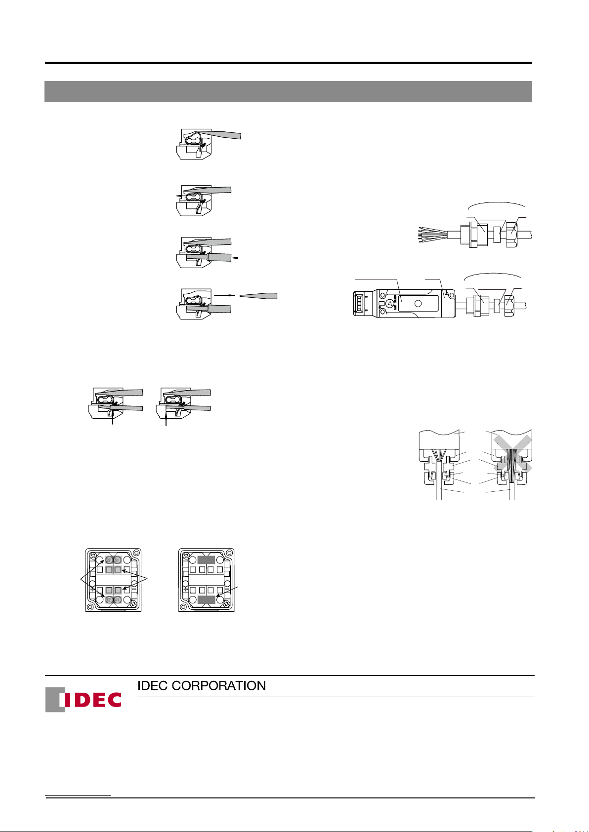
HS5L Interlock Switches with Solenoid
Specications and other descriptions in this catalog are subject to change without notice.
Cat. No. EP1534-0 JANUARY 2015 PDF
6-64, Nishi-Miyahara 2-Chome
, Yodogawa-ku, Osaka 532-0004, Japan
8 to 9mm
0.4
7º to 13
ø2.5
2.5
8 to 9mm
0.4
7º to 13
ø2.5
2.5
8 to 9mm
0.4
7º to 13
ø2.5
2.5
8 to 9mm
0.4
7º to 13
ø2.5
2.5
8 to 9mm
0.4
7º to 13
ø2.5
2.5
Instructions
Wire connection method
1. Insert the screwdriver into
the square-shaped port from
a slightly slanted angle as
shown, until the screw-driver
tip touches the bottom of the
spring. Make sure that the
direction of the blade edge is correct.
2. Push in the screwdriver until it
touches the bottom of the port.
The wire port is opened, and the
screwdriver is held in place.
The screwdriver will not come
off even if you release your hand.
3. While the screwdriver is retained
in the port, insert the wire or
ferrule into the round-shaped
wire port.
4. Pull out the screwdriver. The
connection is now complete.
Safety Precautions
When using wires with insulation diameter of ø2.0mm or less, do
not insert the wire too deeply where the insulation inserts into
the spring clamp opening. Make sure that the wire insulation is
stripped 8 to 9mm and the wire is inserted to the bottom.
Incorrect Correct
Insulation inserted
too deep
Wire inserted to
the bottom
If there is a need to insert the screwdriver while holding the
interlock switch with hands, be careful not to injure your ngers
with the tip of the screwdriver.
Connect one wire to one wiring port.
(According to IEC 60204 (JIS 9960-1) 13.1.1 General Requirement)
Installing the HS9Z-JP5L Jumper
HS9Z-JP5L is used on a 4-contact interlock switches to connect
the door monitor circuit (11-12) / (21-22) in series with the lock
monitor circuit (41-42)/(51-52) for safety circuit input.
For example, when wiring 12 and 41:
Insert the
jumper into
the wiring
port
1. As shown in the gure on the left above, insert a screwdriver in
A2
21 52
11 42
A1
Screwdriver
port
21 52
A2
11 42
the screwdriver ports.
2. Insert the jumper completely in wiring ports 12 and 41.
3. Pull out the screwdriver. The wiring of the jumper is complete.
A1
12-41
connected
using jumper
Safety Precautions
• For circuit code DD, a jumper is wired between 12-41 and 22-51
at factory setting.
• Be sure to connect only to 12-41 and 22-51.
Connector Wiring
Perform wiring according to following procedures 1. to 4.
1. Insert the cable into the connector. Leave A and B untightened.
2. Open the cover and insert the cable into the cover.
3 Wire to the terminals.
4 Tighten in the order of A → Cover → B.
Interlock switch Cover
* To remove the wiring, turn the power off and then unwire in the
order of B → cover (→waterproof gasket → A).
Note: When removing A, because the waterproong gasket is
tightly attached to the cable, pull out the gasket carefully
with tweezers so that the gasket is not damaged before
loosening A. Otherwise, the cable will rotate together with A
when loosened, and might break due to excessive twisting.
Also, when reassembling, place the gasket in the original
position rst.
Safety Precautions
• When opening the cover, be
careful not to lose the cover
mounting screw.
• When tightening connector
B, insert the cable into the
connector, and set it to a
position where the gasket
of the connector holds the
cable sheath, otherwise, its
waterproof performance might
be impaired.
• Tighten the connector in
order of A → B. If connector
B is tightened rst, the wiring
connected to the spring
clamp terminal may become twisted when tightening A, causing
disconnection or malfunction.
• Tighten the connectors with tightening torque according to the
torque value recommended by the connector manufacturer.
Otherwise, waterproof performance might be impaired.
• Do not exert excessive load, pressure, or tensile force on the
cable, otherwise, disconnection or malfunction might occur.
Spring clamp
terminal block
Gasket holds
the sheath
tightly
Make sure that the entire bore
surface of the gasket is in contact
with the sheath.
Connector (sold separately)
Connector (sold separately)
Interlock
Waterproong
packing
Waterproong
A
gasket
Waterproong
A
gasket
switch
Cover
A
B
Sheath
B
B
Spring clamp
terminal block
Sheath is
loose
24
 Loading...