

Page 1
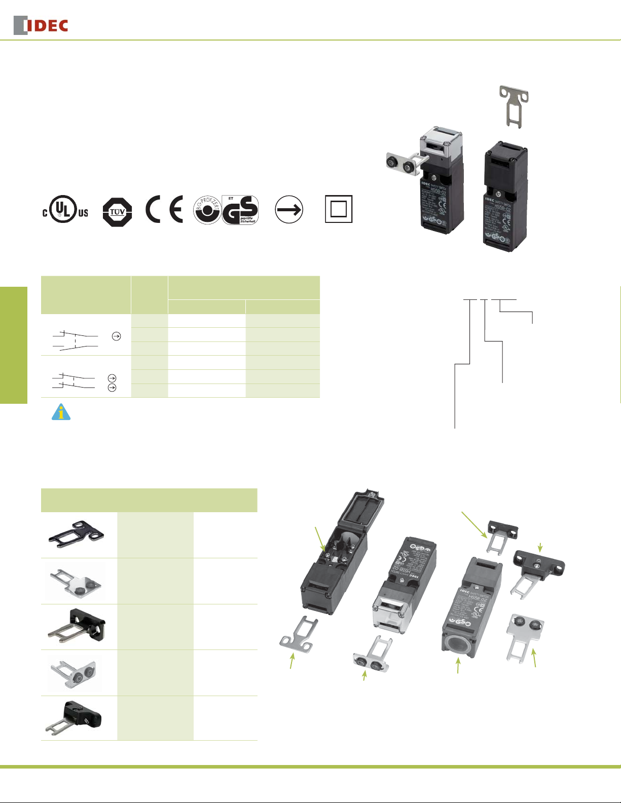
HS5B features:
30mm x 30mm x 91mm Compact Housing
•
Available with 2 Contact Confi gurations (1NO + 1NC or 2NC)
•
Flexible Installation: By turning the head of the switch to the desired angle, the actua-
•
OverviewX Series E-StopsDoor Interlock SwitchesEnabling SwitchesBarriersAS-Interface Safety at Work
tor can be accessed from 8 directions
Plastic Housing: Light weight
•
Direct Opening Action: Opening the door forces the contacts to disconnect even if the
•
contacts are welded (IEC60947-5-1)
Degree of Protection: IP67 (IEC60529)
•
HS5B Series
Door Interlock Switches
HS5B Series Miniature Interlock Switch
Contact Confi guration
1NC-1NO
3
2NC
3
Conduit
Port
Size
Zb
Zb
4
21
4
21
The actuators are not included, must be ordered separately.
G1/2 HS5B-11B HS5B-11ZB
PG13.5 HS5B-11NP —
M20 HS5B-11BM HS5B-11ZBM
G1/2 HS5B-02B HS5B-02ZB
PG13.5 HS5B-02NP —
M20 HS5B-02BM HS5B-02ZBM
Actuator Keys
Appearance Description
Straight HS9Z-A51
GS-ET-15
BG standard in Germany
Direct Opening
Action
Part Numbers
Part Number
(Standard Stock in bold)
Plastic Head Type Metal Head Type
Parts Description
Part Number
(Package Qty 1)
M3.5 Terminal
Screws
Double
Installation
Part Number Key
HS5B - 11 Z BM
Head Material
blank: Plastic
Z: Metal
Circuit Code
11: 1NO-1NC
02: 2NC
Right-angle Actuator
Head Housing Color/
Conduit Port
B: Black / G1/2
BM: Black /M20
NP: Gray PG13.5
Angle Adjustable
Actuator
(for hinged doors)
350
Straight w/rubber
bushings
Right-angle HS9Z-A52
Right-angle w/rubber
bushings
Angle Adjustable
(for hinged doors)
HS9Z-A51A
HS9Z-A52A
HS9Z-A55
Straight Actuator
www.idec.com
Right-angle Actuator
Actuator w/rubber bushing
Conduit Port
(Use conduits or cable glands
which can maintain IP67
protection.)
Straight Actuator
w/rubber bushing
Page 2
Door Interlock Switches
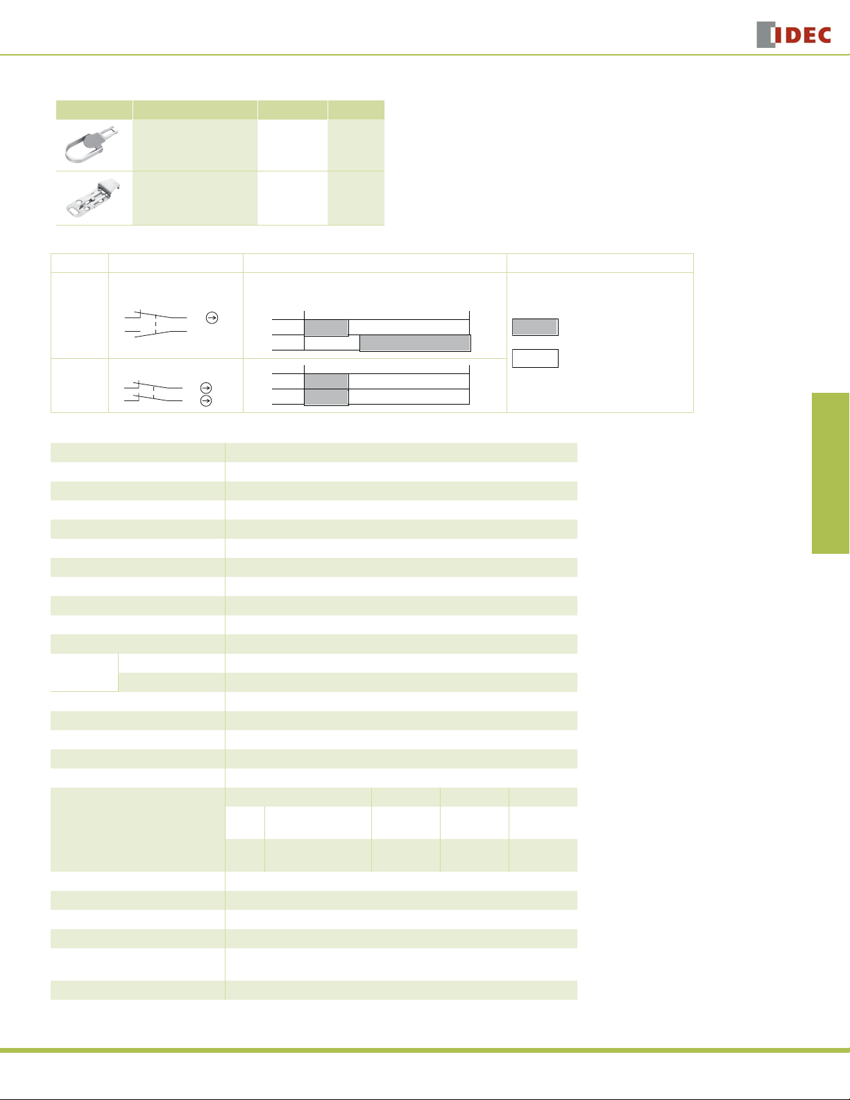
Accessories
Appearance Description Part Number Weight
HS5B/HS5E Plug Actuator
(allows switch to be used as
interlock plug unit)
HS5B/HS5E Padlock Hasp
(prevents unauthorized
insertion of actuator)
Contact Confi guration & Operation Chart
Model Contact Confi guration Contact Operation Chart Contact Status
1NC-1NO
HS5B-11
HS5B-02
3
2NC
3
Zb
Zb
4
21
4
21
Specifi cations
Conforming to Standards EN1088, IEC60947-5-1, EN60947-5-1, GS-ET-15, UL508
Operating Temperature –20 to +70˚C (no freezing)
Storage Temperature –40 to +80˚C
Operating Humidity 85% RH maximum (no condensation)
Altitude 2,000m maximum
Rated Insulation Voltage (Ui) 300V
Impulse Withstand Voltage (Uimp) 4 kV
Insulation Resistance 100MΩ minimum (500V DC megger)
Electric Shock Protection Class Class II (IEC61140)
Pollution Degree 3 (IEC60664-1)
Degree of Protection IP67 (IEC60529)
Vibration
Resistance
Shock Resistance 1,000 m/sec2 (approx. 100G)
Actuator Operating Speed 1 m/sec maximum
Positive Opening Travel 8 mm minimum
Positive Opening Force 60N minimum
Thermal Current (Ith) 10A
Rated Operating Current (Ie)
Operating Frequency 900 operations/hour
Mechanical Life 1,000,000 operations
Electrical Life 100,000 operations (rated load)
Conditional Short-circuit Current 100A (IEC60947-5-1)
Recommended Short
Circuit Protection
Weight Approx. 80g
Operating Extremes 10 to 55 Hz, amplitude 0.5 mm
Damage Limits 60 m/sec2 (approx. 6G)
HS9Z-A5P 35g
HS9Z-PH5 35g
Actuator
inserted
completely
3–4
1–2
3–4
1–2
Operating Voltage (Ue) 30V 125V 250V
Resistive load (AC12)
AC
Inductive load (AC15)
Resistive load (DC12)
DC
Inductive load (DC13)
250V, 10A fuse (Type D01 based on IEC60269-1, 60269-2)
10A
10A
8A
4A
Actuator
removed
completely
10A
5A
2.2A
1.1A
6A
3A
1.1A
0.6A
HS5B Series
Overview X Series E-Stops Door Interlock Switches Enabling Switches Barriers AS-Interface Safety at Work
ON (closed)
OFF (open)
USA: 800-262-IDEC Canada: 888-317-IDEC
351
Page 3
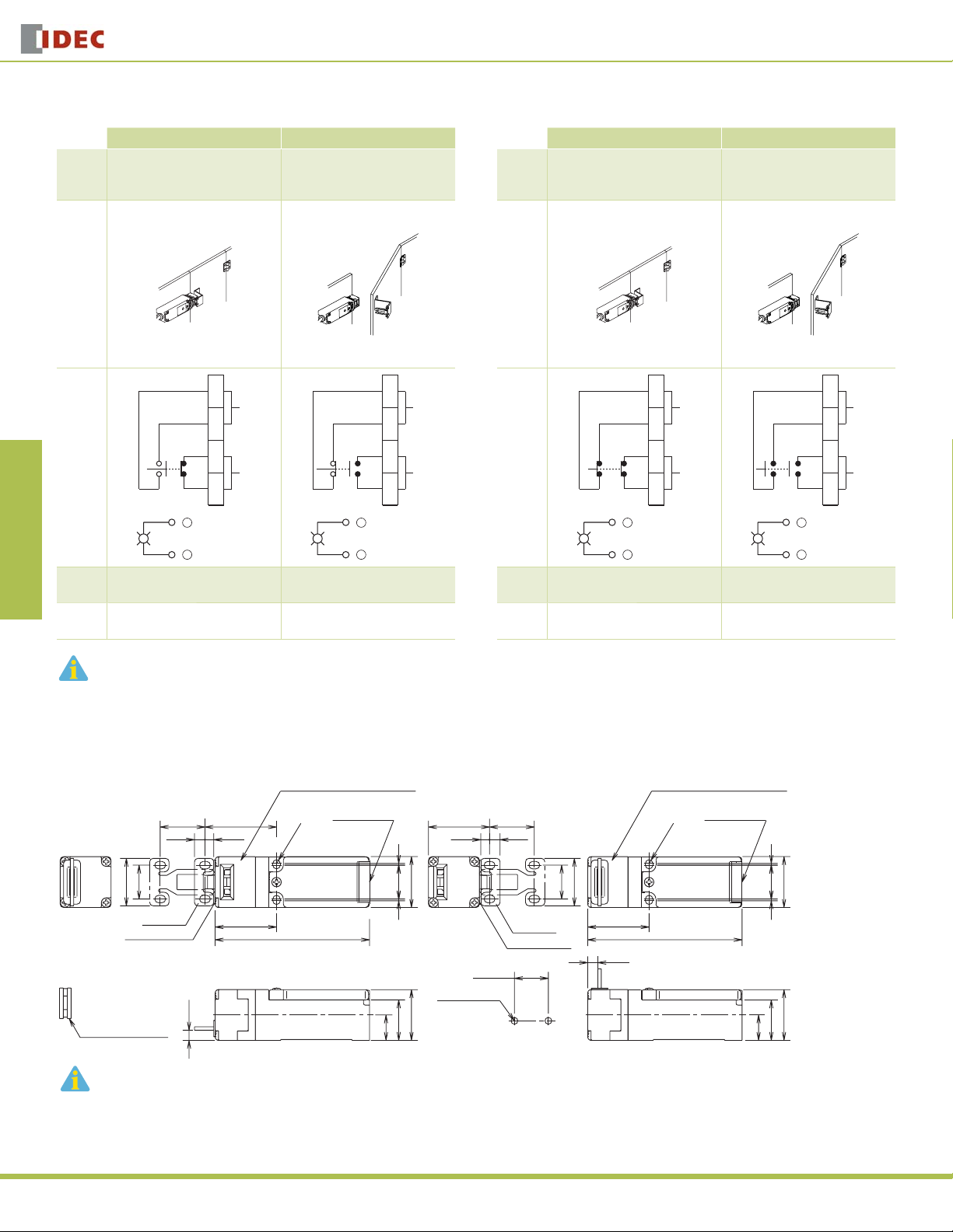
HS5B-11 (1NO-1NC)
OverviewX Series E-StopsDoor Interlock SwitchesEnabling SwitchesBarriersAS-Interface Safety at Work
Door/
Switch
Status
•
•
HS5B Series
Status 1 Status 2
Door Closed
Machine ready to operate
Application Examples and Circuit Diagrams
HS5B-02 (2NC)
Status 1 Status 2
Door opened
•
•
Machine cannot be started
Door/
Switch
Status
Door Closed
•
•
Machine ready to operate
Door Interlock Switches
Door opened
•
•
Machine cannot be started
Door
1
2
Auxiliary Circuit
Circuit
3
Diagram
4
Main Circuit
+
-
Main
Circuit
Aux.
Circuit
1. Main Circuit: used to enable the machine to start only when the main circuit is closed.
2. Auxiliary Circuit: used to indicate whether the machine circuit or door is open or closed.
3-4: Closed 3-4: Open
1-2: Open 1-2: Closed
+
-
1
2
3
4
Auxiliary Circuit
Main Circuit
Door
Circuit
Diagram
Main
Circuit
Aux.
Circuit
1
2
Auxiliary Circuit
3
4
Main Circuit
+
-
+
-
3-4: Closed 3-4: Open
1-2: Closed 1-2: Open
1
2
3
4
Auxiliary Circuit
Main Circuit
Plastic Head - using the straight actuator (HS9Z-A51)
Plastic Head (black or gray) Plastic Head (black or gray)
RP RP
26.4
6.2
20
28
Actuator
Actuator Stop
RP: Actuator Mounting Reference Position
Slot Plug (supplied)
(Note)
Plug the unused actuator insertion slot using the slot plug supplied with the interlock switch.
42.2
5.2
36.2
6±1
R2.2
91
Conduit Port Conduit Port
Dimensions (mm)
36 26.4
5.2 6.2
30
1 20 1
20 to 22
2-M4 Screws
30
24
15
Mounting Hole Layout
20
Actuator
Actuator Stop
R2.2
28
36.2
91
6±1
30
1 20 1
30
24
15
352
www.idec.com
Page 4
Door Interlock Switches
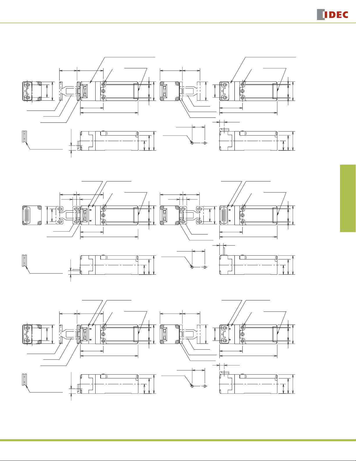
Dimensions (mm), continued
Plastic Head – using the Right-angle actuator (HS9Z-A52)
Plastic Head (black or gray) Plastic Head (black or gray)
HS5B Series
Overview X Series E-Stops Door Interlock Switches Enabling Switches Barriers AS-Interface Safety at Work
RP RP
27.7
30
20
Actuator Cover
Actuator
Actuator Stop
Slot Plug (supplied)
(Note)
Note: Plug the unused actuator entry slot using the slot plug supplied with the interlock switch.
41.5 35.3
R2.2
36.2
91
7.6±1
Conduit Port
1
201
30
20 to 22
2-M4 Screws
30
24
15
Mounting Hole Layout
Metal Head - using the straight actuator (HS9Z-A51A)
Metal Head Metal Head
RP RP
26.4
6.2
20
28
Actuator
Actuator Stop
RP: Actuator Mounting Reference Position
Slot Plug (supplied)
(Note)
42.2
5.2
36.2
6±1
R2.2
91
Conduit Port Conduit Port
1 20 1
24
15
36 26.4
5.2 6.2
30
20 to 22
2-M4 Screws
30
Mounting Hole Layout
27.7
30
Actuator
Actuator Cover
Actuator Stop
Actuator
Actuator Stop
Conduit Port
R2.2
20
36.2
20
28
36.2
6±1
91
7.6±1
Plastic (gray)Plastic (gray)
R2.2
91
30
1 20 1
30
24
15
30
1 20 1
30
24
15
Metal Head – using the Right-angle actuator (HS9Z-A52A)
Metal Head
RP RP
27.7
30
20
Actuator Cover
Actuator
Actuator Stop
Slot Plug (supplied)
(Note)
Note: Plug the unused actuator insertion slot using the slot plug supplied with the interlock switch.
41.5 35.3
36.2
7.6±1
Plastic (gray)
Conduit Port
R2.2
91
27.7
1
201
30
Actuator Cover
20 to 22
2-M4 Screws
30
24
15
Mounting Hole Layout
USA: 800-262-IDEC Canada: 888-317-IDEC
30
Actuator
Actuator Stop
Metal Head
20
36.2
7.6±1
Plastic (gray)
Conduit Port
R2.2
91
30
1 20 1
30
24
15
353
Page 5

HS5B Series
2
Straight Actuator - HS9Z-A51
(mainly for sliding doors)
6.2
5.2
OverviewX Series E-StopsDoor Interlock SwitchesEnabling SwitchesBarriersAS-Interface Safety at Work
28
4-R 2.2
Actuator Mounting Hole Layout
•
(Straight, Right-angle)
Straight Actuator with rubber bushings
- HS9Z-A51A (mainly for sliding doors)
32.4
(6)
0.8
20
6.4
Actuator Stop (Note)
10
2-M4 Screw
7.3
2-ø4.3
15.3
15
26
2
20
43.8
0.8
Actuator Key Dimensions (mm)
Right-angle Actuator - HS9Z-A52
(mainly for hinged doors)
33
2 7.27.2
30
28
0.84.5
Actuator Stop (Note)
2
15
2-ø4.4
20
1.6
Right-angle Actuator with rubber bushings
- HS9Z-A52A (mainly for hinged doors)
(11.2)
(39.7)
0.8
Door Interlock Switches
Adjustable Actuator - HS9Z-A55
Horizontal Swing
Orienting
Insert
49
15
Vertical Swing
Orienting
Insert
• Actuator Mounting Hole Layout
(horizontal/vertical swing)
2-M4 Screw
Angle Adjustment
(M3 Hexagon Socket Head Screw)
3
Actuator Stop
(Note)
7
29
18.5
Actuator Stop
(Note)
0.8
Angle Adjustment
(M3 Hexagon Socket Head Screw)
38
26
38
1
23
R2.1
(M4 Holes)
3.6
°
20
2
°
20
30
12
(20)
Actuator Stop (Note)
Washer (supplied with the actuator)
2-ø10
0.8
2-ø9
Rubber Cushion
(5)
The mounting center distance is set to 12 mm at factory. When 20-mm distance is required, adjust the
•
15
2
30
Rubber
Cushion
(5)
15.8
8.5
2-ø9
Washer (supplied
with the actuator)
0.8
2-ø10
Actuator Stop (Note)
(20)
15
12
2-ø4.3
2
distance by moving the rubber bushings.
The actuator has fl exibility to the directions indicated by the arrows. When 20-mm distance is selected, the
•
actuator swings vertically.
Actuator Mounting Hole Layout
(straight with rubber bushing, right-angle with rubber bushing)
2-M4 Screw
12
Mounting centers can be widened to
20 mm by moving the rubber
cushions.
Accessory Dimensions (mm)
HS9Z-A5P
Rivet: Stainless Steel
Handle: Aluminum
Thickness: 2
(30)
36
Washer: Steel
10
61.5
R46
15.5
HS5B Interlock
Switch
Spacer: Steel
4346
22
40
Actuator:
Area
30.5
10.5
Stainless Steel
Thickness: 2.5
Area
Coating: Orange
6.5
(36.2)
(91)
(30)
HS9Z-PH5
(30)
28
Rivet:
Stainless Steel
HS5B Interlock Switch
Actuator Orientation (Angle Adjustable)
The angle of actuator swing can be changed using the orienting insert (white plastic) installed on the back of the actuator.
Do not lose the orienting insert, otherwise the actuator will
not operate properly.
The actuator stop is supplied with the actuator and used
when adjusting the actuator position. Remove the actuator stop after the actuator position is determined.
2-R4
8
2-ø8
16.5
7.57.5
ø4
15.5
32
38.5
48
65
24
27.5
(30)
Material: SPCC
Thickness: 1.6
9
(36.2)
(91)
Material: SPCC
Thickness: 2.0
354
www.idec.com
Page 6

Door Interlock Switches
HS5B Series
Mounting Examples
Mount the interlock switch as shown in the examples below.
Mounting on Sliding Doors
Door
HS9Z-A51
Actuator
HS5B
Interlock Switch
Door Stop
Mounting on Hinged Doors
Hinged
Door
Latch
HS9Z-A51
Actuator
HS9Z-A52
Actuator
HS5B
Interlock Switch
Mounting the HS5B Head
The metal head for the HS5E interlock switch cannot be used on the HS5B. Be
sure to use the plastic head or metal head for the HS5B. Take care particularly
when using both HS5B and HS5E together.
HS5B HS5E
Plastic
(black or gray)
Metal
(gray)
Metal HeadMetal HeadPlastic Head
(black)
Applicable Crimping Terminal
When using crimping terminals, be sure to install insulation tubes on the crimping terminals to prevent electric shocks.
3.6 min.
ø3.6 min.
3.5 max.
6.9 max.
Wire Crimping Terminal
Approx. 4
Insulation Tube
Applicable Wire Size
0.5 to 1.25 mm2 (AWG20 to AWG16)
•
Recommended Tightening Torque of Mounting Screws
Interlock Switch: 2.0 ± 0.2 N·m (two M4 screws) *
•
Actuator Keys
•
-HS9Z-A51: 2.0 ± 0.2 N·m (two M4 screws) *
-HS9Z-A52: 1.0 ± 0.2 N·m (two M4 Phillips screws)
-HS9Z-A51A/A52A: 1.0 to 1.5 N·m (two M4 screws) *
-HS9Z-A55: 1.0 to 1.5 N·m (two M4 screws) *
*The above recommended tightening torques of the mounting screws are the
values confi rmed with hex socket head bolts. When other screws are used and
tightened to a smaller torque, make sure that the screws do not come loose
after mounting.
•
Mounting bolts must be provided by user.
•
To avoid unauthorized or unintended removal of the interlock switch and the
actuator, it is recommended that the interlock switch and the actuator be
installed in an unremovable manner, for example using special screws or
welding the screws.
•
When installing HS9Z-A51A or HS9Z-A52A actuator keys, use the washer
(supplied with the actuator) on the hinged door, and mount tightly using two
M4 screws.
Overview X Series E-Stops Door Interlock Switches Enabling Switches Barriers AS-Interface Safety at Work
Rotating the Head
The head of the HS5B can be rotated by removing the four screws from the
corners of the HS5B head and reinstalling the head in the desired orientation.
When reinstalling the head, make sure that no foreign object enters the interlock
switch. Tighten the screws. If the screws are loose it may cause the switch to
malfunction.
Recommended screw tightening torque: 1.0 ±0.1 N·m
Alternative Head OrientationsFactory Setting
Mounting Centers
12 mm (factory setting), adjustable to 20 mm
M4 Screw
Washer
Rubber Bushing
Hinged Door
M4 Tapped Hole
Note: Choose mounting centers either 12 mm or 20 mm.
Conduit Port Size Identifi cation
Conduit port size is identifi ed by the arrow on the back of the HS5B interlock
switch. The following example shows the identifi cation of the M20 conduit port
size.
M20
PG
22
20
M4 x 2
Arrow
Marking Conduit Port Size
G G1/2
PG PG13.5
M20 M20
G
USA: 800-262-IDEC Canada: 888-317-IDEC
355
Page 7

HS5B Series
Actuator Angle Adjustment
Using the screw (M3 hex socket head screw), the actuator angle can be
•
adjusted (refer to the dimensional drawing). Adjustable angle: (0˚) to 20˚
The larger the adjusted angle of the actuator, the smaller the applicable
•
radius of the door opening.
OverviewX Series E-StopsDoor Interlock SwitchesEnabling SwitchesBarriersAS-Interface Safety at Work
Door Interlock Switches
After installing the actuator, open the door. Then adjust the actuator so that
•
its edge can be inserted properly into the entry slot of the safety switch.
Recommended tightening torque: 0.8 N-m (approx. 8.0 kgf-cm)
•
After adjusting the actuator angle, apply loctite or the like to the adjustment
•
screw to prevent it from loosening.
Minimum Radius of Hinged Door
When using the interlock switch on hinged doors, refer to the minimum radius
•
of doors shown below. When using on doors with small minimum radius, use
the angle adjustable actuator (HS9Z-A55).
Note: Because deviation or dislocation of hinged doors may occur in actual applications, make sure
of the correct operation before installation.
When using the HS9Z-A52 Actuator
•
When the door hinge is on the extension line of the interlock switch surface:
Minimum Radius
Minimum Radius
170 mm
Door Hinge
•
When door hinge is on the extension line of the actuator mounting surface:
Minimum Radius
230 mm
Door Hinge
190 mm
Minimum Radius
260 mm
Door Hinge
Door Hinge
When using the HS9Z-A55 Angle Adjustable Actuator
When door hinge is on the extension line of the interlock switch surface:
•
50 mm
When door hinge is on the extension line of the actuator mounting surface:
•
70 mm
Horizontal Swing
Minimum Radius
50 mm
Vertical Swing
Minimum Radius
50 mm
Door Hinge
Door Hinge
Minimum Radius
70 mm
Minimum Radius
70 mm
Door Hinge
Door Hinge
Actuator Angle Adjustment for the HS9Z-A55
Using the angle adjustment screw, the actuator angle can be adjusted (see
•
fi gures on page 354). Adjustable angle: 0 to 20°
The larger the adjusted angle of the actuator, the smaller the applicable
•
radius of the door opening.
After installing the actuator, open the door. Then adjust the actuator so that
•
its edge can be inserted properly into the actuator entry slot of the interlock
switch.
After adjusting the actuator angle, apply Loctite to the adjustment screw so
•
that the screw will not loosen.
Use a cable gland with a degree of protection IP67
G1/2, PG13.5, M20
9 max.
30 max.
When Using Flexible Conduits (Example)
Flexible conduit example: VF-03 (Nihon Flex)
Conduit Port Size Plastic Cable Gland Metal Cable Gland
G1/2 — RLC-103 (Nihon Flex)
PG13.5 — RBC-103PG13.5 (Nihon Flex)
M20 — RLC-103EC20 (Nihon Flex)
356
Applicable Cable Glands
When Using Multi-core Cables (Example)
Conduit Port Size Plastic Cable Gland Metal Cable Gland
G1/2 SCS-10*
all dimensions in mm
PG13.5 ST13.5
M20 ST-M20X1.5
•
Different cable glands are used depending on the cable sheath outside diameter. When
purchasing a cable gland, confi rm that the cable gland is applicable to the cable sheath
outside diameter.
•
When using a 1/2-14NPT cable gland, use the HS5B interlock switch with M20 conduit
port (Part No.: HS5B-***BM) together with an adapter (Part No.: MA-M/NPT 20X1.5
5402-0110, K-MECS) and a gasket (Part No.: GP M20, K-MECS). Install a gasket between
the interlock switch and the adapter. Apply sealing tape between the cable gland and
the adapter to make sure of IP67 protection for the enclosure.
www.idec.com
(Seiwa Electric)
(K-MECS)
(K-MECS)
ALS-16**
(Nihon Flex)
ABS-**PG13.5
(Nihon Flex)
ALS-**EC20
(Nihon Flex)
Page 8

Door Interlock Switches
Safety Precautions
In order to avoid electric shock or a fi re, turn the power off before installation,
•
removal, wire connection, maintenance, or inspection of the switch.
If relays are used in the circuit between the safety switch and the load,
•
consider degrees of the danger and use safety relays, since welded or sticking
contacts of standard relays may invalidate the functions of the safety switch.
Operation Precautions - for all series
Regardless of door types, do not use the safety switch as a door stop. Install
•
a mechanical door stop at the end of the door to protect the safety switch
against excessive force.
Do not apply excessive shock to the switch when opening or closing the door.
•
A shock to the door exceeding 1,000 m/sec2 (approx. 100G) may cause the
•
contacts of the switch to chatter, and a malfunction of the switch may occur.
For connection of wires, unscrew the cover. Unnecessary loosening of other
•
screws may cause a malfunction of the switch.
HS5E/HS5B Precautions
For Rotating Head Directions
•
The heads of the HS5E/HS5B can be rotated in 90° increments after removing
the 4 screws on the corners of the head. Prevent entry of foreign objects into
the switch during removal of the head. Tighten these screws with torque
designated in the instruction sheet. Improper torque may cause errors.
Precautions
Do not place a PLC in the circuit between the safety switch and the load. The
•
safety security can be endangered in the event of a malfunction of the PLC.
Do not disassemble or modify the switch. It may cause a breakdown or an
•
accident.
Prevent foreign objects such as dust and liquids from entering the switch
•
while connecting conduit or wiring.
If the operating atmosphere is contaminated, use a protective cover to
•
prevent the entry of foreign objects into the switch through the actuator entry
slots.
Entry of a considerable amount of foreign objects into the switch may affect
•
the mechanism of the switch and cause a breakdown.
Do not store the switches in a dusty, humid, or organic-gas atmosphere.
•
Note: Because deviation or dislocation of hinged doors may occur in actual
applications, make sure of the correct operation before installation.
When using the HS9Z-A52 Actuator
•
When the door hinge is on the extension line of the interlock switch surface:
Overview X Series E-Stops Door Interlock Switches Enabling Switches Barriers AS-Interface Safety at Work
Head can be rotated.Factory Setting
Minimum Radius of Hinged Doors
When using the interlock switch on hinged doors, refer to the minimum radius
•
of doors shown below. When using on doors with small minimum radius, use
the angle adjustable actuator (HS9Z-A55).
HS2B Precautions
Wire Connection
The HS2B has 3 conduit ports, which are closed as a part of the molded
•
switch housing.
Make an opening for wire connection by breaking one of the conduit-port
•
knockouts on the switch housing using a screwdriver.
Minimum Radius
Minimum Radius
170 mm
Door Hinge
•
When door hinge is on the extension line of the actuator mounting surface:
Minimum Radius
230 mm
Door Hinge
•
Cracks or burrs on the conduit entry may deteriorate the housing protection
190 mm
Door Hinge
Minimum Radius
260 mm
Door Hinge
against water.
•
When changing to another conduit port, close the unused opening with an
optional plug (Part No. HS9Z-P1).
When breaking the conduit port, take care not to damage the contact block or
•
other parts inside the switch.
USA: 800-262-IDEC Canada: 888-317-IDEC
397
Page 9

Precautions
Door Interlock Switches
HS1E Precautions
Wire Connection
•
Make an opening for wire connection by breaking one of the conduit-port
knockouts on the switch housing using a screwdriver.
OverviewX Series E-StopsDoor Interlock SwitchesEnabling SwitchesBarriersAS-Interface Safety at Work
•
Before breaking the knockout, temporarily remove the connector-fi xing lock
nut from the switch.
•
When breaking the knockout, take care not to damage the contact block or
other parts inside the switch.
•
Cracks or burrs on the conduit entry may deteriorate the housing protection.
•
When changing to the other conduit port, close the unused opening with an
optional plug (accessory).
Plug
Type No. HS9Z-P1
Manual Unlocking
Remove the screw located on the unlocking entry at the side of the switch us-
•
ing the key wrench included with the switch. Then insert a small screwdriver
into the switch to push the lever inside of the switch toward the indicator
until the actuator is unlocked (refer to the diagram on the right).
1. This unlocking method is intended for an escape from a machine when a person is
locked in. For access to the unlocking entry, an access hole should be opened on the
mounting panel. When opening the hole, apply proper protection against water or other
foreign objects.
2. Caution: After the unlocking operation, put the screw back into the unlocking entry
for safety.
Unlock
Manual Unlocking Position
Screwdriver
M5
Unlock
Normal Position
89
26
23.5
Insert a small screwdriver into the elliptical hole on the back of the switch,
•
then push the lever inside of the switch toward the indicator until the actuator
is unlocked (refer to the diagram on the right).
HS1C Precautions
Regardless of door type, do not use the safety switch as a locking device.
•
Install a locking device independently, for example, using a metal latch (also
applicable to HS1E).
The safety switch cover can be only removed with the special key wrench
•
supplied with the switch or with the optional screwdriver (also applicable to
HS1B and HS1E).
Remove the screw located on the unlocking entry at the side of the switch us-
•
ing the key wrench included with the switch. Then insert a small screwdriver
into the switch to push the lever inside of the switch toward the indicator
until the actuator is unlocked (refer to the diagram on the right).
Caution: After the unlocking operation, put the screw back into the unlocking
entry for safety.
Screwdriver
398
www.idec.com
Page 10

Door Interlock Switches
Precautions
Operation Precautions
Applicable Crimping Terminals
(Refer to the Crimping Terminal 1 or 2 shown in the drawing below.)
•
HS1C
•
Terminals No. 1 to 6: Use solid or stranded wires only (crimping terminals
not applicable).
Terminals No. 7 and 8: Crimping Terminal 1
Ground Terminal: Crimping Terminal 2
HS1B
•
Ground Terminal: Crimping Terminal 2
Other Terminals: Crimping Terminal 1
HS2B, HS5B, and HS1E
Crimping Terminal 1
3.6 min.
ø3.6 min.
Crimping Terminal 1
Use an insulation tube on the crimping terminal.
3.5 max.
6.9 max.
Approx. 4mm
Wire
Insulation Tube
3.5 min.
ø4.1 min.
Crimping Terminal 2
Crimping Terminal
3.8 max.
7.6 max.
Applicable Connectors (As shown below)
•
Use connectors which maintain the IP67 protection.
•
Applicable Connector Dimensions
•
Flex Conduit: VF03 (Japan Flex) www.nipolex.co.jp
•
Steel Connector (G1/2): ALC-103
(PF13.5): RBC-103PG13.5
G1/2
9 mm max.
Recommended Screw Tightening Torque
HS1C: 5.0±0.5 N-m (approx. 50±5 kgf-cm)
•
(4 or 6 pcs of M5 hex socket head cap screws)
HS1B: 5.0±0.5 N-m (approx. 50±5 kgf-cm)
•
(2 or 4 pcs. of M5 hex socket head cap screws)
HS2B: 5.0±0.5 N-m (approx. 50±5 kgf-cm)
•
(2 pcs of M5 hex socket head cap screws)
HS5B: 4.0±0.4 N-m (approx. 40±4 kgf-cm)
•
(2 pcs of M4 hex socket head cap screws)
HS1E: 5.0±0.5 N-m (approx. 50±5 kgf-cm)
•
(4 or 6 pcs of M5 hex socket head cap screws)
30 mm
max.
Overview X Series E-Stops Door Interlock Switches Enabling Switches Barriers AS-Interface Safety at Work
Installation Examples (see the diagrams below)
Mounting on Sliding Doors
Door
HS9Z-A1 Actuator
Door Stop
Mounting on Hinged Doors
Latch
HS9Z-A1 Actuator
HS9Z-A2 Actuator
Actuator (HS9Z-A1/A2)
•
5.0±0.5 N-m (approx. 50±5 kgf·cm)
(2 pcs. of M6 hex socket head cap screws)
•
Actuator (HS9Z-A51/A52)
2.0±0.2 N-m (approx. 20±2 kgf·cm)
•
(2 pcs of M4 hex socket head cap screws)
1.0±0.2 N-m (approx. 10±2 kgf·cm)
•
(2 pcs of M4 Phillips screws)
The screws are supplied by the user.
Applicable Wire Size
HS1C: 0.5 to 0.75 mm2 (Terminals No.1, 2, 5 to 8)
•
1.0 to 1.25 mm2 (Terminals No.3, 4, and grounding terminal)
HS5B: 0.5 to 1.25 mm2
•
HS1E: 0.5 to 1.25 mm2
•
USA: 800-262-IDEC Canada: 888-317-IDEC
399
Page 11

Precautions
Actuator Angle Adjustment
Using the screw (M3 hex socket head screw), the actuator angle can be
•
adjusted (refer to the dimensional drawing). Adjustable angle: (0˚) to 20˚
The larger the adjusted angle of the actuator, the smaller the applicable
•
radius of the door opening.
OverviewX Series E-StopsDoor Interlock SwitchesEnabling SwitchesBarriersAS-Interface Safety at Work
Minimum Radius of Hinged Door
When using the interlock switch on hinged doors, refer to the minimum radius
•
of doors shown below. When using on doors with small minimum radius, use
the angle adjustable actuator (HS9Z-A55).
Note: Because deviation or dislocation of hinged doors may occur in actual applications, make sure
of the correct operation before installation.
When using the HS9Z-A52 Actuator
•
When the door hinge is on the extension line of the interlock switch surface:
Minimum Radius
Minimum Radius
170 mm
190 mm
Door Interlock Switches
After installing the actuator, open the door. Then adjust the actuator so that
•
its edge can be inserted properly into the entry slot of the safety switch.
Recommended tightening torque: 0.8 N-m (approx. 8.0 kgf-cm)
•
After adjusting the actuator angle, apply loctite or the like to the adjustment
•
screw so as to prevent its loosening.
Horizontal Swing
Minimum Radius
50 mm
Door Hinge
Vertical Swing
Minimum Radius
70 mm
Door Hinge
Door Hinge
•
When door hinge is on the extension line of the actuator mounting surface:
Minimum Radius
230 mm
Door Hinge
Minimum Radius
Door Hinge
260 mm
Door Hinge
When using the HS9Z-A55 Angle Adjustable Actuator
When door hinge is on the extension line of the interlock switch surface:
•
50 mm
When door hinge is on the extension line of the actuator mounting surface:
•
70 mm
Applicable Cable Glands
Use a cable gland with a degree of protection IP67
G1/2, PG13.5, M20
9 max.
When Using Flexible Conduits (Example)
Flexible conduit example: VF-03 (Nihon Flex)
Conduit Port Size Plastic Cable Gland Metal Cable Gland
G1/2 — RLC-103 (Nihon Flex)
PG13.5 — RBC-103PG13.5 (Nihon Flex)
M20 — RLC-103EC20 (Nihon Flex)
30 max.
all dimensions in mm
Minimum Radius
50 mm
Door Hinge
Minimum Radius
70 mm
Door Hinge
Actuator Angle Adjustment for the HS9Z-A55
Using the angle adjustment screw, the actuator angle can be adjusted (see
•
fi gures on page 370. Adjustable angle: 0 to 20°
The larger the adjusted angle of the actuator, the smaller the applicable
•
radius of the door opening.
After installing the actuator, open the door. Then adjust the actuator so that
•
its edge can be inserted properly into the actuator entry slot of the interlock
switch.
After adjusting the actuator angle, apply Loctite to the adjustment screw so
•
that the screw will not loosen.
When Using Multi-core Cables (Example)
Conduit Port Size Plastic Cable Gland Metal Cable Gland
G1/2 SCS-10*
PG13.5 ST13.5
M20 ST-M20X1.5
Different cable glands are used depending on the cable sheath outside diameter. When
•
purchasing a cable gland, confi rm that the cable gland is applicable to the cable sheath
outside diameter.
When using a 1/2-14NPT cable gland, use the HS5B interlock switch with M20 conduit
•
port (Part No.: HS5B-***BM) together with an adapter (Part No.: MA-M/NPT 20X1.5
5402-0110, K-MECS) and a gasket (Part No.: GP M20, K-MECS). Install a gasket between
the interlock switch and the adapter. Apply sealing tape between the cable gland and
the adapter to make sure of IP67 protection for the enclosure.
(Seiwa Electric)
(K-MECS)
(K-MECS)
ALS-16**
(Nihon Flex)
ABS-**PG13.5
(Nihon Flex)
ALS-**EC20
(Nihon Flex)
400
www.idec.com
 Loading...