

IDEC HS1C Series Catalog
HS1C features:
Rugged Aluminum Die-cast Housing
•
With the actuator mounted on a movable door, and the switch on a machine, the door
•
OverviewX Series E-StopsDoor Interlock SwitchesEnabling SwitchesBarriersAS-Interface Safety at Work
can be mechanically locked when closed.
Greater Safety: The door is unlocked by a solenoid lock-release signal from a PLC or
•
another source after the machine has stopped.
In the event of power failure or for machine maintenance, the door can be unlocked
•
using a special tool.
Flexible Installation: The actuator can be accessed from two directions.
•
Select from four different circuit confi gurations.
•
IP67 Protection
•
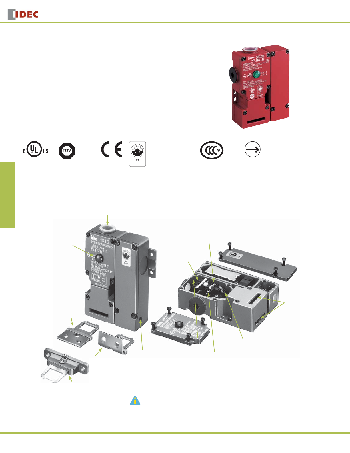
HS1C Series
HS1C Series Full Size Solenoid Locking Switches
Door Interlock Switches
HS1C Series Functionality
Two Conduit Ports (G1/2)
Use IP67 conduit or
gland
LED Indicator
(green or red)
Straight Actuator
(SUS304)
EN1088
EN60947-5-1
IEC60947-5-1
GS-ET-15
BG standard in Germany
Tubular Clamp
Terminal Block (M3)
Certifi cate No.
20005010305145652
Contact Mechanism
(Direct Opening Action)
Direct Opening Action
Two Actuator
Entry Slots
392
Right-angle Actuator
(SUS304)
Angle Adjustable Actuator
for hinged doors
Manual Unlocking Entry (M4 hole)
Accessible using a small screwdriver
after removing a TORX screw on the
unlocking entry
TORX is a registered trademark of Camcar Textron.
www.idec.com
Ground Terminal (M4)
Indicator Terminal Block (M3.5)
Door Interlock Switches
HS1C Series
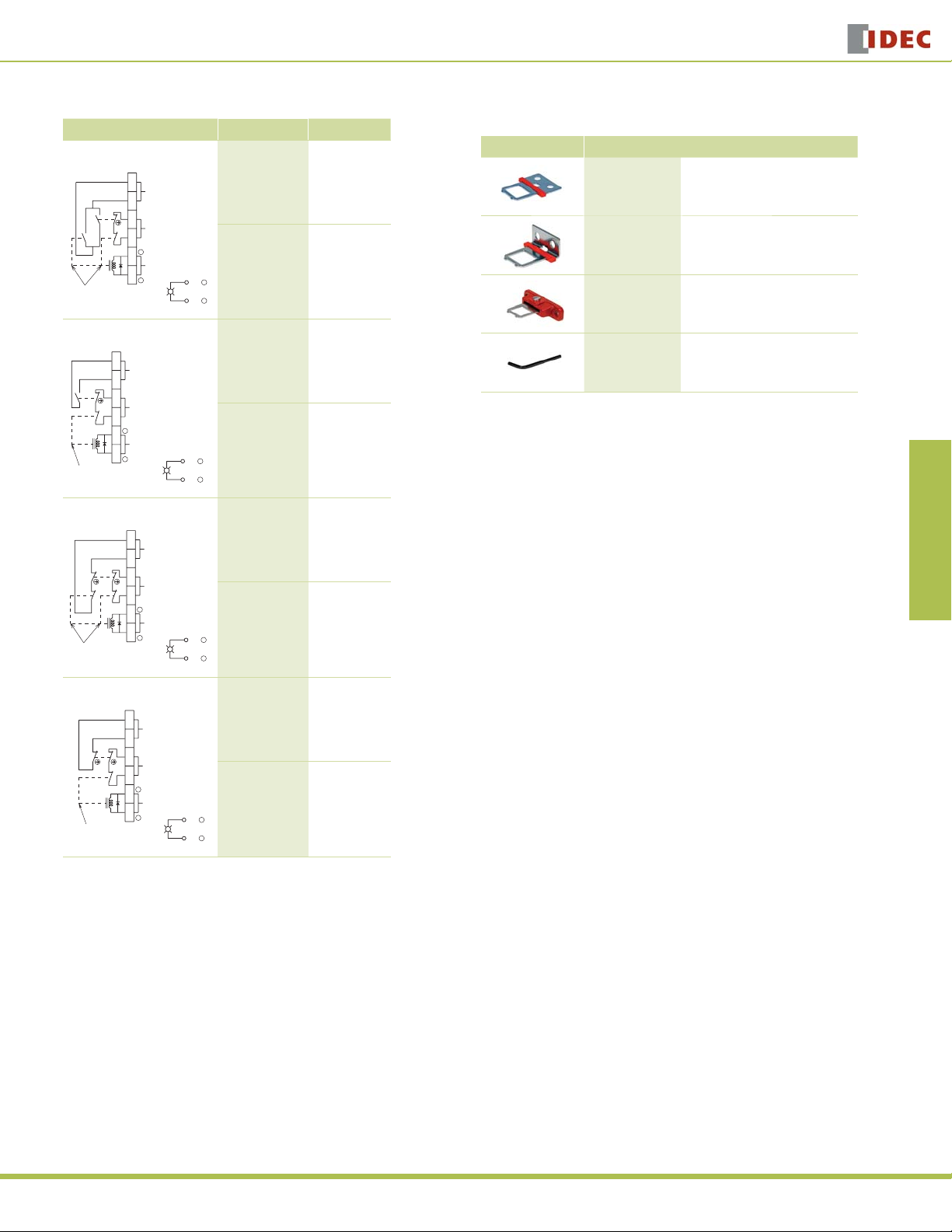
Part Numbers
Contact Confi guration Indicator LED Part Number
Main Circuit: 1NC+1NC
Auxiliary Circuit: 1NO/1NO
Contacts are linked
to the solenoid
mechanically
1
Auxiliary
Circuit
2
3
Main
Circuit
4
+
5
Indicator
6
Solenoid
Power
–
Green HS1C-R44R-G
Red HS1C-R44R-R
+
7
–
8
Main Circuit: 1NC+1NC
Auxiliary Circuit: 1NO
1
2
3
4
+
5
6
Contacts are linked
to the solenoid
mechanically
–
Auxiliary
Circuit
Main
Circuit
Solenoid
Power
Indicator
Green HS1C-R144R-G
Red HS1C-R144R-R
+
7
–
8
Main Circuit: 1NC+1NC
Auxiliary Circuit: 1NC+1NC
Contacts are linked
to the solenoid
mechanically
1
Auxiliary
Circuit
2
3
Main
Circuit
4
+
5
Indicator
6
Solenoid
Power
–
Green HS1C-R244R-G
Red HS1C-R244R-R
+
7
–
8
Main Circuit: 1NC+1NC
Auxiliary Circuit: 1NC
1
2
3
4
5
6
Contacts are linked
to the solenoid
mechanically
+
–
Auxiliary
Circuit
Main
Circuit
Solenoid
Power
Indicator
Green HS1C-R344R-G
Red HS1C-R344R-R
+
7
–
8
Actuator Keys & Accessories
Item Part Number Description
HS9Z-A1
HS9Z-A2
HS9Z-A3 Adjustable Actuator
HS9Z-T1 Key Wrench (included with switch)
Straight Actuator
(Mainly for sliding doors)
Right-angle Actuator
(Mainly for rotating doors)
Overview X Series E-Stops Door Interlock Switches Enabling Switches Barriers AS-Interface Safety at Work
USA: 800-262-IDEC Canada: 888-317-IDEC
393
HS1C Series
Specifi cations
Conforming to Standards EN1088, IEC60947-5-1, EN60947-5-1, GS-ET-19, UL508
Operating Temperature –20 to +40˚C (no freezing)
Storage Temperature –40 to +80˚C
Operating Humidity 85% RH maximum (no condensation)
OverviewX Series E-StopsDoor Interlock SwitchesEnabling SwitchesBarriersAS-Interface Safety at Work
Altitude 2,000m maximum
Rated Insulation Voltage (Ui) 300V (between LED or solenoid and ground: 60V)
Impulse Withstand Voltage (Uimp) 4 kV (between LED or solenoid and ground: 2.5 kV)
Between live and dead metal parts: 100 MΩ minimum
Insulation Resistance
Electric Shock Protection Class Class 1 (IEC61140)
Pollution Degree 3 (IEC60947-5-1)
Degree of Protection IP67 (IEC60529)
Vibration
Resistance
Shock Resistance 1,000 m/s2 (approx. 100G)
Actuator Tensile Strength when Locked 1,500N minimum
Operating Speed 1 m/sec maximum
Positive Opening Travel 11 mm minimum
Positive Opening Force 20N minimum
Thermal Current (Ith) Main circuit: 10A, Auxiliary circuit: 3A
Rated Operating Current (Ie)
Contact Opening Distance Main circuit: 1.7 mm max., Auxiliary circuit: 1.2 mm min.
Operating Frequency 900 operations/hour max.
Mechanical Life 1,000,000 operations
Electrical Life 100,000 operations (rated load)
Conditional Short-circuit Current 100A (IEC60947-5-1)
Recommended Short Circuit Protection 250V, 10A fuse (Type D01 based on IEC60269-1, 60269-2)
Solenoid
Unit
Indicator
Weight Approx. 660g
Operating Extremes 10 to 55 Hz, amplitude 0.5 mm
Damage Limits 60 m/sec2 (approx. 6G)
Operating Voltage 24V DC
Current 415 mA
Coil Resistance 58Ω (at 20ºC)
Energizing Voltage Rated voltage x 85% maximum (at 20ºC)
De-energizing Voltage Rated voltage x 10% minimum (at 20ºC)
Continuous Applicable Voltage Rated voltage x 110%
Continuous Applicable Duration Not specifi cally limited
Insulation Class Class B
Operating Voltage 24V DC
Current 10 mA
Light Source LED lamp
Lens Color Red or Green (12 mm dia. Lens)
Between live metal part and ground: 100 MΩ minimum
Between live metal parts: 100 MΩ minimum
Between terminals of the same pole: 100 MΩ minimum
Operating Voltage (Ue) 30V 125V 250V
Resistive load (AC12)
AC
Inductive load (AC15)
Main
Circuit
Circuit
Auxiliary
Resistive load (DC12)
DC
Inductive load (DC13)
Resistive load (AC12)
AC
Inductive load (AC15)
Resistive load (DC12)
DC
Inductive load (DC13)
10A
10A5A6A
10A
6A
3A–0.9A––
–
3A–3A
–
3A
––0.9A––
Door Interlock Switches
Part Number Key
HS1C - R 1 4 4 R - R
3A
3A
Indicator Color
R (Red)
G (Green)
Housing Color
R (Red)
Solenoid and LED Voltage
4 (24V DC)
Circuit Code
Main Circuit Auxiliary Circuit
Blank: 1NC + 1NC 1NO/1NO
1: 1NC + 1NC 1NO
2: 1NC + 1NC 1NC + 1NC
3: 1NC + 1NC 1NC
394
www.idec.com
 Loading...