

IDEC HR2S Sales Brochure

HR2S
Safety Relay Modules
Compact Design and Maintenance Improvements for
Compact Design and Maintenance Improvements for
Outstanding Usability!
Outstanding Usability!
HR2S-301P
Compliant with
Performance level (PL) e
Category 4
EN ISO 13849-1
HR2S-301N
TÜV SÜD
European and North American (NRTL)
HR2S-332NT075/T15/T30
With time-delay output
SIMPLE
COMPACT
SAFETY
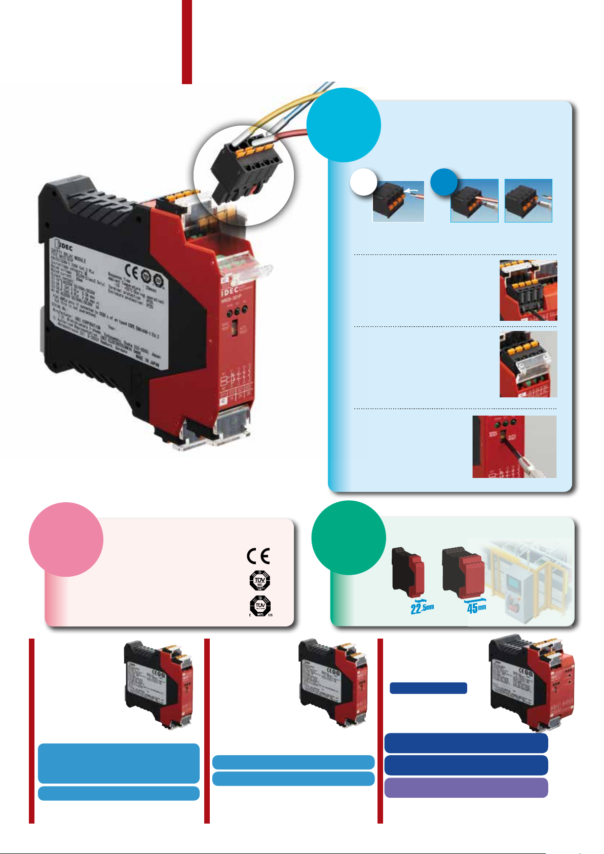
Slim safety relay module with spring
HR2S
Safety Relay Modules
terminals enables easy wiring!
SIMPLE
1
1
Removable terminal block
enables easy replacement
The terminals can be attached and
removed easily with a at screwdriver
allowing easy replacement of the
module.
The terminal cover detects
improper connection
The terminal cover does not close if
the terminal is not fully inserted into
the module.
Simple wiring procedure
No complex work required. Just insert a
ferrule into the terminal. The wire is locked
into the spring terminal so a screwdriver is not
required when inserting the wire.
Insert
No tools needed.
Directly insert a
ferrule into the terminal.
The wire is locked.
Removal
1
1
Insert a at
screwdriver
into the terminal
entrance.
2
2
Remove the
wire by releasing
the lock with a
screwdriver.
HR2S-301P
SAFETY
Complies with international standards
• Safety Category 4, Performance
Level e according to
EN ISO 13849-1: 2008
• TÜV SÜD
European and North American (NRTL)
HR2S-301P HR2S-301N
Operation modes can be
changed with a single
action
The switch on the front panel
allows switching between Auto
and Manual modes.
COMPACT
Compact design enables
installation in a narrow space
HR2S-301P
HR2S-301N
HR2S-332NT
HR2S-332NT075/15/30
Time-delay output
Not fully inserted
•Compliant with categories 2 and 3 when
used with a safety switch.
•Compliant with categories 2 (type 2) and
4 (type 4) when used with a safety light curtain.
3NO and 1NC output contacts
Auxiliary output (NC) can be used for monitoring.
2
Compliant with Category 4
3NO and 1NC output contacts
Auxiliary output (NC) can be used for monitoring.
3NO (safety output) and
3NO (time-delay safety output)
Time-delay output
compliant with category 4
Time setting can be selected from
31 different time ranges
· HR2S-332N-T075=0.5/1/1.5/2/2.5/3/3.5/4/4.5/5/5.5/6/6.5/7/7.5s
· HR2S-332N-T15=1/2/3/4/5/6/7/8/9/10/11/12/13/14/15s
· HR2S-332N-T30=2/4/6/8/10/12/14/16/18/20/22/24/26/28/30s

HR2S-301P/HR2S-301N Safety Relay Modules
Production
monitored
Safety
tested
Functional
Safety
HR2S-301P/HR2S301N
Contact Conguration
Safety Output Auxiliary Contact
3NO 1NC
Dimensions
13 23 3341
S34
A2A1
S33
SAFETY
RELAY MODULE
HR2S-301P
K1 K2
POW
MANU
RESET
AUTO
RESET
SEAL
All dimensions in mm
111.2
33
131441
23
K1
34
K2
24
42
S11
S12
S21S22
14 24 34
42
22.5
Terminal position (76.7)
Terminal position (95.7)
111
Package Quantity: 1
Input Supply Voltage Part No.
Positive 24V DC –15% to +10% HR2S-301P
Negative 24V DC –15% to +10% HR2S-301N
Specifications
EN ISO 13849-1: 2008
EN 954-1: 1996
Applicable Standards
Applicable Standards for Use EN 60204-1: 2006
Performance level (PL) e (EN ISO 13849-1)
Safety Category (Note 2) 3 or 4 (EN ISO 13849-1)
Stop Category 0 (IEC/EN 60204-1)
Operating Temperature –10 to +55°C (no freezing)
Relative Humidity 30 to 85% (no condensation)
Altitude 0 to 2000m (operating)
Insulation Resistance
Dielectric Strength
Shock Resistance
Bump
Vibration Resistance
Degree of Protection Terminals: IP20 Housing: IP40
Rated Voltage 24V DC –15% +10%
Power Consumption 2.2W (26.4V DC)
Overcurrent Protection Built-in, electronic (approx. 0.9A)
Contact Resistance
Turn-On Time 50 ms maximum (Note 4)
Minimum Applicable Load 24V DC / 5 mA (Reference value)
Response Time 20 ms maximum (Note 4) (Note 5)
Overvoltage Category III (IEC60664-1)
Pollution Degree 2 (IEC60664-1)
EN 50178: 1997
EN 55011/A2: 2007
EN 61000-6-2: 2005
UL508/R2005-07 (Note 1)
CAN/CSA C22.2 No.14: 2005 (Note 1)
100Ω minimum
(500V DC megger, same measurement
positions as dielectric strength)
Between outside housing and internal
circuit:
3,750V AC,1 minute
Between outputs of different poles:
2,500V AC, 1 minute
Between input and output terminals:
2,500V AC, 1 minute
Between power supply and output terminals:
2
, pulse width 11m sec, 3 shocks
300 m/s
in each of 3 axes
2
, pulse width 16m sec, 1000
100 m/s
times in each of 3 axes
2,500V AC ,1 minute
10 to 55 Hz, 1 octave/minute,
0.7 mmp-p in each of 3 axes, 20 sweeps,
5 to 55 Hz, 30 m/s
of 3 axes
2
, for 2 hours in each
200 mΩ maximum (Note 3)
Rated Insulation Voltage
(output contact)
Terminals
13-14
23-24
33-34
Rated Load
(Note 6) (Note 7)
Safety
Circuit
250V (IEC60664-1)
250V AC / 30V DC (resistive load) (Note 8)
Category 3 or lower: 5.0A maximum
Category 4 or lower: 3.6A maximum
AC15 240V AC / 2A cosø=0.3
DC13 24V DC / 1A L/R=48 ms
No. of Outputs 3 (NO contact output)
Rated Load
(Note 7)
Terminals
41-42
Output Contact Ratings
Safety
Circuit
250V AC / 30V DC (resistive load)
Category 3 or lower: 5.0A maximum
Category 4 or lower: 3.6A maximum
AC15 240V AC / 2A cosø=0.3
DC13 24V DC / 1A L/R=48 ms
No. of Outputs 1 (NC contact output)
Mechanical Durability 5,000,000 operations minimum
Electrical Durability 100,000 operations minimum
2
Wire Size 0.2 mm
to 1.5 mm2 (24 to 16 AWG)
Weight (approx.) 200g
Note 1: UL and CSA are approved by TÜV SÜD America Inc., an accredited
NRTL.
Note 2: HR2S-301N is recommended for use in category 4 safety
applications. The requirements of the safety category must be
determined according to the safety equipment. We recommend that
you consult a third party organization.
Categories may change depending on the combination of the safety
equipment. Categories may also change depending on the output
contact ratings.
Note 3: Measured using 5 or 6V DC, 1A voltage drop method.
Note 4: When measured at the rated voltage (at 20°C), excluding contact
bounce time.
Note 5: The time from when the safety input turns OFF to when the safety
output turns OFF.
Note 6: Leave 5 mm of space between the sides of the module when more
than 3A is continuously applied to the relay contact.
Note 7: The module is not suitable for use with a load less than the
minimum applicable load. Once a large load is applied, contacts
may not operate with a small load.
Note 8: The maximum current of the safety output contact is specied by
the approved standard.
Category 4 HR2S-301N, HR2S-301P + Type 4 OSSD’s 3.6A
Category 3 HR2S-301P 5.0A
•To prevent the safety output contact from overcurrent, use a fuse. To satisfy
Category 4, use a fuse with a maximum current of 3.6A. This fuse is not
required if the short circuit current is less than 5A.
3

HR2S-301P/HR2S-301N Safety Relay Modules
41 13 23 33
S34S33
Y2Y1
HR2S-301P
SAFETY
RELAY MODULE
K2
K1
POW
MANU
RESET
AUTO
RESET
42 14 24 34
S22S21S12S11
K2
K1
41 13 23 33
42 14 24 34
1
2
3
4
7
8
6
5
13 23 3341
S34
S33
A2A1
AUTO
RESET
MANU
RESET
POW
K1 K2
SAFETY
RELAY MODULE
HR2S-301P
42 14 24 34
S22S21S12S11
K2
K1
41 13 23 33
42 14 24 34
0V
24V DC
C
(1) Use a 3.6A maximum fuse for output
Terminal Arrangement
3
1
13 23 3341
S34
S33
8
7
6
5
HR2S-301P
POW
MANU
RESET
SAFETY
RELAY MODULE
K1 K2
AUTO
RESET
Part Description
Part No. Part Names and Functions
CN1: Power supply input,
1
start/off-check input
2 CN2: Safety input (dual channel)
A2A1
3 CN3: Safety output contact
4 CN4: Safety output contact
Switch: Select AUTO or MANU
5
mode
6 POW: Power LED
7 K1: ON-LED for safety output
8 K2: ON-LED for safety output
33
131441
23
K1
K2
34
24
42
S22
S21
S11
S12
14 24 34
42
2
4
HR2S-301P Wiring Diagram
Safety Category 4 Circuit Example (using a safety light curtain)
Terminal Arrangement
Terminal Markings I/O Signals Notes
A1
CN1
A2
S33
S34
S11
S12 Function
CN2
S21
S22 Function
41–42
CN3
CN4
13–14
23–24
33–34
Note: 5.0A max. Category 3 or lower HR2S-301P
3.6A max . Categ ory 4 HR2S-301N, HR2S-301P + Type 4 OSSD’s
Power supply
+24V DC input
Power supply 0V
input
Start/off-check
input
Safety
Common
input 1
Safety
Common
input 2
Monitor contact
for safety output
(NC)
Safety output
contact (NO)
Use a dry contact.
For HR2S-301N, use
a dry contact.
When connecting
TYPE 4 safety light
curtain to HR2S301P, use only S12
(S22).
Rated load
250V AC / 30V DC, 1A
(Resistive load)
Rated load
250V AC / 30V DC
(Note) (Resistive load)
*EDM function disabled
SE4B Light Curtain (TYPE4, PNP Output)
Safety category is achieved by the entire
control system. Take the connected
safety equipment and wiring into
consideration.
Emitter
24V DC
(Blue)
0V
(Brown)
24V DC
(Blue)
0V
(Brown)
24V DC
(White)
TEST/START
External Device
A1
A2
The SE4B light curtains are used in the above system.
Receiver
Turn on DIP switch #3 on the receiver.
(Yellow)
EDM
(Pink)
OSSD2
2
K2
ESC: External Start Condition
F1 to 3: Protective fuse for the output of safety relay module
K1 to 2: Safety Contactor
S2: Start Switch
S33-S34: Feedback loop
F1 F2 F3
(1) (1) (1)
13 23 33
K1
K2
14 24 34
N.C. (No Connect)
33
34 42
line protection.
41
to PL
(Gray)
OSSD1
ESC
S2
S34
S12S22S21S11
1
b
a
K1
S33
Off Check
Relay
a
ON
b
Sub
Control
Circuit
AUTO: Short
MANU: Open
K1
K2
(1)
13
23
K1
K2
14 24
Stop Category 0
4
 Loading...