

Page 1

OI Touchscreen
Basic Tutorial
This Tutorial describes the basic procedures for
programming a screen using WindO/I-NV2 software.
It is intended for users who are trying IDEC OI
Touchscreens for the first time and for those who
wish to master the fundamentals of WindO/I-NV2
software.
Chapter 1
Introduction
Chapter 2
Installation
Chapter 3
Screen Creation
Chapter 4
Download
IDEC Touchscreen Family
Chapter 5
Operation Check
Chapter 6
Appendix
www.IDEC.com/usa
Page 2

Contents
Chapter 1 - Introduction
Chapter 2 - Installation
Chapter 3 - Screen Creation
1. Operator Interface Features ................................................3
Features .....................................................................3
Operator Interface Advantages ..................................4
2. WindO/I-NV2 Overview .......................................................5
Preparations ............................................................... 5
Operation Flow ...........................................................6
1. Software Installation ............................................................7
1. Sample Program ................................................................10
Part Names ..............................................................10
Available Devices and Parts Operation ....................11
2. Launching WindO/I-NV2 & Creating New Projects ............12
Starting WindO/I-NV2 ...............................................12
Creating a New Project ............................................12
3. Creating Screens ...............................................................14
[Operating Screen] ...................................................14
[Numerical Target Setting Screen] ...........................28
Saving ......................................................................33
Chapter 4 - Download
1. Downloading the Project ....................................................34
Chapter 5 - Verify Operation
1. Simulation Mode ................................................................36
Starting Simulation Mode .........................................36
Simulating .................................................................37
2. Debug Mode ......................................................................38
Start Debug Mode ....................................................38
Verify Operation with the Screen Monitor .................39
End Debugging Mode ...............................................41
Chapter 6 - Appendix
1. Tools and Functions ..........................................................42
Shortcut Keys ...........................................................42
Object List ................................................................42
Project List ................................................................43
System Requirements ..............................................44
Operator Interface Models ........................................44
2
www.IDEC.com/usa
Page 3

n
Chapter 1 Introduction
1 Operator Interface Features
Features
Design Tool Compatible With All IDEC OI Touchscreens
- Users can easily create screens and setup operations by using the design tool,
WindO/I-NV2 software.
Supports Multiple Languages
- The Operator Interface supports multiple languages, such as Japanese, Chinese (simplified and traditional Chinese characters), Korean, and European languages.
- Up to 16 types of display languages can be switched to during operation.
1
Bright, Legible Display
- Brignt LCD
- Wide view angle
Connects to Peripheral Equipment
- RS232C/RS-485/RS-422
- Ethernet port
- CF card slot
*1
Conforms to International Standards
- Conforming to UL/c-UL standards, EN standards, and EU directives.
Inroductio
*1: The type of interface available for the OI varies depending on the model.
(Refer to "Operator Interface Models" on page 44)
www.iIDEC.com/usa
3
Page 4
Chapter 1 Introduction
Operator Interface Advantages
Conventional Control Panel
- Large size
- Complicated wiring
- Many components
- Adding and modifing
components is difficult
Operator Interface
- Small size
- Cable wiring is reduced
- Applicable to multiple items
(Easy to add and modify
components)
- Multifunction, flexibility in
expansion
Operate screens by touching
directly with a finger.
Enter data with a
numeric keypad.
Parts can be
placed anywhere.
Easily switch between
displayed screens.
4
www.IDEC.com/software
Page 5
n
Chapter 1 Introduction
2 WindO/I-NV2 Overview
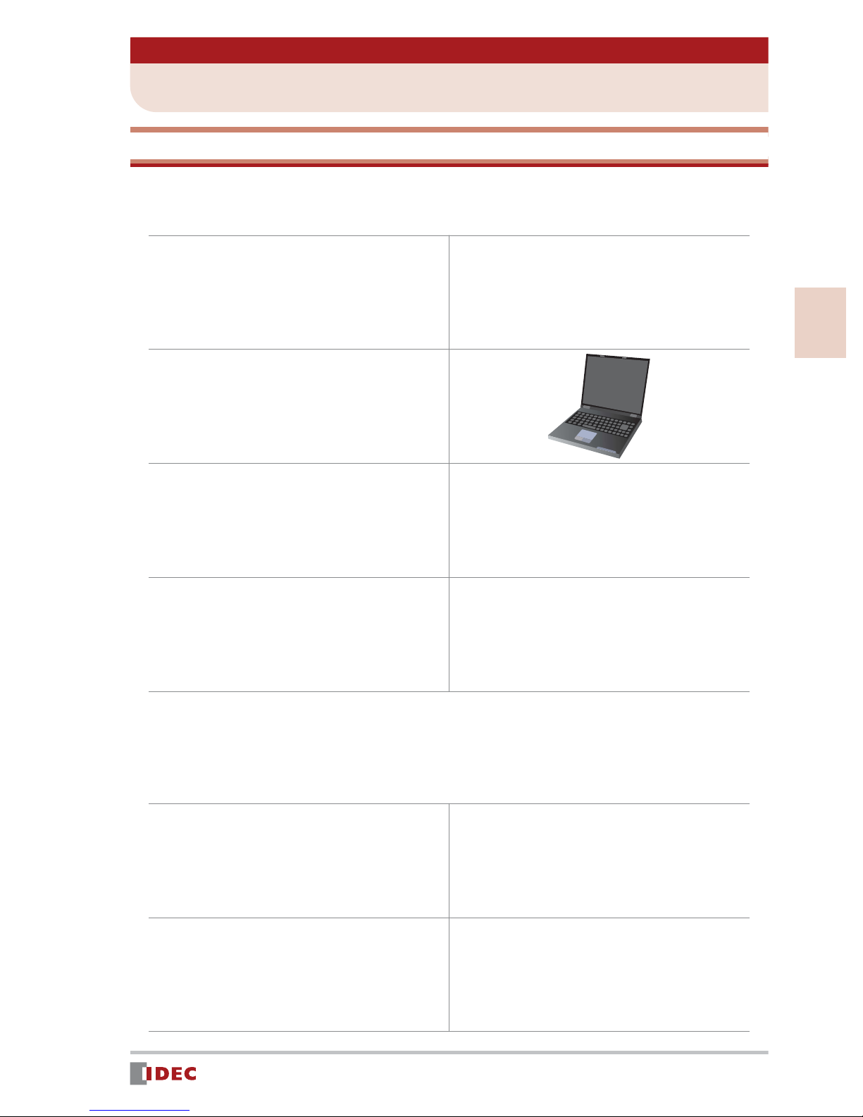
Preparations
Before creating a screen for the OITouchscreen using WindO/I-NV2 software, you will need
the following:
(1) WindO/I-NV2 Software
Part Number: HG9Y-ZSS2W
1
(2) PC
(3)
(4) Operator Interface
If the OI Touchscreen will be configured to communicate with a host (ie. PLC), then you will
also need the following:
*1
To use a PC that does not have a COM
port, use a commercially available
USB-RS232C converter.
Part Number: FC4A-USB
Programming Cable for the
OI Touchscreen
Part Number: HG9Z-XCM1A
or FC2A-KC4C
*2
Example Part Number:
HG2F-SS22VCF
*1: For PC system requirements, refer to page 44 (back cover).
*2: To supply power to the Operator Interface, a 24 V DC power supply is required.
Inroductio
(5) Programmable Controller
(PLC)
Example: MicroSmart
(6) Communication Cable
(between the MicroSmart & OI)
Example: FC4A-KC2CA
www.IDEC.com/software
5
Page 6
Chapter 1 Introduction
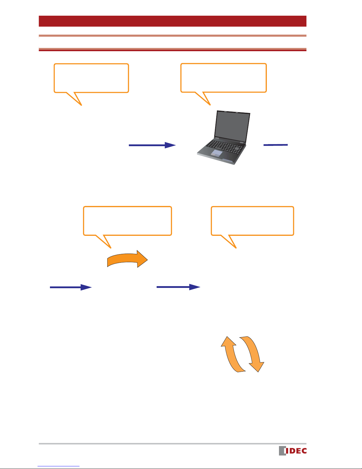
Operation Flow
(1) Software
installation
Refer to Chapter 2 on page 7
Software
WindO/I-NV2
(3)Downloading the project
to the OI
Refer to Chapter 4 on page 34 Refer to Chapter 5 on page 36
(2)Creating a screen
on the PC
Refer to Chapter 3 on page 10
PC
(4)Simulation (operation
verification)
Cable
6
Operator Interface
MicroSmart
www.IDEC.com/software
Page 7
Chapter 2 Installation
1 Software Installation
This section describes the procedure for installing WindO/I-NV2 software.
1.
2.
3.
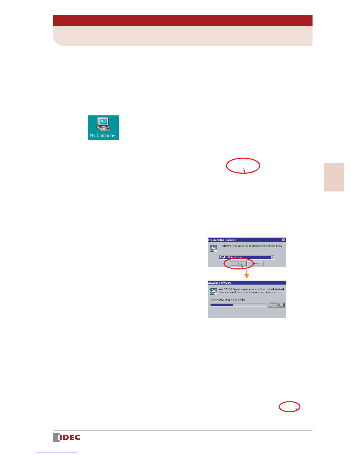
Insert the WindO/I-NV2 CD-ROM into the CD-ROM drive of the PC.
The WindO/I-NV2 setup program will automatically start.
If the setup program does not start:
1. Double-click the My Computer icon on the desktop.
2. Double-click NV2lande.exe in the CD drive.
Click the [WindO/I-NV2 Install] button.
2
4.
5.
Installation
Make sure that English is selected,
and click [OK].
InstallShield Wizard will start.
Click [Next].
www.IDEC.com/software
7
Page 8
Chapter 2 Installation
6.
7.
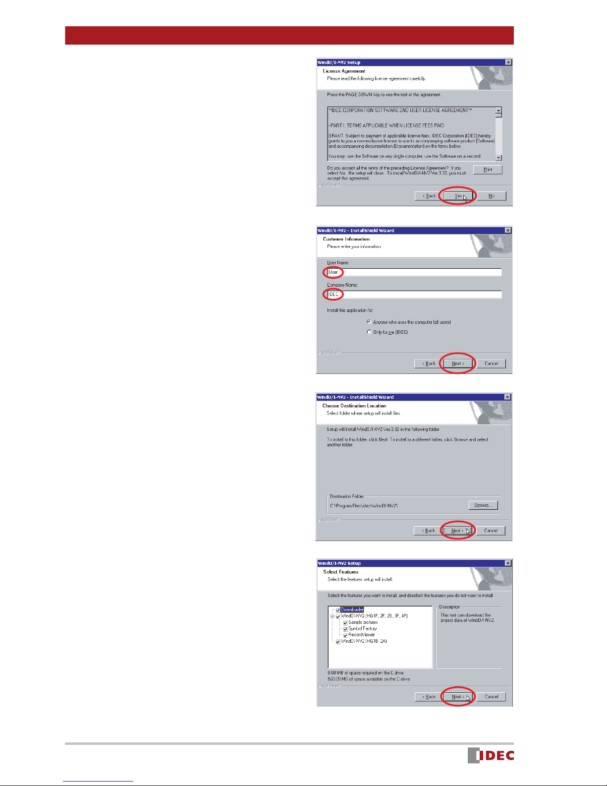
Review the contents of the license
agreement. If you accept the terms
of the agreement, click [Yes].
Enter User Name and Company
Name , and click [Next].
In this example, User and IDEC are
entered in User Name and Company
Name , respectively.
8.
9.
Click [Next].
Click [Next].
8
www.IDEC.com/software
Page 9
Chapter 2 Installation
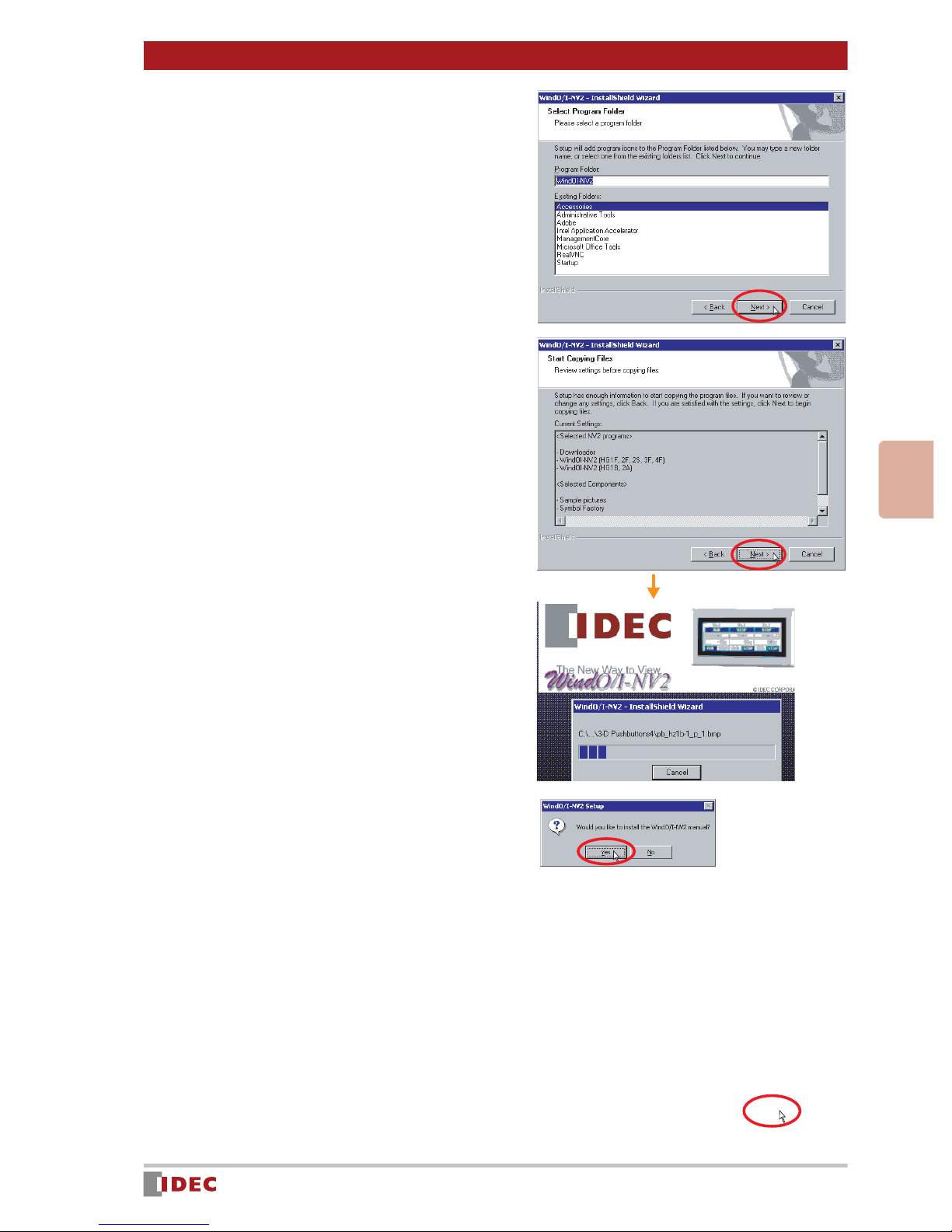
10.
11.
Click [Next].
Review the settings and click
[Next].
2
12.
13.
Installation
Installation will start.
Click [Yes].
After installation is completed,
click [Finish].
www.IDEC.com/software
9
Page 10
Chapter 3 Screen Creation
1 Sample Program
Using WindO/I-NV2 installed in Chapter 2, even beginners can easily create the following
screen:
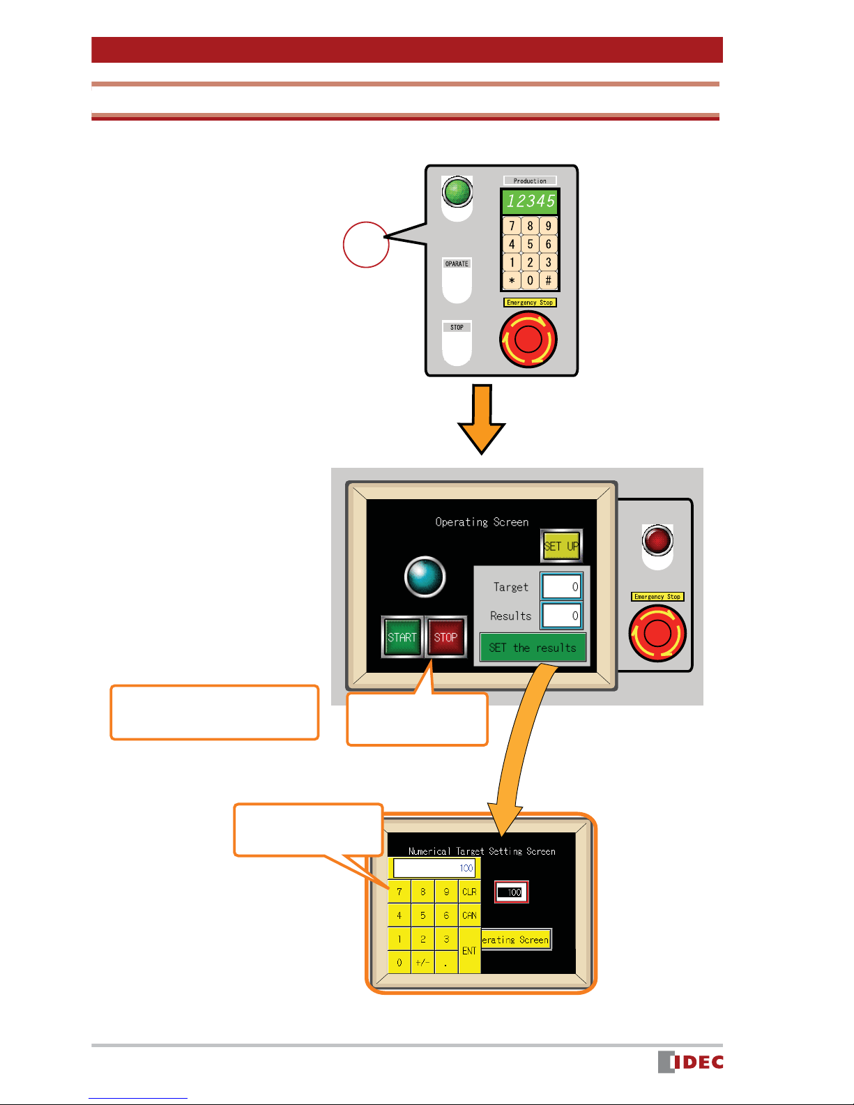
Create a project to control & monitor a product ion line
Using a production line as the application, create a screen that functions as follows:
(1) Starting and stopping the production line using the [START] and [STOP]
buttons
(2) Indicate operation status of the production line with a Pilot Lamp
(3) Entering a target production quantity in Numerical Target , and display-
ing the target quantity in Target
(4) Pressing the [SET the results] button increments the value displayed in
Results by one.
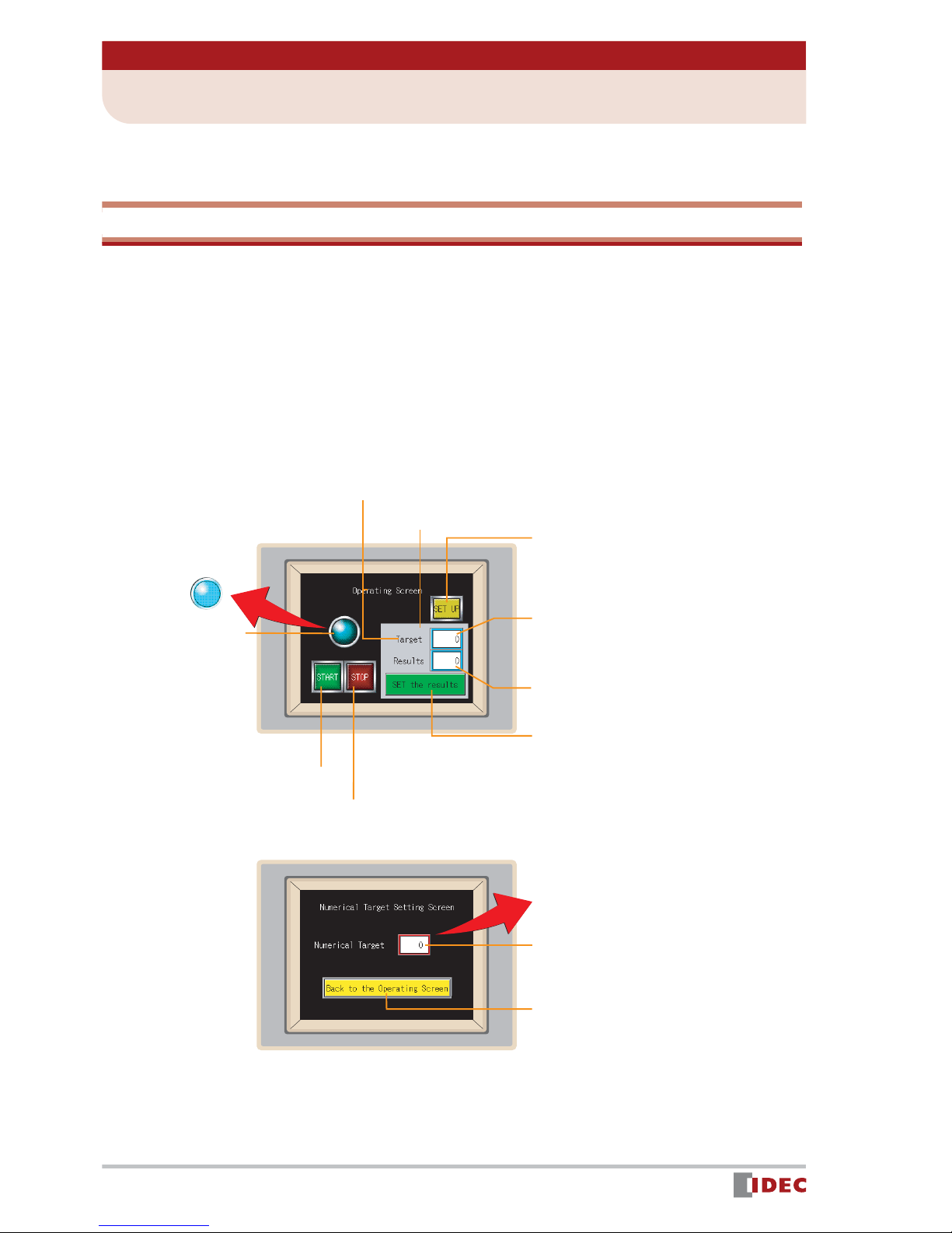
[Operating Screen]
Text: Text to be displayed on
the screen
Rectangle
Pilot Lamp
- When the [START]
button is pressed,
the lamp is ON.
-When the [STOP]
button is pressed,
the lamp is OFF
[START] button
[STOP] button
[Numerical Target Setting Screen]
[SET UP] button:
switches the screen to [Numerical Target
Setting Screen].
Pressing this button
Target: A value entered in the numerical
input field is displayed.
Results: An actual result count is dis-
played.
[SET the results] button:
Pressing this button increments the
value displayed in [Results] by one.
10
www.IDEC.com/software
Numerical input: Pressing this field
displays a numeric input keypad.
[Back to the Operating Screen]
button:
the screen to [Operating Screen].
Pressing this button switches
Page 11
Chapter 3 Screen Creation
0
10
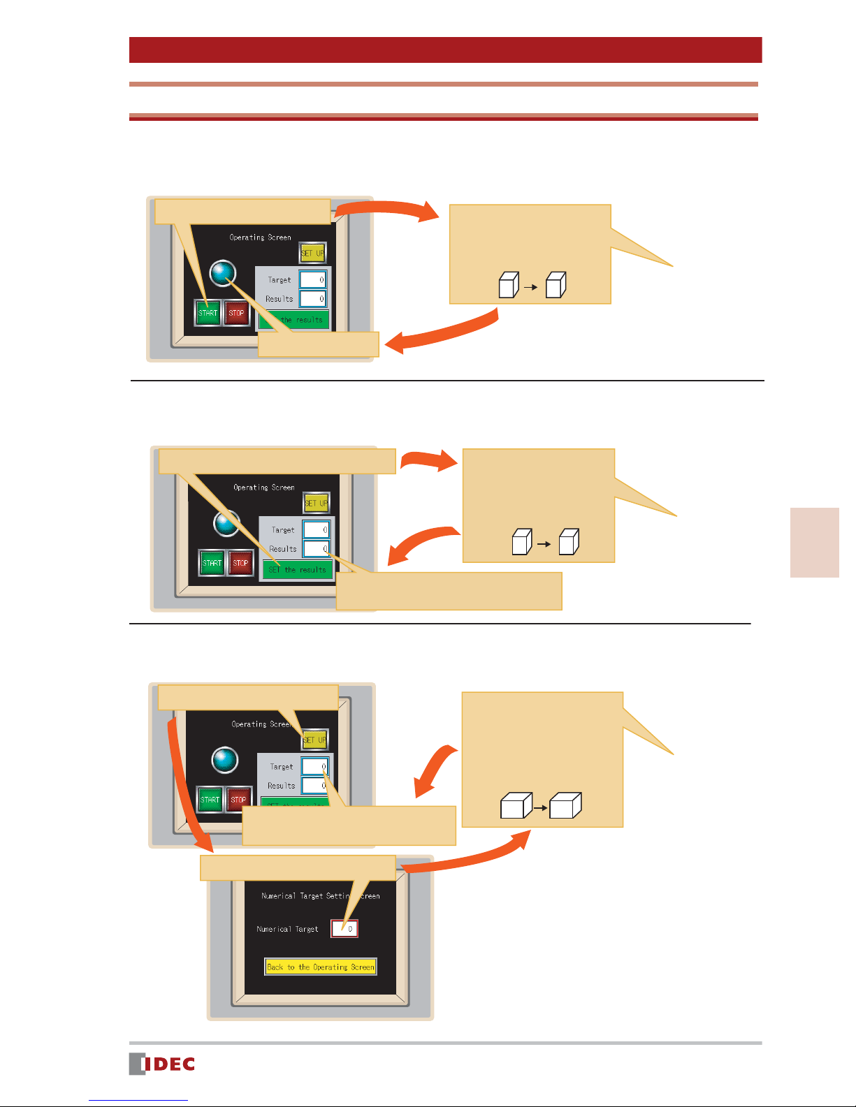
Available Devices and Parts Operation
Each part will be operated with the following devices:
[Q 0]: [START (or [STOP]) button and pilot lamp operation
1. Press the [START] button.
3. Pilot Lamp lights up.
2. Bit 1 is written in device
[Q 0].
Device
[Q 0]
Device
[Q 0]
0 1
[D 10]: [INC the results] button and [Results] display
1. Press the [SET the results] button.
3. The value of device [D 10] is displayed.
2. The value of device [D 10]
is incremented by one.
Device
[D 10]
0 1
Device
[D 10]
3
[D 20]: Numerical input field and [Target] display
1. Press the [SET UP] button.
3. The entered
value is written in
device [D 20].
Device
[D 20]
4. The value of device [D 20] is displayed.
2. Enter a numerical value.
www.IDEC.com/software
Screen Creation
Device
[D 20]
11
Page 12
Chapter 3 Screen Creation
2 Launching WindO/I-NV2 & Creating a New Project
Starting WindO/I-NV2
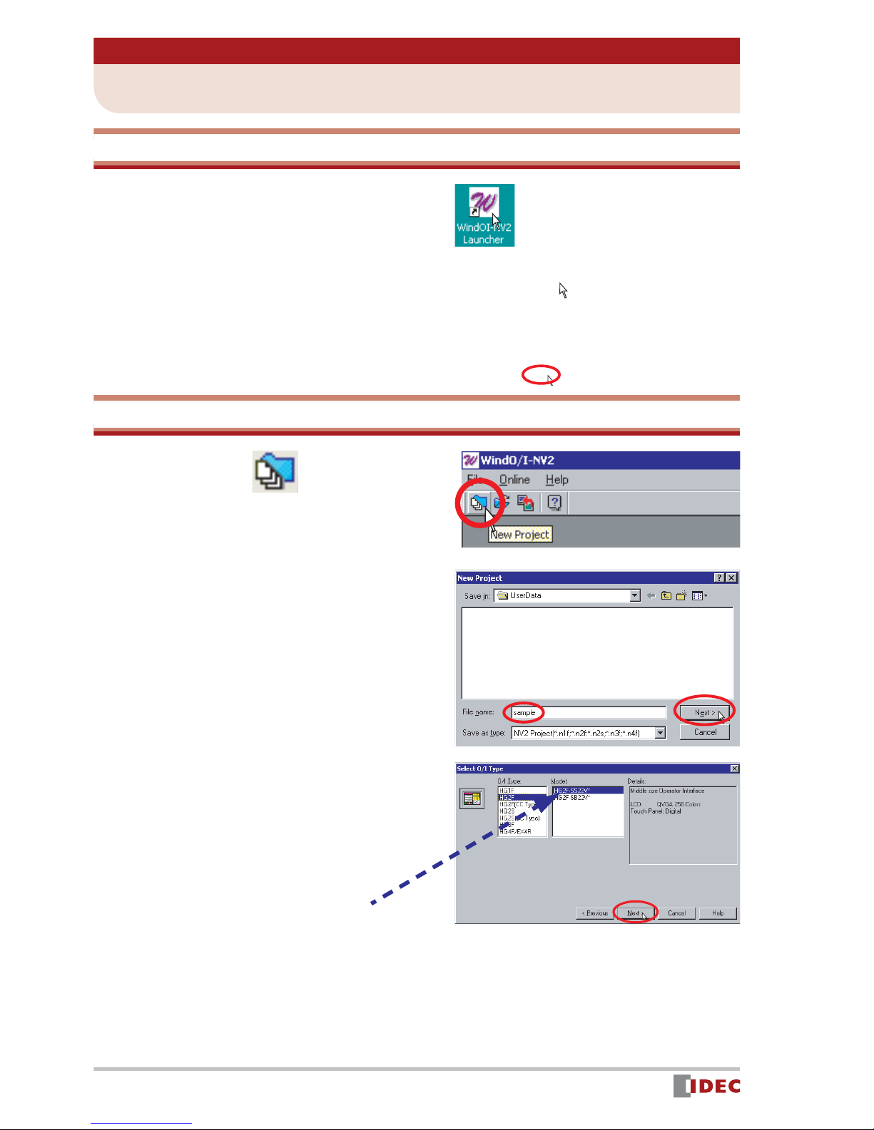
1. Double-click the WindO/I-NV2
Launcher icon on the desktop.
2. Select HG1F/2F/2S/3F/4F .
3. Click [Yes]. WindO/I-NV2 will start.
Creating a New Project
4. Click the (New Project) icon.
5. Enter the file name of a project,
and click [Next].
Enter sample for File name .
6. Select the type and model of the
Operator Interface being used, and
click [Next].
Select HG2F for O/I Type , and select
HG2F-SS22V for Model .
HG2F-SS22VF
12
www.IDEC.com/software
Page 13
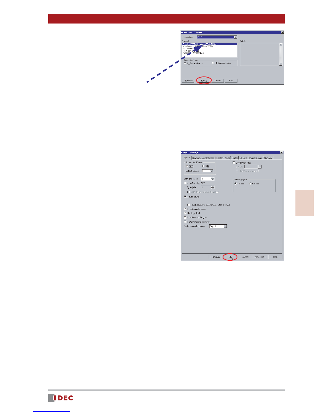
7. Set the items in Select Host I/F
Driver , and click [Next].
Select IDEC for Manufacturer , and
OpenNet (FC3A), MicroSmart (FC4A/
FC5A) for Protocol .
MicroSmart
The Project Settings window will be displayed.
8. Click [OK].
The Project Settings window enables
common settings for all screens of a
project. However, you may keep the
same settings as shown in this window.
Chapter 3 Screen Creation
If you wish to change the settings later,
select [Set up] > [Project Settings]
menu.
Creation of a new project is complete.
The Screen Properties window will be
displayed, and you can proceed to create a screen.
3
Screen Creation
www.IDEC.com/software
13
Page 14
Chapter 3 Screen Creation
3 Creating Screens
[Operating Screen]
Set Up
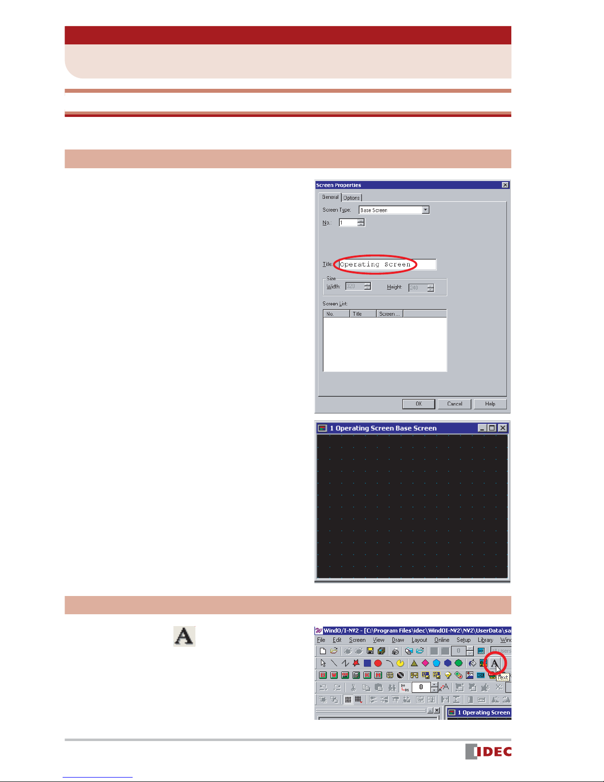
1. Enter [Title]. (optional)
In this example, select Base Screen for
[Screen Type], and enter 1 in [No.].
If you wish to change the above settings,
double-click the screen to display the
Screen Properties window.
2. Click [OK].
The [Operating Screen] setup is complete, and 1 Operating Screen Base
Screen is displayed.
Creating screen text
1. Click the (T ext) icon, and then
click on the screen where you
want the text to be.
The Properties of Text window is displayed.
14
www.IDEC.com/software
Page 15
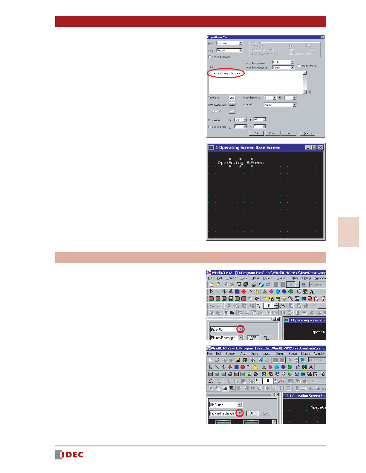
2. Enter Operating Screen in the
text box.
3. Click [OK].
The text will be displayed on the screen.
Chapter 3 Screen Creation
To move the text, use the Drag & Drop
function.
[START] and [STOP] buttons
Create a [START] button and [STOP] button to
turn a Pilot Lamp on/off.
1. To create the [START] and [STOP]
buttons, select Part tab on workspace.
Click [ ] for the parts list and select
2. Click [ ] for shape, and select
Bit Button .
Picture - Rectangle .
3
Screen Creation
www.IDEC.com/software
15
Page 16

Chapter 3 Screen Creation
3. Select the desired part, and place
the part on 1 Operating Screen
Base Screen using drag & drop
operations.
In this example, select Bit Button
sq03_g .
4. Double-click the part placed on the
screen.
The Properties of Bit Button window
is displayed.
5. Click [ ] for Action Mode , and
select Set .
If Set is selected for Action Mode ,
1 will be written in the specified
device when this button is pressed.
6. Enter Q 0 in [Destination
Device].
Insert a space between the letter Q
and the number 0 .
In this example, 1 will be written in
PLC device Q 0 .
7. Select the Registration Text tab,
and enter the text that will appear
on the button.
Q
In this example, enter START .
16
www.IDEC.com/software
Page 17

8. Click the [Color] selection button
to change the text color.
In this example, select 255 (white).
Chapter 3 Screen Creation
9. Click [OK].
The [START] button will appear on the
screen.
10. Create a [STOP] button by follow-
ing the previous steps 1 to 8 as
shown below.
- In Step 1, place Bit Button sq03_r on
the screen.
- In Step 5, select Reset .
(If Reset is selected for Action
Mode , 0 will be written in a specified
device when this button is pressed.)
- In Step 6, enter Q 0.
- In Step 7, enter STOP .
3
Screen Creation
The [STOP] button will appear on the
screen.
www.IDEC.com/software
17
Page 18

Chapter 3 Screen Creation
Pilot Lamp
Create a pilot lamp that will turn on when the [START] button is pressed, and turn off when
the [STOP] button is pressed.
1. T o create a pilot lamp, select Pilot
Lamp .
Click [ ] for the parts list, and select
2. Click [ ] for shape, and select
Pilot Lamp .
Picture - Circle .
3. Click the (Snap to Grid) icon.
The icon is reset (shown as
and the Snap to Grid setting is
disabled.
Disabling Snap to Grid allows you to
place the object/part anywhere on the
screen.
),
4. Select the desired part, and place
the part on 1 Operating Screen
Base Screen using drag & drop
operations.
In this example, select Pilot Lamp
dm13_s .
5. Click the (Snap to Grid) icon.
The Snap to Grid (shown as ),
setting becomes active.
Enabling Snap to Grid allows you to set
the push buttons on a grid so they function properly.
18
www.IDEC.com/software
Page 19

6. Double-click the part placed on the
screen.
The Properties of Pilot Lamp window is
displayed.
7. Select the Trigger Condition tab,
and click [ ] for [Trigger Type].
Select While ON .
If While ON is selected for [Trigger
Type], the lamp will remain lit when the
specified device is ON.
Chapter 3 Screen Creation
8. Enter Q 0 in [Device].
Insert a space between Q and 0 .
In this example, the lamp will be
switched ON/OFF by the PLC device
Q 0 .
9. Click [OK].
Q
3
Screen Creation
www.IDEC.com/software
19
Page 20

Chapter 3 Screen Creation
[SET UP] button
Create a [SET UP] button that will change from [Operating Screen] to [Numerical Target
Setting Screen] when pressed.
1. T o create a [SET UP] button, select
the Goto Screen Button .
Click [ ] for the parts list, and select
2. Click [ ] for shape, and select
Goto Screen Button .
Picture - Rectangle .
3. Select the desired part, and place
the part on 1 Operating Screen
Base Screen using the drag &
drop function.
In this example, select the Goto Screen
Button sq81_y .
4. Double-click the part placed on the
screen.
The Properties of Goto Screen Button
window will be displayed.
20
www.IDEC.com/software
Page 21

Chapter 3 Screen Creation
5. Click [ ] for Action Mode to
select Switch Base Screen .
6. In Goto Screen set Screen No.
to 2 .
The screen No. is set to 2 .
7. Select the Registration Text tab,
and specify the text to be shown
on the button.
In this example, enter SET UP in the
text box.
8. Click the [Color] selection button
to change the text color.
In this example, select 000 (black).
9. Click [OK].
The [Set Up] button will appear on the
screen.
3
Screen Creation
www.IDEC.com/software
21
Page 22

Chapter 3 Screen Creation
[Target] & [Results] Displays
Create a [Target] display to show the value entered in the Numerical Target (numerical
input field). Create a [Results] display that will increment the displayed value by one, every
time the [SET the results] button is pressed.
1. To create the [Target] display,
select Numerical Display .
Click [ ] for the parts list, and select
Numerical Display .
2. Select the desired part, and place
it on 1 Operating Screen Base
Screen using the drag & drop
function.
In this example, select Numerical Display
F0004 .
3. Double-click the part placed on the
screen.
The Properties of Numerical Display
window will be displayed.
4. Enter D 10 in [Display Device].
Insert a space between D and 10 .
In this example, the value of the PLC
device D 10 will be read and displayed
in the [Target].
22
www.IDEC.com/software
Page 23
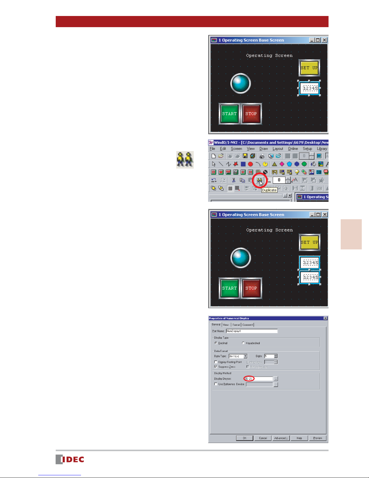
5. Click [OK].
6. Select the numerical display for
the [Target], and click the
(Duplicate) icon.
The numerical display will be copied.
Chapter 3 Screen Creation
7. Drag and drop the copied numeri-
cal display below the [Target]
numerical display.
8. Double-click the duplicated
numerical display, and change the
setting of the Display Device to
D 20 .
Insert a space between D and 20 .
In this example, the value of the PLC
device D 20 will be read and displayed
in [Results].
3
Screen Creation
www.IDEC.com/software
23
Page 24

Chapter 3 Screen Creation
9. Click [OK].
Objects
1. Click the (Rectangle) icon.
2. Click the (Snap to Grid) icon.
The icon is reset (shown as
and the Snap to Grid setting is
disabled.
Disabling Snap to Grid allows you to
place the object/part anywhere on the
screen.
),
3. Click on the screen to start draw-
ing a rectangle.
4. Use the click & drag function to
resize the rectangle if necessary.
24
www.IDEC.com/software
Page 25

5. Double-click the rectangle.
The Properties of Rectangle window
will be displayed.
6. Click the [Fg. Color] selection but-
ton to change the foreground
color.
In this example, select 012 (gray).
Chapter 3 Screen Creation
7. Click the [Palette] selection but-
ton to change the Pattern Palette.
In this example, select Fore 100% .
8. Click [OK].
The completed (rectangle) will appear on
the screen.
3
Screen Creation
9. Place text ( Target and Results )
on the object, following the procedure for Creating text to be displayed on the screen on page 14.
For the text color, select 000 (black).
www.IDEC.com/software
25
Page 26
Chapter 3 Screen Creation
[SET the results] Button
Create a [SET the results] button that will increment the value displayed in [Results] by one,
every time the button is pressed.
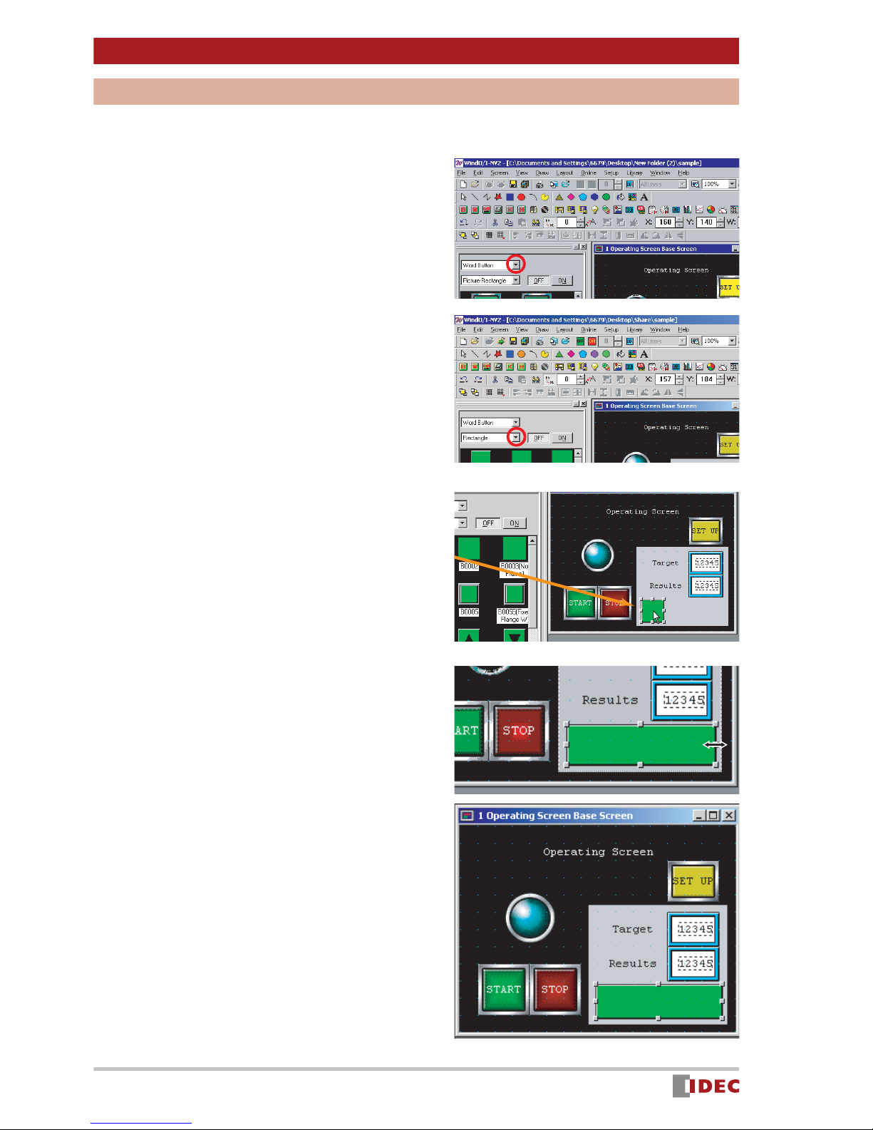
1. To create the [SET the results] but-
ton, select Word Button .
Click [ ] for the parts list, and select
Word Button .
2. Click [ ] for shape, and select
Rectangle .
3. Select the desired part, and place
it on 1 Operating Screen Base
Screen using the drag & drop
function.
In this example, select Word Button
B0001 .
4. Change the size of the part using
the drag & drop function.
5. Double-click the part placed on the
screen.
The Properties of Word Button window
will be displayed.
26
www.IDEC.com/software
Page 27
Chapter 3 Screen Creation
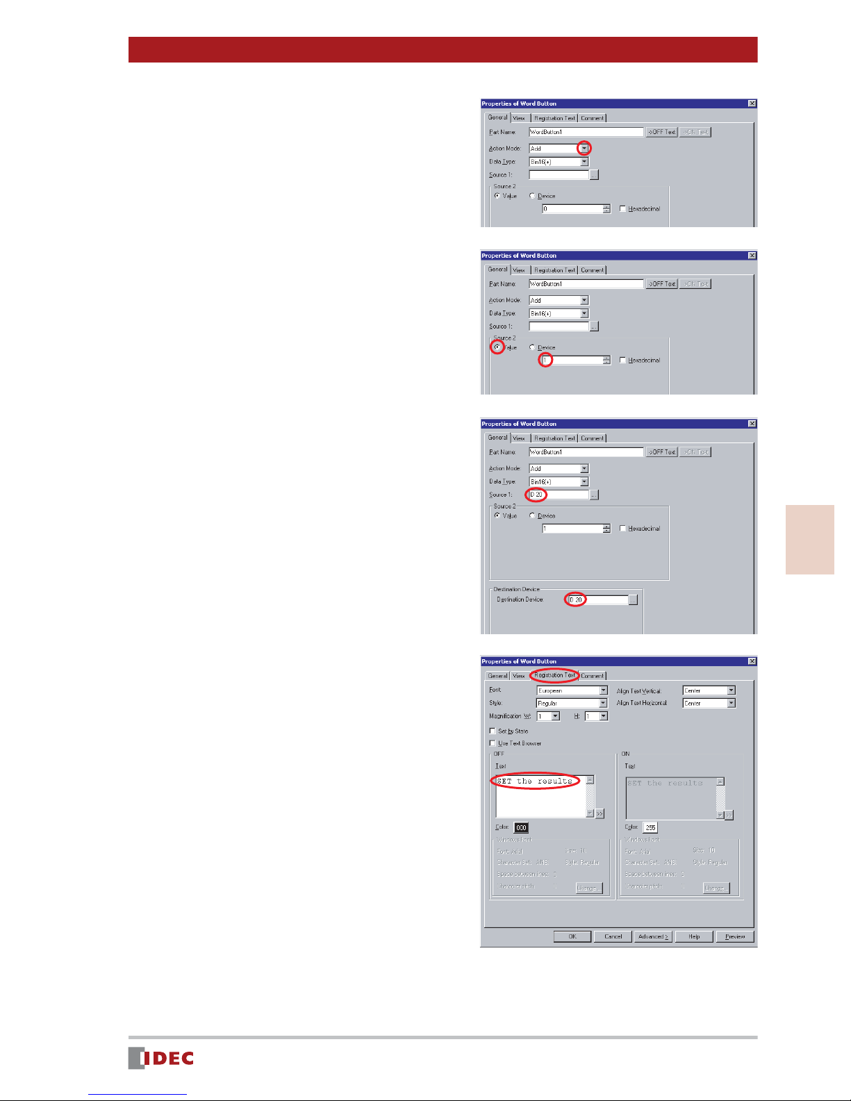
6. Click [ ] for Action Mode , and
select Add .
In this example, select Add , so that the
displayed value will increment.
7. Enter 1 for Value in [Source 2].
In this example, enter 1 for Value so
that the displayed value will increment
by one.
8. Enter D 20 for both [Source 1]
and [Destination Device].
Insert a space between D and 20 .
In this example, the value of the PLC
device D 20 , which is used for the
[Results] display setting, will be read.
The read value will be inceased by one,
and written in D 20 .
3
9. Select the Registration Text tab,
and specify the text to be shown
on the button.
In this example, enter SET the results
in [OFF] - [Text] box.
www.IDEC.com/software
Screen Creation
27
Page 28

Chapter 3 Screen Creation
10. Click [OK].
The [SET the results] button will appear
on the screen
11. Click the (Snap to Grid) icon.
The icon is set (shown as
and the Snap to Grid setting becomes
active.
),
[Numerical Target Setting Screen]
Create a [Numerical Target Setting Screen] to display a screen when the [SET UP] button
is pressed.
Set Up
1. Click the (New Screen) icon.
The Screen Properties window will be
displayed.
28
www.IDEC.com/software
Page 29
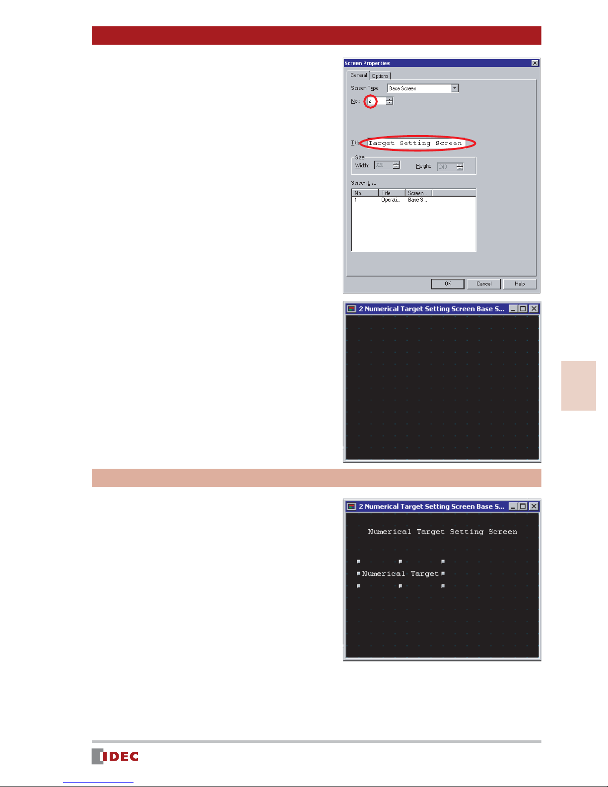
2. Enter 2 in [No.], and enter
Numerical T arget Setting Screen
in [Title].
3. Click [OK].
Chapter 3 Screen Creation
[Numerical Target Setting Screen] set up
is complete, and 2 Numerical Target
Setting Screen Base Screen will be displayed.
Creating screen text
1. Create text for ( Numerical Target
Setting Screen , and Numerical
Target ), according to the procedure for Creating screen text as
described on page 14.
For the text color, select 255 (white).
3
Screen Creation
www.IDEC.com/software
29
Page 30
Chapter 3 Screen Creation
Numerical Target input field
Create a numerical input field to enter and display a target value.
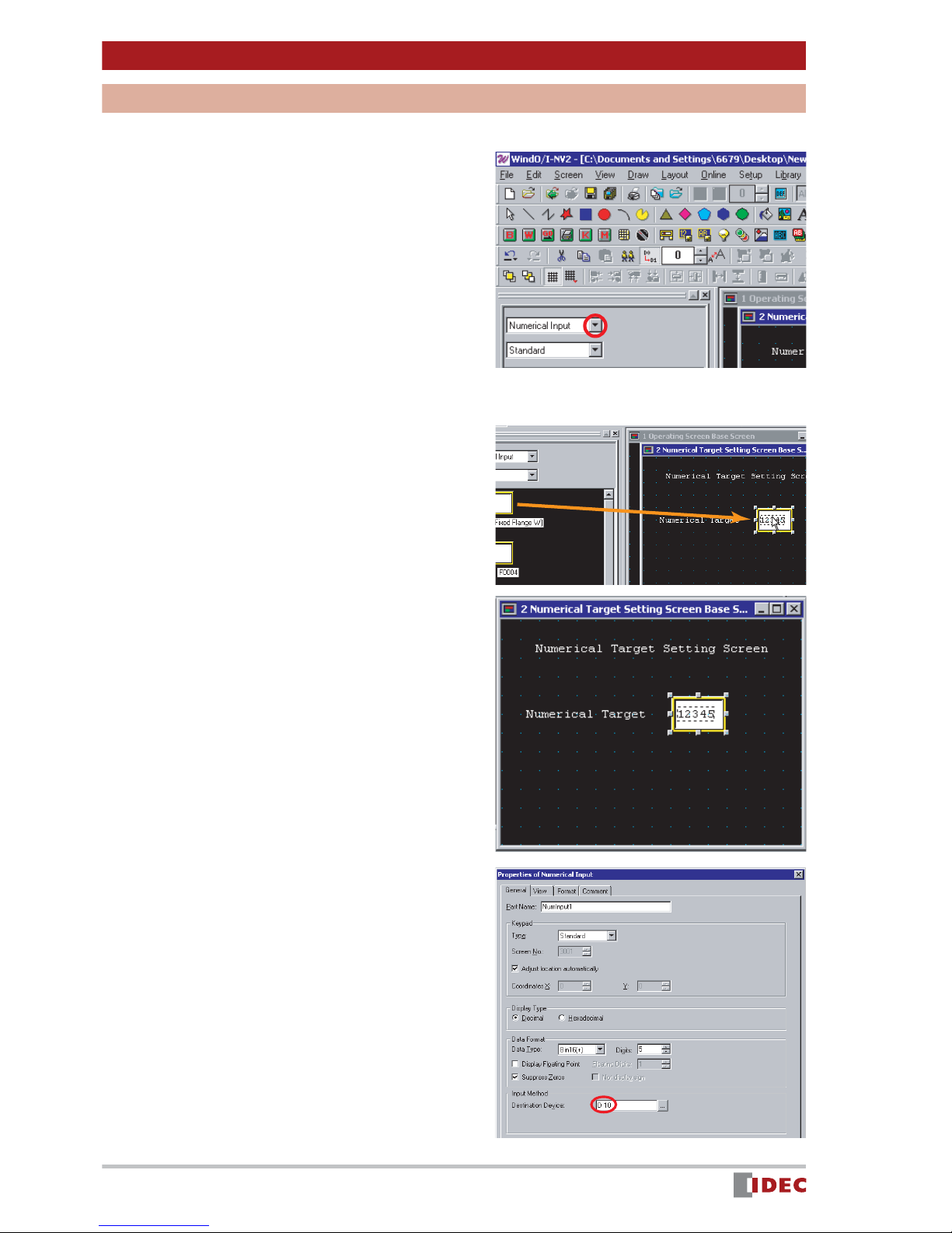
1. To create the Numerical Target
input, select Numerical Input .
Click [ ] for the parts list, and select
Numerical Input .
2. Select the desired part, and place
it on 2 Numerical Target Setting
Screen Base Screen using the
drag & drop function.
In this example, select Numerical Input
F0006 .
3. Double-click the part placed on the
screen.
The Properties of Numerical Input window will be displayed.
4. Enter D 10 in [Destination
Device].
Insert a space between D and 10 .
In this example, the entered value will be
written in PLC device D 10 .
30
www.IDEC.com/software
Page 31
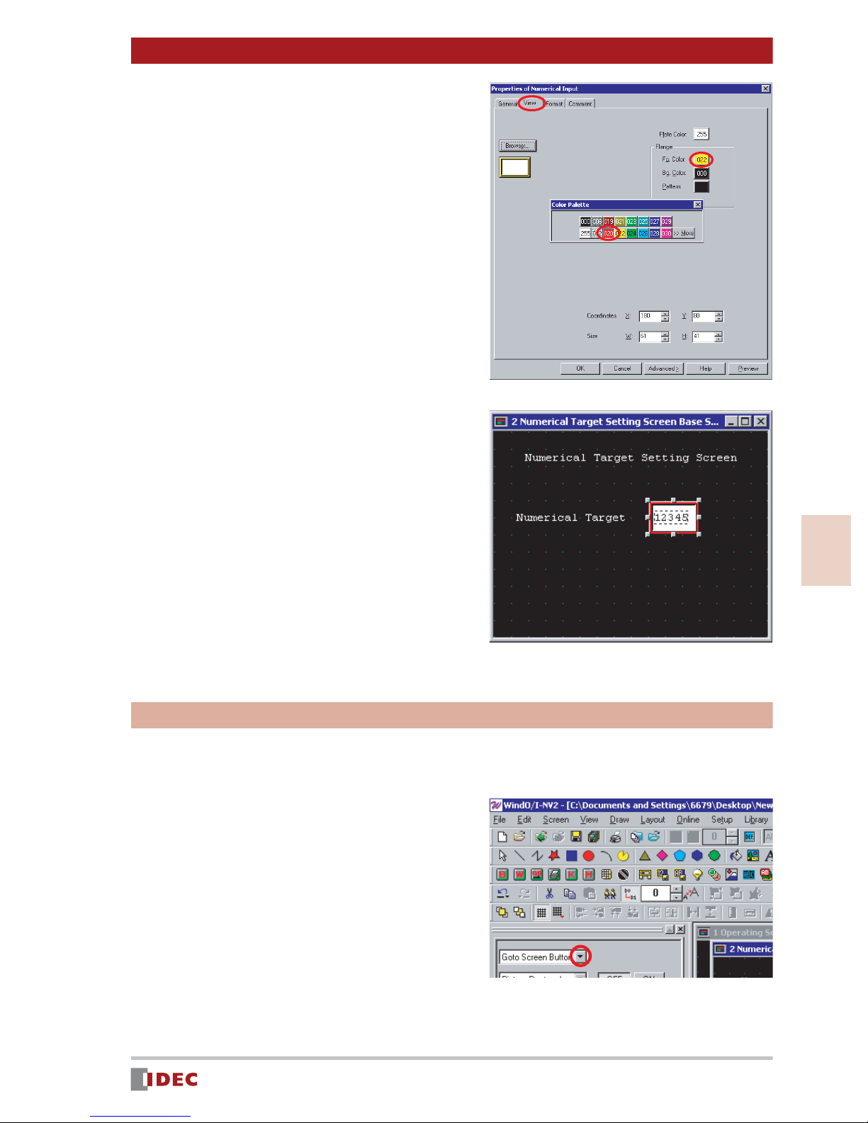
5. Select the [View] tab, and click the
[Fg. Color] selection button in
[Flange] to change the foreground
color.
In this example, select 020 (red) for
[Fg. Color].
Chapter 3 Screen Creation
6. Click [OK].
The numerical input field for the Numerical Target will be displayed on the
screen.
[Back to the Operating Screen] button
Create a [Back to the Operating Screen] button that will switch from the [Numerical Target
Setting Screen] to the [Operating Screen] when pressed.
\
1. To create the [Back to the Operat-
ing Screen] button, select Goto
Screen Button .
3
Screen Creation
Click [ ] for the parts list, and select
Goto Screen Button .
www.IDEC.com/software
31
Page 32

Chapter 3 Screen Creation
2. Click [ ] for shape, and select
Rectangle .
3. Select the desired part, and place
it on 2 Numerical Target Setting
Screen Base Screen using the
drag & drop function.
In this example, select Goto Screen Button B0055 (Fixed Flange W) .
4. Change the size of the part using
the click & drag function.
5. Double-click the part placed on the
screen.
The Properties of Goto Screen Button
window will be displayed.
6. Click [ ] for Action Mode , and
select Switch Base Screen .
7. In [Goto Screen] set [Screen No.]
to 1 .
In this example, set the screen No. to 1
because the [Opeating Screen] No. or
the screen to be switched to, is 1 .
32
www.IDEC.com/software
Page 33

8. Select the [View] tab, and click the
[Fg. Color] selection button in
[OFF] to change the foreground
color.
In this example, select 022 (yellow) for
[OFF] - [Fg. Color].
9. Select the Registration Text tab
and enter the text to be shown on
the button.
In this example, enter Back to the Operating Screen .
Chapter 3 Screen Creation
10. Click [OK].
[Back to the Operating Screen] button is
will be displayed.
Saving
Click the (Save Project) icon.
3
Screen Creation
www.IDEC.com/software
33
Page 34

Chapter 4 Download
1 Downloading the Project
If you download the project data created in Chapter 3 to an Operator Interface, the project
will be displayed and can be operated on the OI screen.
1. Connect the Operator Interface to
a PC with a cable.
Cable for connecting PC to Operator Interface
(HG9Z-XCM1A or FC2A-KC4C)
2. Click the (Download Project) icon.
3. Click [Download].
The Operator Interface starts downloading the project.
Connect the cable to the maintenance
communication interface.
Connect the cable to the RS232C port.
4. After the download confirmation
message appears, click [Yes].
34
www.IDEC.com/software
Page 35

5. After download is complete, click
[OK].
6. Click [Close].
Chapter 4 Download
If download cannot be completed, check the following:
- Check the power supply to the Operator Interface.
- Check the cable connection between the Operator Interface and the PC.
- Check the COM port of the PC connected to the Operator Interface.
* If the COM port is being used by another application, then the port is not available for
download.
Host Communication Error
Once a project is downloaded to the Operator Interface, the Operator Interface may display
a Host Communication Err message after approx. 10 seconds.
This error is caused by improper connection
between the Operator Interface and the PLC that
the Operator Interface is to communicate with.
Even if the Host Communication Err message is
displayed, the Operator Interface can execute offline operation checks using the simulation function. (Refer to Simulation Mode on page 36.)
HostCommunicationerr
4
Download
www.IDEC.com/software
35
Page 36

Chapter 5 Verify Operation
1 Simulation Mode
Running Simulation Mode will verify whether the downloaded project data is displayed correctly and if it will function properly on the Operator Interface.
Starting Simulation Mode
The IDEC OI Touchscreens have a simulation mode that enables the Operator Interface to
check the functionality of the project without being connected to a PLC.
1. Simultaneously press the top right
and top left corners on the screen
for 3 seconds.
The Maintenance screen appears.
HostCommunicationerr
2. Press the [System Mode] button.
The Main Menu screen appears.
3. Press the [Debug] button.
The Debug screen appears.
4. Press the [Simulat n] button.
0DLQWHQDQFH
6\VWHP0RGH
'HYLFH0RQLWRU
$GMXVW&RPWUDVW
0DLQ0HQX
,QLWLDO
6HWWLQJ
6HOI
'LDJQRVLV
6\VWHP
,QIRUPDWLRQ
Fri4/04/200812:00:01
0DLQ0HQX 'HEXJ
6LPXODWQ
(1*-31
&ORFN6HW
'HEXJ
5XQ6WDUW
5. Press the [Start] button.
The project [Operating Screen] is displayed, and simulation is enabled.
( Simulation Mode will blink at the bottom left of the screen.)
36
www.IDEC.com/software
0DLQ0HQX 'HEXJ
<RXFDQGHEXJXVLQJRQO\2,
ZLWKRXW3/&
6WDUW
6LPXODWQ
Page 37

Simulating
1. Press the [START] button.
The pilot lamp turns on.
2. Press the [STOP] button.
The pilot lamp turns off.
3. Press the [SET UP] button.
The [Numerical Target Setting Screen]
appears.
Chapter 5 Verify Operation
4. Press the Numerical input.
The numeric keypad appears.
5. Enter 100 , and press the [ENT]
key.
100 is set in [Numerical Target].
6. Press the [Back to the Operating
Screen] button.
The [Operating Screen] appears, and
100 is displayed in [Target].
7. Press the [SET the results] button.
5
Every time this button is pressed, the
value displayed in [Results] increments
by one.
www.IDEC.com/software
Verify Operation
37
Page 38

Chapter 5 Verify Operation
2 Debug Mode
If the Operator Interface does not operate normally when connected to a PLC, you can
check and correct the settings, while monitoring operations with WindO/I-NV2.
Start Debug Mode
The process for detecting and correcting errors in project data is called Debug .
WindO/I-NV2 software provides a debug function (debugger).
Cable for connecting PC to Operator Interface
(HG9Z-XCM1A or FC2A-KC4C)
Connect the cable to the maintenance
1. Connect the Operator Interface to
a PC with a cable.
communication interface.
Connect the cable to the RS232C port.
2. Click the [Online] menu.
3. Click the [Start Debug] menu.
The Operator Interface displays the
screen monitor window and the debug
tool bar, and starts debugging.
In this step, the monitor window displays
information on the [Operating Screen].
38
www.IDEC.com/software
Page 39

Chapter 5 Verify Operation
Verify Operation with the Screen Monitor
The screen monitor allows you to verify actual screen operation and automatically display
all devices being used for the target screen. You can also view the data values or change
the data value of each device used.
If the screen monitor is not displayed, click the (Screen
Monitor) icon.
Checking pilot lamp operation on [Operating Screen]
1. Double-click Value for device
address Q 0 .
Up and down buttons are displayed.
2. Click [ ] to set the value to 1 ,
and press [Enter].
The pilot lamp on the Operator Interface
will turn on.
If the pilot lamp does not turn on,
check the device for the lamp.
(Refer to "Pilot Lamp" on page 18.)
Q
Q
5
www.IDEC.com/software
Verify Operation
39
Page 40

Chapter 5 Verify Operation
Verifying [Target] and [Results] Values on [Operating Screen]
1. Double-click the Value cell for
device address D 10 .
Up and down buttons are displayed.
Q
2. Click [ ] to set the value and
press [Enter].
In this example, the value is set to 5 .
The value will be displayed in the [Tar-
get] numerical display on the Operator
Interface.
3. Repeat Steps 1 and 2 to check
device address D 20 .
The value will be displayed in the
[Results] display on the Operator Interface.
If the value is not shown in each numerical display, check the device for
the numerical display [Target] or [Results] .
(Refer to "[Target] & [Results] Displays" on page 22.)
Q
Q
Verifying [Numerical Target] on [Numerical Target Setting Screen]
1. Click (Next Screen) button.
[Screen Monitor - 2 Numerical Target
Setting Screen Base Screen] appears.
The [Numerical Target Setting Screen] is
displayed on the Operator Interface.
40
Q
www.IDEC.com/software
Page 41

2. Double-click the Value cell for
device address D 10 .
Up and down buttons are displayed.
Chapter 5 Verify Operation
3. Click [ ] to set the value and
press [Enter].
In this example, the value is 5 .
The value will be displayed in the
[Numerical Target] numerical input field
on the Operator Interface.
If the value does not display in the numerical input field, check the
devices for the [Numerical Target] numerical input field.
(Refer to " Numerical Target input field" on page 30.)
End Debugging Mode
Once debugging is complete, exit debug mode.
Click the (Stop Debugging) icon.
www.IDEC.com/software
5
Verify Operation
41
Page 42
Chapter 6 Appendix
1 Tools and Functions
Shortcut Keys
Using keyboard shortcuts, you can execute frequently used operations.
Edit
Undo Ctrl + Z
Redo Ctrl + Y
Cut Ctrl + X
Copy Ctrl + C
Paste Ctrl + V
Duplicate Ctrl + D
Screen
New Screen Ctrl + N
Open Screen Ctrl + O
Open Previous
Screen
Open Next
Screen
Save Screen Ctrl + S
Ctrl + R
Ctrl + E
Others
Snap to Grid F8
Download F9
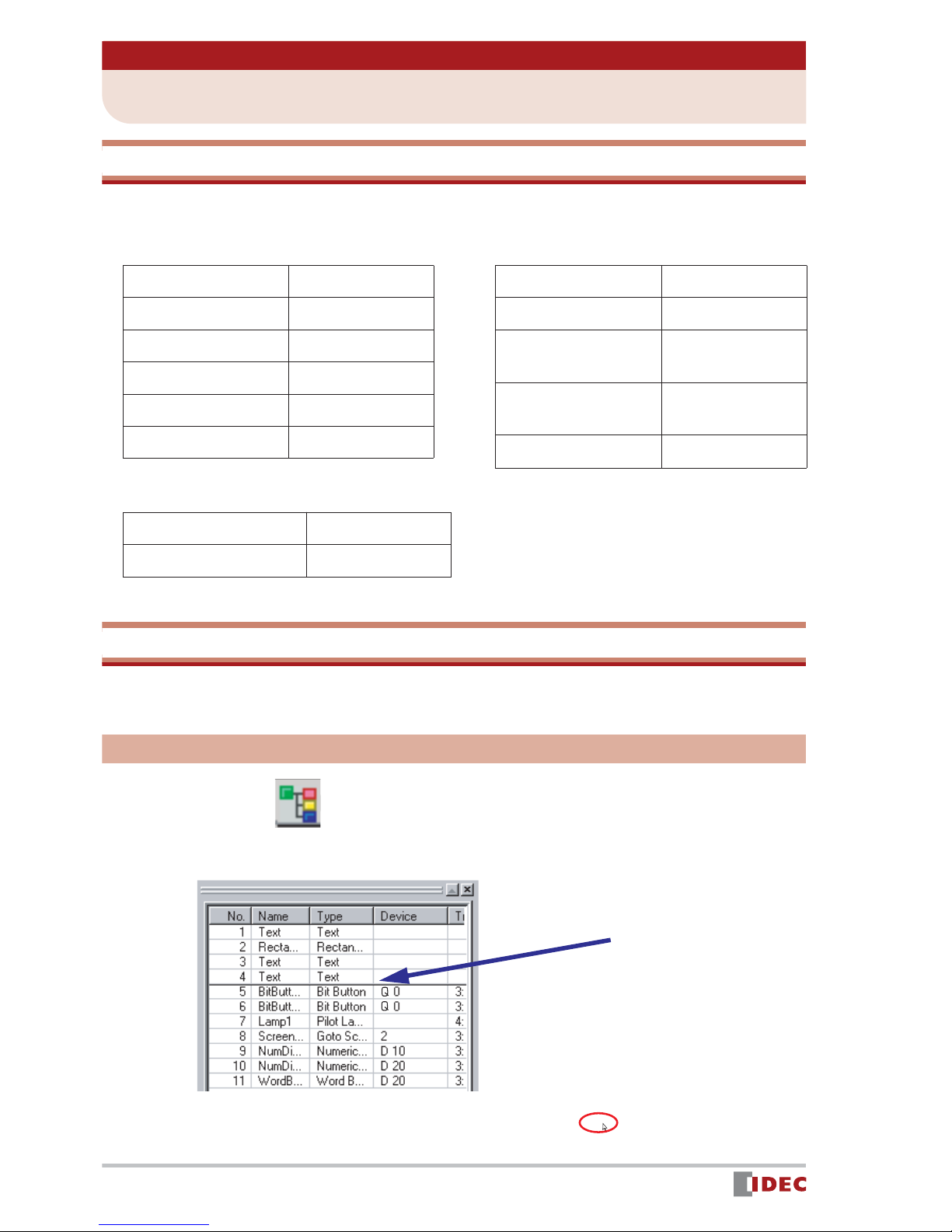
Object List
The Object List displays a list of parts and objects that have been placed on a screen. You
can easily change the properties of the listed parts.
Displaying an object list
Click the (Object ) button at the bottom of the workspace.
42
www.IDEC.com/software
Page 43
Changing objects in the workspace
Click the cell you want to change and
press [F2] or [F3] on the keyboard.
You can change a destination device through
direct input on the keyboard.
Changing properties
Double-click the No. , Name or Type
cell.
Chapter 6Appendix
The Properties window appears.
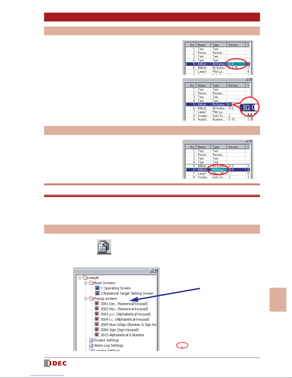
Project List
The Project List enables overall project management. It displays a list of screens and
related settings that have been saved for a particular project allowing you to easily change
their properties.
Displaying a project list
Click the (Project) button at the
bottom of the workspace.
www.IDEC.com/software
6
Appendix
43
Page 44

System Requirements
Compatible PC PC-AT compatible model
Compatible OS
Windows 95 (OSR2 or later version)/98/Me/NT4.0/2000/XP/Vista
(Incompatible with 64-bit version)
CPU CPU that normally runs Windows (Pentium, 200 MHz or higher)
RAM 64MB minimum
Hard Disk Empty area: 150MB minimum (including manual)
Graphic SVGA (800 x 600) or higher resolution
User
User authorized as administrator (for use of Windows NT4.0/2000/
XP/Vista)
Others Mouse, CD-ROM drive, COM port
Operator Interface Models
Model
Type HG4F HG3F
Screen Size 12.1 inches 10.4 inches 5.7 inches 5.7 inches
Appearance
Large Medium Small CC Pendant
HG2F
(Color)
HG2F
(Monochrome)
HG1F
(Monochrome)
HG2S
(Color)
(Monochrome)
4.6 inches 5.7 inches 5.7 inches
HG2S
LCD
Pixels
Display Color
User Memory Size
Memory Card (CF)
Ethernet Port
O/I Link
USB
RS232C
RS485/422
UL
CSA (c-UL)
CE
USA
IDEC Corporation
Tel (408) 747-0550
opencontact@idec.com
Canada
IDEC Canada Ltd.
Tel (905) 890-8561
sales@ca.idec.com
Australia
IDEC Australia Pty . Ltd.
Tel +61-3-9763-3244
sales@au.idec.com
TFT
800 × 600
256 colors
6 MB
Yes
Yes
Yes
—
Yes
Yes
Yes
Yes
Yes
TFT
640 × 480
256 colors
6 MB
Yes
Yes
Yes
—
Yes
Yes
Yes
Yes
Yes
Japan
IDEC Corporation
Tel +81-6-6398-2571
products@idec.co.jp
United Kingdom
IDEC Electronics Ltd.
Tel +44 (0) 1256-321000
sales@uk.idec.com
Specifications and other descriptions in this catalog are subject to change without notice.
STN
320 × 240
256 colors
2 MB
Yes
—
Yes
Yes
Yes
Yes
Yes
Yes
Yes
STN
320 × 240
Monochrome
2 MB
Yes
—
Yes
Yes
Yes
Yes
Yes
Yes
Yes
2VN-I/OdniWDesign T ool
www.idec.com
Germany
IDEC Elektrotechnik GmbH
Tel: +49-40-253054-0
service@idec.de
Hong Kong
IDEC (H.K.) Co., Ltd.
Tel +852-2803-8989
info@hk.idec.com
©2007 IDEC Corporation. All Rights Reserved
www.idec.com
STN
300 × 100
Monochrome
1 MB
—
—
Yes
—
Yes
Yes
Yes
Yes
Yes
China/Beijing
IDEC (Shanghai) Corporation
Tel +86-10-6581-6131
idec@cn.idec.com
China/Shanghai
IDEC IZUMI (Shanghai) Co., Ltd.
Tel: +86-21-5353-1000
idec@cn.idec.com
STN
320 × 240
256 colors
2 MB
—
—
Yes
—
Yes
Yes
Yes
Yes
Yes
China/Shenzhen
IDEC (Shenzhen) Corproation
Tel: +86-755-8356-2977
Singapore
IDEC Asia Pte. Ltd.
Tel +65-6746-1155
info@sg.idec.com
Taiwan
IDEC Taiwan Corporation
Tel: +886-2-2698-3929
service@idectwn.com.tw
STN
320 × 240
Monochrome
2 MB
—
—
Yes
—
Yes
Yes
Yes
Yes
Yes
WindO/I-NV2 Ver.3.3 07-391-082
 Loading...