

Page 1

T
utorial
for
HG2F/3F/4F Series Operator Interfaces
Page 2

W
ind
O/I-NV2
T
utorial
for HG2F/3F/4F Series Operator Interfaces
English Edition 3.0
July 2004
IDEC Corporation
1
175 Elko Drive
Sunnyvale, CA
Ph: 800-262-IDEC
Fax: 800-635-6246
www
94089
.idec.com
Page 3

1
How to Use WindO/I-NV2
1.1 Starting WindO/I-NV2
1.2 Creating Data
1.2.1
1.2.2
1.2.3
1.3 Editing Data
1.3.1
1.3.2
1.3.3
1.3.4
1.3.5
1.3.6
1.3.7
1.3.8
1.4 Saving Data
1.4.1
1.4.2
1.4.3
1.4.4
1.5 Setting Conditions
1.5.1
1.5.2
1.5.3
1.5.4
1.5.5
1.5.6
1.5.7
1.5.8
1.6 Logging Data
1.6.1
1.6.2
1.7 Using Recipe Data
1.8 Exiting WindO/I-NV2
. . . . . . . . . . . . . . . . . . . . . . . . . . . . . . . . . . . . . . . . . . . . . . . . . . . . . . . . . . . . .1-1
Creating a Project
Creating a Base Screen
Creating a Popup Screen
. . . . . . . . . . . . . . . . . . . . . . . . . . . . . . . . . . . . . . . . . . . . . . . . . . . . . . . . . . . . . . .1-6
Editing a Project
Editing Screens
Duplicating Screens
Importing Screens
Deleting Screens
Changing Screen Number
Changing O/I Type
Changing Host I/F Driver
. . . . . . . . . . . . . . . . . . . . . . . . . . . . . . . . . . . . . . . . . . . . . . . . . . . . . . . . . . . . . .1-15
Saving a Project
Saving a Project With a New Name
Saving Multiple Screens
Saving a Screen With a New Number
Setting an Operation
Selecting a Mode
Setting a Default Path
Automatically Adjusting an Address
Automatically Saving Data
Changing the Displayed Font
Displaying Screens as Thumbnails
Displaying Object List
. . . . . . . . . . . . . . . . . . . . . . . . . . . . . . . . . . . . . . . . . . . . . . . . . . . . . . . . . . . . .1-25
Setting Alarm Logging Data
Setting Trend Logging Data
. . . . . . . . . . . . . . . . . . . . . . . . . . . . . . . . . . . . . . . . . . . . . . . . . . . . . . .1-1
. . . . . . . . . . . . . . . . . . . . . . . . . . . . . . . . . . . . . . . . . . . . . . . . . . . . . . . . .1-17
. . . . . . . . . . . . . . . . . . . . . . . . . . . . . . . . . . . . . . . . . . . . . . . . . . . . . . . . .1-34
. . . . . . . . . . . . . . . . . . . . . . . . . . . . . . . . . . . . . . . . . . . . . . . . . . . . . . .1-40
T
able of Contents
. . . . . . . . . . . . . . . . . . . . . . . . . . . . . . . . . . . . . . . . . . . . . . . . . . . .1-1
. . . . . . . . . . . . . . . . . . . . . . . . . . . . . . . . . . . . . . . . . . . . . . .1-3
. . . . . . . . . . . . . . . . . . . . . . . . . . . . . . . . . . . . . . . . . . . . . .1-4
. . . . . . . . . . . . . . . . . . . . . . . . . . . . . . . . . . . . . . . . . . . . . . . . . . . . .1-6
. . . . . . . . . . . . . . . . . . . . . . . . . . . . . . . . . . . . . . . . . . . . . . . . . . . . .1-7
. . . . . . . . . . . . . . . . . . . . . . . . . . . . . . . . . . . . . . . . . . . . . . . . . .1-8
. . . . . . . . . . . . . . . . . . . . . . . . . . . . . . . . . . . . . . . . . . . . . . . . . . .1-9
. . . . . . . . . . . . . . . . . . . . . . . . . . . . . . . . . . . . . . . . . . . . . . . . . . .1-11
. . . . . . . . . . . . . . . . . . . . . . . . . . . . . . . . . . . . . . . . . . . .1-12
. . . . . . . . . . . . . . . . . . . . . . . . . . . . . . . . . . . . . . . . . . . . . . . . . .1-13
. . . . . . . . . . . . . . . . . . . . . . . . . . . . . . . . . . . . . . . . . . . . .1-14
. . . . . . . . . . . . . . . . . . . . . . . . . . . . . . . . . . . . . . . . . . . . . . . . . . . .1-15
. . . . . . . . . . . . . . . . . . . . . . . . . . . . . . . . . . . . .1-15
. . . . . . . . . . . . . . . . . . . . . . . . . . . . . . . . . . . . . . . . . . . . . .1-15
. . . . . . . . . . . . . . . . . . . . . . . . . . . . . . . . . . .1-16
. . . . . . . . . . . . . . . . . . . . . . . . . . . . . . . . . . . . . . . . . . . . . . . . .1-17
. . . . . . . . . . . . . . . . . . . . . . . . . . . . . . . . . . . . . . . . . . . . . . . . . . .1-18
. . . . . . . . . . . . . . . . . . . . . . . . . . . . . . . . . . . . . . . . . . . . . . . .1-19
. . . . . . . . . . . . . . . . . . . . . . . . . . . . . . . . . . . . .1-19
. . . . . . . . . . . . . . . . . . . . . . . . . . . . . . . . . . . . . . . . . . . .1-21
. . . . . . . . . . . . . . . . . . . . . . . . . . . . . . . . . . . . . . . . . .1-22
. . . . . . . . . . . . . . . . . . . . . . . . . . . . . . . . . . . . .1-23
. . . . . . . . . . . . . . . . . . . . . . . . . . . . . . . . . . . . . . . . . . . . . . . .1-24
. . . . . . . . . . . . . . . . . . . . . . . . . . . . . . . . . . . . . . . . . . .1-25
. . . . . . . . . . . . . . . . . . . . . . . . . . . . . . . . . . . . . . . . . . .1-30
i
Page 4

Table of Contents
2
How to Use Objects
2.1 Drawing
2.2 Setting Appearances & Trigger Condition . . . . . . . . . . . . . . . . . . . . . . . . . . . . . . . . . . . . . . . 2-16
2.3 Writing to a Device . . . . . . . . . . . . . . . . . . . . . . . . . . . . . . . . . . . . . . . . . . . . . . . . . . . . . . . . . 2-31
. . . . . . . . . . . . . . . . . . . . . . . . . . . . . . . . . . . . . . . . . . . . . . . . . . . . . . . . . . . . . . . . . .2-1
2.1.1
Drawing a Line
2.1.2
Changing Line Properties
2.1.3
Drawing a Polyline
2.1.4 Changing Polyline Properties . . . . . . . . . . . . . . . . . . . . . . . . . . . . . . . . . . . . . . . . . . . 2-3
2.1.5 Adding Apexes to a Polyline . . . . . . . . . . . . . . . . . . . . . . . . . . . . . . . . . . . . . . . . . . . . 2-3
2.1.6 Modifying Apex Location on a Polyline . . . . . . . . . . . . . . . . . . . . . . . . . . . . . . . . . . . . 2-4
2.1.7 Drawing a Polygon . . . . . . . . . . . . . . . . . . . . . . . . . . . . . . . . . . . . . . . . . . . . . . . . . . . 2-5
2.1.8 Changing Polygon Properties . . . . . . . . . . . . . . . . . . . . . . . . . . . . . . . . . . . . . . . . . . . 2-6
2.1.9 Adding Apexes to a Polygon . . . . . . . . . . . . . . . . . . . . . . . . . . . . . . . . . . . . . . . . . . . . 2-6
2.1.10 Modifying Apex Location on a Polygon . . . . . . . . . . . . . . . . . . . . . . . . . . . . . . . . . . . 2-7
2.1.11 Drawing a Rectangle . . . . . . . . . . . . . . . . . . . . . . . . . . . . . . . . . . . . . . . . . . . . . . . . . 2-8
2.1.12 Changing Rectangle Properties . . . . . . . . . . . . . . . . . . . . . . . . . . . . . . . . . . . . . . . . 2-8
2.1.13 Drawing a Circle or an Ellipse . . . . . . . . . . . . . . . . . . . . . . . . . . . . . . . . . . . . . . . . . . 2-9
2.1.14 Changing the Properties of a Circle or an Ellipse . . . . . . . . . . . . . . . . . . . . . . . . . . 2-10
2.1.15 Drawing an Arc . . . . . . . . . . . . . . . . . . . . . . . . . . . . . . . . . . . . . . . . . . . . . . . . . . . .2-10
2.1.16 Changing Arc Properties . . . . . . . . . . . . . . . . . . . . . . . . . . . . . . . . . . . . . . . . . . . . . 2-11
2.1.17 Modifying the Starting or Ending Point of an Arc . . . . . . . . . . . . . . . . . . . . . . . . . . 2-11
2.1.18 Drawing a Pie . . . . . . . . . . . . . . . . . . . . . . . . . . . . . . . . . . . . . . . . . . . . . . . . . . . . . 2-12
2.1.19 Changing Pie Properties . . . . . . . . . . . . . . . . . . . . . . . . . . . . . . . . . . . . . . . . . . . . . 2-13
2.1.20 Modifying the Starting or Ending Points of a Pie . . . . . . . . . . . . . . . . . . . . . . . . . . . 2-13
2.1.21 Drawing an Equilateral Polygon . . . . . . . . . . . . . . . . . . . . . . . . . . . . . . . . . . . . . . . 2-14
2.1.22 Changing Pentagon Properties . . . . . . . . . . . . . . . . . . . . . . . . . . . . . . . . . . . . . . . . 2-15
2.1.23 Using Fill Color . . . . . . . . . . . . . . . . . . . . . . . . . . . . . . . . . . . . . . . . . . . . . . . . . . . . 2-15
2.1.24 Changing Color Properties . . . . . . . . . . . . . . . . . . . . . . . . . . . . . . . . . . . . . . . . . . . 2-16
Selecting the Shape of a Button or Pilot Lamp
2.2.1 Selecting a Standard Image. . . . . . . . . . . . . . . . . . . . . . . . . . . . . . . . . . . . . . . . . . . 2-16
2.2.2 Selecting a Registered Image . . . . . . . . . . . . . . . . . . . . . . . . . . . . . . . . . . . . . . . . . . 2-18
2.2.3 Selecting the Shape of a Plate or Flange . . . . . . . . . . . . . . . . . . . . . . . . . . . . . . . . .2-20
2.2.4 Setting Registration Text . . . . . . . . . . . . . . . . . . . . . . . . . . . . . . . . . . . . . . . . . . . . . . 2-21
2.2.5 Setting the Display Text Format . . . . . . . . . . . . . . . . . . . . . . . . . . . . . . . . . . . . . . . . 2-24
2.2.6 Switching the Display Text . . . . . . . . . . . . . . . . . . . . . . . . . . . . . . . . . . . . . . . . . . . . 2-25
2.2.7 Setting the Coordinates of a Part Object . . . . . . . . . . . . . . . . . . . . . . . . . . . . . . . . .2-27
2.2.8 Setting the Size of a Part Object . . . . . . . . . . . . . . . . . . . . . . . . . . . . . . . . . . . . . . . . 2-27
Setting a Trigger Condition for a Command
2.2.9 Executing the Command According to the State of the Device . . . . . . . . . . . . . . . . 2-28
2.2.10 Executing the Command According to the Defined Condition . . . . . . . . . . . . . . . . 2-29
2.3.1 Writing to a Bit with a Button . . . . . . . . . . . . . . . . . . . . . . . . . . . . . . . . . . . . . . . . . . . 2-31
2.3.2 Writing to a Bit with A Command . . . . . . . . . . . . . . . . . . . . . . . . . . . . . . . . . . . . . . . 2-32
2.3.3 Writing to a Word Device with a Button . . . . . . . . . . . . . . . . . . . . . . . . . . . . . . . . . . 2-33
2.3.4 Writing to a Word Device using Word Write Command . . . . . . . . . . . . . . . . . . . . . . 2-35
2.3.5 Copying the Device Values with a Button . . . . . . . . . . . . . . . . . . . . . . . . . . . . . . . . . 2-37
2.3.6 Copying Device Values with a Command . . . . . . . . . . . . . . . . . . . . . . . . . . . . . . . . . 2-38
. . . . . . . . . . . . . . . . . . . . . . . . . . . . . . . . . . . . . . . . . . . . . . . . . . . . . .2-1
. . . . . . . . . . . . . . . . . . . . . . . . . . . . . . . . . . . . . . . . . . . . . .2-1
. . . . . . . . . . . . . . . . . . . . . . . . . . . . . . . . . . . . . . . . . . . . . . . . . . .2-2
ii
Page 5

Table of Contents
2.3.7 Writing a Calculation to a Word Device with a Button . . . . . . . . . . . . . . . . . . . . . . . 2-40
2.3.8 Writing a Calculation to a Word Device with a Command . . . . . . . . . . . . . . . . . . . . 2-42
2.3.9 Switching a Bit with a Selector Switch . . . . . . . . . . . . . . . . . . . . . . . . . . . . . . . . . . . 2-44
2.4 Changing Screens . . . . . . . . . . . . . . . . . . . . . . . . . . . . . . . . . . . . . . . . . . . . . . . . . . . . . . . . . 2-46
2.4.1 Changing Screens with a Button . . . . . . . . . . . . . . . . . . . . . . . . . . . . . . . . . . . . . . . 2-46
2.4.2 Using a Condition to Change the Screen . . . . . . . . . . . . . . . . . . . . . . . . . . . . . . . . . 2-47
2.5 Using a Popup Screen . . . . . . . . . . . . . . . . . . . . . . . . . . . . . . . . . . . . . . . . . . . . . . . . . . . . . . 2-49
2.5.1 Opening a Popup Screen With a Button . . . . . . . . . . . . . . . . . . . . . . . . . . . . . . . . . . 2-49
2.5.2 Opening a Popup Screen with a Command . . . . . . . . . . . . . . . . . . . . . . . . . . . . . . . 2-50
2.5.3 Closing a Popup Screen with a Button . . . . . . . . . . . . . . . . . . . . . . . . . . . . . . . . . . . 2-51
2.5.4 Closing a Popup Screen with a Command . . . . . . . . . . . . . . . . . . . . . . . . . . . . . . . . 2-52
2.6 Writing Data . . . . . . . . . . . . . . . . . . . . . . . . . . . . . . . . . . . . . . . . . . . . . . . . . . . . . . . . . . . . . . 2-54
2.6.1 Writing Numerical Data with a Standard Keypad . . . . . . . . . . . . . . . . . . . . . . . . . . . 2-54
2.6.2 Writing Numerical Data with a Popup Keypad . . . . . . . . . . . . . . . . . . . . . . . . . . . . . 2-56
2.6.3 Inputting Numerical Data with a Potentiometer . . . . . . . . . . . . . . . . . . . . . . . . . . . . 2-58
2.6.4 Inputting Characters with a Standard Keypad . . . . . . . . . . . . . . . . . . . . . . . . . . . . . 2-60
2.6.5 Inputting Characters with a Popup Keypad . . . . . . . . . . . . . . . . . . . . . . . . . . . . . . . 2-61
2.7 Displaying Numerical Data . . . . . . . . . . . . . . . . . . . . . . . . . . . . . . . . . . . . . . . . . . . . . . . . . . 2-63
2.7.1 Displaying Numerical Values . . . . . . . . . . . . . . . . . . . . . . . . . . . . . . . . . . . . . . . . . . 2-63
2.7.2 Displaying Values on a Bar Graph . . . . . . . . . . . . . . . . . . . . . . . . . . . . . . . . . . . . . . 2-65
2.7.3 Displaying Values on a Peak Graph . . . . . . . . . . . . . . . . . . . . . . . . . . . . . . . . . . . . . 2-67
2.7.4 Displaying Values on a Trend Chart . . . . . . . . . . . . . . . . . . . . . . . . . . . . . . . . . . . . . 2-69
2.7.5 Displaying Values on a Bar Chart . . . . . . . . . . . . . . . . . . . . . . . . . . . . . . . . . . . . . . . 2-71
2.7.6 Displaying Values on a Pie Chart . . . . . . . . . . . . . . . . . . . . . . . . . . . . . . . . . . . . . . . 2-73
2.7.7 Displaying Values on a Meter . . . . . . . . . . . . . . . . . . . . . . . . . . . . . . . . . . . . . . . . . . 2-75
2.8 Displaying a Character . . . . . . . . . . . . . . . . . . . . . . . . . . . . . . . . . . . . . . . . . . . . . . . . . . . . . 2-76
2.8.1 Displaying Characters . . . . . . . . . . . . . . . . . . . . . . . . . . . . . . . . . . . . . . . . . . . . . . . 2-76
2.8.2 Displaying and Loading Messages . . . . . . . . . . . . . . . . . . . . . . . . . . . . . . . . . . . . . . 2-80
2.8.3 Displaying and Switching Messages . . . . . . . . . . . . . . . . . . . . . . . . . . . . . . . . . . . . 2-81
Displaying Multiple Messages with Alarm List Display
2.8.4 Using Alarm Messages . . . . . . . . . . . . . . . . . . . . . . . . . . . . . . . . . . . . . . . . . . . . . . 2-84
2.8.5 Setting Displayed Messages for Objects . . . . . . . . . . . . . . . . . . . . . . . . . . . . . . . . . 2-87
2.9 Image Display . . . . . . . . . . . . . . . . . . . . . . . . . . . . . . . . . . . . . . . . . . . . . . . . . . . . . . . . . . . . 2-91
2.9.1 Displaying Images . . . . . . . . . . . . . . . . . . . . . . . . . . . . . . . . . . . . . . . . . . . . . . . . . . 2-91
2.9.2 Changing Images . . . . . . . . . . . . . . . . . . . . . . . . . . . . . . . . . . . . . . . . . . . . . . . . . . . 2-92
2.9.3 Displaying and Switching Images . . . . . . . . . . . . . . . . . . . . . . . . . . . . . . . . . . . . . . . 2-93
2.10 Displaying Logging Data . . . . . . . . . . . . . . . . . . . . . . . . . . . . . . . . . . . . . . . . . . . . . . . . . . . 2-95
2.10.1 Using a Trend Chart to Display Logging Data . . . . . . . . . . . . . . . . . . . . . . . . . . . . 2-95
2.10.2 Using Alarm Log Display to Display Logging Data . . . . . . . . . . . . . . . . . . . . . . . . . 2-97
iii
Page 6

Table of Contents
2.11 Setting the Clock . . . . . . . . . . . . . . . . . . . . . . . . . . . . . . . . . . . . . . . . . . . . . . . . . . . . . . . . 2-100
2.11.1 Displaying the Current Time . . . . . . . . . . . . . . . . . . . . . . . . . . . . . . . . . . . . . . . . . 2-100
2.11.2 Setting Alarm Time . . . . . . . . . . . . . . . . . . . . . . . . . . . . . . . . . . . . . . . . . . . . . . . .2-101
2.12 Setting a Keypad . . . . . . . . . . . . . . . . . . . . . . . . . . . . . . . . . . . . . . . . . . . . . . . . . . . . . . . . 2-103
2.12.1 Changing Images after Placing Keypad . . . . . . . . . . . . . . . . . . . . . . . . . . . . . . . . 2-105
2.13 Setting a Pilot Lamp . . . . . . . . . . . . . . . . . . . . . . . . . . . . . . . . . . . . . . . . . . . . . . . . . . . . . . 2-106
2.14 Setting a Timer . . . . . . . . . . . . . . . . . . . . . . . . . . . . . . . . . . . . . . . . . . . . . . . . . . . . . . . . . . 2-108
2.15 Using a Script . . . . . . . . . . . . . . . . . . . . . . . . . . . . . . . . . . . . . . . . . . . . . . . . . . . . . . . . . . . 2-110
2.15.1 Using Project Script . . . . . . . . . . . . . . . . . . . . . . . . . . . . . . . . . . . . . . . . . . . . . . .2-110
2.15.2 Using Screen Script Command . . . . . . . . . . . . . . . . . . . . . . . . . . . . . . . . . . . . . . . 2-111
3 Arranging Images, Devices, Messages & Script
3.1 Arranging Images with Picture Browser . . . . . . . . . . . . . . . . . . . . . . . . . . . . . . . . . . . . . . . . . . 3-1
3.1.1 Registering Data Images . . . . . . . . . . . . . . . . . . . . . . . . . . . . . . . . . . . . . . . . . . . . . .3-1
3.1.2 Registering an Image from Symbol Factory . . . . . . . . . . . . . . . . . . . . . . . . . . . . . . . . 3-3
3.1.3 Removing Unused Images . . . . . . . . . . . . . . . . . . . . . . . . . . . . . . . . . . . . . . . . . . . . . 3-5
3.1.4 Deleting Selected Images . . . . . . . . . . . . . . . . . . . . . . . . . . . . . . . . . . . . . . . . . . . . . . 3-5
3.1.5 Saving Images as Bitmap Files . . . . . . . . . . . . . . . . . . . . . . . . . . . . . . . . . . . . . . . . . . 3-6
3.2 Arranging Devices with Device Browser . . . . . . . . . . . . . . . . . . . . . . . . . . . . . . . . . . . . . . . . . 3-7
3.2.1 Registering a Device . . . . . . . . . . . . . . . . . . . . . . . . . . . . . . . . . . . . . . . . . . . . . . . . . . 3-7
3.2.2 Registering Devices from a Device List File . . . . . . . . . . . . . . . . . . . . . . . . . . . . . . . . 3-8
3.2.3 Removing Unused Devices . . . . . . . . . . . . . . . . . . . . . . . . . . . . . . . . . . . . . . . . . . . . 3-10
3.2.4 Removing Selected Devices . . . . . . . . . . . . . . . . . . . . . . . . . . . . . . . . . . . . . . . . . . . 3-10
3.2.5 Saving Device Information as a DEV File . . . . . . . . . . . . . . . . . . . . . . . . . . . . . . . . . 3-11
3.2.6 Editing the Device List File (*.DEV file) with a Text Editor . . . . . . . . . . . . . . . . . . . . 3-12
3.2.7 Saving Device Information as a CSV File . . . . . . . . . . . . . . . . . . . . . . . . . . . . . . . . . 3-13
3.2.8 Editing the Device List file (*.CSV file) with Other Software . . . . . . . . . . . . . . . . . . . 3-14
3.2.9 Searching for a Specific Device or Comment . . . . . . . . . . . . . . . . . . . . . . . . . . . . . . 3-14
3.2.10 Replacing Devices . . . . . . . . . . . . . . . . . . . . . . . . . . . . . . . . . . . . . . . . . . . . . . . . . 3-15
3.2.11 Replacing Device Addresses . . . . . . . . . . . . . . . . . . . . . . . . . . . . . . . . . . . . . . . . . 3-15
3.2.12 Replacing Addresses . . . . . . . . . . . . . . . . . . . . . . . . . . . . . . . . . . . . . . . . . . . . . . . 3-17
Editing Device Comments
3.2.13 Setting or Modifying Comments. . . . . . . . . . . . . . . . . . . . . . . . . . . . . . . . . . . . . . . 3-19
3.2.14 Replacing Comment Text . . . . . . . . . . . . . . . . . . . . . . . . . . . . . . . . . . . . . . . . . . . . 3-20
3.3 Arranging Text with a Text Browser . . . . . . . . . . . . . . . . . . . . . . . . . . . . . . . . . . . . . . . . . . . . 3-21
3.3.1 Registering Text . . . . . . . . . . . . . . . . . . . . . . . . . . . . . . . . . . . . . . . . . . . . . . . . . . . . 3-21
3.3.2 Registering Text from a Text List File . . . . . . . . . . . . . . . . . . . . . . . . . . . . . . . . . . . . 3-23
3.3.3 Removing Selected Text . . . . . . . . . . . . . . . . . . . . . . . . . . . . . . . . . . . . . . . . . . . . . . 3-25
3.3.4 Saving Text as a TXT File . . . . . . . . . . . . . . . . . . . . . . . . . . . . . . . . . . . . . . . . . . . . . 3-26
3.3.5 Editing the Text List File (*.TXT file) with a Text Editor . . . . . . . . . . . . . . . . . . . . . . . 3-27
3.3.6 Searching for Text . . . . . . . . . . . . . . . . . . . . . . . . . . . . . . . . . . . . . . . . . . . . . . . . . . . 3-27
3.3.7 Replacing Text . . . . . . . . . . . . . . . . . . . . . . . . . . . . . . . . . . . . . . . . . . . . . . . . . . . . . 3-29
iv
Page 7

Table of Contents
3.4 Arranging Script with a Script Browser . . . . . . . . . . . . . . . . . . . . . . . . . . . . . . . . . . . . . . . . . 3-30
3.4.1 Registering Script . . . . . . . . . . . . . . . . . . . . . . . . . . . . . . . . . . . . . . . . . . . . . . . . . . . 3-30
3.4.2 Registering Script from a Script Data File . . . . . . . . . . . . . . . . . . . . . . . . . . . . . . . . 3-32
3.4.3 Removing Selected Script . . . . . . . . . . . . . . . . . . . . . . . . . . . . . . . . . . . . . . . . . . . . 3-35
3.4.4 Saving Script as a TXT File . . . . . . . . . . . . . . . . . . . . . . . . . . . . . . . . . . . . . . . . . . . 3-35
4 HG Series Communication
4.1 Using PC . . . . . . . . . . . . . . . . . . . . . . . . . . . . . . . . . . . . . . . . . . . . . . . . . . . . . . . . . . . . . . . . . 4-1
4.1.1 Setting Communication . . . . . . . . . . . . . . . . . . . . . . . . . . . . . . . . . . . . . . . . . . . . . . . 4-1
4.1.2 Downloading Project Data to HG . . . . . . . . . . . . . . . . . . . . . . . . . . . . . . . . . . . . . . . . 4-2
4.1.3 Downloading Runtime System Software to HG Series . . . . . . . . . . . . . . . . . . . . . . . . 4-3
4.1.4 Downloading Additional Fonts . . . . . . . . . . . . . . . . . . . . . . . . . . . . . . . . . . . . . . . . . . 4-5
4.1.5 Uploading Project Data . . . . . . . . . . . . . . . . . . . . . . . . . . . . . . . . . . . . . . . . . . . . . . . . 4-6
4.1.6 Initializing HG Series . . . . . . . . . . . . . . . . . . . . . . . . . . . . . . . . . . . . . . . . . . . . . . . . . 4-8
4.2 Using Compact Flash Card . . . . . . . . . . . . . . . . . . . . . . . . . . . . . . . . . . . . . . . . . . . . . . . . . . . 4-8
4.2.1 Formatting a Compact Flash Card . . . . . . . . . . . . . . . . . . . . . . . . . . . . . . . . . . . . . . . 4-8
4.2.2 Saving Alarm Logging Data . . . . . . . . . . . . . . . . . . . . . . . . . . . . . . . . . . . . . . . . . . . . 4-9
4.2.3 Saving Trend Logging Data . . . . . . . . . . . . . . . . . . . . . . . . . . . . . . . . . . . . . . . . . . . 4-11
Saving Screen Images
4.2.4 Saving Screen Images with a Button . . . . . . . . . . . . . . . . . . . . . . . . . . . . . . . . . . . . 4-13
4.2.5 Using Conditions to Save Screens . . . . . . . . . . . . . . . . . . . . . . . . . . . . . . . . . . . . . . 4-14
Saving Recipe Data
4.2.6 Saving Recipe Data Created with WindO/I-NV2 . . . . . . . . . . . . . . . . . . . . . . . . . . . 4-15
4.2.7 Saving Recipe Data that is the Value of the Host Devices . . . . . . . . . . . . . . . . . . . . 4-16
4.2.8 Downloading Project Data from a Compact Flash Card . . . . . . . . . . . . . . . . . . . . . . 4-18
4.2.9 Uploading Project Data to a Compact Flash Card . . . . . . . . . . . . . . . . . . . . . . . . . . 4-19
4.3 Using A Printer . . . . . . . . . . . . . . . . . . . . . . . . . . . . . . . . . . . . . . . . . . . . . . . . . . . . . . . . . . . 4-19
4.3.1 Printing Alarm Logging Data . . . . . . . . . . . . . . . . . . . . . . . . . . . . . . . . . . . . . . . . . . . 4-19
Printing Screen Images
4.3.2 Printing Screen Images with a Button . . . . . . . . . . . . . . . . . . . . . . . . . . . . . . . . . . . 4-20
4.3.3 Using Conditions to Save Screens . . . . . . . . . . . . . . . . . . . . . . . . . . . . . . . . . . . . . . 4-21
Index . . . . . . . . . . . . . . . . . . . . . . . . . . . . . . . . . . . . . . . . . . . . . . . . . . . . . . .Index-1
v
Page 8

Table of Contents
vi
Page 9
1. How to Use WindO/I-NV2
1.1 Starting WindO/I-NV2
Please install WindO/I-NV2.
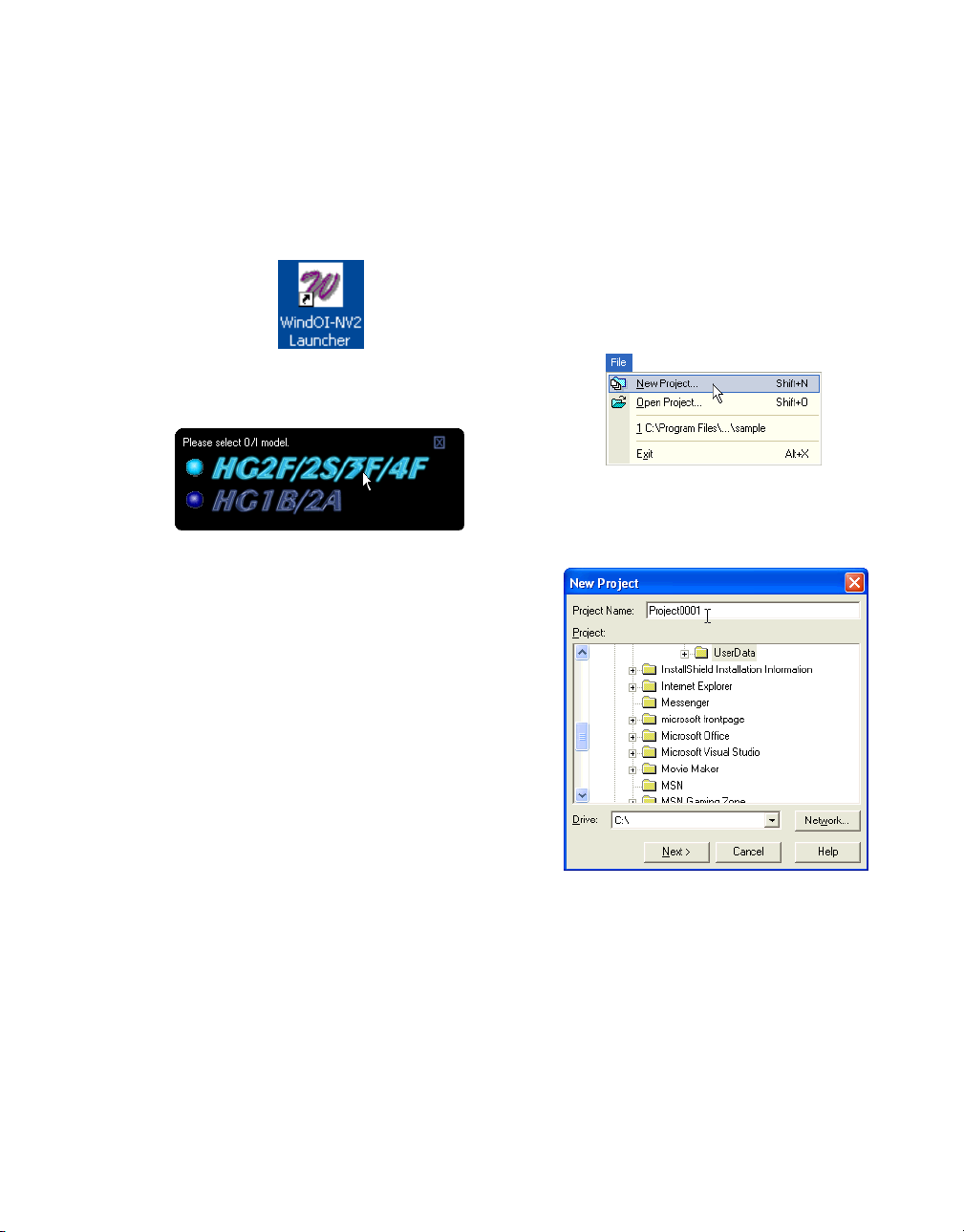
Double-click the [WindO/I-NV2 Launcher] icon
on your desktop. WindO/I-NV2 will open.
Select the mode that you will use to create the
data. In this case, select [HG2F/2S/3F/4F] in
the window.
A confirmation message will appear. Click
[Yes]. WindO/I-NV2 will open.
1.2 Creating Data
1.2.1 Creating a Project
Tutorial: You will create a new project for the
HG2F. This project name is "Project0001" and
an IDEC FC3A PLC will be used.
Click [New Project] on the toolbar (or select
[File] [New Project] from the menu).
Enter a project name in the [Project Name] edit
box. In this case, enter "Project0001".
Click [Next].
A confirmation message will appear. Click
[Yes].
The Select O/I Type dialog box will appear.
1-1
Page 10
How to Use WindO/I-NV2
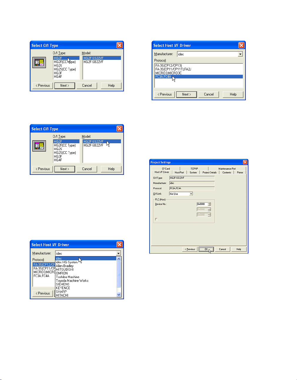
Select an [O/I Type]. In this case, select
"HG2F".
Select a [Model]. In this case, select "HG2F-
SS22VF".
Select the protocol in [Protocol] list box. In this
case, select "FC3A, FC4A".
Click [Next].
The Project Settings dialog box will appear.
Click [Next].
The Select Host I/F Driver dialog box will
appear.
Select a [Manufacturer]. In this case, select
"idec".
1-2
Depending upon the situation, the settings can
be changed.
Click [OK].
Page 11
1.2.2 Creating a Base Screen
Tutorial: You will create a base screen. The
screen number will be 2, it will have “Sample
Screen” for a title, and have a background color
of Dark Cyan (025).
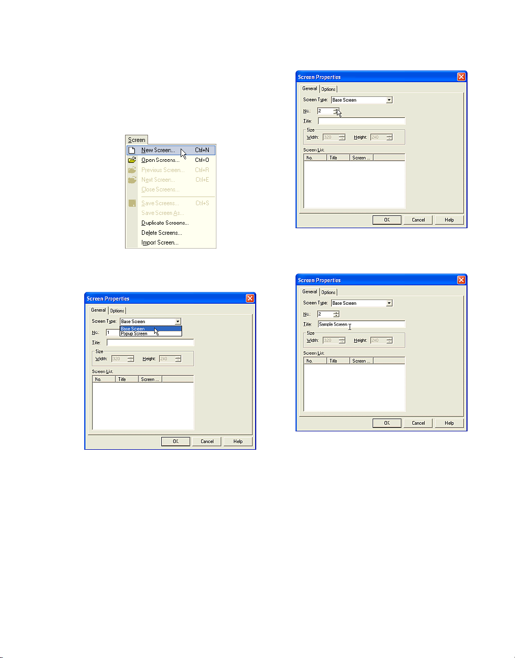
Click [New Screen] on the toolbar (or select
[Screen] [New Screen] from the menu).
Creating Data
Enter a screen [No.]. In this case, enter "2".
Select a [Screen Type]. In this case, select
"Base Screen".
Enter a [Title]. In this case, enter "Sample
Screen".
Click [Options] tab.
1-3
Page 12
How to Use WindO/I-NV2
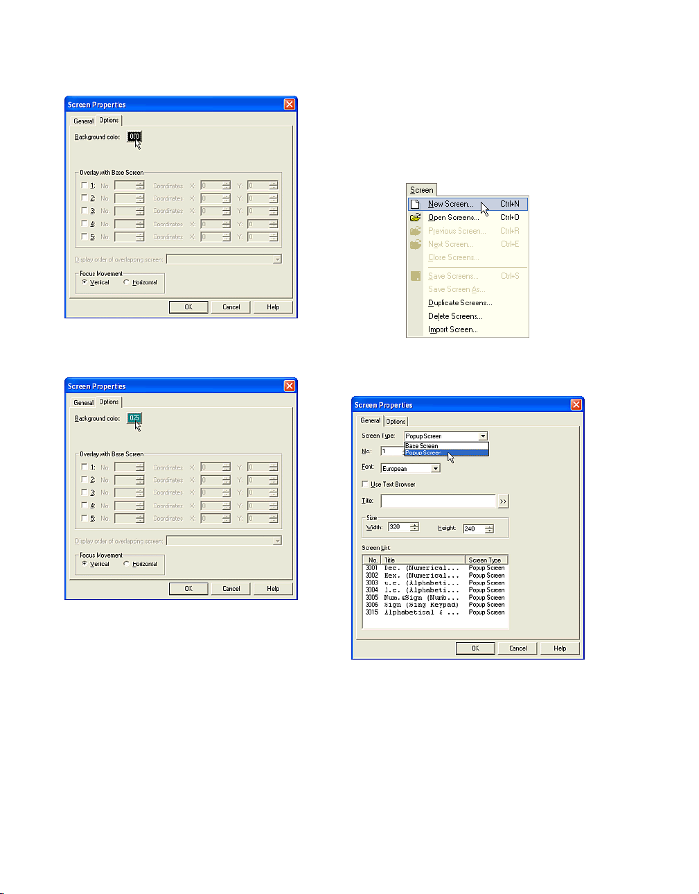
Click [Background color]. The Color Palette will
appear. In this case, click on "025".
1.2.3 Creating a Popup Screen
Tutorial: You will crate a Popup Screen. The
screen number will be 1000, the size will be 200
x 100, and the background color will be Black
(000).
Click [New Screen] on the toolbar (or select
[Screen] [New Screen] from the menu).
Click [OK].
The created screen will appear and the background color will change to the selected color.
1-4
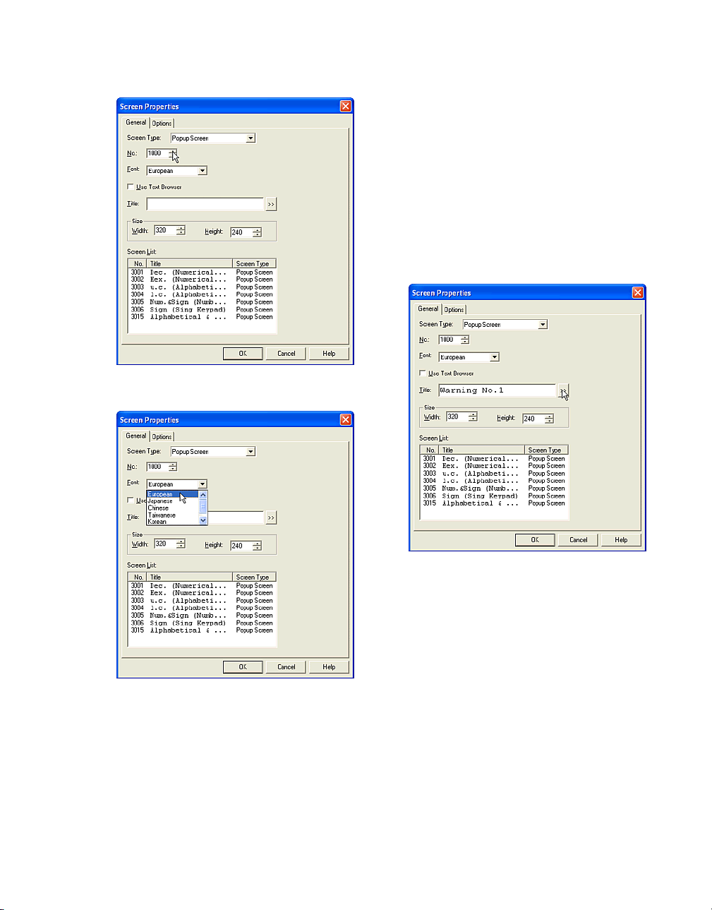
Select a [Screen Type]. In this case, select
"Popup Screen".
Page 13
Creating Data
Enter a [No.]. In this case, enter "1000".
If you want to use already registered text from
the Text Browser as the title of the Popup
Screen, check this box. (The Text ID settings
will appear. Enter the ID number of the text you
want or click the […] button to access the Text
Browser. Select the desired text and click
[Select]. The Text Browser will close and the
selected number from the Text Browser will
appear in the Text ID box on the General tab.
The text of the Text ID number you selected will
appear in the Title box.)
Select a [Font]. In this case, enter "European".
This setting is available for the title of the
Popup Screen when the Use Text Browse isn’t
checked.
Enter a [Title]. In this case, enter "Warning
No.1".
If you want to use a special character, click the
">>" button. (The Unicode Input dialog box will
appear. You can then input characters from languages other than the OS language. See the
Instruction Manual for details.)
1-5
Page 14
How to Use WindO/I-NV2
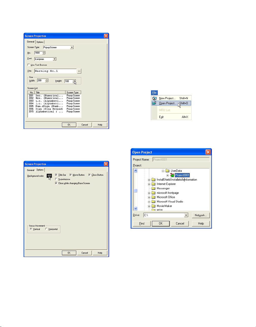
Enter a [Width] and a [Height]. In this case,
enter "200" and “100”.
Click [Options] tab.
1.3 Editing Data
1.3.1 Editing a Project
Tutorial: You will open an existing project
named "Project0001".
Note: If you haven’t already created a project,
you’ll need to do so before beginning this tutorial.
Click [Open Project] on the toolbar (or select
[File] [Open Project] from the menu).
Click [Background color]. The Color Palette will
appear. In this case, click "000".
Click [OK].
The created screen will appear and the background color will change to the selected color.
1-6
Select the data file in the [Project] list box. The
selected project name will appear in the
[Project Name] text box. In this case, select
"Project0001".
Click [OK]. The selected project will open.
Page 15
1.3.2 Editing Screens
Tutorial: You will open and edit Base Screen 1,
2 and 3 and Popup Screen 1000.
Note: If you haven’t already created screen
data, you’ll need to do so before you continue
with this tutorial.
Editing Data
Select a number in the [Screen List]. To select
more than one screen, use the Shift key and
Ctrl key. In this case, select "1", "2", "3" and
"1000". (Click "1" and then click "3" while holding down the Shift key. Then, click "1000" while
holding down the Ctrl key.)
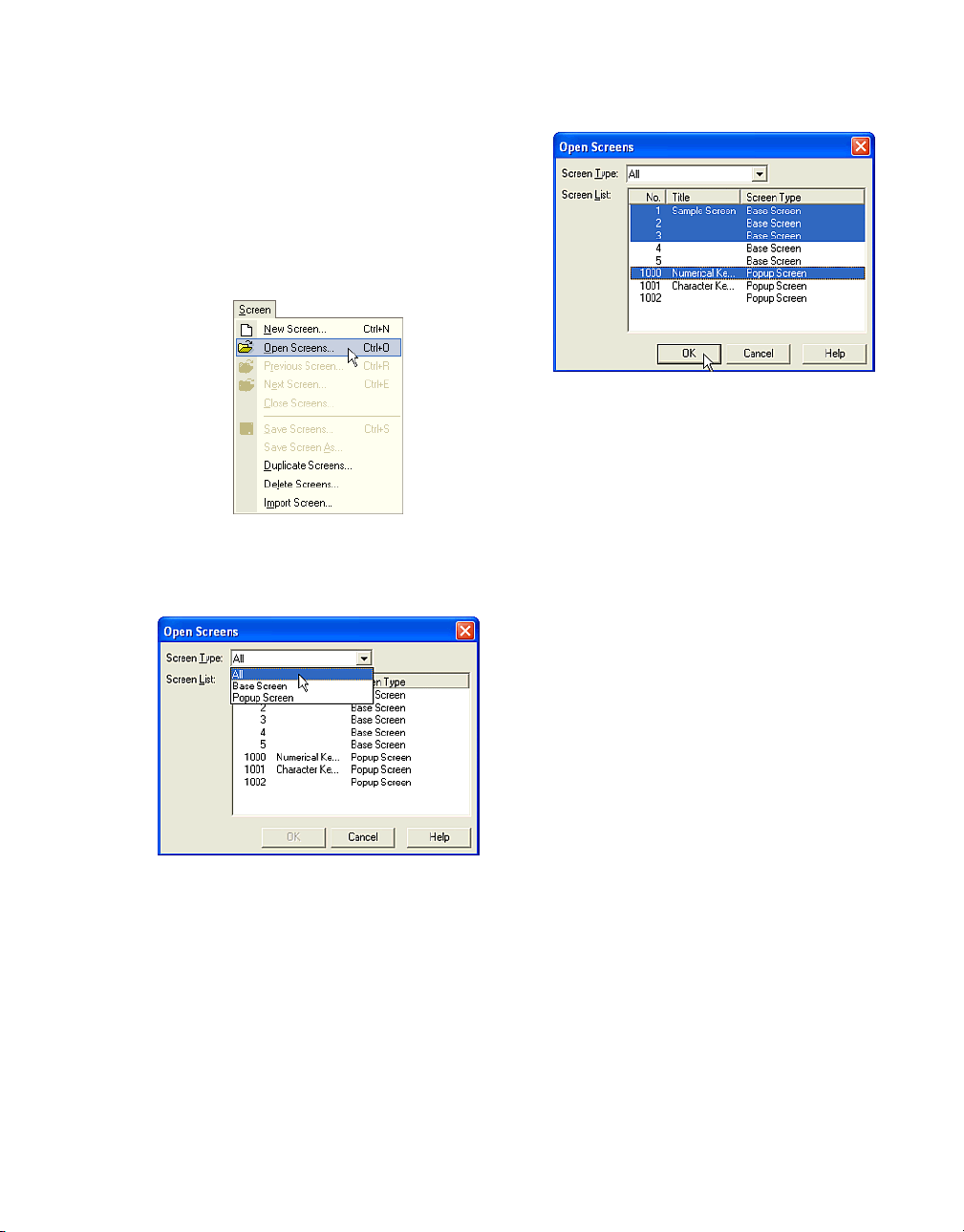
Click [Open Screens] on the toolbar (or select
[Screen] [Open Screens] from the menu).
Select a [Screen Type]. The existing screens of
the selected type will appear in the [Screen
List]. (If you select "All" in "Screen Type", all
existing screens will appear in this list. If there
isn’t a screen or all screens are already
opened, the list box is blank.) In this case,
select "All".
Click [OK]. The selected screens will open.
1-7
Page 16
How to Use WindO/I-NV2
1.3.3 Duplicating Screens
Tutorial: You will duplicate Base Screens 1, 2,
3, 4 and 10 twice. The start number of the duplicated screens will be 100.
Note: If you haven’t already created screen
data, you’ll need to do so before beginning the
next step.
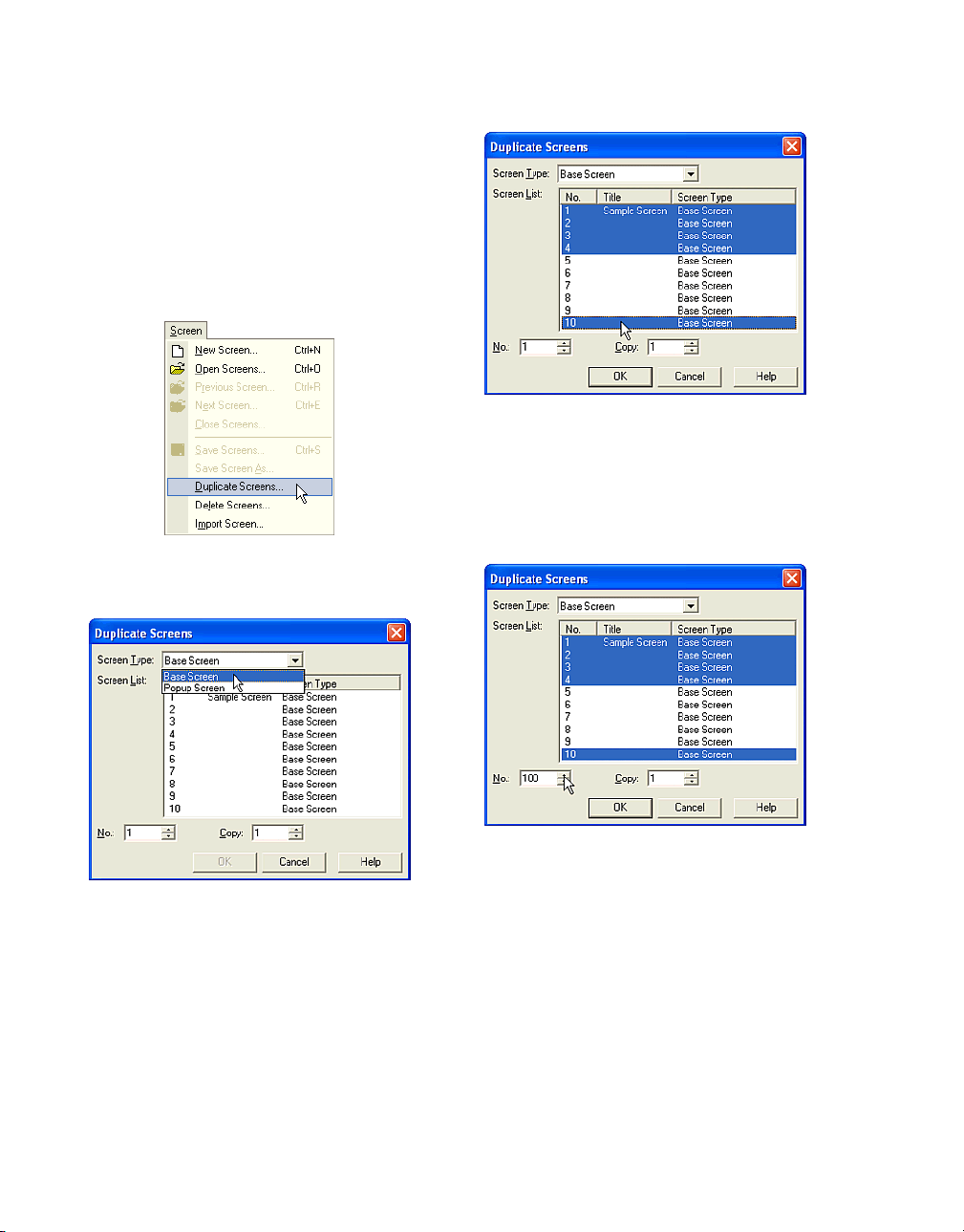
Select [Screen] [Duplicate Screens] from the
menu.
Select a number in the [Screen List]. When you
select more than one screen, use the Shift key
and Ctrl key. In this case, select "1", "2", "3", "4"
and "10". (Click "1" and then click "4" while
holding down the Shift key. Then, click "100"
while holding down the Ctrl key.)
Select a [Screen Type]. The existing screens of
the selected type will appear in the [Screen
List]. In this case, select "Base Screen".
1-8
Enter a start [No.]. This refers to the beginning
number of the duplicated screens. In this case,
enter "100".
Page 17
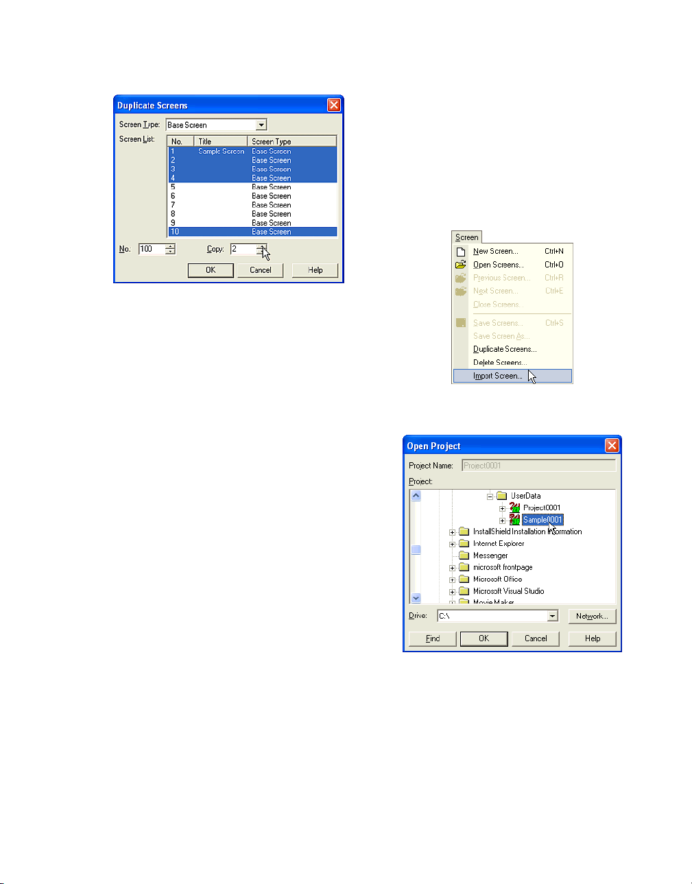
Enter a number in the [Copy] box. This refers to
the number of copies of each screen you want
to create. In this case, enter "2".
Click [OK].
Editing Data
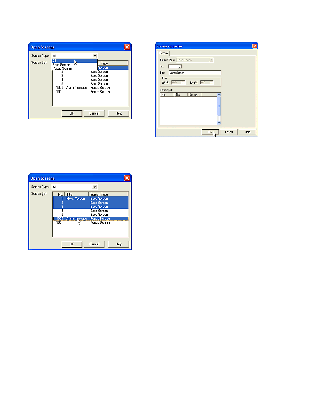
1.3.4 Importing Screens
You can import screens from a project that is a
different O/I or a different Host I/F.
Tutorial: You have created projects
"Project0001" and "Sample0001". You will edit
"Project0001" data. Base Screen 1, 2 and 3,
and Popup Screen 1000, will be imported from
"Sample0001".
When you open the Open Screens dialog box
you will see that Base Screens 100 to 109 were
created in the Screen List. When screens are
duplicated, they will be numbered sequentially
starting with the number listed in the Screen
[No.] box (in this case 100). Therefore, the copy
of Screen “1” will be numbered “100”, the copy
of Screen” 2” will be numbered “101” and so on
(the copy of Screen “10” will be numbered
“104”).
Since 2 copies of each screen was selected,
the second set of screens will be numbered
sequentially starting with the last assigned
number (the second copy of Screen “1” will be
numbered “105”, the second copy of Screen “2”
will be numbered “106”, and so on).
Select [Screen] [Import Screens] from the
menu.
Select a [Project]. The selected project name
will appear in the [Project Name] text box. In
this case, select "Sample0001".
Click [OK].
1-9
Page 18
How to Use WindO/I-NV2
Select a [Screen Type]. The existing screens
for the selected type will appear in the [Screen
List] box. (If you select "All" in [Screen Type], all
of the existing screens will appear in this list. If
there isn’t an existing screen, the list box is
blank.) In this case, select "All".
The original screen type is shown in [Screen
Type] dropdown list. As needed enter a screen
number in the [No.] box and a title in the [Title]
box.
The defaults are the same number and the
same title as the original screen.
Select a number in the [Screen List]. To select
more than one screen, use the Shift key and
Ctrl key. In this case, select "1", "2", "3" and
"1000". (Click "1" and then click "3" while holding down the Shift key. Then, click "1000" while
holding down the Ctrl key.)
Click [OK].
In this case, you will not change it.
Click [OK].
When you import multiple screens, this dialog
box will appear once for each screen being
imported.
1-10
Page 19
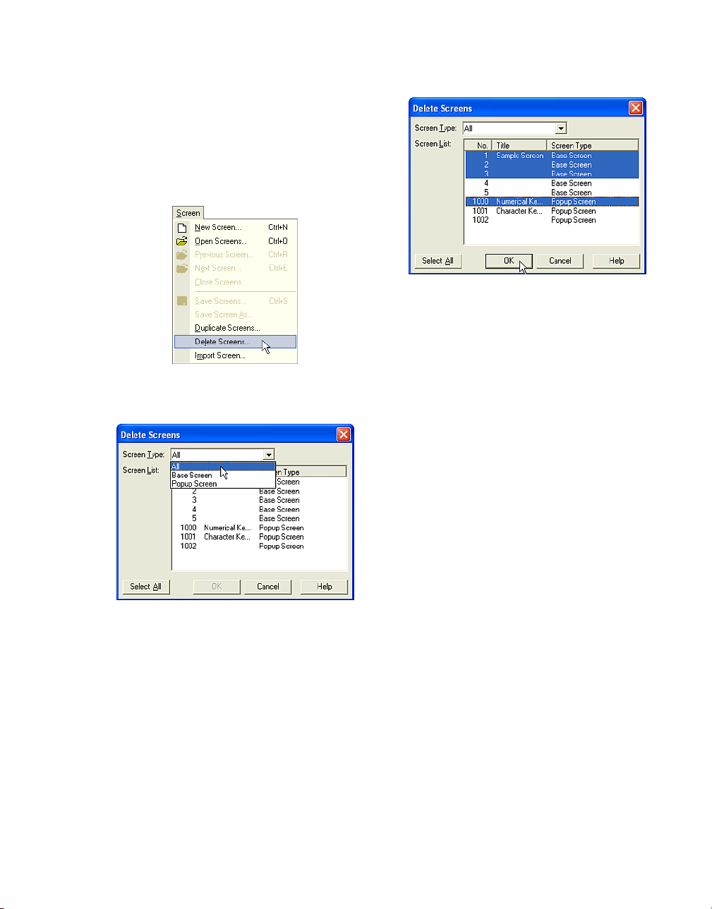
1.3.5 Deleting Screens
To delete unnecessary screens please do the
following.
Tutorial: You have created 10 Base Screens.
Base Screen 1, 2 and 3 and Popup Screen
1000 will be deleted.
Select [Screen] [Delete Screens] from the
menu.
Editing Data
Select a number in the [Screen List]. To select
more than one screen, use the Shift key and
Ctrl key. In this case, select "1", "2", "3" and
"1000". (Click "1" and then click "3" while holding down the Shift key. Then, click "1000" while
holding down the Ctrl key.)
Click [OK] and a confirmation message will
appear.
Select the type in [Screen Type] dropdown list.
The existing screens of the selected type will
appear in the [Screen List]. (If you select "All" in
[Screen Type], all of the existing screens will
appear in this list. If there isn’t an existing
screen, the list box is blank.) In this case, select
"All".
Click [Yes To All] on the message box if you
don’t need to confirm each screen. Base
Screen 1, 2 and 3, and Popup Screen 1000 will
be deleted from the [Screen List] when you
open the [Open Screens] dialog box.
1-11
Page 20
How to Use WindO/I-NV2
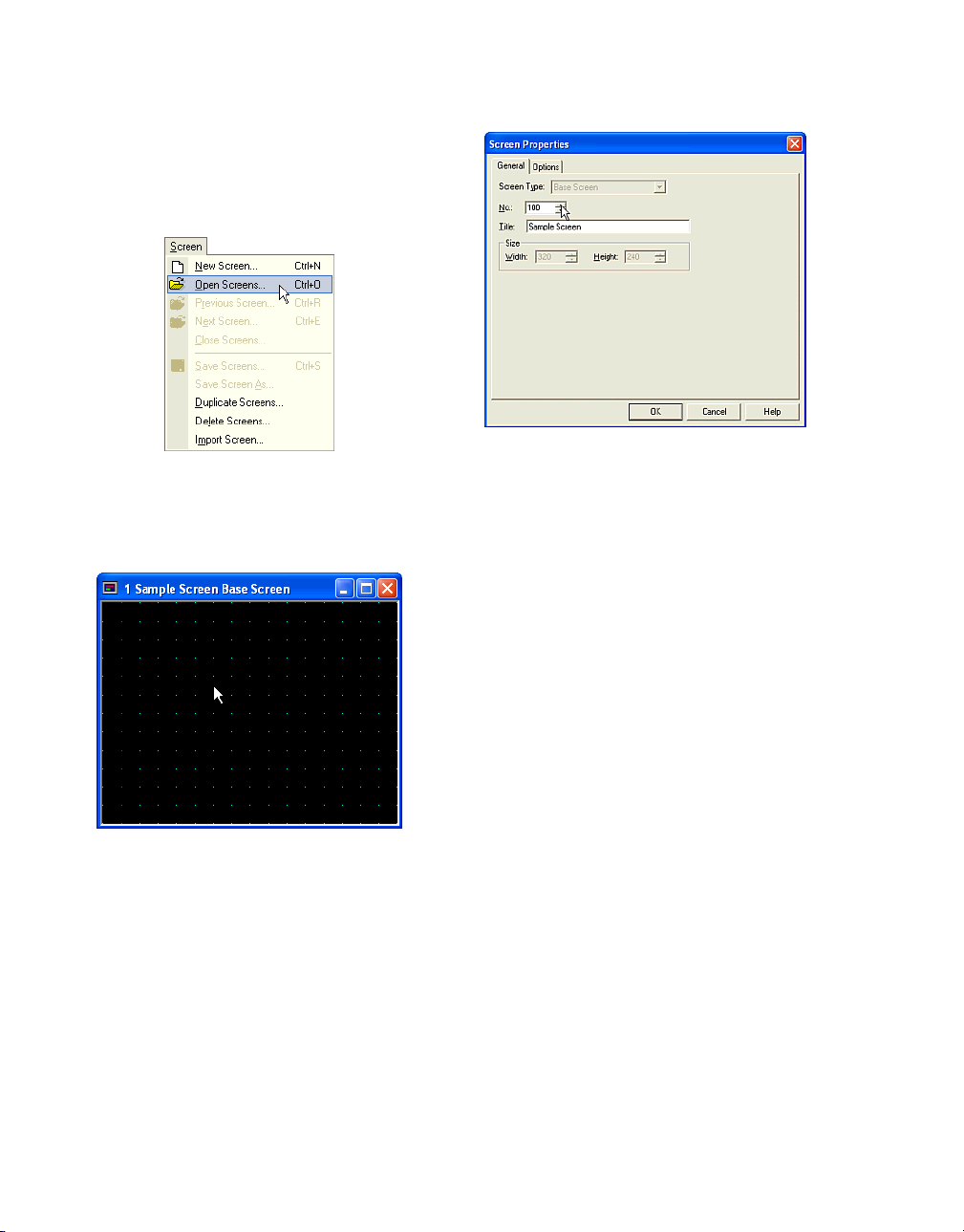
1.3.6 Changing Screen Number
Tutorial: You have created "Base Screen 1".
You will now change the screens number from
"1" to "100".
Select [Screen] [Open Screens] from the menu.
Open "Base Screen 1" (refer to “Editing
Screens” on page 1-7).
Double-click on the screen (or select [Edit]
[Properties] from the menu).
Enter a new number in the [No] box. In this
case, enter "100".
Click [OK].
The number on the title bar of the screen
changes from "1" to "100".
1-12
Page 21
Editing Data
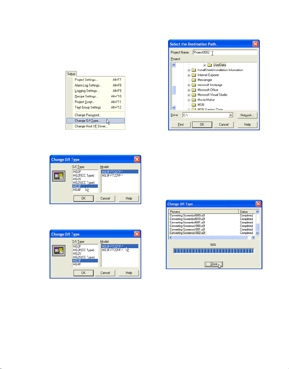
1.3.7 Changing O/I Type
Tutorial: You will edit "Project0001" data. You
will change the O/I type from "HG2F-SS22VF"
to "HG3F-FT22TF-*" as in "Project0002".
Select [Setup] [Change O/I Type] from the
menu.
Enter a [Project Name] and select a location if
necessary.
In this case, enter "Project0002" and leave the
location as is and a confirmation message will
appear.
Click [Yes].
The change O/I Type dialog box will appear.
Select an [O/I Type]. In this case, select
"HG3F".
Select a [Model]. In this case, select "HG3F-
FT22TF-*".
Click [OK] and a confirmation message will
appear.
Click [OK] again.
You will see the progression of the data conversion in this dialog box. Click [Close] after the
progress bar has reached 100%.
1-13
Page 22
How to Use WindO/I-NV2
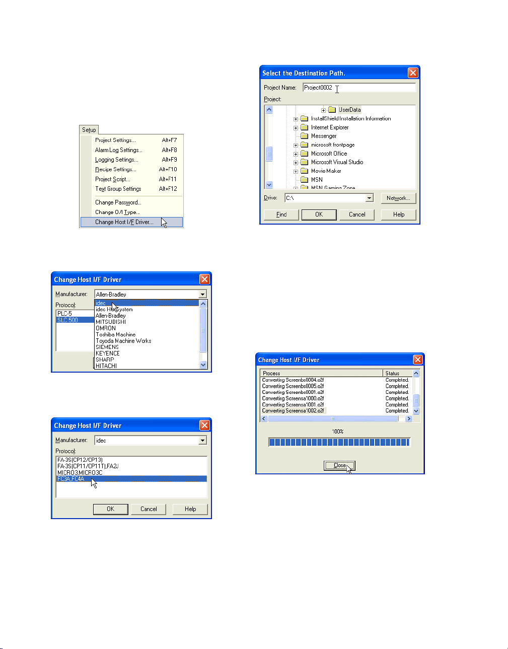
1.3.8 Changing Host I/F Driver
Tutorial: You will edit "Project0001" data. You
will change the Host I/F of this project data from
"Allen-Bradley: SLC500" to "idec: FC3A, FC4A"
as in "Project0002".
Select [Setup] [Change Host I/F Driver] from
the menu.
Enter a [Project Name] and select a location if
necessary. In this case, enter "Project0002"
and leave the location as is.
Click [OK] and a confirmation message will
appear.
Click [Yes].
The Change Host I/F Driver dialog box will
appear.
Select a [Manufacturer]. In this case, select
"idec".
Select a [Protocol]. In this case, select "FC3A,
FC4A".
Click [OK] and a confirmation message will
appear.
Click [OK] again.
1-14
You will see the progression of the data conversion in this dialog box. Click [Close] on the dialog box after the progress bar has reached
100%.
The previous host device will be converted to
the corresponding device of the new Host I/F
driver automatically. If the previous project used
a special device that the new Host I/F driver
doesn’t support, the device will be blank.
Page 23
1.4 Saving Data
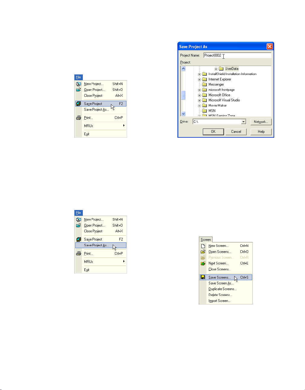
1.4.1 Saving a Project
Tutorial: You will save the edited project.
Saving Data
Click [Save Project] on the toolbar (or select
[File] [Save Project] from the menu).
1.4.2 Saving a Project With a New Name
Tutorial: You will resave "Project0001" as
"Project0002".
Select [File] [Save Project As] from the menu.
Enter a [Project Name] and select a location if
necessary. In this case, enter "Project0002"
and leave the location as is. A confirmation
message will appear.
Click [Yes].
1.4.3 Saving Multiple Screens
Tutorial: You are editing several screens.
You will save Base Screen 1, 2 and 3 and
Popup Screen 1000 all together.
Click [Save Screens] on the toolbar (or select
[Screen] [Save Screens] from the menu).
1-15
Page 24
How to Use WindO/I-NV2
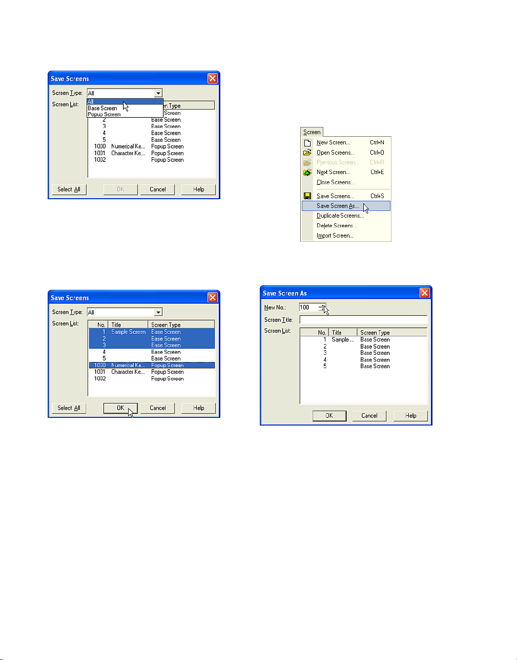
Select the type in [Screen Type] list.
The open screens of the selected type will
appear in the [Screen List]. (If you select "All" in
"Screen Type", all of the open screens will
appear in this list. If there isn’t an open screen,
the list box is blank.) In this case, select "All".
1.4.4 Saving a Screen With a New Number
Tutorial: You are editing "Base Screen 1". You
will save "Base Screen 1" as "100".
Select [Screen] [Save Screen As] from the
menu.
Select a number in the [Screen List]. To select
more than one screen, use the Shift key and
Ctrl key. In this case, select "1", "2", "3" and
"1000". (Click "1" and then click "3" while holding down the Shift key. Then, click "1000" while
holding down the Ctrl key.)
Click [OK].
1-16
Enter a new number in the [New No.] box. In
this case, enter "100".
Click [OK].
Base Screen 1 will be close without saving and
Base Screen 100 will appear.
Page 25
1.5 Setting Conditions
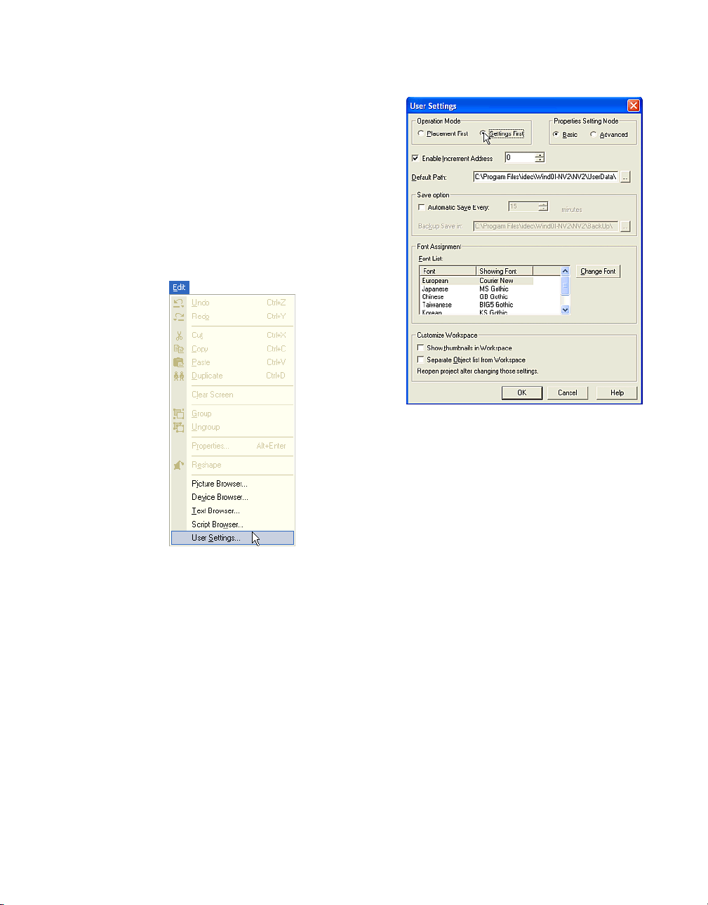
1.5.1 Setting an Operation
Tutorial: The properties dialog box will open
automatically after you select an object.
Note: If you open a properties dialog box after
placing an object on the screen you automatically select an operation. However, if you place
the objects first and then edit them, you won’t
change the default settings.
Setting Conditions
Select an [Operation Mode]. In this case, select
"Settings First".
Select [Edit] [User Settings] from the menu.
Click [OK]. When you select an object on the
toolbar and place it on the screen, the properties dialog box will open automatically.
1-17
Page 26
How to Use WindO/I-NV2
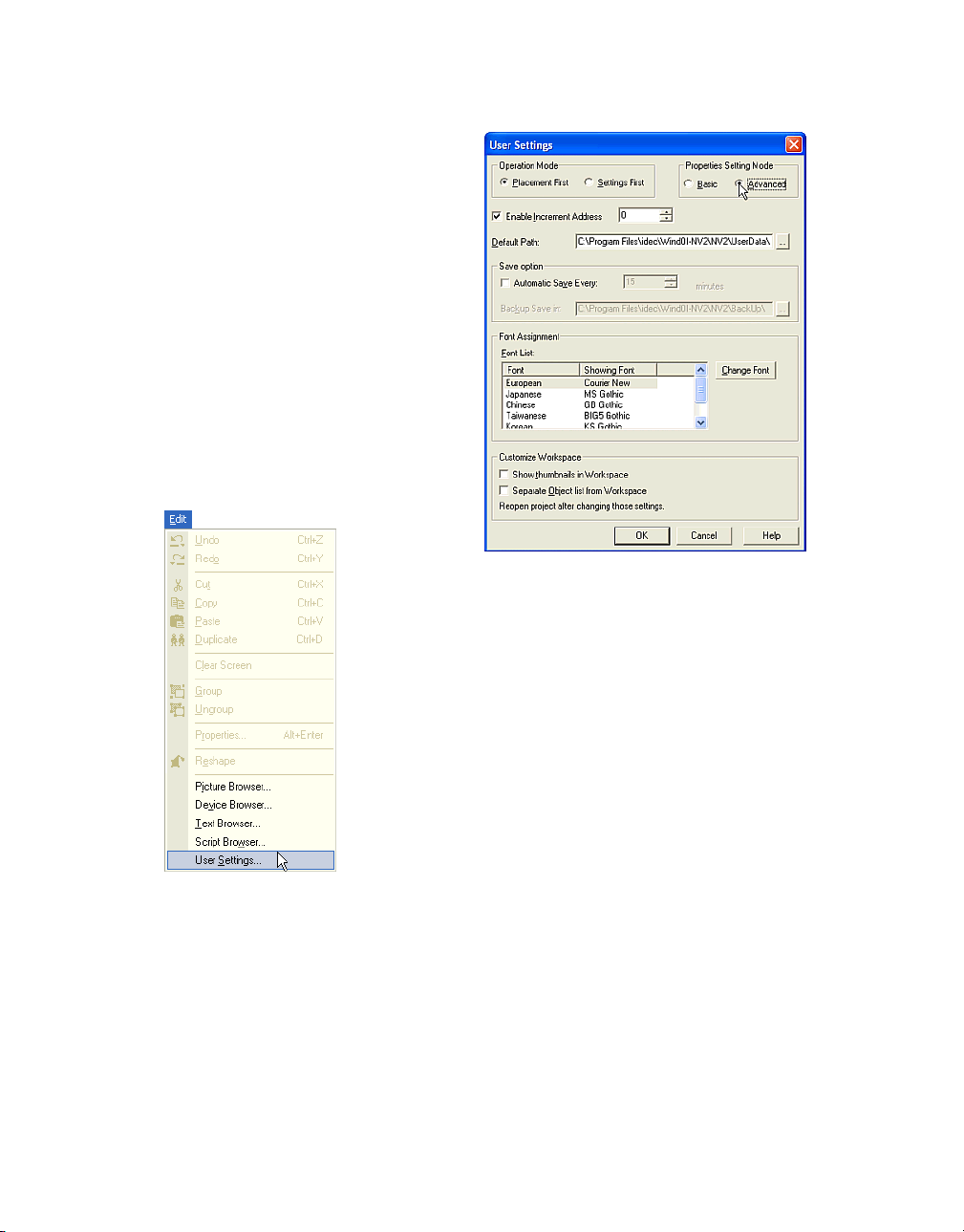
1.5.2 Selecting a Mode
Tutorial: The properties dialog box will automatically open with all advanced settings.
Note: If you open a properties dialog box with
all advanced settings after placing an object
you automatically select a mode. If you close
the dialog box after changing the mode, the
new mode is saved. This setting is only available when you place an object on the screen. If
you edit the object again, the dialog box is
opened with the same settings as when it was
closed. If you change the mode from
"Advanced" to "Basic" after setting the
advanced settings, the settings will return to the
default.
Select an item in [Properties Setting Mode] box.
In this case, select "Advanced”.
Select [Edit] [User Settings] from the menu.
1-18
Click [OK]. When you select an object on the
toolbar, place it on the screen and double-click
on it, the properties box will open automatically
with all advanced settings.
Page 27
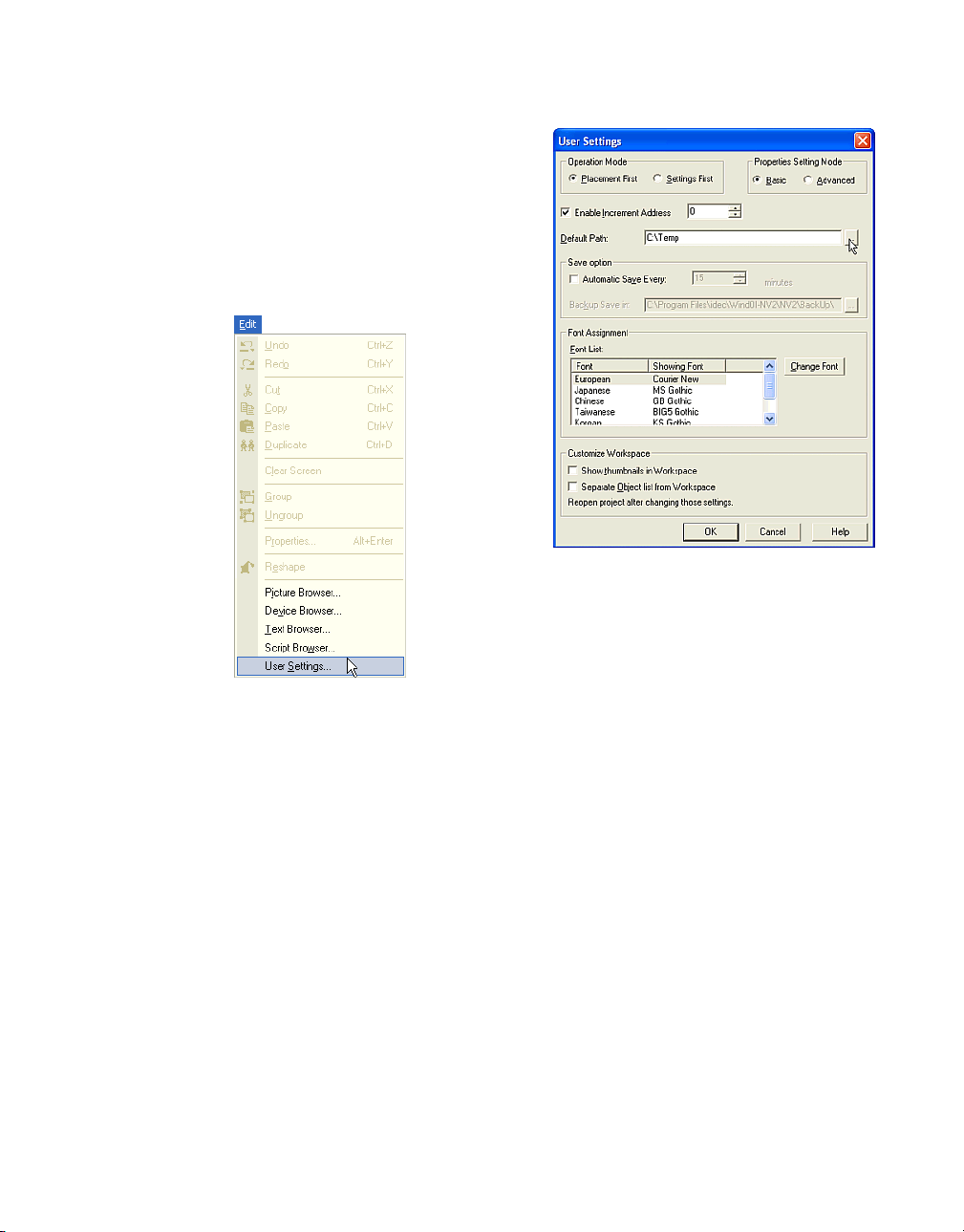
1.5.3 Setting a Default Path
Tutorial: You will change the default path from
"C:\Program Files\idec\WindOI-NV2\NV2\UserData" to "C:\Temp".
Note: This setting is available when you select
"New Project", "Change O/I" or "Change Host
I/F Driver" from the menu. The selected default
path will be shown in these dialog boxes.
Set a [Default Path]. In this case, enter or select
"C:\Temp".
Setting Conditions
Select [Edit] [User Settings] from the menu.
Click [OK]. You will see this setting when you
create a new project or change O/I type etc.
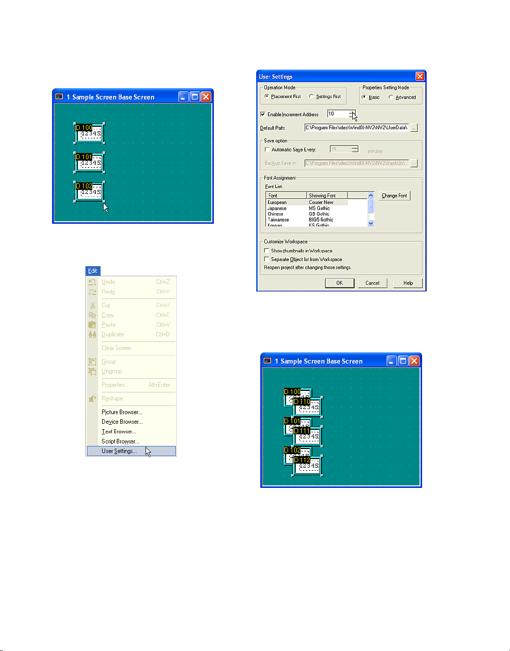
1.5.4 Automatically Adjusting an Address
Tutorial: You have three Numerical Displays
and you will create three new Numerical Displays by coping and pasting.
Note: When you copy and paste an object, the
setting address will increase or decrease automatically. For example, if you set a minus value,
the address will decrease.
The existing data is:
Part Name: Display Device
NumericalDisplay1: D 100
(“D” refers to Data Register)
NumericalDisplay2: D 101
NumericalDisplay3: D 102
The new data will be:
NumericalDisplay4: D 110
1-19
Page 28
How to Use WindO/I-NV2
NumericalDisplay5: D 111
NumericalDisplay6: D 112
There are three Numerical Displays on the
screen.
Check [Enable Increment Address] box and
enter a value. In this case, enter "
10".
Select [Edit] [User Settings] from the menu.
1-20
Click [OK].
Select and copy the three Numerical Displays
and paste them on the screen. The addresses
of the pasted objects will increase.
Page 29
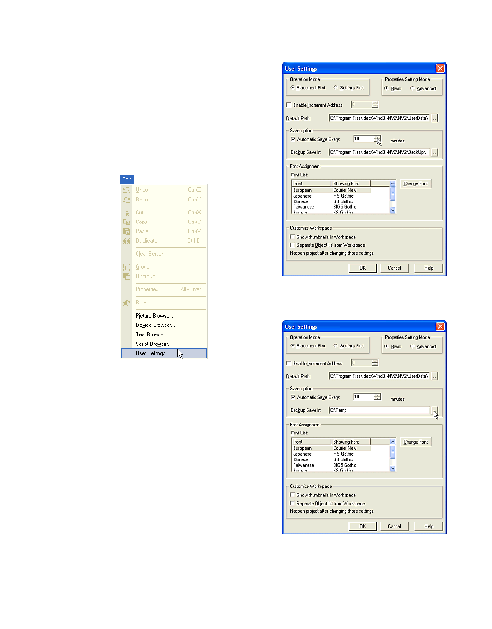
1.5.5 Automatically Saving Data
Tutorial: You will set the program to make a
backup copy every 10 minutes in "C\Program
Files\idec\WindOI-NV2\NV2\BackUp".
Note: The software automatically makes a
backup copy at the interval you enter, in minutes, and to the location you select in [Backup
Save] box.
Check the [Automatic Save Every] box and
enter an interval in the [minutes] box. In this
case, enter "10".
Select [Edit] [User Settings] from the menu.
Set a path in the [Backup Save in] box. In this
case, enter or select "C:\Temp ".
Click [OK].
1-21
Page 30
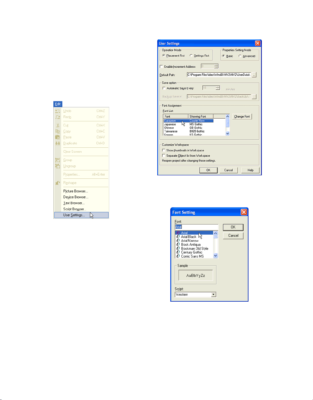
1.5.6 Changing the Displayed Font
Tutorial: You will change the displayed font on a
text box or some controls in the setting dialog
box.
Note: The selected font in this setting is available on the PC only. These fonts aren’t displayed on the HG series.
Select the font from [Font List] in [Font Assignment] box.The default display font is shown. In
this case, select "European".
Select [Edit] [User Settings] from the menu.
1-22
Click [Change Font]. The Font Setting dialog
box will appear. Select a font from the [Font]
list. In this case, select "Arial". A sample of the
selected font will be shown in the [Sample] box.
Page 31
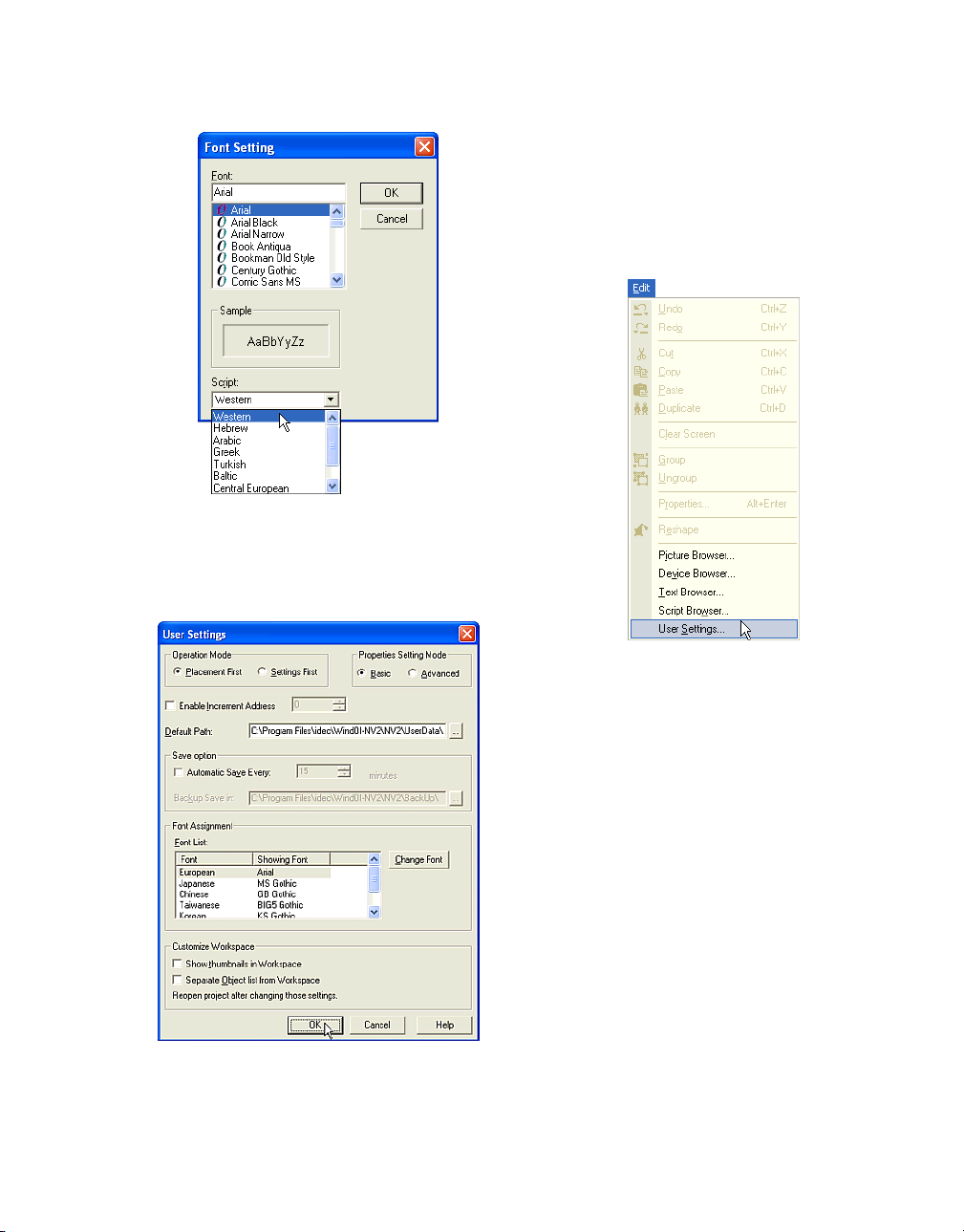
Select a script from the [Script] list. In this case,
select "Western".
Click [OK].
1.5.7 Displaying Screens as Thumbnails
Tutorial: You will display the screens as thumbnails.
Note: You need to reopen the project to enable
this setting.
Select [Edit] [User Settings] from the menu.
The selected font will be displayed in the [Font
List].
1-23
Page 32

Click the [Show thumbnails in Workspace] box
so the Screen tab appears in the Workspace
when you reopen the project.
1.5.8 Displaying Object List
Tutorial: You will display the Object list separately from the Workspace .
Note: You need to reopen the project to enable
this setting.
Select [Edit] [User Settings] from the menu.
When you open a project, the Screen tab
appears in the Worksapace.
Click the Screen tab, you will see the screens
as thumbnails.
1-24
Page 33

Check the [Separate Object list from Workspace] box so the Object list appears on the left
side of the window when you reopen the
project.
Logging Data
1.6 Logging Data
1.6.1 Setting Alarm Logging Data
Tutorial: You will monitor three devices and the
conditions are as follows.
Note: By setting this function the HG monitors
devices and keeps the date and time when the
state of each bit changes. When the state of the
bit changes, it is regarded as an alarm. If you
use part objects for this data, you can check
them on the HG screen.
- Data Register (D1000, D1001 and D1002)
will be monitored.
- The HG will monitor these devices every five
seconds.
- When the alarm log storage area becomes
full, the HG will stop storing new data until it
is initialized.
- The number of generated alarms will be
stored in the HG Data Register (LDR1000).
You can check this function if you set Numerical Display etc. on the screen.
- The alarm log storage area is initialized when
the selected device turns from 0 to 1.The trigger device is HG Internal Relay (LM1000).
You can check this function if you set Bit Button etc. on the screen.
- When an alarm occurs, the screen will appear
to check the state of the device. The screen
number is "2000" and the coordinate is "(100,
100)".
- When an alarm occurs, the O/I beeps.
- When an alarm occurs, the date and time for
"D1000" will be stored, but other data won’t
be kept.
- It will be an alarm for some devices (from
"D1000-0" to "D1000-7", D10001 and D1002)
when the bit turns from 0 to 1, but it is also an
alarm for other devices (from "D1000-8" to
D1000-15") when the bit turns from 1 to 0.
- You won’t monitor the bits from D1001-8 to
D1001-15. If you don’t monitor all the bits, an
alarm won’t occur even when an unmonitored bit turns on. In addition, other settings
1-25
Page 34

won’t work - if you select data to be stored
(the date and time), open the screen and
show text or the screen on the part object
because the bits are not being monitored.
Select [Setup] [Alarm Log Settings] from the
menu.
Select a [Storage Method]. In this case, select
"Fixed" because you won’t store new data
when the alarm log storage area becomes full.
Enter the number of the device for monitoring in
the [No. of Blocks] box. In this case, enter "3"
because you will monitor three devices.
1-26
Enter a [Monitoring Period] value. In this case,
enter "50" because you will monitor every 5
seconds.
Page 35

Logging Data
Click [Monitor No. of Currently Active Alarms]
and set the device. In this case, enter
"LDR1000". The number of the generated
alarm is stored as "LDR1000".
If you check this function on the HG, please
create the part object to show a numerical
value. (E.g. Numerical Display).
Click [Erase Log Data] and set the device.
When the selected bit turns from 0 to 1, it is initialized. In this case, enter "LM1000".
If you check this function on the HG, please
create the part object to turn from 0 to 1. (E.g.
Bit Button).
Click [Call Popup Screen]. Then enter "2000" in
the [Popup Screen No.] box and "100" in the [X]
and [Y] boxes. When an alarm occurs, this
screen will appear.
Create Popup Screen 2000 after you set Alarm
Log Settings. For more information refer to
“Creating a Popup Screen” on page 1-4. When
an alarm occurs, Popup Screen 2000 will
appear at (100, 100).
Enter the [No. of stored log data for Alarm]
value. In this case, enter "624". The operator
interface stores the Alarm log data of the specified number in this setting in the backup area
after a power interruption.
1-27
Page 36

Click [Beep when Alarm occurs]. When an
alarm occurs, the O/I will start beeping. (Refer
to the Instruction Manual for details.)
Click [Channel] tab. Select a [Reference
Screen]. In this case, select "Not use". You
won’t use the part object for this function. For
more information see “Using Alarm Log Display
to Display Logging Data” on page 2-97.
Click [Auto]. The Auto Settings dialog box will
appear. All data is automatically set when you
set the settings for Channel 1-0 in this dialog
box. In this case, all items are set in order from
Channel 1-0 to 3-15.
Set a device in the [Source] box. In this case,
enter "D1000" because you will monitor
"D1000", "D1001" and "D1002".
1-28
Select a method in the [Store/No Store] box. In
this case, select "Store" because you want to
store the data for "D1000", but not for "D1001"
and "D1002". After this dialog box closes, you
can change this setting for "D1001" and
"D1002".
Page 37

Logging Data
Select a state in the [Enable/Disable] box. In
this case, select "Enable" because you will
monitor the selected devices (but you won’t
monitor bits from D1000-8 to D1000-15). After
closing this dialog box, you can change this setting for D1000-8 to D1000-15.
Select an alarm state in [NO/NC] box. In this
case, select "NO" because an alarm occurs
when the bit of "D1000" turns from 0 to 1. For
example, an alarm occurs when "D1000-0"
turns from 0 to 1. But an alarm also occurs
when the bit of "D1001" or "D1002" turns from 1
to 0. After this dialog box closes, you can
change this setting for "D1001" or "D1002".
Click [Text ID]. You won’t use the part object for
this function. For more information see “Displaying Multiple Messages with Alarm List Display” on page 2-84 or “Using Alarm Log Display
to Display Logging Data” on page 2-97.
Click [OK]. The settings of Channel 1-0 to 3-15
are automatically set in order.
In this case, click on “Store” in the [Store/Not
Store] column for channel numbers "2-*" and
"3-*". The settings change from "Store" to "Not
Store" since you want to keep D1000 data, but
not D1001 and D1002 data. You cannot select
this setting for every bit. If you change one bit it
changes them all in the block.
1-29
Page 38

1.6.2 Setting Trend Logging Data
Tutorial: You will log three devices and the conditions are as follows.
Note: The operator interface records the date
and time, and the device data, based on the
sampling period. If you use part objects for this
data, you can check them on the operator interface screen. When the trend log storage area
becomes full, new data will overwrite the oldest
data.
Click on NO in the [NO/NC] column for channel
numbers "D1000-8" to "D1000-15". The settings change from "NO" to "NC" since an alarm
will occur when the bit from "D1000-8" to
"D1000-15" turns form 1 to 0. You can select
this setting for every bit.
Click Enable in the [Enable/Disable] column for
channel numbers "D1001-8" to "D1001-15*".
The settings change from "Enable" to "Disable"
since you won’t be monitoring these bits. You
can select this setting for every bit.
Click [OK].
- Data Register (D2000, D2100 and D2200)
will be recorded.
- D2000 will be set to Device Log No.1, D2100
will be set to Device Log No.5 and D2200 will
be set to Device Log No.10.
- The D2000 data will be recorded every five
seconds and the number of logging data will
be stored to LDR 2000. You can check this
function if you set Numerical Display etc. on
the screen.
- The D2100 data will be recorded when the
operator interface Internal Relay (LM210)
turns from 0 to 1.
- The D2200 data will be recorded when the
value of the operator interface Internal Register (LDR220) changes.
- The logging data is initialized when the
selected device turns from 0 to 1. The trigger
device is HG Internal Relay (LM1000). You
can check this function if you set a Bit Button
etc. on the screen.
1-30
Page 39

Select [Setup] [Logging Settings] from the
menu.
Logging Data
Enter a [Device Log No.]. In this case, enter "1"
because you will use Device Log No.1.
Click [Edit]. The Individual Device Log Settings
dialog box will appear.
Select a state in [Enable/Disable] box. In this
case, select "Enable" because you use Device
Log No.1.
1-31
Page 40

Set a device in the [Source] box. In this case,
enter "D2000" because you will set "D2000" to
Device Log No.1.
Set the condition in [Sampling Method] box. In
this case, select "Fixed Period" and enter "5"
because you will record "D2000" data every 5
seconds.
Check the [Monitor No. of Currently Logging
Data] box and set a device. In this case, enter
"LDR2000" because you will set the logging
data to be stored in Device Logging No.1 to
“LDR2000”.
Click [OK]. You will see the settings in the Set
Logs list.
Set Device Log No.5 in the same way as
Device Log No.1.
1-32
Click [Edit]. The Individual Device Log Settings
dialog box will appear. Enter a [Device Log
No.]. In this case, enter "5" because you will
use Device Log No.5.
Page 41

Logging Data
Select a state in [Enable/Disable] box. In this
case, select "Enable" because you will use
Device Log No.5.
Set a device in the [Source] box. In this case,
enter "D2100" because you will set "D2100" to
Device Log No.5.
Set the condition in the [Sampling Method] box.
In this case, select "Event Bit" and enter
"LM210" because you will record "D2100" data
when "LM210" turns from 0 to 1.
Click [OK]. You will see the settings in the Set
Log list.
Set Device Log No.10 in the same way as
Device Log No.1.
Click [Edit]. The Individual Device Log Settings
dialog box will appear. Enter a [Device Log
No.]. In this case, enter "10" because you will
use Device Log No.10.
In this case, select "Event Word" and enter
"LDR220" because you will record "D2200"
data when the value of "LDR220" changes.
Click [OK]. You will see the settings in the Set
Log list.
Check [Log to backup area] box.
In this case, the operator interface keeps the
logging data in the backup area after a power
interruption. The maximum number of stored
data depends on the setting of the Alarm Log
Settings. If you want to change it, click the […]
button. The Alarm Log Settings dialog box will
appear and you can change the number.
Select a state in [Enable/Disable]. In this case,
select "Enable" because you will use Device
Log No.10.
Set a device in the [Source]. In this case, enter
"D2200" because you will set "D2200" to
Device Log No.10.
Set the condition in the [Sampling Method] box.
1-33
Page 42
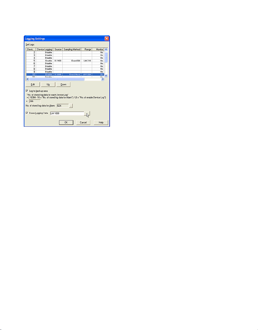
Check [Erase Logging Data] box and set the
device. When the selected bit turns from 0 to 1,
all logging data is initialized. In this case, enter
“LM1000”.
Click [OK]. You won’t use the part object for this
function. For more information see “Using a
Trend Chart to Display Logging Data” on
page 2-95.
1.7 Using Recipe Data
Tutorial: You set the initial data to 20 devices
(D0 to D4 and D10 to D24), copy the value of
10 devices (D50 to D59) to the CF Card and the
conditions are as follows.
Note: You can set the initial device data or get
the current device data by setting this function.
When a bit turns from 0 to 1, the data is written
to the device or copied from the device. If the
bit turns from 0 to 1 again, the data is overwritten. But if the bit turns from 0 to 1 again while
the data is being written, the data isn’t overwritten.
- You will set Block1 data to Internal Memory
and Block2 data to CF Card.
- You will set the initial data in Block1 to the
devices and copy device data to Block2.
- Data Register (D1000 and D1001) will be
monitored. D1000 is for Block1 and D1001 is
for Block2.
- The O/I will monitor these devices every five
seconds.
- When D1000-0 turns from 0 to 1, the data setting will be written to five devices (D0 to D4).
The data type will be Bin 16(+) and you will
enter the hexadecimal value in the setup dialog box.
- When D1000-1 turns from 0 to 1, the setup
data is written to fifteen devices (D10 to
D24). The data type will be Bin 16(+/-) and
you will enter the decimal value in this dialog
box by importing a file. You will create the initial data as a CSV file. The file name will be
"SampleRCP1.csv". The recipe data should
be separated with a comma and each value
is one line. The line will terminate with CR/LF.
SampleRCP1.csv is as follows.
1111,
2222,
….,
9999,
-1111,
1-34
Page 43

-2222,
…,
-9999,
- When D1001-15 turns from 0 to 1, the values
of ten devices (D50 to D59) will be copied to
the CF Card. The data type will be Bin32(+/-).
- You won’t use D1000-3 to D1000-15 and
D1001-0 to D1001-14.
Select [Setup] [Recipe Settings] from the menu.
Using Recipe Data
Select the location to store the recipe data in
the [Access To] box. In this case, select "Inter-
nal Memory". When you use "Internal Memory",
you can write the data to the device only. So,
"Write Only" is selected in the [Trigger Setting]
box.
Enter the number of the device that will be monitored in the [No. of Blocks] box. In this case,
enter "2" because you will monitor 2 devices.
The number will be set to [Ch.No.] from "1-0" to
"2-15" automatically. "1-0" is selected at first.
Click [Edit]. The Recipe Control Settings dialog
box will appear. "1" is displayed in [Block] and
"0" is displayed in [Channel]. You can set the
data for Ch.No.1-0 on Channel tab and for
Block1 on Block tab.
Click [Block] tab.
Set the device in the [Write Trigger] box. In this
case, enter "D1000" because you will monitor
"D1000" in Block1. The value of the [Monitoring
Period] box is set with the same value as the
alarm setting. In this case, "50" is shown
because you set "50" in the [Monitoring Period]
box in Alarm Log Settings dialog box.
1-35
Page 44

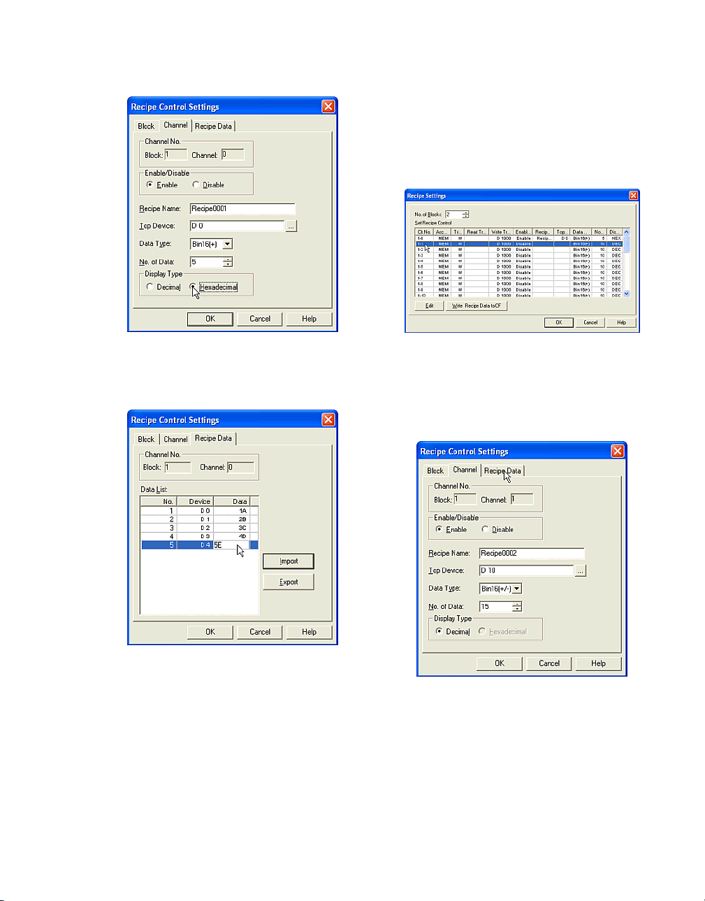
Click [Channel] tab. "1" is displayed in [Block]
and "0" is displayed in [Channel].
Select the state in [Enable/Disable] box. In this
case, select "Enable" because you will write the
data to the devices when "D1000-0" turns from
0 to 1. "D1000-0" is registered to Ch.No.1-0.
Enter a [Recipe Name]. The default setting is
"Recipe0001". This is a comment. In this case,
leave it is.
Select a [Data Type]. In this case, select
"Bin16(+)".
Enter a number in the [No. of Data] box. In this
case, enter "5" because you will write the data
to five devices.
Set the device in the [Top Device] box. In this
case, enter "D0" because you set the data to
D0. D0 is the start device.
1-36
Page 45
Using Recipe Data
enter the value as a hexadecimal because you
selected "Hexadecimal" in [Display Type] of
[Channel] tab.
Click [OK]. You will see that the settings of "1-0"
appear in [Set Recipe Control] list.
Select a [Display Type]. In this case, select
"Hexadecimal" because you will enter a hexadecimal value in Recipe Data tab.
Click [Recipe Data] tab. "1" is displayed in
[Block] and "0" is displayed in [Channel]. You
can set the initial data for Ch.No.1-0 on this tab.
You set "D0" to [Top Device] and "5" to [No. of
Data] in Channel tab. You will see that five
devices are shown in [Data List] list.
Select "1-1" in [Set Recipe Control] box.
Click [Edit]. The Recipe Control Settings dialog
box will appear. "1" is displayed in [Block] and
"1" is displayed in [Channel].
Set Ch.No.1-1 in the same way as Ch.No.1-0.
In this case, you don’t need to set the Block setting because you set one of the channels in
Block1.
In [Data List] double-click the value in the [Data]
column and enter a new value for each No. In
this case, set "1A" to [D0], "2B" to [D1], "3C" to
[D2], "4D" to [D3] and "5E" to [D4]. You can
Select "Enable" in [Enable/Disable] box. The
default setting is "Recipe0002" in [Recipe
Name] box and leave it as is.
1-37
Page 46
Select "D10" in [Top Device] box.
Select "Bin16(+/-)" in [Data Type] box.
Enter "15" in [No. of Data] box.
Select "Decimal" in [Display Type] box. You
cannot select "Hexadecimal" because you
selected "Bin16(+/-)" in [Data Type].
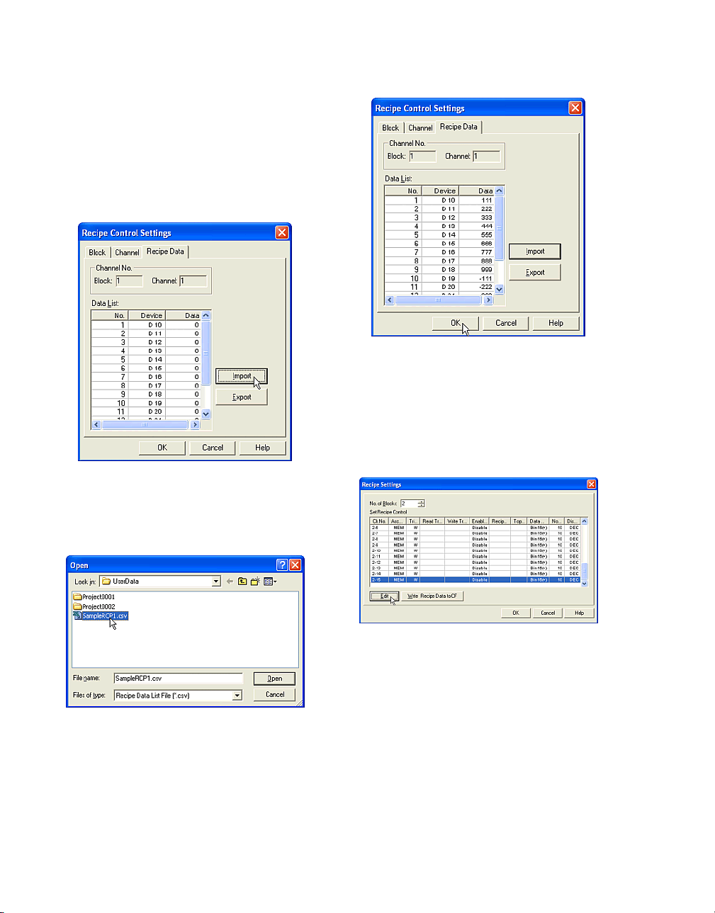
Click [Recipe Data] tab. "1" is displayed in
[Block] and "1" is displayed in [Channel].
The SampleRCP1.csv data file appears in the
[Data List] box. If the number of the recipe data
files exceeds the number of devices in [Data
List], only the number of devices will display the
data.
Click [OK].
Click [Import]. The Open dialog box will appear.
Select the data file in the list. In this case, select
"SampleRCP1.csv".
Click [Open]. After closing this dialog box, you
will see the values you just entered in the [Data
List] box.
1-38
Set Ch.No.2-15 in the same way as Ch.No.1-0.
Select "2-15" in [Set Recipe Control] box.
Click [Edit]. The Recipe Control Settings dialog
box will appear. "2" is displayed in [Block] and
"15" is displayed in [Channel].
Page 47
Using Recipe Data
Set Ch.No.2-15 in the same way as Ch.No.1-0.
In this case, you will need to set the Block setting because you set one of the channels in
Block2.
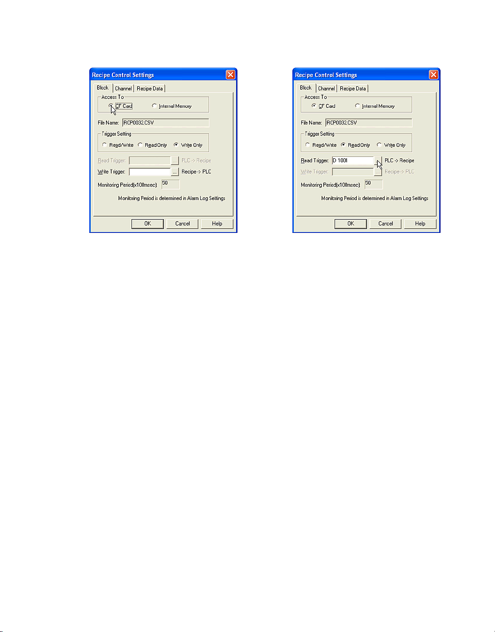
Click [Block] tab.
Select "CF Card" in the [Access To] box. When
you use the "CF Card" and copy the data from
the devices to the CF Card, the file name
appears in the [File Name] box. This names
each Ch.No. in order from RCP0001.CSV. You
will edit channels "2-15" and the name will be
"RCP0032.CSV".
Select a [Trigger Setting]. In this case, select
"Read Only" because you will copy the device
data to the CF Card and won’t set CF Card data
to the devices.
Set the device in the [Read Trigger] box. In this
case, enter "D1001" because you will monitor
"D1001" in Block2.
The value of the [Monitoring Period] box is set
as the same value as the alarm setting. In this
case, "50" is shown because you set "50" in the
[Monitoring Period] box in the Alarm Log Settings dialog box.
1-39
Page 48

Click [Channel] tab. "2" is displayed in [Block]
and "15" is displayed in [Channel].
Select "Enable" in [Enable/Disable] box.
The default setting is "Recipe0002" in [Recipe
Name] box and leave it as is.
Set "D50" in the [Top Device] box.
Select "Bin32(+/-)" in [Data Type] box.
1.8 Exiting WindO/I-NV2
Click [Close] at the upper left of the title bar (or
select [File] [Exit] from the menu). WindO/I-NV2
will close.
Enter "10" in the [No. of Data] box.
Click [OK].
1-40
Page 49

2.1 Drawing
2.1.1 Drawing a Line
The default settings will be the same as the previously drawn object.
Tutorial: You will draw a line on Base Screen 1.
After drawing, you will change the properties of
the line so that the width will be 2 dots, the color
will be red, the starting point will be (20, 20) and
the ending point at (200, 200).
Click the [Line] button on the toolbar (or select
[Draw] [Drawing] [Line] from the menu).
2. How to Use Objects
Click the point on the screen where you want
the line to start and drag the pointer to where
you want the line to end.
2.1.2 Changing Line Properties
In order to change the properties of this object
after drawing, please select and double-click
the object. The properties dialog box will
appear.
The icon image will change to the mode for
drawing an object. Double-click the [Line] button on the toolbar. If you draw more than one
line with the same style you can continue to
draw lines without having to select the button
on the toolbar again.
Select a [Line Width]. In this case, select "2
dots".
Select a [Line Type]. In this case, select "Dot".
Click [Line Color]. The Color Palette will appear.
In this case, select the red "020".
2-1
Page 50

How to Use Objects
If you want this object to blink check the [Blink]
box. In this case, leave it off. (Refer to the
Instruction Manual for more information on the
blincking cycle.)
Enter the coordinates for [Point1] (the starting
point) and [Point2] (the ending point). In this
case, enter "(20, 20)" for the starting point and
"(200, 200)" for the end point.
Click [OK].
2.1.3 Drawing a Polyline
The default settings will be the same as the previously drawn object.
Tutorial: You will draw a polyline on Base
Screen 1. After drawing, you will change the
properties of the line so that the width will be 1
dot, it will be yellow and a dashed line.
Click on the screen at the point where you want
the object to start.
Click the [Polyline] button on the toolbar (or
select [Draw] [Drawing] [Polyline] from the
menu).
The icon image will change to the mode for
drawing an object.
2-2
Click at each point on the screen where you
want to create an apex.
Double-click when done. After drawing, the
scale pointer will appear to enclose the points
with a rectangle.
Page 51
Drawing
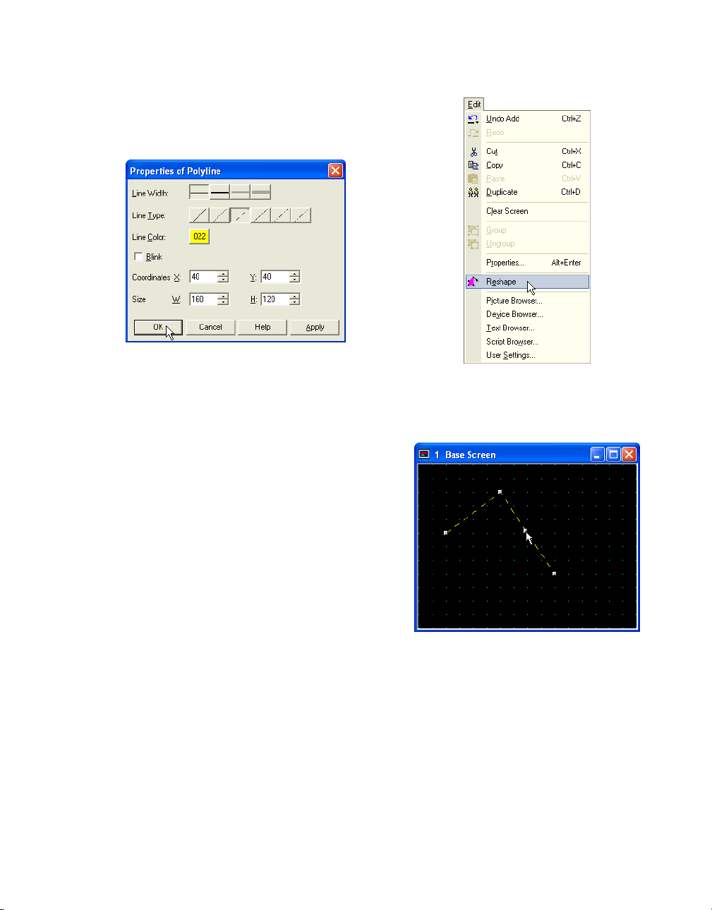
2.1.4 Changing Polyline Properties
If you want to change the properties of this
object after drawing, please select and doubleclick on it. The properties dialog box will appear.
Select a [Line Width]. In this case, select "1
dot".
Select a [Line Type]. In this case, select "Dash".
Click [Line Color]. The Color Palette will appear.
In this case, select the yellow "022".
If you want this object to blink check the [Blink]
box. In this case, leave it off. (Refer to the
Instruction Manual for more information on the
blincking cycle.)
2.1.5 Adding Apexes to a Polyline
Select the polyline and click the [Reshape] button on the tool bar (or select this object and
select [Edit] [Reshape] from the menu).
The Coordinates box will show the upper left
point of the rectangle area that surrounds the
drawing object and the Size shows the width
and the height of the rectangle area.
Click [OK].
A scale pointer will appear at each apex. Click
and hold the Ctrl key at the point on the line
where you want to add an apex.
2-3
Page 52

How to Use Objects
Double-click when done. After modifying, the
scale pointer will appear to enclose the points
in a rectangle.
2.1.6 Modifying Apex Location on a Polyline
Click the [Reshape] button on the tool bar (or
select this object and [Edit] [Reshape] from the
menu).
The scale pointer will appear at each apex and
the icon image changes to the mode for changing the shape on the apex.
Click and drag the apex where you want to on
the screen to change the shape.
2-4
Double-click when done. After modifying, the
scale pointer will appear to enclose the object
with a rectangle.
Page 53
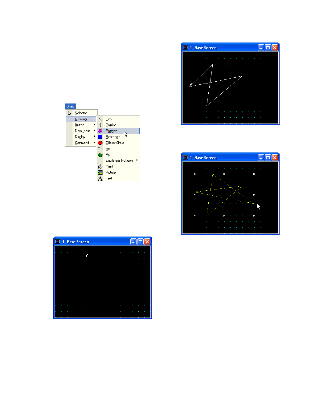
2.1.7 Drawing a Polygon
The default settings will be the same as the previously drawn object.
Tutorial: You will draw a polygon on Base
Screen 1. After drawing, you will change the
polygon properties so that the width of the line
is 3 dots, the color is green, and the design is a
vertical green with yellow stripe.
Click the [Polygon] button on the toolbar (or
select [Draw] [Drawing] [Polygon] from the
menu).
Drawing
Click on the screen at each point that you want
a corner in your object.
The icon image will change to the mode for
drawing an object.
Click the point on the screen where you want
the starting point to be.
Double-click when done. After drawing, the
scale pointer will appear to enclose the object
with a rectangle.
2-5
Page 54
How to Use Objects
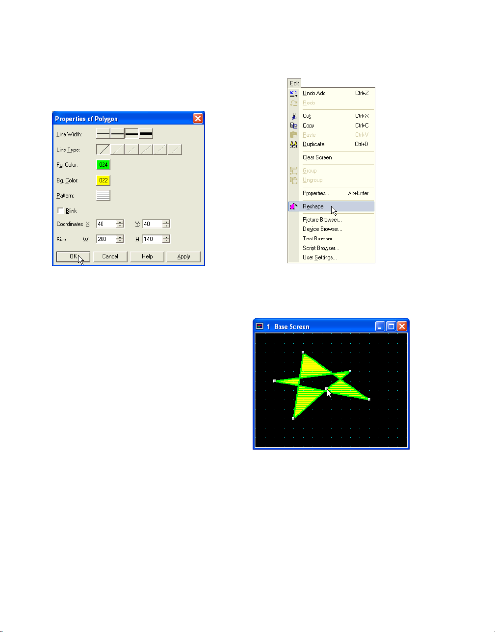
2.1.8 Changing Polygon Properties
To change the properties of this object after
drawing, please select and double-click the
object. The properties dialog box will appear.
Select a [Line Width]. In this case, click "3
dots".
Select a [Line Type]. In this case, "Solid" is
selected automatically. When you select "3
dots" or "5 dots" in [Line Width], you can only
use "Solid".
2.1.9 Adding Apexes to a Polygon
Select the polygon and click the [Reshape] button on the tool bar (or select this object and
[Edit] [Reshape] from the menu).
Click [Fg. Color]. The Color Palette will appear.
In this case, select the green "024".
Click [Bg. Color]. The Color Palette will appear.
In this case, select the yellow "022".
Click [Pattern]. The Pattern Palette will appear.
In this case, select "Vertical Stripe".
If you want this object to blink check the [Blink]
box. In this case, leave it off. (Refer to the
Instruction Manual for more information on the
blincking cycle.)
The Coordinates show the upper left point of
the rectangle area that surrounds the object.
The Size shows the width and height of the
rectangle area.
Click [OK].
2-6
The scale pointer will appear at each apex.
Click and hold the Ctrl key at the point on the
line where you want to add an apex.
Page 55

Drawing
Double-click when done. After modifying, the
scale pointer will appear to enclose the object
with a rectangle.
2.1.10 Modifying Apex Location on a
Polygon
Click the [Reshape] button on the tool bar (or
select this object and [Edit] [Reshape] from the
menu).
The scale pointer will appear at each apex and
the icon image changes to the mode for changing the shape of the apex.
Click and drag the apex where you want on the
screen to change the shape of the object.
Double-click when done. After modifying, the
scale pointer will appear to enclose the object
with a rectangle.
2-7
Page 56

How to Use Objects
2.1.11 Drawing a Rectangle
The default settings will be the same as the previously drawn object.
Tutorial: You will draw a rectangle on Base
Screen 1. After drawing, you will change the
properties of the rectangle so that the width of
the line is 1 dot, it will be cyan and the pattern
will be a long dashed line. The coordinates of
the upper left point will be (20, 20), the width
and the height will be 200, and the design will
be a horizontal cyan with blue stripe.
Click on the screen at the point where you want
to the upper left of the rectangle and drag the
pointer diagonally.
2.1.12 Changing Rectangle Properties
If you want to change the properties of this
object after drawing, please select and doubleclick the object. The properties dialog box will
appear.
Click the [Rectangle] button on the toolbar (or
select [Draw] [Drawing] [Rectangle] from the
menu).
The icon image will change to the mode for
drawing an object. Double-click the [Rectangle]
button on the toolbar if you want to draw more
than one rectangle with the same style. You can
continue to draw rectangles without selecting
the button on the toolbar.
2-8
Select a [Line Width]. In this case, select "1
dot".
Select a [Line Type]. In this case, select "Long
Dash".
Page 57

Click [Fg. Color]. The Color Palette will appear.
In this case, select the color cyan "026".
Click [Bg. Color]. The Color Palette will appear.
In this case, select blue "028".
Click [Pattern]. The Pattern Palette will appear.
In this case, select "Horizontal Stripe".
If you want this object to blink check the [Blink]
box. In this case, leave it off. (Refer to the
Instruction Manual for more information on the
blincking cycle.)
Drawing
Select [Round Type]. In this case, select
"Curve”.
Enter a value in [Round Radius]. In this case,
enter "20”.
The Coordinates show the upper left point of
this object. Enter coordinates in the [X] and [Y]
boxes. In this case, enter "(20, 20)".
The Size shows the width and the height of this
object. Enter the size in the [W] and [H] boxes.
In this case, enter "(200, 200)".
Click [OK].
2.1.13 Drawing a Circle or an Ellipse
The default settings will be the same as the previously drawn object.
Tutorial: You will draw an ellipse on Base
Screen 1. After drawing, you will change the
properties so that the line width is 1 dot, it is
blue and has a dashed pattern, the coordinates
of the upper left point will be (20, 20), the width
and height will be 200, and the design will be
blue and cyan diagonal lines.
Click the [Circle/Ellipse] button on the toolbar
(or select [Draw] [Drawing] [Circle/Ellipse] from
the menu).
The icon image will change to the mode for
drawing an object. Double-click the [Circle/
Ellipse] button on the toolbar to draw more than
one line with the same style. You can then continue to draw circles or ellipses without selecting the button on the toolbar.
Click the point on the screen where you want
the upper left point of the object to be and drag
the pointer diagonally. After dragging, an ellipse
that is surrounded by a rectangle area will
appear.
2-9
Page 58
How to Use Objects
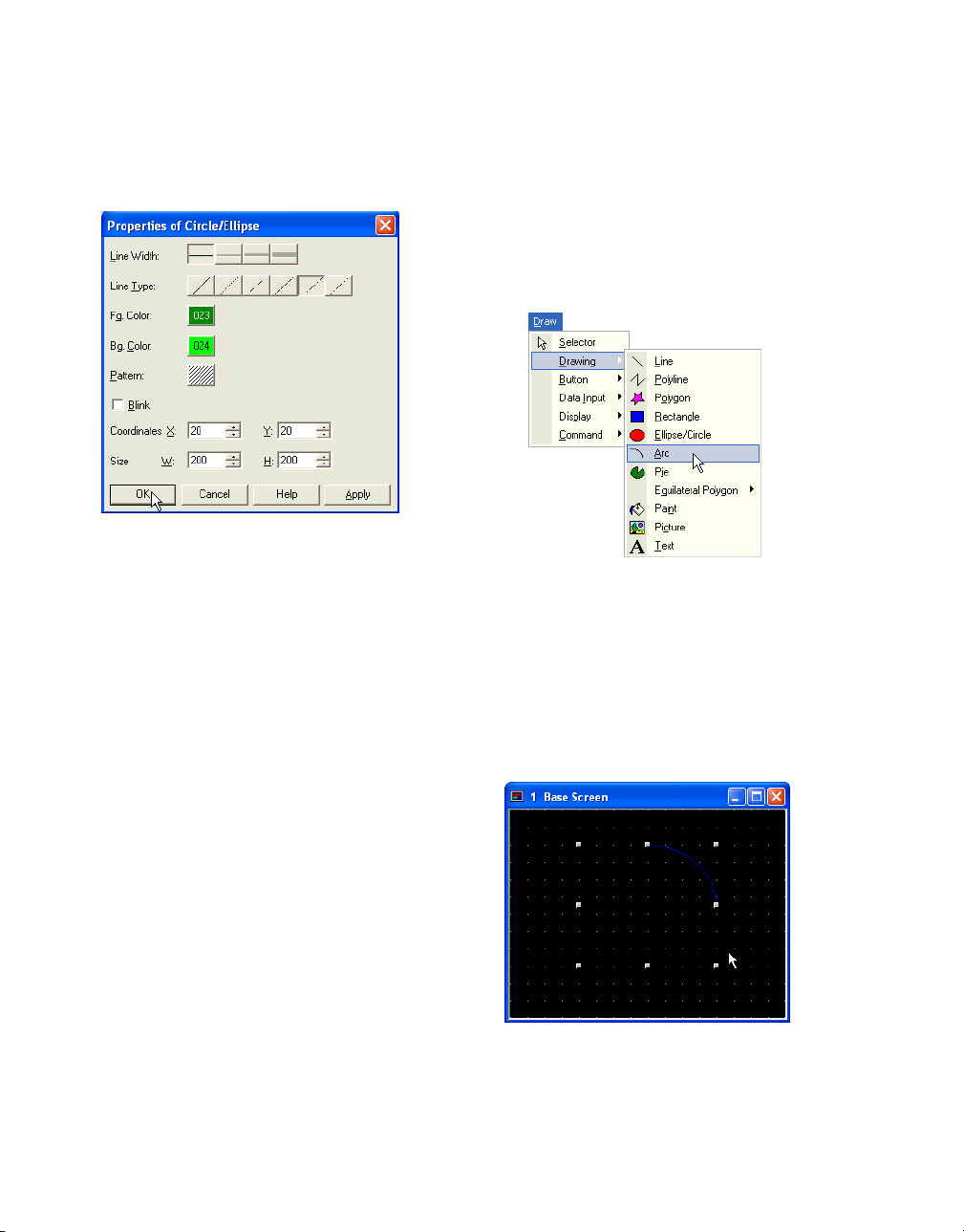
2.1.14 Changing the Properties of a Circle or an Ellipse
To change the properties of this object after
drawing, please select and double-click it.
The properties dialog box will appear.
Select a [Line Width]. In this case, select "1
dot".
Select a [Line Type]. In this case, select "Long
Dash Dot".
Click [Fg. Color].The Color Palette will appear.
In this case, select blue "023".
Click [Bg. Color]. The Color Palette will appear.
In this case, select cyan "024".
Click [Pattern]. The Pattern Palette will appear.
In this case, select "Up Diagonal".
2.1.15 Drawing an Arc
The default settings will be the same as the previously drawn object.
Tutorial: You will draw an arc on Base Screen 1.
After drawing, you will change the properties so
that he width of the line is 1 dot, the line is
magenta, the pattern is the long dash, the coordinates of the upper left point will be 20, 20, the
width is 200 and the height is 200.
Click the [Arc] button on the toolbar (or select
[Draw] [Drawing] [Arc] from the menu).
The icon image will change to the mode for
drawing an object.
Double-click the [Arc] button on the toolbar on
the toolbar to draw more than one object with
the same style. You can continue to draw arcs
without selecting the button on the toolbar.
If you want this object to blink check the [Blink]
box. In this case, leave it off. (Refer to the
Instruction Manual for more information on the
blincking cycle.)
The Coordinates show the upper left point of
this object. Enter the coordinates in the [X] and
[Y] boxes. In this case, enter "(20, 20)".
The Size shows the width and the height of this
object. Enter the size in the [W] and [H] boxes.
In this case, enter "(200, 200)".
Click [OK].
2-10
Click the point on the screen where you want
the upper left of the object to be and drag the
pointer diagonally. After dragging, a quarter of
an arc that is surrounded by a rectangle area
will appear.
Page 59

Drawing
2.1.16 Changing Arc Properties
To change the properties of this object after
drawing, please select and double-click the
object. The properties dialog box will appear.
Select a [Line Width]. In this case, select "1
dot".
Select a [Line Type]. In this case, select "Long
Dash Dot Dot".
Click [Line Color]. The Color Palette will appear.
In this case, select magenta "030".
If you want this object to blink check the [Blink]
box. In this case, leave it off. (Refer to the
Instruction Manual for more information on the
blincking cycle.)
2.1.17 Modifying the Starting or Ending Point of an Arc
To modify the location of an arc after drawing,
please select the object and click on the
[Reshape] menu. The scale pointer will appear
at each point so that you can move them.
Click the [Reshape] button on the tool bar (or
select this object and [Edit] [Reshape] from the
menu).
The Coordinates show the upper left point of
this object. Enter the coordinates in the [X] and
[Y] boxes. In this case, enter "(20, 20)".
The Size shows the width and the height of this
object. Enter the size in the [W] and [H] boxes.
In this case, enter "(200, 200)".
Click [OK].
The scale pointer will appear each point and
the icon image changes to the mode for changing the location of the point.
2-11
Page 60
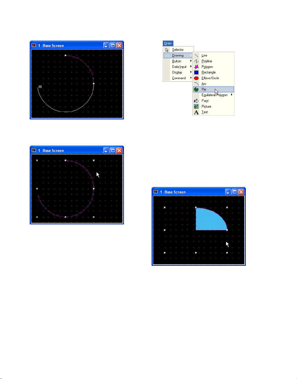
How to Use Objects
Click on the screen and drag the point to
change its location.
Double-click when done. After modifying, the
scale pointer will appear to surround the object
with a rectangle.
2.1.18 Drawing a Pie
The default settings will be the same as the previously drawn object.
Tutorial: You will draw a pie on Base Screen 1.
After drawing, you will change the properties so
that the width of the line is 5 dots, the color is
red, the coordinates of the upper left point will
be (20, 20), the width is 240, the height is 100
and the pattern will be a red with light grey
down diagonal.
Click the [Pie] button on the toolbar (or select
[Draw] [Drawing] [Pie] from the menu).
The icon image will change to the mode for
drawing an object. Double-click the [Pie] button
on the toolbar to draw more than one object
with the same style. You can continue to draw
pie objects without selecting the button on the
toolbar.
Click the point on the screen where you want
the upper left point of the pie to be and drag the
pointer diagonally. After dragging, a quarter of a
pie that is surrounded with a rectangle will
appear.
2-12
Page 61
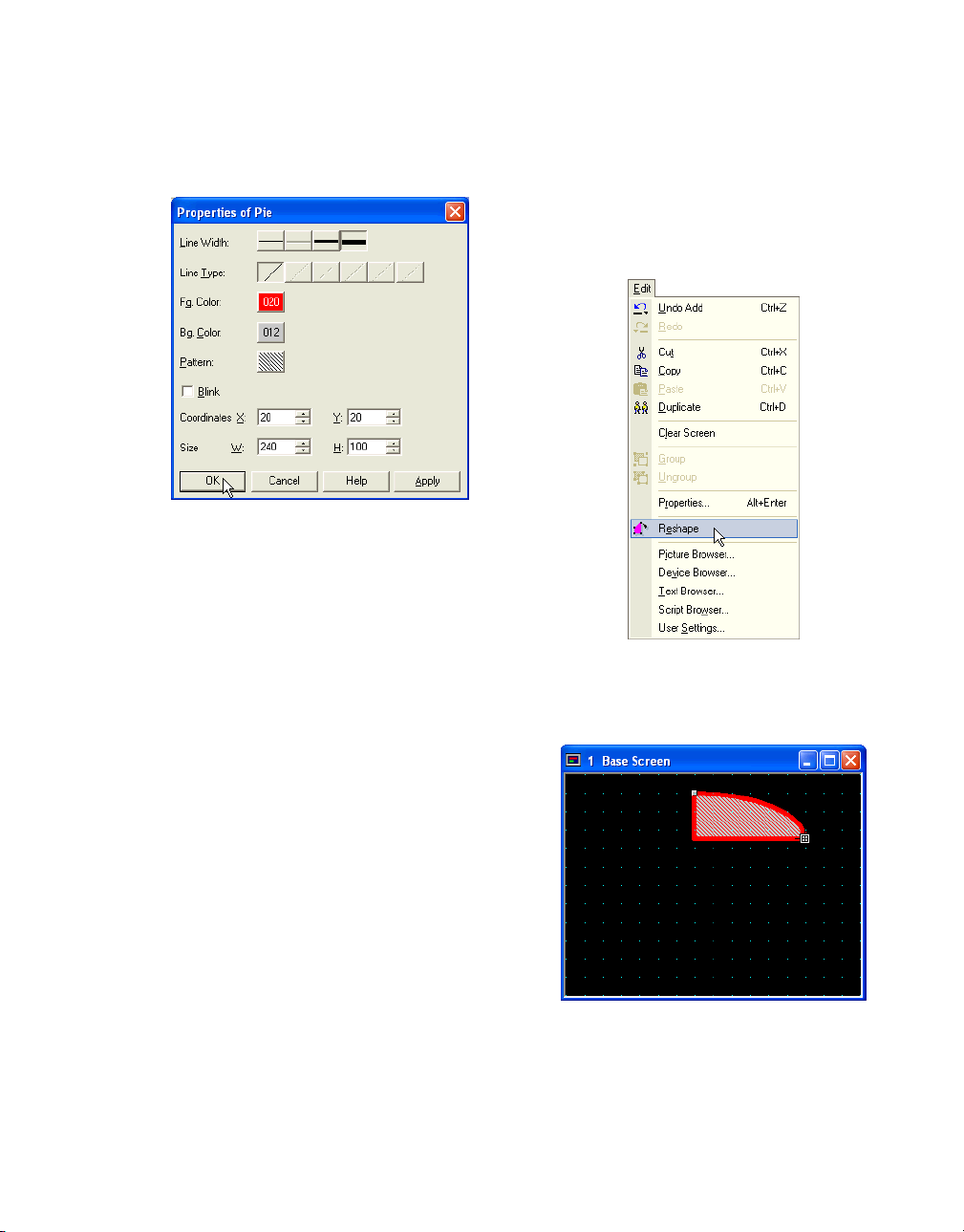
Drawing
2.1.19 Changing Pie Properties
To change the properties of this object after
drawing, please select and double-click it.
The properties dialog box will appear.
Select a [Line Width]. In this case, click "5 dots".
Select a [Line Type]. In this case, "Solid" is
selected automatically. When you select "3
dots" or "5 dots" in [Line Width], you can use
"Solid" only.
Click [Fg. Color]. The Color Palette will appear.
In this case, select red "020".
Click [Bg. Color]. The Color Palette will appear.
In this case, select light grey "012".
2.1.20 Modifying the Starting or Ending Points of a Pie
To modify the location of a point on a pie object
after drawing, please select the object and the
[Reshape] menu. The scale pointer will appear
at each the pie’s points and you can then
change the location of any point.
Click the [Reshape] button on the tool bar (or
select this object and [Edit] [Reshape] from the
menu).
Click [Pattern]. The Pattern Palette will appear.
In this case, select "Down Diagonal".
If you want this object to blink check the [Blink]
box. In this case, leave it off. (Refer to the
Instruction Manual for more information on the
blincking cycle.)
The Coordinates show the upper left point of
this object. Enter the coordinates in the [X] and
[Y] boxes. In this case, enter "(20, 20)".
The Size shows the width and the height of this
object. Enter the size in the [W] and [H] boxes.
In this case, enter "(240, 100)".
Click [OK].
The scale pointer will appear each point and
the icon image changes to the mode for changing the location of the point.
2-13
Page 62
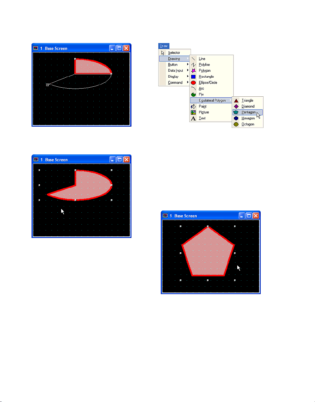
How to Use Objects
Click and drag the point on the screen to where
you want it to be.
Double-click when done. After modifying, the
scale pointer will appear to enclose the points
with a rectangle.
2.1.21 Drawing an Equilateral Polygon
The default settings will be the same as the previously drawn object.
Tutorial: You will draw an equilateral pentagon
on Base Screen 1. After drawing, you will
change the properties so that the width of the
line is 2 dots, it is dark cyan and dashed, the
coordinates of the upper left point will be (20,
20), the width will be 200, the height is 200 and
the design will be a dark cyan and cyan grid.
Click the [Equilateral Pentagon] button on the
toolbar (or select [Draw] [Drawing] [Equilateral
Polygon] [Pentagon] from the menu).
The icon image will change to the mode for
drawing an object. Double-click the [Equilateral
Pentagon] button on the toolbar to draw more
than one pentagon in the same style. You can
continue to draw equilateral pentagons without
selecting the button on the toolbar.
Click the point on the screen where you want
the upper left point of the pentagon to be and
drag the pointer diagonally. After dragging, the
pentagon will be surrounded by a square.
2-14
Page 63
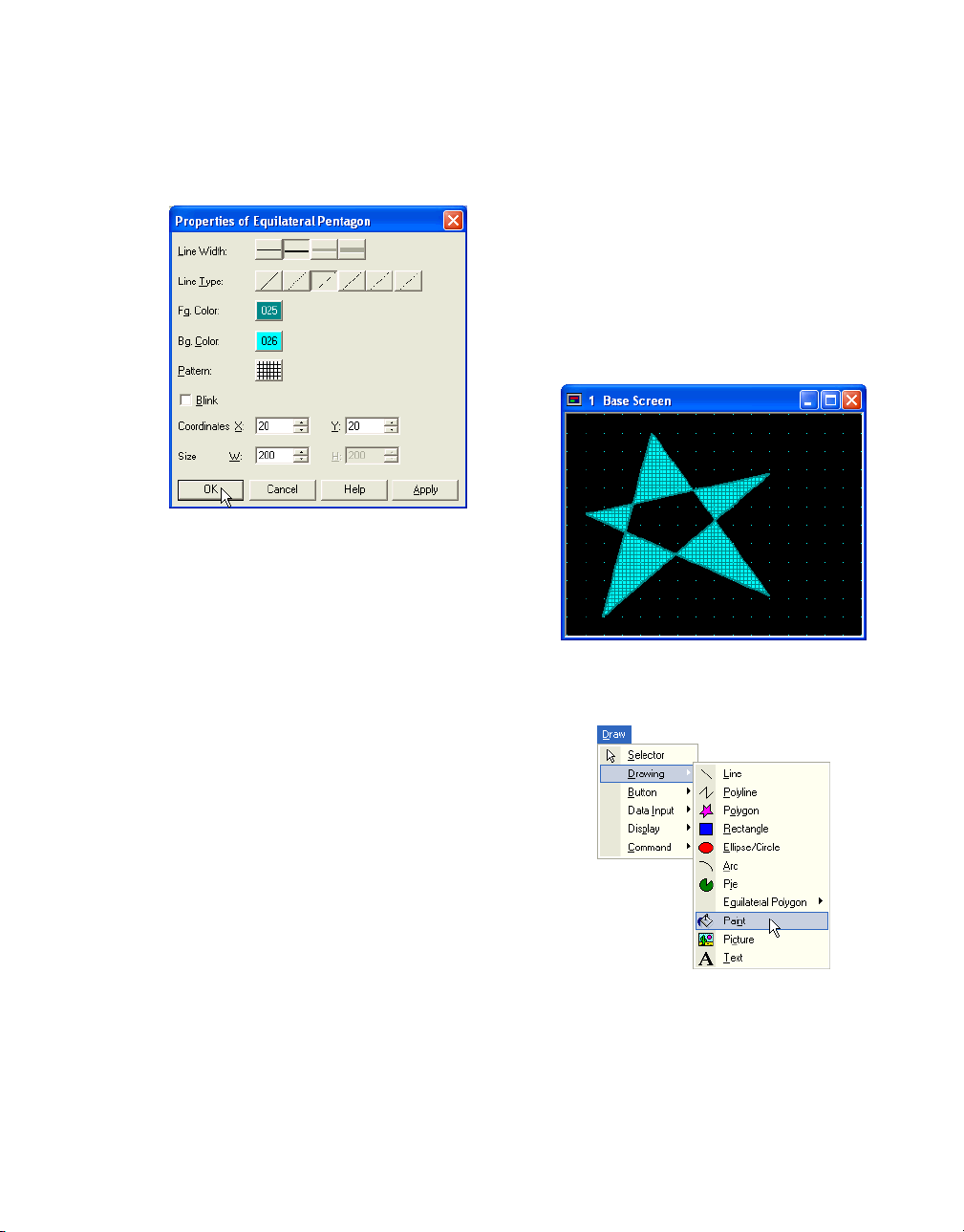
Drawing
2.1.22 Changing Pentagon Properties
To change the properties of this object after
drawing, please select and double-click it.
The properties dialog box will appear.
Select a [Line Width]. In this case, click "2
dots".
Select a [Line Type]. In this case, click "Dash"
button.
Click [Fg. Color]. The Color Palette will appear.
In this case, select dark cyan "025".
Click [Bg. Color]. The Color Palette will appear.
In this case, select cyan "026".
2.1.23 Using Fill Color
If the object being filled with color has any
openings in its border, the fill color will go
beyond the borders into the rest of the drawing
area. The default is set the same as the previously drawn object.
Tutorial: You will fill the center area of the polygon on Base Screen 1 with color. After drawing,
you will change the properties so that the coordinates will be (100,100) and the design will be
a dark yellow and yellow trellis.
Draw a polygon. For more information, see
“Drawing an Equilateral Polygon” on page 2-14.
Click [Pattern]. The Pattern Palette will appear.
In this case, select "Grid".
If you want this object to blink check the [Blink]
box. In this case, leave it off. (Refer to the
Instruction Manual for more information on the
blincking cycle.)
The Coordinates show the upper left point of
this object. Enter coordinates in the [X] and [Y]
boxes. In this case, enter "(20, 20)".
The Size shows the width and the height of this
object. Enter the size in the [W] and [H] boxes.
In this case, enter "(200, 200)".
Click [OK].
Click the [Paint] button on the toolbar (or select
[Draw] [Drawing] [Paint] from the menu).
The icon image will change to the mode for filling an area with color. Double-click the [Paint]
button on the toolbar.
2-15
Page 64

How to Use Objects
Click the area you want to fill with color.
2.1.24 Changing Color Properties
To change the properties of this object after
drawing, please select and double-click it.
The properties dialog box will appear.
2.2 Setting Appearances & Trigger Condition
Selecting the Shape of a Button or
Pilot Lamp
You can select an image from the standard or
registered images.
2.2.1 Selecting a Standard Image
Tutorial: You will set a Bit Button on Base
Screen 1 using a standard image.
Click [Fg. Color].The Color Palette will appear.
In this case, select “dark yellow ".
Click [Bg. Color]. The Color Palette will appear.
In this case, select yellow "022".
Click [Pattern]. The Pattern Palette will appear.
In this case, select "Trellis".
Enter coordinates in the [X] and [Y] boxes. In
this case, enter "(100, 100)".
Click [OK].
2-16
Create a Bit Button. For more information see
“Writing to a Bit with a Button” on page 2-31.
Double-click the selected object after placing
on the screen. The properties dialog box will
appear.
Click [View] tab.
Page 65
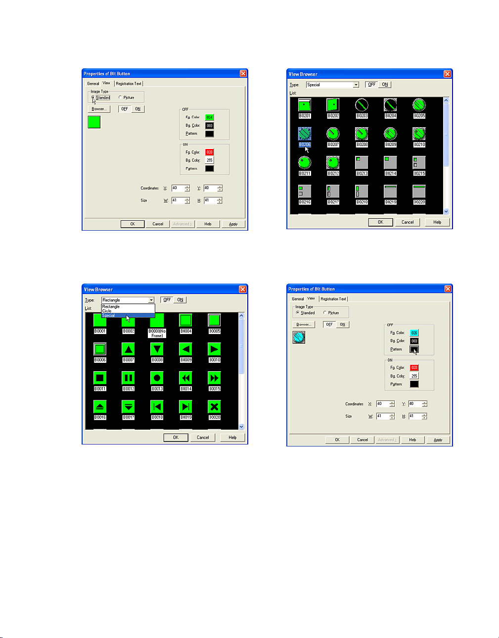
Setting Appearances & Trigger Condition
Select an [Image Type]. In this case, select
"Standard" because you will use a standard
image.
Click [Browser]. The View Browser dialog box
will appear.
Select a [Type]. In this case, select "Special".
When you click the [OFF] or [ON] button, you
can see the button image for each state.
Select an image from the [List] box. In this
case, select "B0206" and click [OK]. This image
will be displayed on the View tab.
Set a color for the OFF state of the image in the
[OFF] box.
Click [Fg. color]. The Color Palette will appear.
In this case, select cyan "026".
Click [Bg. color]. The Color Palette will appear.
In this case, select a black "000".
Click [Pattern]. The Pattern Palette will appear.
In this case, select "Fore100%".
2-17
Page 66

How to Use Objects
The image will be displayed with the above settings when the OFF button is selected.
Set a color for the ON image by clicking the
[ON] box.
Click [Fg. color]. The Color Palette will appear.
In this case, select a magenta "030".
Click [Bg. Color]. The Color Palette will appear.
In this case, select a white "255".
Click [Pattern]. The Pattern Palette will appear.
In this case, select "Fore100%".
2.2.2 Selecting a Registered Image
Tutorial: You will set a Pilot Lamp on Base
Screen 1 using a bitmap file for the image of the
button. The two bitmap files ("sq01_b.bmp" and
"sq06_b.bmp") are registered to Picture
Browser. For more information, see “Arranging
Images with Picture Browser” on page 3-1.
Create a Pilot Lamp. For more information see
“Setting a Pilot Lamp” on page 2-106.
Double-click the selected object after placing
on the screen. The properties dialog box will
appear.
Click [View] tab.
The image will be displayed with the above settings when the ON button is selected.
Click [OK].
If everything has been set, this dialog box will
close and the OFF image appears on the
screen.
2-18
Select an [Image Type]. In this case, select
"Picture" because you will use a bitmap file.
Page 67

Setting Appearances & Trigger Condition
Click the [OFF] button to set an image for the
button in the OFF state.
Click [Browser]. The Picture Browser dialog box
will appear. In this case, select "dm33_g" and
click [Select]. This image is set for the OFF
state.
Click the [ON] button to set an image for the ON
state.
Click [Browser]. The Picture Browser dialog box
will appear. In this case, select "dm36_g" and
click [Select]. This image is set for the ON state.
Click [OK].
If everything has been set, this dialog box will
close and the OFF image appears on the
screen.
2-19
Page 68
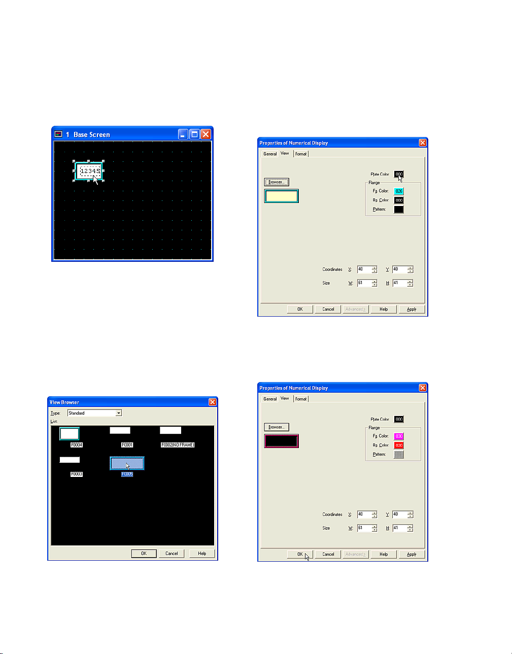
How to Use Objects
2.2.3 Selecting the Shape of a Plate or Flange
Tutorial: You will set a Numerical Display on
Base Screen 1 using standard images.
Create a Numerical Display. For more information see “Displaying Numerical Values” on
page 2-63.
Double-click the selected object after placing
on the screen. The properties dialog box will
appear.
Click [View] tab.
You don’t need to select a type from the [Type]
list. In this case, this object is "Standard".
Select an image from the [List] box. In this
case, select "F0005" and click [OK]. This image
will be displayed on the View tab.
Click [Plate Color]. The Color Palette will
appear.
In this case, select black "000". The image on
the View tab will be displayed with this color.
Click [Browser]. The View Browser dialog box
will appear.
2-20
Set a color for flange in the [Flange] box. If you
select an image without a flange, you don’t
need to change these settings.
Page 69
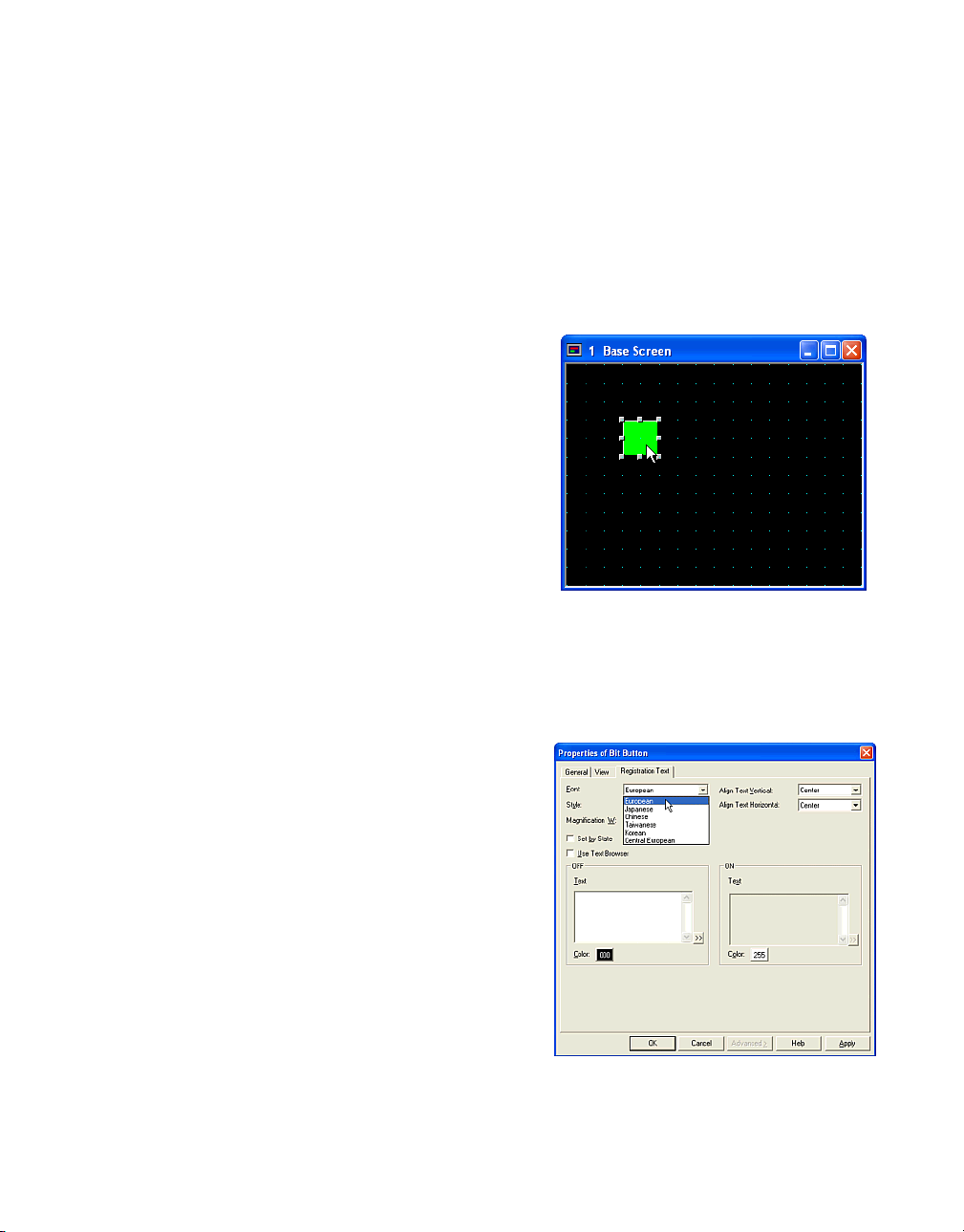
Setting Appearances & Trigger Condition
Click [Fg. color]. the Color Palette will appear.
In this case, select magenta "030".
Click [Bg. Color]. The Color Palette will appear.
In this case, select red "020.
Click [Pattern]. The Pattern Palette will appear.
In this case, select "Trellis".
The image on the View tab will be displayed
with the above settings when you select an
image with a flange.
Click [OK].
If everything has been set, this dialog box will
close and the image will appear on the screen.
2.2.4 Setting Registration Text
Tutorial: You will create a Bit Button on Base
Screen 1. The registration text will be blue (028)
and read "OFF" when the button is OFF. The
registration text will be red (020) and read “ON”
when the button is "ON". The font will be "European", the style will be "Bold", the horizontal
text alignment will be "Top", the vertical will be
"Left" and the magnification will be "1x0.5"
(WxH).
Create a Bit Button. For more information see
“Writing to a Bit with a Button” on page 2-31.
Double-click the selected object after placing
on the screen. The properties dialog box will
appear.
Click [Registration Text] tab.
2-21
Page 70

How to Use Objects
Select a [Style]. In this case, select "Bold".
Select a magnification from the [W] and [H]
boxes. In this case, select "1" in [W] and "0.5"
in [H].
Select the alignment from [Align Text Vertical]
and [Align Text Horizontal] pull down text
boxes. In this case, select "Top" in [Align Text
Vertical] and "Left" in [Align Text Horizontal].
Check [Set by State]. (If you are going to use
same text for both OFF and ON states, it isn’t
necessary to check this box.)
2-22
Page 71

If you want to use already registered text from
the Text Browser, check the [Use Text Browser]
box. (The Text ID settings will appear. Enter the
ID number of the registered text or click the […]
button to use the Text Browser. You can select
the desired text by clicking [Select]. Then the
Text Browser will close, the selected text ID will
appear in the Text ID box, and the corresponding text will appear in the text box.)
Enter registration text in the “OFF” [Text] box.
In this case, enter "OFF".
Setting Appearances & Trigger Condition
Enter registration text in the “ON” [Text] box.
(If you use the same text for both OFF and ON
states, it isn’t necessary to enter text in both
boxes.)
In this case, enter "ON". If you want to use a
special character, click the ">>" button. (The
Unicode Input dialog box will appear. You can
input characters from languages other than the
OS language. See the Instruction Manual for
details.)
If you want to use a special character, click the
">>" button. (The Unicode Input will appear.
You can input characters from languages other
than the OS language. See the Instraction Manual for details.)
Select a [Color]. The Color Palette will appear.
In this case, select blue "028".
Select a [Color]. The Color Palette will appear.
In this case, select red "020".
Click [OK].
If everything has been set, this dialog box will
close and the OFF state of the image with the
registration text appears on the screen.
2-23
Page 72

How to Use Objects
2.2.5 Setting the Display Text Format
Tutorial: You will set a Message Display on
Base Screen 1. The font will be "European", the
style will be "Regular", the magnification will be
"2x2" (WxH),), the horizontal and vertical text
alignment will be "Center" and the text color will
be magenta (030).
Create a Message Display. For more information see “Displaying and Loading Messages” on
page 2-80.
Double-click the selected object after placing
on the screen. The properties dialog box will
appear.
.
Select a [Font]. In this case, select "European"
Click [Format] tab.
2-24
Select a [Style]. In this case, select "Regular".
Select a magnification in the [W] and [H] boxes.
In this case, select "2" in [W] and "2" in [H].
Page 73

Select the alignment from the [Align Text Vertical] and [Align Text Horizontal] boxes. In this
case, select "Center" in both.
Setting Appearances & Trigger Condition
2.2.6 Switching the Display Text
Tutorial: You will display text depending on the
value of a device. The value is stored in the HG
Internal Register (LDR1000). When LDR1000
is "1", the registered text will be displayed in
English, "2" will be "Japanese", "3" will be
"Spanish" and so on.
Select [Setup] [Text Group Settings] from the
menu.
Click [Text Color]. The Color Palette will appear.
In this case, select green "030".
Click [OK].
If everything has been set, this dialog box will
close and the object with the formatted text will
appear on the screen.
Enter the number of the text groups. In this
case, enter "5" because you will switch five text
groups.
2-25
Page 74
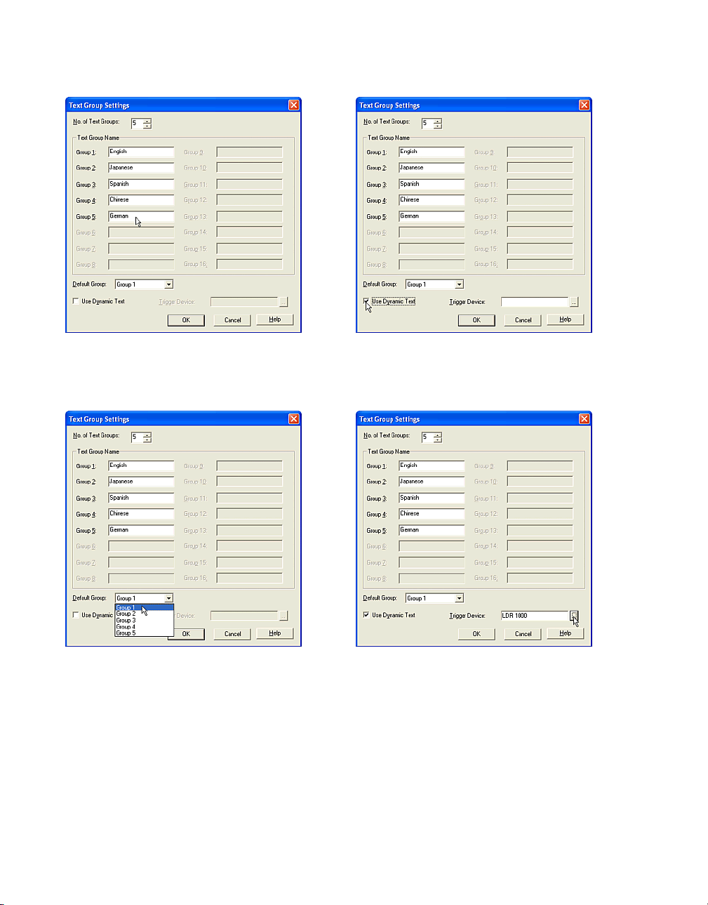
How to Use Objects
Enter a title to each group in the [Text Group
Name] box. In this case, enter "English" to
[Group1], "Japanese" to [Group2] and so on.
Select the [Default Group]. In this case, select
"Group 1".
The group number is linked to the value of the
trigger device. If the value is "0", the text of the
Default Group appears (Group 1). If the value is
a number that isn’t set as a group, the text will
not be switched.
Click [Use Dynamic Text]. This will allow you to
switch the text depend on the value of the trigger device.
Set a word device in the [Trigger Device] box.
In this case, enter "LDR 1000".
Click [OK].
2-26
Page 75

2.2.7 Setting the Coordinates of a Part
Object
Tutorial: You will set a Go To Screen Button on
Base Screen 1. You will then change the coordinates to "(40, 40)".
Create a Go To Screen Button. For more information see “Changing Screens with a Button”
on page 2-46.
Double-click on the selected object after placing on the screen. The properties dialog box will
appear.
Setting Appearances & Trigger Condition
If everything has been set, this dialog box will
close and the object at the specified coordinates will appear on the screen.
2.2.8 Setting the Size of a Part Object
Tutorial: You will set a Go To Screen Button on
Base Screen 1. You will change the size to "121
x 61".
Click [View] tab.
Enter a value in the [X] and [Y] boxes. In this
case, enter "260" in [X] and "180" in [Y].
Click [OK].
Create a Go To Screen Button. For more information see “Changing Screens with a Button”
on page 2-46.
Double-click the selected object after placing
on the screen. The properties dialog box will
appear.
Click [View] tab.
2-27
Page 76
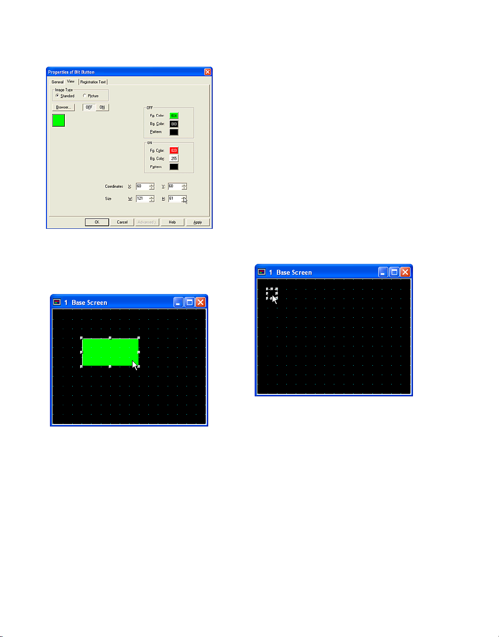
How to Use Objects
Enter a value in the [W] and [H] boxes. In this
case, enter "121" in [W] and "61" in [H].
Click [OK].
Setting a Trigger Condition for a
Command
When you use a Command object, you need to
set a trigger condition.The format depends on
the specified Trigger Type. The device address
must be specified and the condition must be
specified. For more information see “Setting a
Timer” on page 2-108.
2.2.9 Executing the Command According to the State of the Device
Tutorial: You will set a Go To Screen Command
on Base Screen 1. When the selected device
"HG Internal Relay (LM 0)" turns from 0 to 1,
the displayed screen changes from Base
Screen 1 to Base Screen 2.
If everything has been set, this dialog box will
close and the object with the specified size will
appear on the screen.
2-28
Create a Go To Screen Command. For more
information see “Using a Condition to Change
the Screen” on page 2-47.
Double-click the selected object after placing
on the screen. The properties dialog box will
appear.
Click [Trigger Condition] tab.
Page 77
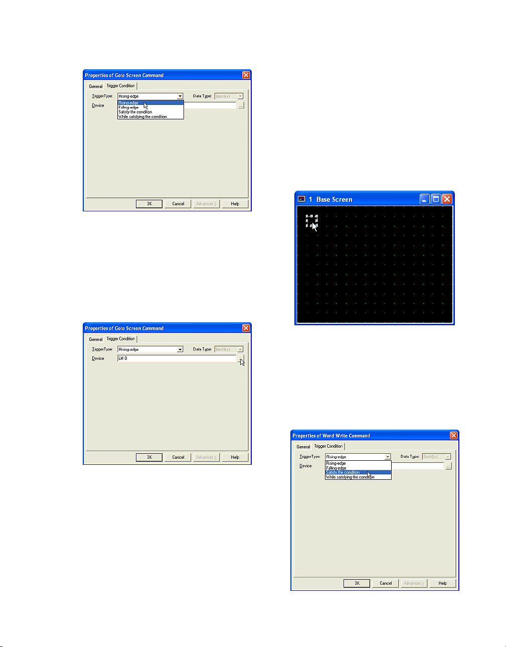
Select the condition from the [Trigger Type] list.
In this case, select "Rising-edge" because the
screen will switche when the selected bit device
turns from 0 to 1.
If you select "Falling-edge", the screen will
switch when the selected bit device turns from
1 to 0.
Setting Appearances & Trigger Condition
2.2.10 Executing the Command
According to the Defined Condition
Tutorial: You will set a Word Write Command on
Base Screen 1. When the sum of the value of
the HG Internal Register (LDR 10) and the
value of the HG Internal Register (LDR 20)
becomes more than 1000 (the numeric formula
for this condition is "1000 < [LDR 10] + [LDR
20] ".), the value of the HG Internal Register
(LDR 100) will be copied to the HG Internal
Register (LDR 1000).
Set the device that triggers the off action in
[Device]. In this case, enter "LM 0".
Click [OK].
If everything has been set, this dialog box will
close and the object with the specified settings
will appear on the screen.
Create a Word Write Command. For more information see “Copying Device Values with a
Command” on page 2-38.
Double-click the selected object after placing
on the screen. The properties dialog box will
appear.
Click [Trigger Condition] tab.
2-29
Page 78
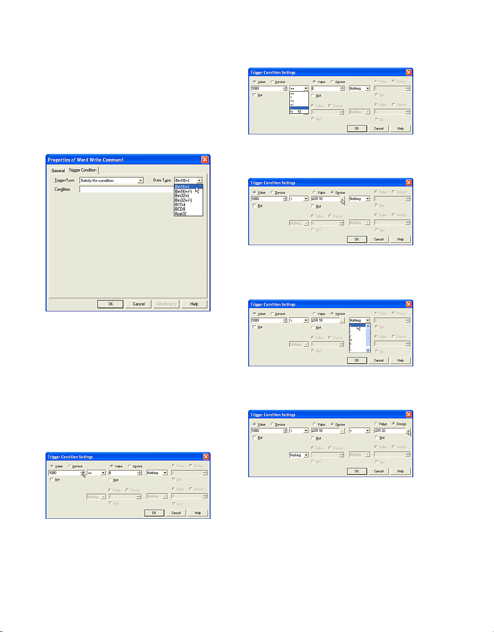
How to Use Objects
Select a [Trigger Type] list. In this case, select
"Satisfy the condition" because this command
is executed when the specified condition
becomes true.
If you select "While satisfy the condition", this
command will be executed when the specified
condition is true.
Select a symbol. In this case, select the less
than sign "<".
Select a type and set a value or device. In this
case, select "Device" and select (or type) "LDR
10".
Select a [Data Type]. This setting should be
selected according to the value of the [Condition]. In this case, select "Bin16(+)". This setting
depends on the value that you will use for the
condition.
Set a conditional expression in the [Condition]
box.
Click […]. The Trigger Condition Settings dialog
box will appear.
Select a type and set a value or device. In this
case, select "Value" and enter "1000".
2-30
Select a symbol. In this case, select a plus sign
"+".
Select a type and set a value or device. In this
case, select "Device" and select (or type) "LDR
20".
Select another symbol if you need to add an
additional condition. In this case, select "Noth-
ing" because you don’t need the additional condition.
Page 79
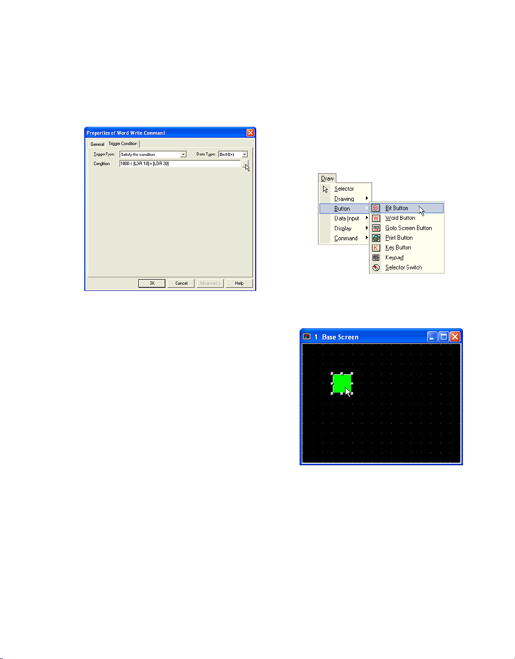
Writing to a Device
Check the [Not] box if you need them. In this
case, you don’t use them because you don’t
need to invert the bit.
Click [OK].
The settings in the Trigger Condition Settings
dialog box will appear in the [Condition] box. In
this case, "1000 < [LDR 10] + [LDR 20]" is
shown.
2.3 Writing to a Device
2.3.1 Writing to a Bit with a Button
Tutorial: You will create a button on Base
Screen 1. When the button is pressed, HG
Internal Relay (LM 0) will be written as 1. When
you release the button, it will be written as 0.
Click the [Bit Button] button on the toolbar (or
select [Draw] [Button] [Bit Button] from the
menu).
If you enter a conditional expression in the
[Condition] box directly, you have to put the
device in square brackets as shown above.
Click [OK].
If everything has been set, this dialog box will
close and the object with the specified settings
will appear on the screen.
Double-click the selected object after placing
on the screen. The properties dialog box will
appear.
2-31
Page 80
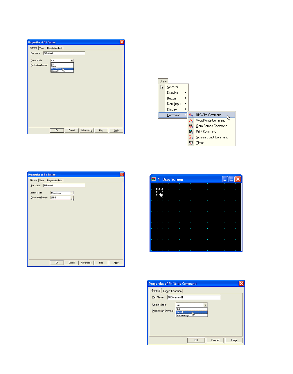
How to Use Objects
Select an [Action Mode]. In this case, select
"Momentary" because the selected bit device is
written as 1 when you press the button and is
written as 0 when you release it.
2.3.2 Writing to a Bit with A Command
Tutorial: When the HG Internal Relay (LM 0)
turns from 0 to 1, the HG Internal Register (LDR
0-0) is written as 0.
Click the [Bit Write Command] button on the
toolbar (or select [Draw] [Command] [Bit Write
Command] from the menu).
Set a bit device or a word device with bit in the
[Destination Device] box. In this case, enter
"LM 0".
Click [OK].
2-32
Double-click the selected object after placing
on the screen. The properties dialog box will
appear.
Page 81

Writing to a Device
Select an [Action Mode]. In this case, select
"Reset" because the selected device is written
as 0 when the condition specified in the Trigger
Condition occurs.
Set a bit device or a word device with bit to
[Destination Device] box. In this case, enter
"LDR 0-0".
Click [Trigger Condition] tab.
2.3.3 Writing to a Word Device with a Button
Tutorial: You will create a button on Base
Screen 1. When the button is pressed, the HG
Internal Register (LDR 100) will be written as
"1234567890".
Click the [Word Button] button on the toolbar (or
select [Draw] [Button] [Word Button] from the
menu).
Set the Trigger Condition. For more information
see “Setting a Trigger Condition” - “Executing
the Command According to the State of the
Device” on page 2-28. In this case, select "Ris-
ing-edge" in [Trigger Type] and enter "LM 0" as
the [Device].
Click [OK].
Double-click the selected object after placing
on the screen. The properties dialog box will
appear.
2-33
Page 82

How to Use Objects
Select an [Action Mode]. In this case, select
"Set" because the selected device writes the
specified value when you press the button.
Select a [Data Type]. In this case, select
"Bin32(+)" because you will enter
"1234567890" to the device.
Enter a value in the [Source Data] box. In this
case, enter "1234567890".
If you want to enter a Hexadecimal value,
select this check box.
Set a word device in the [Destination Device]
box. In this case, enter "LDR 100".
Click [OK].
2-34
Page 83

Writing to a Word Device using Word Write Command
2.3.4 Writing to a Word Device using
Word Write Command
Tutorial: You will specify a trigger condition
which when it is satisfied, the specified word
device is written with the specified value. For
example, when the HG Internal Relay (LM 0)
turns from 1 to 0, the HG Internal Register (LDR
100) will be written as "-987654321".
Click the [Word Write Command] button on the
toolbar (or select [Draw] [Command] [Word
Write Command] from the menu).
Select an [Action Mode]. In this case, select
"Set" because the selected device writes the
specified value when you press the button.
Double-click the selected object after placing
on the screen. The properties dialog box will
appear.
Select a [Data Type]. In this case, select
"Bin32(+/-)" because you will set "-987654321"
to the device.
2-35
Page 84
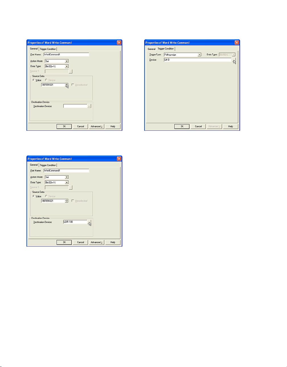
How to Use an Object
Enter a value in the [Source Data] box. In this
case, enter "-987654321".
Set a word device in the [Destination Device]
box. In this case, enter "LDR 100".
Click [Trigger Condition] tab.
Set the Trigger Condition. For more information
see “Setting a Trigger Condition” - “Executing
the Command According to the State of the
Device” on page 2-28. In this case, select "Fall-
ing-edge" in [Trigger Type] and enter "LM 0" as
the [Device].
Click [OK].
2-36
Page 85
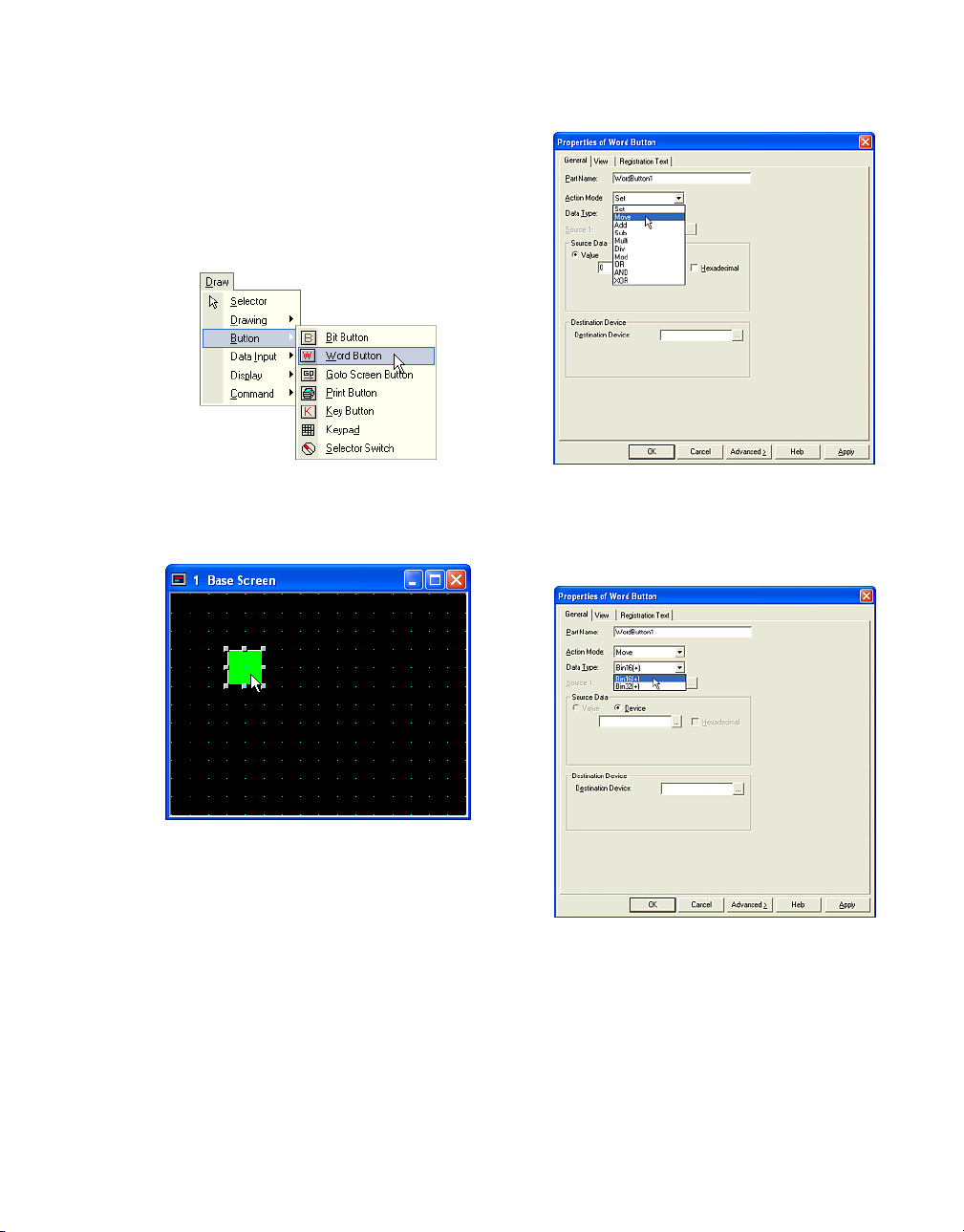
2.3.5 Copying the Device Values with a
Button
Tutorial: You will create a button on Base
Screen 1. When you press the button, the value
of the HG Internal Register (LDR 100) will be
copied to the HG Internal Register (LDR 1000).
Copying the Device Values with a Button
Click the [Word Button] button on the toolbar (or
select [Draw] [Button] [Word Button] from the
menu).
Double-click the selected object after placing
on the screen. The properties dialog box will
appear.
Select an [Action Mode]. In this case, select
"Move" because the value of the selected
device is copied to the specified device when
you press the button.
Select a [Data Type]. In this case, select
"Bin16(+)". (This setting is determined by the
type of value that you will copy.)
2-37
Page 86

How to Use an Object
Set a word device in the [Source Data] box. In
this case, enter "LDR 100".
2.3.6 Copying Device Values with a Command
Tutorial: You will specify a trigger condition that
when satisfied will copy the value of the specified word device to the specified device. For
example, when the sum of the value of the HG
Internal Register (LDR 10) and the value of the
HG Internal Register (LDR 20) is over 1000 (the
numeric formula for this condition is "1000 <
[LDR 10] + [LDR 20] ".), the value of the HG
Internal Register (LDR 100) will be copied to
the HG Internal Register (LDR 1000).
Set a word device in the [Destination Device]
box. In this case, enter "LDR 1000".
Click [OK].
2-38
Click the [Word Write Command] button on the
toolbar or select [Draw] [Command] [Word
Write Command] from the menu).
Double-click the selected object after placing
on the screen. The properties dialog box will
appear.
Page 87
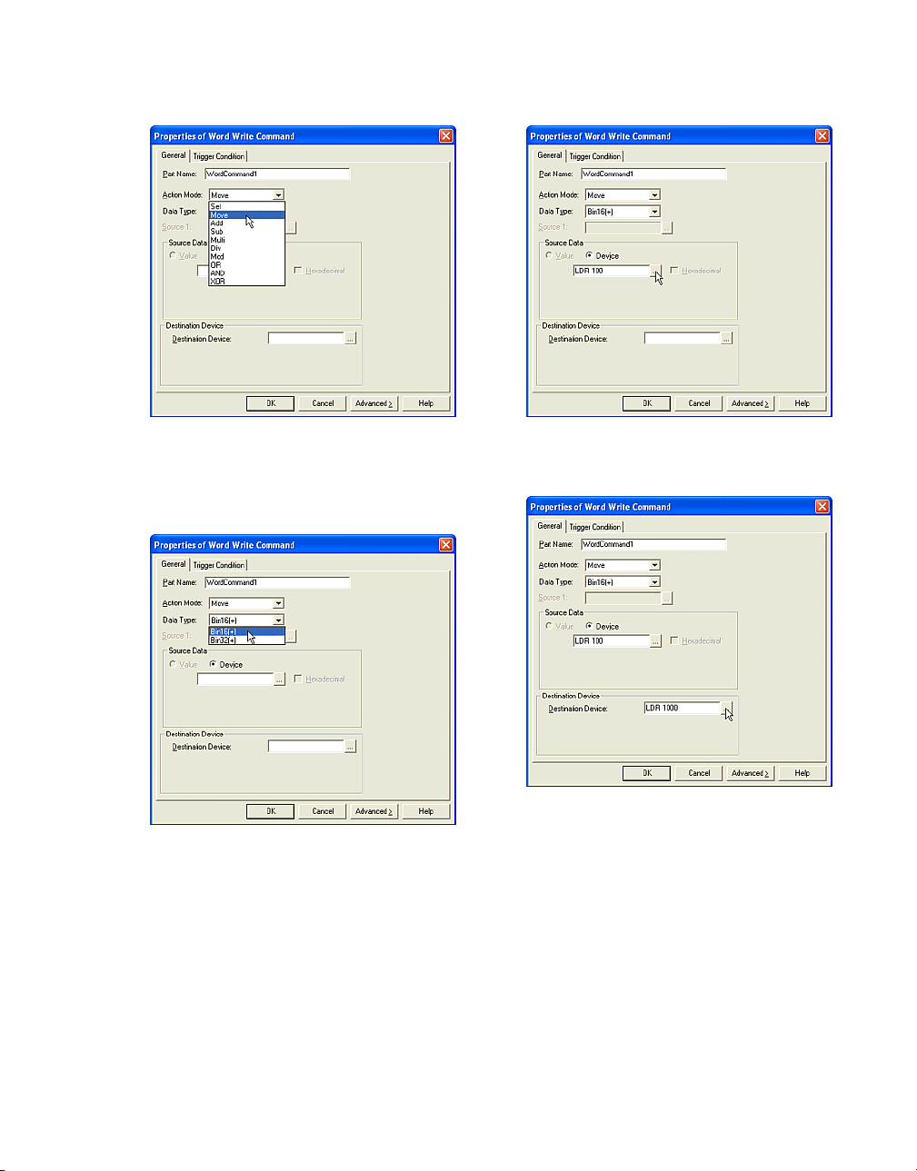
Copying Device Values with a Command
Select an [Action Mode]. In this case, select
"Move" because the value of the selected
device is copied to the specified device when
you press the button.
Select a [Data Type]. In this case, select
"Bin16(+)". (This setting is determined by the
type of value that you will copy.)
Set a word device in the [Source Data] box. In
this case, enter "LDR 100".
Set a word device to the [Destination Device]
box. In this case, enter "LDR 1000".
Click [Trigger Condition] tab.
2-39
Page 88
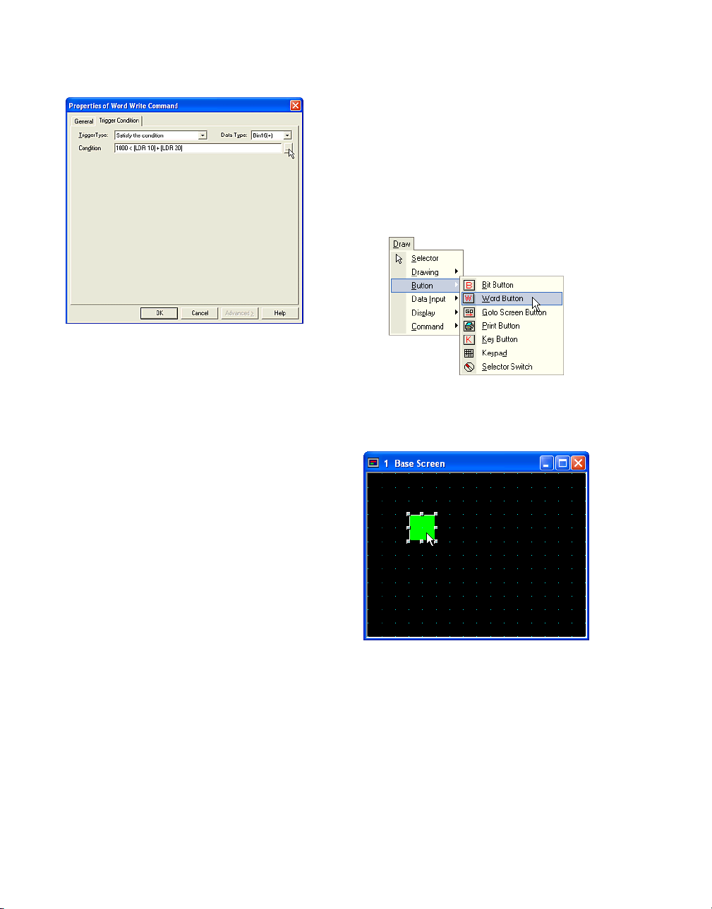
How to Use an Object
Set the Trigger Condition. For more information
see “Setting a Trigger Condition” - “Executing
the Command According to the State of the
Device” on page 2-28.In this case, select "Sat-
isfy the condition" in [Trigger Type], "Bin16(+)"
in [Data Type] and enter "1000 < [LDR 10] +
[LDR 20]" as the [Condition].
2.3.7 Writing a Calculation to a Word Device with a Button
Tutorial: When you press the button on a Base
Screen 1, the value of the HG Internal Register
(LDR 100) multiplied by 100 will be written to
the HG Internal Register (LDR 1000). The
numerical formula is "LDR 100 x 100 = LDR
1000".
Click the [Word Button] button on the toolbar (or
select [Draw] [Button] [Word Button] from the
menu).
If you enter a conditional expression in the
[Condition] box directly, you have to put the
device in square brackets as shown above.
Click [OK].
2-40
Double-click the selected object after placing
on the screen. The properties dialog box will
appear.
Page 89

Writing a Calculation to a Word Device with a Button
Select an [Action Mode]. In this case, select
"Multi" because the value of the selected device
will be multiplied by 100 when you press the
button.
Select a [Data Type]. In this case, select
"Bin16(+)". (This setting is determined by the
type of value that you will use for the condition.)
Set a word device in the [Source 1] box. In this
case, enter "LDR 100".
Select a type and set a word device in the
[Source2] box. In this case, select "Value" and
enter "100".
If you want to enter a hexadecimal value, select
this check box.
2-41
Page 90
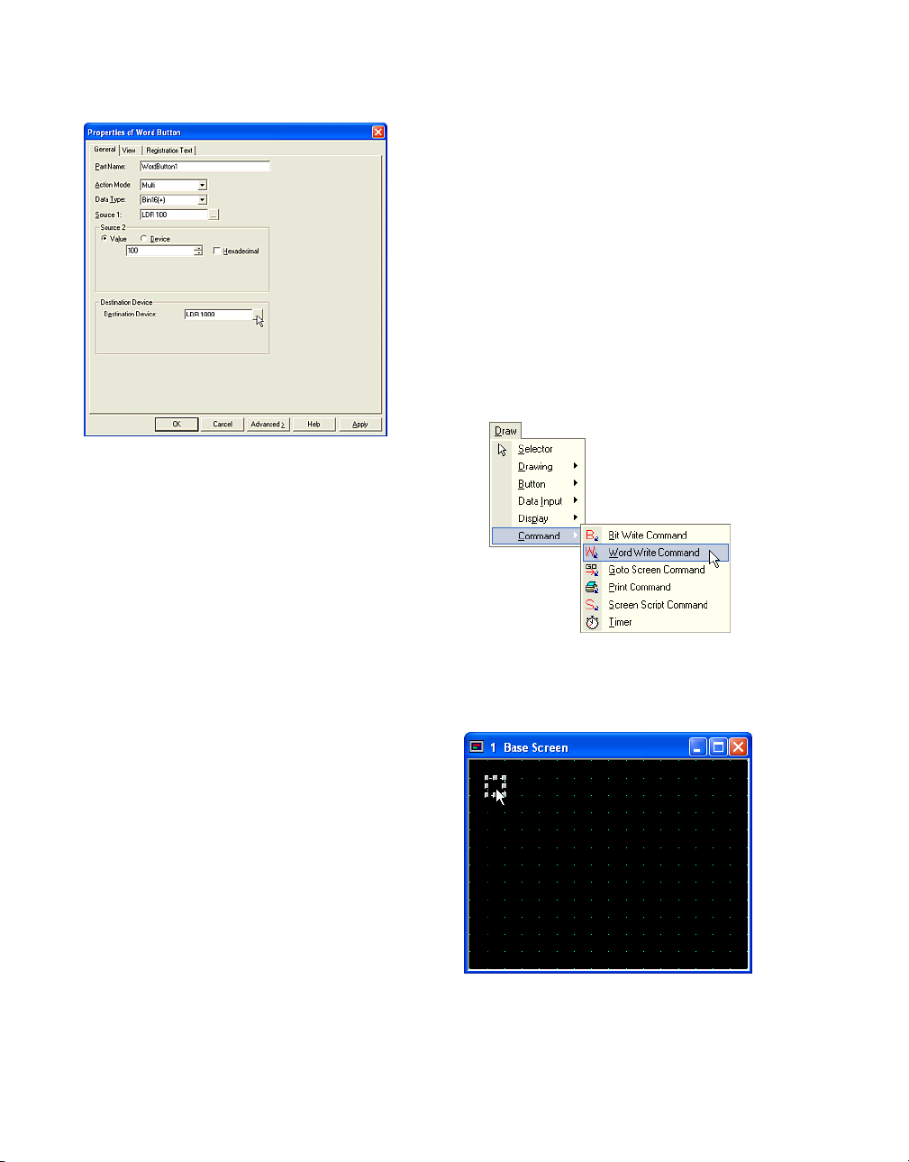
How to Use an Object
Set a word device to [Destination Device] box.
In this case, enter "LDR 1000".
Click [OK].
2.3.8 Writing a Calculation to a Word Device with a Command
Tutorial: You will create a specific trigger condition that when satisfied will calculate the value
of the selected word device and write the result
to the specified device. For example, while the
result, which adds the value of the HG Internal
Register (LDR 10) and the value of LDR 20, is
less than the value of the HG Internal Register
(LDR 10), the result which performs a logical
AND between the value of LDR 1000 and LDR
2000 is written to LDR 100. The numerical formulas are "LDR 10 + LDR 20 > 1000" and "LDR
1000 & LDR 2000 = LDR 100".
2-42
Click the [Word Write Command] button on the
toolbar (or select [Draw] [Command] [Word
Write Command] from the menu).
Double-click the selected object after placing
on the screen. The properties dialog box will
appear.
Page 91

Writing a Calculation to a Word Device with a Command
Select an [Action Mode]. In this case, select
"AND" because the specified devices are performed a logical AND when the specified trigger
conditions are established.
Select a [Data Type]. This setting should be
selected according to the values of [Source1],
[Source 2] or [Destination Device]. In this case,
select "Bin16(+)".
Set a word device in the [Source 1] box. In this
case, select (or type) "LDR 1000".
Select a type and set a word device in the
[Source2] box. In this case, select "Device" and
enter "LDR 2000".
2-43
Page 92
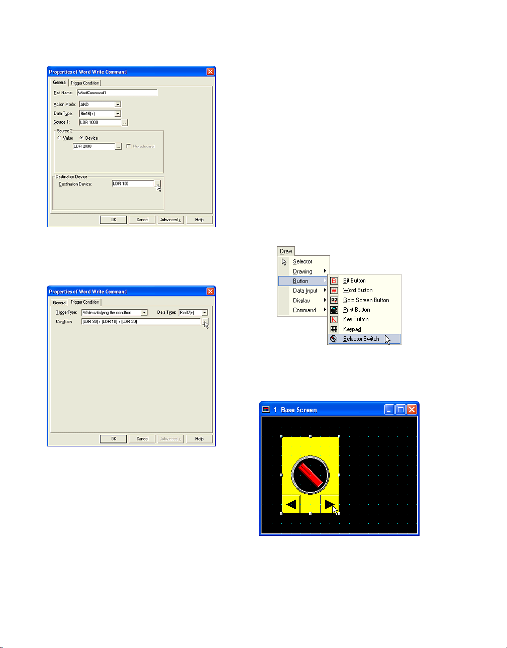
How to Use an Object
Set a word device in the [Destination Device]
box. In this case, enter "LDR 100".
Click [Trigger Condition] tab.
2.3.9 Switching a Bit with a Selector Switch
Tutorial: When you press the button of the
Selector Switch, one of the specified bit devices
or word devices with bit turns from 0 to 1 and
the others turn to 0. You will create a Selector
Switch that has 3 channels, the registration text
will be dark blue and read "Ch1", "Ch2" and
"Ch3". The default state of the knob is center,
"HG Internal Relay (LM 1)" is 1 and the others
are 0. When you press the left button of Selector Switch and the knob leans to the left, "LM 0"
turns to 1 and the others turn to 0. When you
press the right button and the knob slants to the
right, "LM 2" turns to 1 and the others turn to 0.
Set the Trigger Condition. For more information
see “Setting a Trigger Condition” - “Executing
the Command According to the State of the
Device” on page 2-28. In this case, select
"While satisfy the condition" in [Trigger Type],
"Bin32(+)" as the [Data Type] and enter "[LDR
30] > [LDR 10] + [LDR 20]" in [Condition].
If you enter a conditional expression in the
[Condition] box directly, you have to put the
device in square brackets as shown above.
Click [OK].
2-44
Click the [Selector Switch] button on the toolbar
(or select [Draw] [Button] [Selector Switch] from
the menu).
Double-click the selected object after placing
on the screen. The properties dialog box will
appear.
Page 93
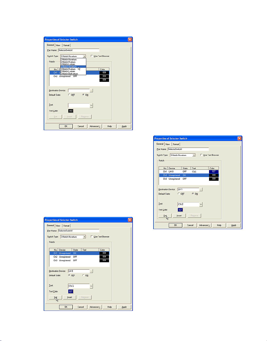
Select a [Switch Type]. This setting changes
the number of the channels in the [Notch] box.
In this case, select "3-Notch No-return".
If you want to use already registered text as the
registration text of the channel, check this box.
(The Text ID settings will appear in the Notch.
Enter the ID number of the registered text or
click the […] button to select from the Text
Browser. Select the desired selection and click
[Select]. The Text Browser will close and the
selected Text ID and corresponding text from
the Text ID will appear in the Text box.)
Switching a Bit with a Selector Switch
Set a bit device or a word device with bit in the
[Destination Device] box. In this case, enter
"LM 0".
Select the [Default State]. This setting is available when the HG starts running. In this case,
select "OFF".
Enter text in the [Text] box. In this case, enter
"Ch1".
Click [Text Color]. The Color Palette dialog box
will appear. In this case, select "027".
Click [Set].
The settings will appear on the list and the
focus moves to Ch2 automatically.
Set a bit device or a word device with bit in the
[Destination Device] box. In this case, enter
"LM 1".
Select the [Default State]. In this case, "ON" is
already selected because one of channels is
always set to "ON" automatically.
Enter text in the [Text] box. In this case, enter
"Ch2".
Click [Text Color]. The Color Palette dialog box
will appear. In this case, select "027".
2-45
Page 94
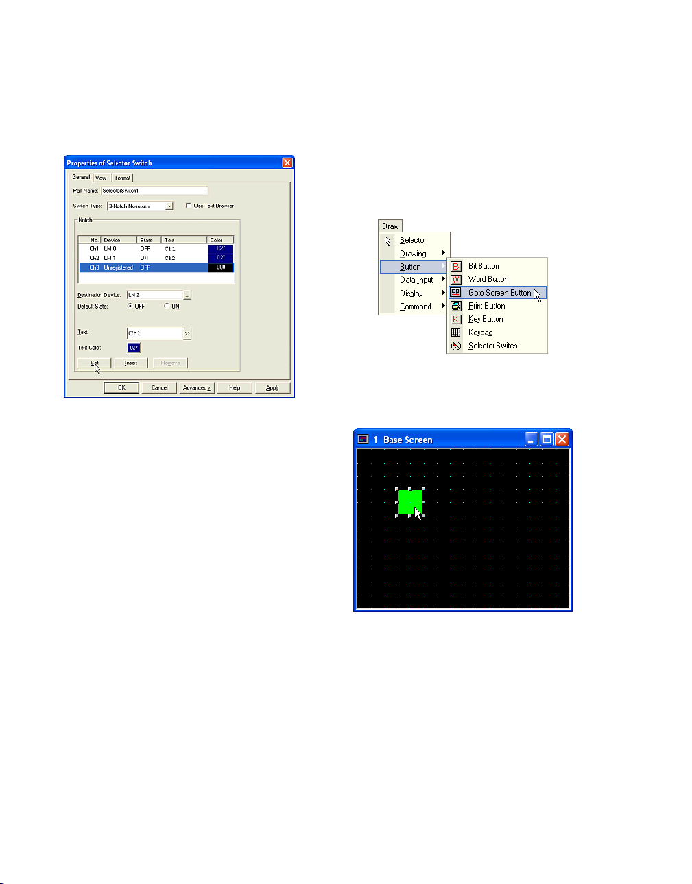
How to Use an Object
Click [Set].
The settings will appear on the list and the
focus moves to Ch3 automatically.
Set a bit device or a word device with bit to the
[Destination Device] box. In this case, enter
"LM 2".
Select the [Default] State]. In this case, "OFF" is
already selected.
2.4 Changing Screens
2.4.1 Changing Screens with a Button
Tutorial: When you push the button on Base
Screen 1,the HG switches from Base Screen 1
to Base Screen 2.
Click the [Goto Screen Button] button on the
toolbar (or select [Draw] [Button] [Goto Screen
Button] from the menu).
Enter text in the [Text] box. In this case, enter
"Ch3".
Click [Text Color]. The Color Palette dialog box
will appear. In this case, select "027".
Click [Set].
The settings will appear on the list.
Click [OK].
2-46
Double-click the selected object after placing
on the screen. The properties dialog box will
appear.
Page 95
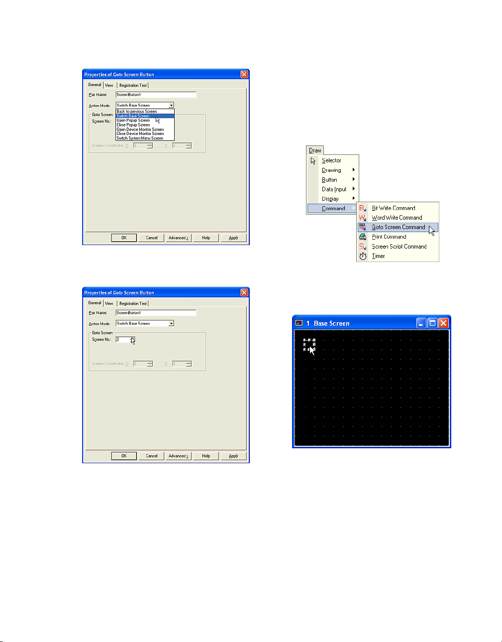
Select an [Action Mode]. In this case, select
"Switch Base Screen".
Using a Condition to Change the Screen
2.4.2 Using a Condition to Change the Screen
Tutorial: When the selected device "HG Internal
Relay (LM 0)" turns from 0 to 1, the displayed
screen changes from Base Screen 1 to Base
Screen 2.
Click the [Goto Screen Command] button on
the toolbar (or select [Draw] [Command] [Goto
Screen Command] from the menu).
Enter a number in the [Screen No.] box. In this
case, enter "2".
Click [OK].
Double-click the selected object after placing
on the screen. The properties dialog box will
appear.
2-47
Page 96
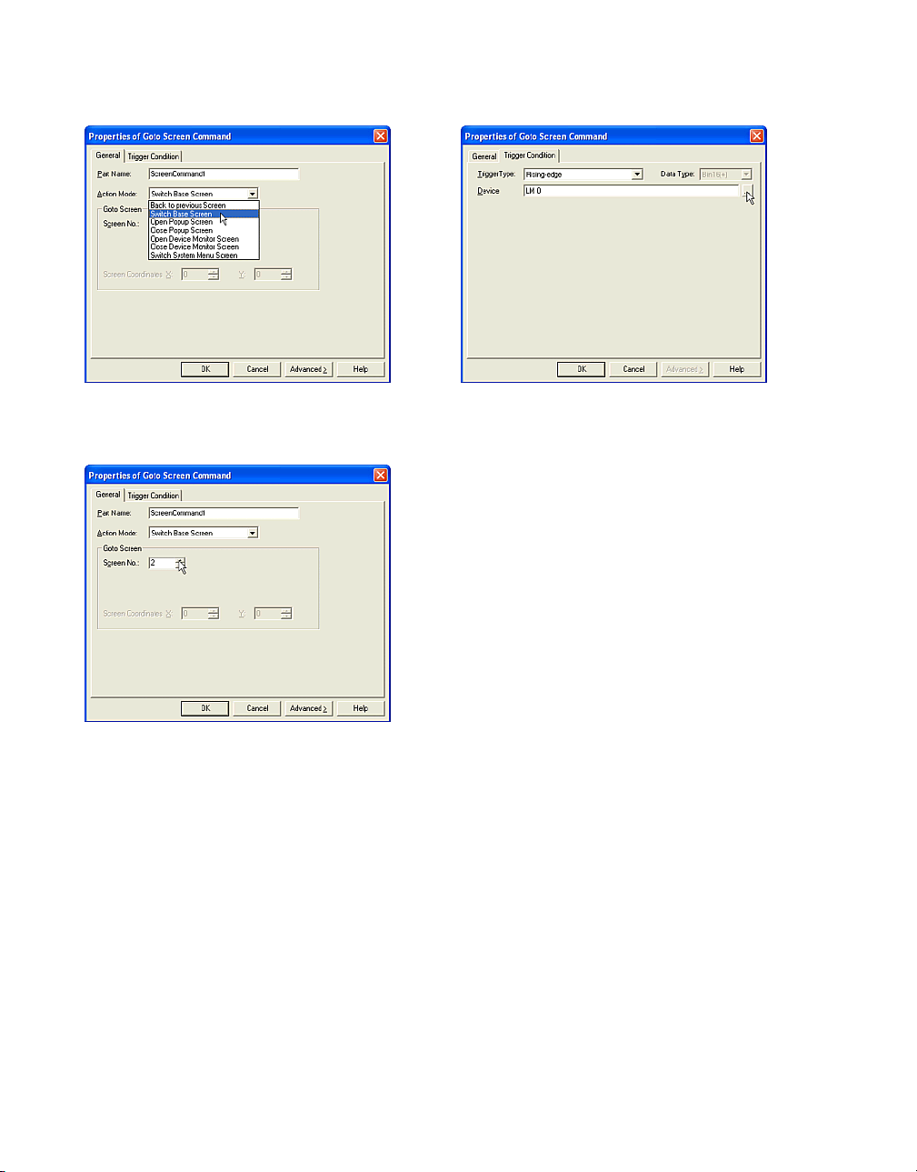
How to Use an Object
Select an [Action Mode]. In this case, select
"Switch Base Screen".
Enter a number in the [Screen No.]. In this
case, enter "2".
Click [Trigger Condition] tab.
Set the Trigger Condition. For more information
see “Setting a Trigger Condition” - “Executing
the Command According to the State of the
Device” on page 2-28. In this case, select "Ris-
ing-edge" in [Trigger Type] and enter "LM 0" as
the [Device].
Click [OK].
2-48
Page 97

2.5 Using a Popup Screen
2.5.1 Opening a Popup Screen
With a Button
Tutorial: You will create a button on Base
Screen 1. When you press the button Popup
Screen 1000 will appear at (100, 40).
Opening a Popup Screen With a Button
Click the [Goto Screen Button] button on the
toolbar (or select [Draw] [Button] [Goto Screen
Button] from the menu).
Double-click the selected object after placing
on the screen. The properties dialog box will
appear.
Select an [Action Mode]. In this case, select
"Open Popup Screen".
Enter a number for the popup screen in the
[Screen No.] box. In this case, enter "1000".
2-49
Page 98

How to Use an Object
Enter coordinates for the location of the upper
left corner of the popup screen in the [X] and [Y]
boxes. In this case, enter "(100, 40)".
Click [OK].
Double-click the selected object after placing
on the screen. The properties dialog box will
appear.
2.5.2 Opening a Popup Screen with a Command
Tutorial: When the HG Internal Relay (LM 0)
turns from 0 to 1, Popup Screen 1000 will
appear at (100, 40).
Click the [Goto Screen Command] button on
the toolbar (or select [Draw] [Command] [Goto
Screen Command] from the menu).
2-50
Select an [Action Mode]. In this case, select
"Open Popup Screen".
Page 99

Closing a Popup Screen with a Button
Enter a number for the popup screen in the
[Screen No.] box. In this case, enter "1000".
Enter coordinates for the upper left corner of
the popup screen in the [X] and [Y] boxes. In
this case, enter "(100, 40)".
Click [Trigger Condition] tab.
2.5.3 Closing a Popup Screen with a Button
Tutorial: You will create a button on Base
Screen 1. When you press the button, the
Popup Screen 1000 will close.
Click the [Goto Screen Button] button on the
toolbar (or select [Draw] [Button] [Goto Screen
Button] from the menu).
Set the Trigger Condition. For more information
see “Setting a Trigger Condition” - “Executing
the Command According to the State of the
Device” on page 2-28.In this case, select "Ris-
ing-edge" in [Trigger Type] and enter "LM 0" as
the [Device].
Click [OK].
Double-click the selected object after placing
on the screen. The properties dialog box will
appear.
2-51
Page 100

How to Use an Object
2.5.4 Closing a Popup Screen with a Command
Tutorial: When the HG Internal Relay (LM 0)
turns from 1 to 0, Popup Screen 1000 will close.
Select an [Action Mode]. In this case, select
"Close Popup Screen".
Enter a number for the popup screen in the
[Screen No.] box. In this case, enter "1000".
Click [OK].
Click the [Goto Screen Command] button on
the toolbar (or select [Draw] [Command] [Goto
Screen Command] from the menu).
Double-click the selected object after placing
on the screen. The properties dialog box will
appear.
2-52
 Loading...