


M
ICROSMART
This document describes communication commands for the MicroSmart micro programmable controller.
C
OMMUNICATION
P
ROTOCOL
Table of Contents
Communication Command List . . . . . . . . . . . . . . . . . . . . . . . . . . . . . . . . . . . . . . . . 1
Communication Procedure . . . . . . . . . . . . . . . . . . . . . . . . . . . . . . . . . . . . . . . . . . . . 2
Message Format . . . . . . . . . . . . . . . . . . . . . . . . . . . . . . . . . . . . . . . . . . . . . . . . . . . 2
Request Messages . . . . . . . . . . . . . . . . . . . . . . . . . . . . . . . . . . . . . . . . . . . . . . . . . 3
Receive Timeout . . . . . . . . . . . . . . . . . . . . . . . . . . . . . . . . . . . . . . . . . . . . . . . . . . . 4
Reply Messages . . . . . . . . . . . . . . . . . . . . . . . . . . . . . . . . . . . . . . . . . . . . . . . . . . . 5
Write User Program in ASCII Format . . . . . . . . . . . . . . . . . . . . . . . . . . . . . . . . . . . . 7
Write User Program in Binary Format . . . . . . . . . . . . . . . . . . . . . . . . . . . . . . . . . . . . 9
Read User Program in ASCII Format . . . . . . . . . . . . . . . . . . . . . . . . . . . . . . . . . . . . 11
Read User Program in Binary Format . . . . . . . . . . . . . . . . . . . . . . . . . . . . . . . . . . . 13
Write N Bytes . . . . . . . . . . . . . . . . . . . . . . . . . . . . . . . . . . . . . . . . . . . . . . . . . . . . 15
Read N Bytes . . . . . . . . . . . . . . . . . . . . . . . . . . . . . . . . . . . . . . . . . . . . . . . . . . . . 18
Write 1 Bit . . . . . . . . . . . . . . . . . . . . . . . . . . . . . . . . . . . . . . . . . . . . . . . . . . . . . . 21
Read 1 Bit . . . . . . . . . . . . . . . . . . . . . . . . . . . . . . . . . . . . . . . . . . . . . . . . . . . . . . 23
Read Error Code . . . . . . . . . . . . . . . . . . . . . . . . . . . . . . . . . . . . . . . . . . . . . . . . . . 25
Clear Operand Data . . . . . . . . . . . . . . . . . . . . . . . . . . . . . . . . . . . . . . . . . . . . . . . . 29
Enable/Disable User Program Protection . . . . . . . . . . . . . . . . . . . . . . . . . . . . . . . . 31
Read PLC Operating Status . . . . . . . . . . . . . . . . . . . . . . . . . . . . . . . . . . . . . . . . . . 33
Read Scan Time . . . . . . . . . . . . . . . . . . . . . . . . . . . . . . . . . . . . . . . . . . . . . . . . . . 34
Read PLC System Program Version . . . . . . . . . . . . . . . . . . . . . . . . . . . . . . . . . . . . 35
Read Timer Information . . . . . . . . . . . . . . . . . . . . . . . . . . . . . . . . . . . . . . . . . . . . . 36
Read Counter Information . . . . . . . . . . . . . . . . . . . . . . . . . . . . . . . . . . . . . . . . . . . 38
Read Timer Preset Value Change Status . . . . . . . . . . . . . . . . . . . . . . . . . . . . . . . . 40
Read Counter Preset Value Change Status . . . . . . . . . . . . . . . . . . . . . . . . . . . . . . . 42
Read Timeout Status . . . . . . . . . . . . . . . . . . . . . . . . . . . . . . . . . . . . . . . . . . . . . . . 44
Read Countout Status . . . . . . . . . . . . . . . . . . . . . . . . . . . . . . . . . . . . . . . . . . . . . . 45
Confirm Changed Timer/Counter Preset Values . . . . . . . . . . . . . . . . . . . . . . . . . . . 46
NG Code and Action . . . . . . . . . . . . . . . . . . . . . . . . . . . . . . . . . . . . . . . . . . . . . . . 47
Operand Allocation Numbers . . . . . . . . . . . . . . . . . . . . . . . . . . . . . . . . . . . . . . . . . 48
Index . . . . . . . . . . . . . . . . . . . . . . . . . . . . . . . . . . . . . . . . . . . . . . . . . . . . . . . . . . 49
www.idec.com
X
X
X
X
X
X
X
X
M
ICROSMART COMMUNICATION PROTOCOL
Communication Command List
All communication commands available for the
MicroSmart, OpenNet Controller (ONC)
,
MICRO
3
, and
rized in the table below. Some of the commands are the same as for different PLCs, with increased operands and operand
number ranges.
MICRO
3
C
are summa-
Command Name MicroSmart ONC MICRO
Write User Program in ASCII Format
Write User Program in Binary Format
Read User Program in ASCII Format
Read User Program in Binary Format
Write N Bytes
3
C MICRO
XXXX
XXXX
XXXX
XXXX
XXXX
3
Read N Bytes (Note) XXXX
Write 1 Bit
Read 1 Bit
Read High-speed Counter Preset and Current Values
Read Error Code
Clear Operand Data
Enable/Disable User Program Protection
Read PLC Operating Status
Read Scan Time
Read PLC System Program Version
Read User Communication Transmit/Receive Buffer
XXXX
XXXX
XXX
XXXX
XXXX
XXXX
XXXX
XXXX
XXXX
XX
Clear and Start User Communication Data Monitor
Read User Communication Status
XX
Read Communication Mode
Select Word Operands for Monitor
Monitor Selected Word Operands
Read Timer Information
Read Counter Information
Read Timer Preset Value Change Status
Read Counter Preset Value Change Status
XX
XX
XX
XX
Read FUN Area Settings
Read Random Words
Read Timeout Status
Read Countout Status
Confirm Changed Timer/Counter Preset Values
X
Note: When timer/counter preset or current values are read out from the MicroSmart using the read N bytes command, the
result is different from that read from the MICRO
3
because the MicroSmart has different timer and counter internal codes to
enable 16-bit timers and counters. The MicroSmart has new commands for timers and counters; Read Timeout Status and
Read Countout Status.
ICROSMART
M
1
M
ICRO
S
MART
C
OMMUNICATION
P
ROTOCOL
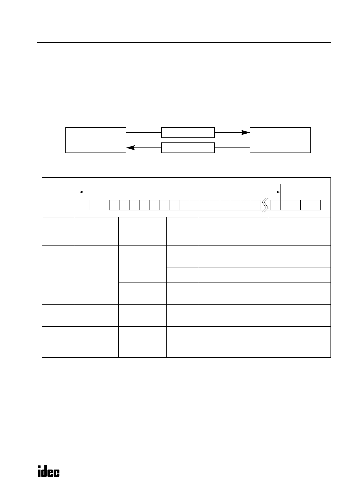
Communication Procedure
The computer and the
which consist of request messages and reply messages. The request message is sent from the computer to write data to,
read or clear data from the
from the computer.
Communication is always initiated by the computer by sending a request message to the
reply message to the computer. The
can initiate communication using the user communication function.
Smart
MicroSmart
Computer
CPU module communicate data by sending and receiving communication messages,
MicroSmart
MicroSmart
. The reply message is sent from the
cannot initiate communication in the computer link system. The
Request Message
Reply Message
MicroSmart
in response to the request message
MicroSmart
, which then returns a
MicroSmart
CPU Module
Micro-
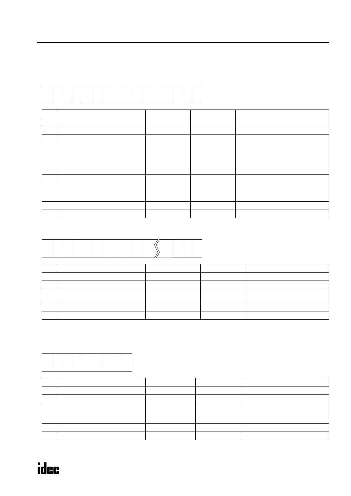
Message Format
Communication
Message
(1) (2) (3) (4) (5)
BCC (Block Check Character) Calculation Range
(1)
(2)
(3)
(4)
(5)
Communication
control
character
(1 byte)
Communication
device number
(2 bytes)
Data
(variable length)
BCC
(2 bytes)
Terminator
(1 byte)
Message start
character
Device number to
send request to
Device number to
send reply from
Communication
command,
data type, etc.
Block check
character
Message
end code
ENQ (05h) Enquiry Request message
ACK (06h)
NAK (15h)
00 (0)
through
1F (31)
FF (255)
00 (0)
through
1F (31)
Depends on each command.
See “Request Messages” on page 3.
See “Reply Messages” on page 5.
Exclusive OR (XOR) of the BCC calculation range.
CR (0Dh) Default
Acknowledge
Negative acknowledge
Designates a PLC device number to which the computer sends a request message in the 1:N communication computer link system.
Used in the 1:1 communication computer link system.
PLC of any device number receives request message.
Indicates the device number of the PLC which returns
the reply message.
Reply message
M
ICRO
S
MART
2
M
ICRO
S
MART
C
OMMUNICATION
P
ROTOCOL
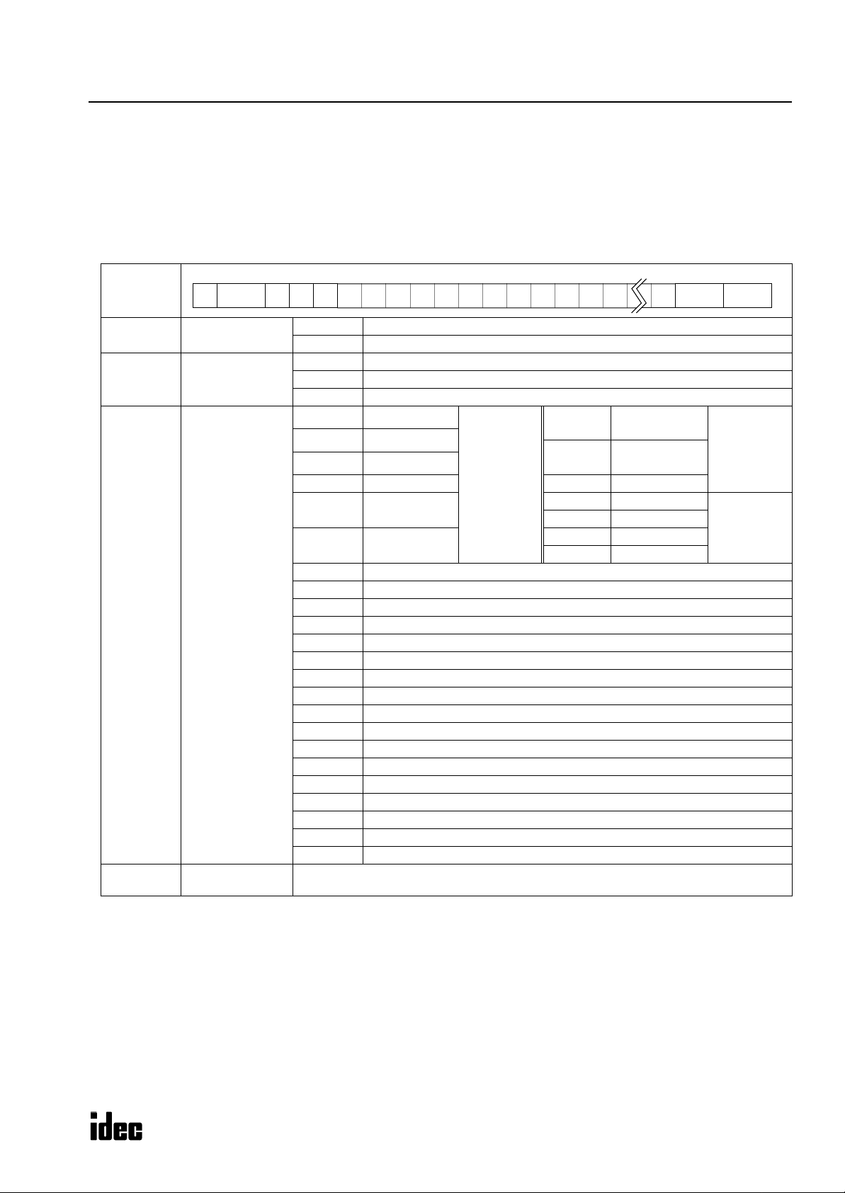
Request Messages
ONC
Like the
MICRO
or
structures.
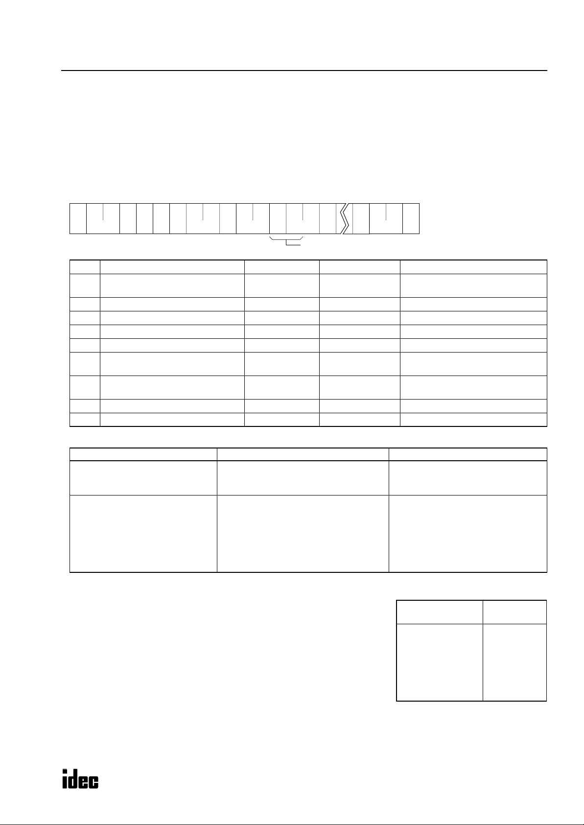
Request Message 1
Request message 1 is a command message to be sent from the computer to the PLC, containing a command. The data type
code included in the request message determines the function. The data structure of request message 1 is shown below.
Request
Message 1
(1)
(2)
(3)
(4)
Continuation
(1 byte)
Command
(1 byte)
Data type
(1 byte)
Data
(variable length)
3
, request messages are available in request message 1 and request message 2 with different data
ENQ
Device (2) (4)(3)05h (1) BCC
0 (30h) Discontinued (no message follows)
1 (31h) Continued (another message follows)
W (57h) Write data to PLC
R (52h) Read data from PLC
C (43h) Clear data from PLC
X (58h)
Y (59h) Output
M (4Dh) Internal relay
R (52h) Shift register D (44h) Data register
T (54h)
C (43h)
E (45h) Error code (read/clear)
I (49h) Link formatting sequence (clear)
K (4Bh) Scan time (read)
N (4Eh) PLC system program version (read)
P (50h) User program in ASCII format (read/write)
Q (51h) Changed timer/counter preset values (write)
S (53h) PLC operating status (read)
V (56h) User program protection
W (57h) Calendar/clock (read/write)
Z (5Ah) System reset (clear)
_ (5Fh) Timer information (read)
` (60h) Counter information (read)
a (61h) Timer preset value change status (read)
b (62h) Counter preset value change status (read)
d (64h) Timer timeout status (read)
e (65h) Counter countout status (read)
p (70h) User program in binary format (read/write)
Data (depends on command and data type)
Input
Timer
(preset value)
Counter
(preset value)
N-byte
designation
t (74h)
c (63h)
x (78h) Input
y (79h) Output
m (6Dh) Internal relay
r (72h) Shift register
Timer
(current value)
Counter
(current value)
Termi-
nator
N-byte
designation
1-bit
designation
(1)
“Continued” is used in request message 1 for writing the user program to inform the PLC that another request message
will be sent successively. In all other request messages, “discontinued” is used. When “continued” is specified, the
computer sends a request message, receives a reply message, and sends another request message.
(2)
The command code is available in three types; write data, read data, and clear data.
(3)
The data type code selects an operand or function. Upper- and lower-case characters have different functions.
The data specifies the operand number, the quantity of bytes of the data for reading or writing, etc. depending on the
(4)
command and data type.
ICRO
MART
M
S
3
M
ICRO
S
MART
C
OMMUNICATION
P
ROTOCOL
Request Message 2
Request message 2 is a command message used for writing and reading user programs. The data structure of request message 2 is shown below:
Request
Message 2
(1)
(2)
(1)
“Discontinued” is used for both writing and reading user programs to inform the PLC that no request message will be
sent successively.
(2)
The data length is variable for writing user programs and is 1-byte long (“R”) for reading user programs.
ENQ
Device (2)05h (1) BCC
Continuation
(1 byte)
Data
(variable length)
Data
(1 byte)
0 (30h) Discontinued (no message follows)
User program (write user program)
R (52h) Read user program
Termi-
nator
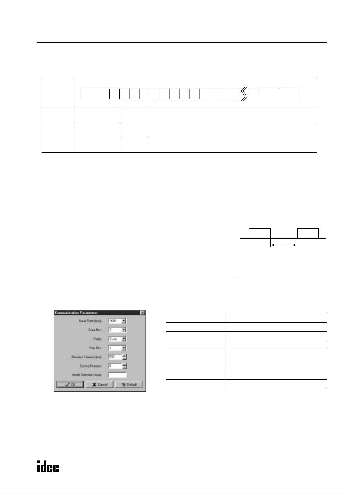
Receive Timeout
When a request message contains an interval of 500 msec or more between onebyte character data and the next one-byte character data, the PLC understands that
the communication is canceled and does not return a reply message.
When the interval is 500 msec or more, extend the receive timeout value using
WindLDR
. The receive timeout can be selected between 10 and 2540 msec in 10msec increments. To enable the optional communication mode, turn on the mode
selection input designated on the Communication Parameters page in
T o access the Communication P arameters page from the
WindLDR
WindLDR
.
menu bar, select Configure > Function Area Settings .
In the Function Area Setting dialog box, click the Communication tab, and select Maintenance Protocol in the Port 1 or
2 pull-down list.
Click the Configure button. The Communication Parameters dialog box appears. Change settings, if required.
Baud Rate (bps) 1200, 2400, 4800, 9600, 19200
Data Bits 7 or 8
Parity None, Odd, Even
Stop Bits 1 or 2
10 to 2540 (10-msec increments)
Receive Timeout (ms)
Device Number 0 to 31
Mode Selection Input Any input number
(Receive timeout is disabled when 2550
is selected.)
Data Data
≤ 500 msec
Note: Only when the mode selection input is turned on, the selected communication parameters are enabled.
Otherwise, default communication parameters take effect; 9600 bps, 7 data bits, even parity, 1 stop bit,
receive timeout 500 msec.
For details, see the MicroSmart User’s Manual EM342, page 25-2.
ICRO
MART
M
S
4
M
ICROSMART COMMUNICATION PROTOCOL
Reply Messages
Reply messages are available in ACK reply message and NAK reply message with different data structures.
ACK Reply Message
The ACK reply message is a reply or response to the request message and is sent from the PLC to the computer when communication is completed normally.
ACK
Reply
Message
(1)
(2)
ACK
Device (2)06h (1) BCC
0 (30h) OK: Discontinued All communication is completed normally (end of processing).
Communication in reply to request is completed normally and
another reply message follows when reading a user program.
Communication device number, command, data type, data, or continuation code is not within the range supported by the PLC or
does not match its status. When this error occurs, communication
is halted without regard to the continuation code.
The data length depends on the request
command (variable length).
Command
(1 byte)
1 (31h) OK: Continued
2 (32h) NG: Error
OK
reply
When request command is W or C No data exists. (0 byte)
When request command is R
NG code (2 bytes)
Data
(variable
length)
0 (30h)
to
9 (39h)
or
A (41h)
to
F (46h)
NG
reply
NG
Code
Program size error Improper write/read program size
01
Protect error Protected against write/read in the PLC
02
RUN error Writing user program is attempted while the PLC
03
CRC error User program CRC code does not match
04
Protect code error Protect code in the request message does not
05
Data range error Invalid data range designated
06
Timer/counter preset
07
value change error
Calendar/clock data error Invalid value written to calendar/clock
08
Data clear error Designated data cannot be cleared
09
Data error Invalid data other than 0 (30h) - 9 (39h) or
10
Setting error Incorrect setting for user communication
11
CPU module type code
12
error
Error Cause
is running
match that set in the PLC. Attempt was made to
enable protection on a protected user program.
Preset value change is attempted to timer or
counter with preset value designated by data register
A (41h) - F (46h)
CPU module type code in the request message
does not match the connected PLC.
Termi-
nator
(1)
The command code indicates whether the request command is completed normally or not and also whether another
reply message will be sent successively.
When reading a user program from the PLC, reply message 1 is returned in response to request message 1 and reply
message 2 is returned in response to request message 2. Reply message 1 contains command 1 (OK: continued) to
inform the computer that another reply message follows. All other reply messages contain command 0 (OK: discontinued) to indicate that no reply message follows when communication is completed normally.
When an OK reply is returned in response to request command R (read data), the read data is included in this place.
(2)
When an NG reply is returned, the cause of error exists in the PLC. See page 47.
ICROSMART
M
5

M
ICROSMART COMMUNICATION PROTOCOL
NAK Reply Message
When an error is found during communication, a NAK reply message is sent from the PLC to the computer.
NAK
Reply
Message
NAK
Device15h (1) (2) BCC
Termi-
nator
(1) Command 0 (no meaning): dummy data for consistent communication format
Depending on the communication error, an error code is set in this place.
(2)
Communication
error code
(2 bytes)
Error
Code
00
01
02
03
04
BCC error Appended BCC code does not match BCC calculated
Frame error Quantity of received bits differs from the preset
Data send/receive error Parity error or overrun error occurred.
Command error Unsupported request message is received.
Procedure/data quantity error Received request message does not match the
Error Type Error Contents
value of received data.
value (stop bit is 0 for example).
expected data (including quantity of data).
(1) The command code in the NAK reply message is always 0.
(2) The next two bytes indicate the communication error code.
M
ICROSMART
6
M
ICROSMART COMMUNICATION PROTOCOL
Write User Program in ASCII Format
The user program can be written from a computer to the PLC. When transferring a user program through modem, this
command is recommended to transfer the user program in ASCII format because modems understand ASCII codes.
When writing a user program from a computer, two request messages must be sent to the PLC.
Send request message 1 first. After confirming that the returned reply message is an OK reply, send request message 2.
Request Messages (Write User Program in ASCII Format)
Request Message 1
**05h
** 57h
(1) (2)
(1)
(2)
(3)
(4)
(5)
(6)
(7)
(8)
(9)
(3)
Communication control character 1 byte ENQ (05h) Enquiry
Communication device number 2 bytes
Continuation 1 byte 1 (31h) Continued
Command 1 byte W (57h) Write data
Data type 1 byte P (50h) User program in ASCII format
CPU module type code 1 byte
Program capacity 8 bytes
BCC 2 bytes 00 - 7F Block check character
Terminator 1 byte CR (0Dh) Message end code
(4)
50h
(5)
3*h
(6)
** ** **
** **
** ** ** **
(7)
00 - 1F
FF
0 (30h)
1 (31h)
2 (32h)
3 (33h)
4 (34h)
6 (36h)
0000 0000
:
FFFF FFFF
(8)
**31h
0Dh
(9)
Device number 0 through 31
Device number 255 (all devices)
10-I/O
16-I/O
20-I/O transistor output
24-I/O
40-I/O
20-I/O relay output
User program includes data of rung
comments and tag comments plus
function area settings. The function
area occupies 94 bytes.
Request Message 2
**05h
** ** ** ** ** **30h
(1) (2)
(1)
(2)
(3)
(4)
(5)
(6)
Note: The user program must be stored in a file of the ASCII code format. Ladder program files (.LDR) cannot be sent to the
PLC using this request message.
(3)
Communication control character 1 byte ENQ (05h) Enquiry
Communication device number 2 bytes
Continuation 1 byte 0 (30h) Discontinued
User program
BCC 2 bytes 00 - 7F Block check character
Terminator 1 byte CR (0Dh) Message end code
** ** ** **
(4)
Variable length
64,336 bytes max.
(5)
**
0Dh
(6)
00 - 1F
FF
0 (30h) - 9 (39h)
A (41h) - F (46h)
Device number 0 through 31
Device number 255 (all devices)
User program (ASCII code file)
M
ICROSMART
7

Reply Messages (Write User Program in ASCII Format)
OK Reply (Reply to Request Messages 1 and 2)
**06h
** **
(1) (2)
(1)
(2)
(3)
(4)
(5)
(3)
Communication control character 1 byte ACK (06h) Acknowledge
Communication device number 2 bytes 00 - 1F Device number 0 through 31
Command 1 byte 0 (30h) OK: Discontinued
BCC 2 bytes 00 - 7F Block check character
Terminator 1 byte CR (0Dh) Message end code
NG Reply (Reply to Request Message 1)
**06h
** 30h
32h
(1) (2)
(1)
(2)
(3)
(4)
(5)
(6)
(3)
Communication control character 1 byte ACK (06h) Acknowledge
Communication device number 2 bytes 00 - 1F Device number 0 through 31
Command 1 byte 2 (32h) NG
NG code 2 bytes
BCC 2 bytes 00 - 7F Block check character
Terminator 1 byte CR (0Dh) Message end code
(4)
(4)
**30h
0Dh
(5)
**
**3*h 0Dh
(5)
(6)
M
ICROSMART COMMUNICATION PROTOCOL
01 (30h 31h)
02 (30h 32h)
03 (30h 33h)
04 (30h 34h)
12 (31h 32h)
Program capacity error
Protect error
RUN error
CRC error
CPU module type code error
Note: NG reply never occurs in response to reply message 2.
M
ICROSMART
8

M
ICROSMART COMMUNICATION PROTOCOL
Write User Program in Binary Format
The user program can be written from a computer to the PLC. This command can send a user program faster than the
Write User Program in ASCII format command.
When writing a user program from a computer, two request messages must be sent to the PLC.
Send request message 1 first. After confirming that the returned reply message is an OK reply, send request message 2.
Request Messages (Write User Program in Binary Format)
Request Message 1
**05h
** 57h
31h
(1) (2)
(1)
(2)
(3)
(4)
(5)
(6)
(7)
(8)
(9)
(3)
Communication control character 1 byte ENQ (05h) Enquiry
Communication device number 2 bytes
Continuation 1 byte 1 (31h) Continued
Command 1 byte W (57h) Write data
Data type 1 byte p (70h) User program in binary format
CPU module type code 1 byte
Program capacity 8 bytes
BCC 2 bytes 00 - 7F Block check character
Terminator 1 byte CR (0Dh) Message end code
(4)
70h
(5)
3*h
(6)
** ** **
** **
** ** ** **
(7)
00 - 1F
FF
0 (30h)
1 (31h)
2 (32h)
3 (33h)
4 (34h)
6 (36h)
0000 0000
:
FFFF FFFF
** 0Dh
(8)
(9)
Device number 0 through 31
Device number 255 (all devices)
10-I/O
16-I/O
20-I/O transistor output
24-I/O
40-I/O
20-I/O relay output
User program includes data of rung
comments and tag comments plus
function area settings. The function
area occupies 94 bytes.
Request Message 2
**05h
** ** ** ** ** **30h
(1) (2)
(1)
(2)
(3)
(4)
(5)
(6)
Note: The user program must be stored in a file of the binary code format. Ladder program files (.LDR) cannot be sent to the
PLC using this request message.
(3)
Communication control character 1 byte ENQ (05h) Enquiry
Communication device number 2 bytes
Continuation 1 byte 0 (30h) Discontinued
User program
BCC 2 bytes 00 - FF Block check character
Terminator 1 byte CR (0Dh) Message end code
** ** ** **
(4)
Variable length
32,168 bytes max.
(5)
**
0Dh
(6)
00 - 1F
FF
(00h) - (FFh) User program (binary code file)
Device number 0 through 31
Device number 255 (all devices)
M
ICROSMART
9
Reply Messages (Write User Program in Binary Format)
OK Reply (Reply to Request Messages 1 and 2)
**06h
** **
(1) (2)
(1)
(2)
(3)
(4)
(5)
(3)
Communication control character 1 byte ACK (06h) Acknowledge
Communication device number 2 bytes 00 - 1F Device number 0 through 31
Command 1 byte 0 (30h) OK: Discontinued
BCC 2 bytes 00 - 7F Block check character
Terminator 1 byte CR (0Dh) Message end code
NG Reply (Reply to Request Message 1)
**06h
** 30h
32h
(1) (2)
(1)
(2)
(3)
(4)
(5)
(6)
(3)
Communication control character 1 byte ACK (06h) Acknowledge
Communication device number 2 bytes 00 - 1F Device number 0 through 31
Command 1 byte 2 (32h) NG
NG code 2 bytes
BCC 2 bytes 00 - 7F Block check character
Terminator 1 byte CR (0Dh) Message end code
(4)
(4)
**30h
0Dh
(5)
**
**3*h 0Dh
(5)
(6)
M
ICROSMART COMMUNICATION PROTOCOL
01 (30h 31h)
02 (30h 32h)
03 (30h 33h)
04 (30h 34h)
12 (31h 32h)
Program capacity error
Protect error
RUN error
CRC error
CPU module type code error
Note: NG reply never occurs in response to reply message 2.
M
ICROSMART
10

M
ICROSMART COMMUNICATION PROTOCOL
Read User Program in ASCII Format
The user program can be read from the PLC to a computer.
When reading a user program to a computer, two request messages must be sent from the computer to the PLC.
Send request message 1 first. After confirming that the returned reply message is an OK reply, send request message 2.
Specify a value larger than the user program capacity selected in the PLC in place of the program capacity in request mes-
sage 1. Reserve a buffer in the computer to store the data of the specified program capacity temporarily.
Request Messages (Read User Program in ASCII Format)
Request Message 1
**05h
** 52h
31h
(1) (2)
(1)
(2)
(3)
(4)
(5)
(6)
(7)
(8)
(9)
(3)
Communication control character 1 byte ENQ (05h) Enquiry
Communication device number 2 bytes
Continuation 1 byte 1 (31h) Continued
Command 1 byte R (52h) Read data
Data type 1 byte P (50h) User program in ASCII format
CPU module type code 1 byte
Program capacity 8 bytes
BCC 2 bytes 00 - 7F Block check character
Terminator 1 byte CR (0Dh) Message end code
(4)
50h
(5)
3*h
(6)
** ** **
** **
** ** ** **
(7)
00 - 1F
FF
0 (30h)
1 (31h)
2 (32h)
3 (33h)
4 (34h)
6 (36h)
0000 0000
:
FFFF FFFF
** 0Dh
(8)
(9)
Device number 0 through 31
Device number 255 (all devices)
10-I/O
16-I/O
20-I/O transistor output
24-I/O
40-I/O
20-I/O relay output
User program includes data of rung
comments and tag comments plus
function area settings. The function
area occupies 94 bytes.
Request Message 2
**05h
** 30h
(1) (2)
(1)
(2)
(3)
(4)
(5)
(6)
(3)
(4)
Communication control character 1 byte ENQ (05h) Enquiry
Communication device number 2 bytes
Continuation 1 byte 0 (30h) Discontinued
Command 1 byte R (52h) Read data
BCC 2 bytes 00 - 7F Block check character
Terminator 1 byte CR (0Dh) Message end code
**
**52h
0Dh
(5)
(6)
M
ICROSMART
00 - 1F
FF
Device number 0 through 31
Device number 255 (all devices)
11

Reply Messages (Read User Program in ASCII Format)
OK Reply
• Reply Message 1
**06h
** 31h
(1) (2)
(1)
(2)
(3)
(4)
(5)
(6)
(7)
(3)
Communication control character 1 byte ACK (06h) Acknowledge
Communication device number 2 bytes 00 - 1F Device number 0 through 31
Command 1 byte 1 (31h) OK: Continued
CPU module type code 1 byte
Program capacity 8 bytes
BCC 2 bytes 00 - 7F Block check character
Terminator 1 byte CR (0Dh) Message end code
3*h
(4)
** ** **
** **
** ** ** **
(5)
** 0Dh
(6)
M
ICROSMART COMMUNICATION PROTOCOL
(7)
0 (30h)
1 (31h)
2 (32h)
3 (33h)
4 (34h)
6 (36h)
0000 0000
:
FFFF FFFF
10-I/O
16-I/O
20-I/O transistor output
24-I/O
40-I/O
20-I/O relay output
User program includes data of rung
comments and tag comments plus
function area settings. The function
area occupies 94 bytes.
• Reply Message 2
**06h
** ** ** ** ** **30h
(1) (2)
(1)
(2)
(3)
(4)
(5)
(6)
(3)
Communication control character 1 byte ACK (06h) Acknowledge
Communication device number 2 bytes 00 - 1F Device number 0 through 31
Command 1 byte 0 (30h) OK: Discontinued
User program
BCC 2 bytes 00 - 7F Block check character
Terminator 1 byte CR (0Dh) Message end code
** ** ** **
(4)
Variable length
64,336 bytes max.
(5)
**
0Dh
(6)
0 (30h) - 9 (39h)
A (41h) - F (46h)
Note: The received user program is stored on the disk in the ASCII code format.
NG Reply (Reply to Request Message 1)
**06h
** 30h
32h
(1) (2)
(1)
(2)
(3)
(4)
(5)
(6)
(3)
Communication control character 1 byte ACK (06h) Acknowledge
Communication device number 2 bytes 00 - 1F Device number 0 through 31
Command 1 byte 2 (32h) NG
NG code 2 bytes
BCC 2 bytes 00 - 7F Block check character
Terminator 1 byte CR (0Dh) Message end code
(4)
**
**3*h 0Dh
(5)
(6)
01 (30h 31h)
02 (30h 32h)
04 (30h 34h)
User program (ASCII code file)
Program capacity error
Protect error
CRC error
Note: NG reply never occurs in response to reply message 2.
M
ICROSMART
12
M
ICROSMART COMMUNICATION PROTOCOL
Read User Program in Binary Format
The user program can be read from the PLC to a computer.
When reading a user program to a computer, two request messages must be sent from the computer to the PLC.
Send request message 1 first. After confirming that the returned reply message is an OK reply, send request message 2.
Specify a value larger than the user program capacity selected in the PLC in place of the program capacity in request mes-
sage 1. Reserve a buffer in the computer to store the data of the specified program capacity temporarily.
Request Messages (Read User Program in Binary Format)
Request Message 1
** 52h
31h
(1) (2)
Communication control character 1 byte ENQ (05h) Enquiry
(1)
Communication device number 2 bytes
(2)
Continuation 1 byte 1 (31h) Continued
(3)
Command 1 byte R (52h) Read data
(4)
Data type 1 byte p (70h) User program in binary format
(5)
CPU module type code 1 byte
(6)
Program capacity 8 bytes
(7)
BCC 2 bytes 00 - 7F Block check character
(8)
Terminator 1 byte CR (0Dh) Message end code
(9)
(3)
(4)
Request Message 2
70h
(5)
3*h
(6)
** ** **
** **
** ** ** ****05h
(7)
00 - 1F
FF
0 (30h)
1 (31h)
2 (32h)
3 (33h)
4 (34h)
6 (36h)
0000 0000
:
FFFF FFFF
** 0Dh
(8)
(9)
Device number 0 through 31
Device number 255 (all devices)
10-I/O
16-I/O
20-I/O transistor output
24-I/O
40-I/O
20-I/O relay output
User program includes data of rung
comments and tag comments plus
function area settings. The function
area occupies 94 bytes.
**05h
** 30h
(1) (2)
(1)
(2)
(3)
(4)
(5)
(6)
(3)
Communication control character 1 byte ENQ (05h) Enquiry
Communication device number 2 bytes
Continuation 1 byte 0 (30h) Discontinued
Command 1 byte R (52h) Read data
BCC 2 bytes 00 - 7F Block check character
Terminator 1 byte CR (0Dh) Message end code
(4)
**
**52h
0Dh
(5)
(6)
M
ICROSMART
00 - 1F
FF
Device number 0 through 31
Device number 255 (all devices)
13
Reply Messages (Read User Program in Binary Format)
OK Reply
• Reply Message 1
**06h
** 31h
(1) (2)
(1)
(2)
(3)
(4)
(5)
(6)
(7)
(3)
Communication control character 1 byte ACK (06h) Acknowledge
Communication device number 2 bytes 00 - 1F Device number 0 through 31
Command 1 byte 1 (31h) OK: Continued
CPU module type code 1 byte
Program capacity 8 bytes
BCC 2 bytes 00 - 7F Block check character
Terminator 1 byte CR (0Dh) Message end code
3*h
(4)
** ** **
** **
** ** ** **
(5)
** 0Dh
(6)
M
ICROSMART COMMUNICATION PROTOCOL
(7)
0 (30h)
1 (31h)
2 (32h)
3 (33h)
4 (34h)
6 (36h)
0000 0000
:
FFFF FFFF
10-I/O
16-I/O
20-I/O transistor output
24-I/O
40-I/O
20-I/O relay output
User program includes data of rung
comments and tag comments plus
function area settings. The function
area occupies 94 bytes.
• Reply Message 2
**06h
** ** ** ** ** **30h
(1) (2)
(1)
(2)
(3)
(4)
(5)
(6)
(3)
Communication control character 1 byte ACK (06h) Acknowledge
Communication device number 2 bytes 00 - 1F Device number 0 through 31
Command 1 byte 0 (30h) OK: Discontinued
User program
BCC 2 bytes 00 - FF Block check character
Terminator 1 byte CR (0Dh) Message end code
** ** ** **
(4)
Variable length
32,168 bytes max.
(5)
**
0Dh
(6)
(00h) - (FFh) User program (binary code file)
Note: The received user program is stored on the disk in the binary code format.
NG Reply (Reply to Request Message 1)
**06h
** 30h
32h
(1) (2)
(1)
(2)
(3)
(4)
(5)
(6)
(3)
Communication control character 1 byte ACK (06h) Acknowledge
Communication device number 2 bytes 00 - 1F Device number 0 through 31
Command 1 byte 2 (32h) NG
NG code 2 bytes
BCC 2 bytes 00 - 7F Block check character
Terminator 1 byte CR (0Dh) Message end code
(4)
**
**3*h 0Dh
(5)
(6)
01 (30h 31h)
02 (30h 32h)
04 (30h 34h)
Program capacity error
Protect error
CRC error
Note: NG reply never occurs in response to reply message 2.
M
ICROSMART
14
M
Calendar/clock
operand number
Data
0000
0001
0002
0003
0004
0005
0006
Year
Month
Day
Day of week
Hour
Minute
Second
ICROSMART COMMUNICATION PROTOCOL
Write N Bytes
Data can be written into N-bytes of operands starting with the specified operand number in the PLC.
This command can be used to turn on or off bit operands such as inputs, outputs, internal relays, and shift register bits in
units of 8 bits.
This command can also be used to change timer and counter preset values, enter data into data registers, and set calendar/
clock data.
Request Message (Write N Bytes)
**05h
(1) (2)
(1)
(2)
(3)
(4)
(5)
(6)
(7)
(8)
(9)
(10)
** ** **30h
Communication control character 1 byte ENQ (05h) Enquiry
Communication device number 2 bytes
Continuation 1 byte 0 (30h) Discontinued
Command 1 byte W (57h) Write data
Data type 1 byte See table below. N-byte designation
Operand number 4 bytes See table below. First operand number to write to
Data length (n) 2 bytes 00 - C8
Data
BCC 2 bytes 00 - 7F Block check character
Terminator 1 byte CR (0Dh) Message end code
(3)
57h
(4)
(5)
** ** **
(6)
****
**
**
(7)
2n bytes
1 ≤ n ≤ 200
** ** ** **
(8)
Data for 1-byte operand after ASCII conversion
00 - 1F
FF
0 (30h) - 9 (39h)
A (41h) - F (46h)
**
0Dh
(9)
(10)
Device number 0 through 31
Device number 255 (all devices)
Byte count of data to write
200 (C8h) bytes maximum
Data to write
X (58h)
Y (59h)
M (4Dh)
R (52h)
T (54h)
t (74h)
C (43h)
c (63h)
D (44h)
W (57h)
Note: The valid operand range depends on the CPU module type. For details, see page 48.
Operand numbers for calendar and clock are allocated as listed on the right:
When the range specified by the data type and data length is invalid, the PLC
returns an NG reply.
When a data register is designated as a preset value for a timer or counter, data
cannot be written into the preset value. To change the preset value, write data
into the data register designated as a preset value.
(5) Data type code (6) Operand number (Note) Remarks
Input
Output
Internal relay
Shift register
Timer (preset value)
Timer (current value)
Counter (preset value)
Counter (current value)
Data register
Calendar/clock
0000 - 0307
0000 - 0307
0000 - 1277, 8000 - 8077
0000 - 0127
0000 - 0099
0000 - 0099
0000 - 0099
0000 - 0099
0000 - 1299, 2000 - 7999, 8000 - 8199
0000 - 0006
M
ICROSMART
The least significant digit of the operand number is an octal number (0-7).
Upper digits are decimal numbers.
All four digits of the operand number
are decimal numbers.
15

Reply Messages (Write N Bytes)
OK Reply
**06h
(1) (2)
Communication control character 1 byte ACK (06h) Acknowledge
(1)
Communication device number 2 bytes 00 - 1F Device number 0 through 31
(2)
Command 1 byte 0 (30h) OK: Discontinued
(3)
BCC 2 bytes 00 - 7F Block check character
(4)
Terminator 1 byte CR (0Dh) Message end code
(5)
NG Reply
**06h
(1) (2)
Communication control character 1 byte ACK (06h) Acknowledge
(1)
Communication device number 2 bytes 00 - 1F Device number 0 through 31
(2)
Command 1 byte 2 (32h) NG
(3)
NG code 2 bytes
(4)
BCC 2 bytes 00 - 7F Block check character
(5)
Terminator 1 byte CR (0Dh) Message end code
(6)
** **
(3)
** 30h
32h
(3)
(4)
(4)
**30h
0Dh
(5)
**
**3*h 0Dh
(5)
(6)
M
ICROSMART COMMUNICATION PROTOCOL
06 (30h 36h)
07 (30h 37h)
08 (30h 38h)
Data range error
Timer/counter preset value change error
Calendar/clock data error
Data Format in the Request Message (Write N Bytes)
X (Input), Y (Output), M (Internal Relay), and R (Shift Register)
To write ON/OFF statuses of bit operands such as inputs, outputs, internal relays, or shift registers, divide the operand
numbers into 8-bit (1-byte) groups, and convert the 8-bit value into a hexadecimal value. Then, convert the hexadecimal
value into ASCII codes. Include the ASCII codes in place of “Data” in the request message.
Example: To write data to outputs Q0 through Q17 to set Q5, Q7, Q12, and Q15 and reset other outputs.
Q7 Q0
1 0 1 0 0 0 0 0
A0h
In this example, convert the hexadecimal value A024 into ASCII codes, and include the results (41h 30h 32h 34h) in the
request message. Consequently, the data to send has a length of 4 bytes in the request message.
The data length to write in this example is 16 bits, or 2 (02h) bytes, of output points. So, include ASCII codes 30h 32h in
place of “Data length” in the request message.
Q17 Q10
0 0 1 0 0 1 0 0
24h
M
ICROSMART
16

M
ICROSMART COMMUNICATION PROTOCOL
T (Timer Preset Value) and C (Counter Preset Value)
To write data into word operands such as timers and counters, convert the hexadecimal values into ASCII codes. Include
the ASCII codes in place of “Data” in the request message.
Example: To write decimal 987 and 36000 to preset values for timers T0 and T1, respectively.
T0
0987
T1
36000
In this example, conv ert the decimal v alues into hexadecimal values and send
data 03DB8CA0 (30h 33h 44h 42h 38h 43h 41h 30h).
03DBh 8CA0h
The data length of this example is 2 words, or 4 (04h) bytes. So, include ASCII codes 30h 34h in place of “Data length” in
the request message.
Since the MicroSmart uses separate memory areas for timers and counters, timer and counter preset values are written into
the specified operand number in different memory areas.
D (Data Register)
To write data into word operands of data registers, convert the hexadecimal values into ASCII codes. Include the ASCII
codes in place of “Data” in the request message.
Example: To write 123Bh and 4567h to data registers D0 and D1, respectively.
D0
123Bh
D1
4567h
In this example, send data 123B4567 (31h 32h 33h 42h 34h 35h 36h 37h).
The data length of this example is 2 words, or 4 (04h) bytes. So, include ASCII codes 30h 34h in place of “Data length” in
the request message.
W (Calendar/Clock)
T o send calendar/clock operands such as year, month, day , day of week, hour, minute, and second, write each one-word (2
bytes) data directly.
Day of week data format (0 through 6) is assigned as follows:
012 3 456
Sunday Monday Tuesday Wednesday Thursday Friday Saturday
Example: To send calendar/clock data Monday, January 1, 2001, 13 hour, 24 minutes, 56 seconds.
Year
01
0001 0001
Month
January
Day
1
0001
Day of week
Monday
0001
Hour
13
0013
Minute
24
0024
Second
56
0056
In this example, send data 0001000100010001001300240056 (30h 30h 30h 31h 30h 30h 30h 31h 30h 30h 30h 31h 30h
30h 30h 31h 30h 30h 31h 33h 30h 30h 32h 34h 30h 30h 35h 36h).
The data length of this example is 7 words, or 14 (0Eh) bytes. So, include ASCII codes 30h 3Eh in place of “Data length”
in the request message.
M
ICROSMART
17

M
ICROSMART COMMUNICATION PROTOCOL
Read N Bytes
Data can be read from N-bytes of operands starting with the specified operand number in the PLC.
This command can be used to monitor the ON/OFF statuses of bit operands such as inputs, outputs, internal relays, and
shift register bits in units of 8 bits.
This command can also be used to monitor preset and current values of timers and counters, data of data registers, and read
calendar/clock data.
Request Message (Read N Bytes)
**05h
** 30h
(1) (2)
(1)
(2)
(3)
(4)
(5)
(6)
(7)
(8)
(9)
(3)
(4)
Communication control character 1 byte ENQ (05h) Enquiry
Communication device number 2 bytes
Continuation 1 byte 0 (30h) Discontinued
Command 1 byte R (52h) Read data
Data type 1 byte See table below. N-byte designation
Operand number 4 bytes See table below. First operand number to read
Data length (n) 2 bytes 00 - C8
BCC 2 bytes 00 - 7F Block check character
Terminator 1 byte CR (0Dh) Message end code
(5)
** ** **
(6)
****
**
**
** 0Dh
(7)
**52h
(8)
(9)
00 - 1F
FF
Device number 0 through 31
Device number 255 (all devices)
Byte count of data to read
200 (C8h) bytes maximum
(5) Data type code (6) Operand number (Note) Remarks
X (58h)
Y (59h)
M (4Dh)
R (52h)
T (54h)
t (74h)
C (43h)
c (63h)
D (44h)
W (57h)
Note: The valid operand range depends on the CPU module type. For details, see page 48.
Input
Output
Internal relay
Shift register
Timer (preset value)
Timer (current value)
Counter (preset value)
Counter (current value)
Data register
Calendar/clock
0000 - 0307
0000 - 0307
0000 - 1277, 8000 - 8157
0000 - 0127
0000 - 0099
0000 - 0099
0000 - 0099
0000 - 0099
0000 - 1299, 2000 - 7999, 8000 - 8199
0000 - 0006
The least significant digit of the operand number is an octal number (0-7).
Upper digits are decimal numbers.
All four digits of the operand number
are decimal numbers.
Operand numbers for calendar and clock are allocated as listed on the right:
operand number
The internal relay memory area is divided into the ordinary internal relays and
special internal relays. N-byte data cannot be read from the internal relay area
continuing from the ordinary internal relays through special internal relays.
When the range specified by the data type and data length is invalid, the PLC
returns an NG reply.
When a preset value is read from a timer or counter for which a data register is
designated as a preset value, the preset value is returned as a reply, rather than
the data register number.
Calendar/clock
0000
0001
0002
0003
0004
0005
0006
Data
Year
Month
Day
Day of week
Hour
Minute
Second
M
ICROSMART
18

Reply Messages (Read N Bytes)
OK Reply
**06h
(1) (2)
Communication control character 1 byte ACK (06h) Acknowledge
(1)
Communication device number 2 bytes 00 - 1F Device number 0 through 31
(2)
Command 1 byte 0 (30h) OK: Discontinued
(3)
Data
(4)
BCC 2 bytes 00 - 7F Block check character
(5)
Terminator 1 byte CR (0Dh) Message end code
(6)
NG Reply
**06h
(1) (2)
** ** **30h
** 30h
** ** ** **
(3)
32h
(4)
(3)
Data for 1-byte operand in ASCII format
**
**3*h 0Dh
(5)
(6)
** ** ** **
(4)
2n bytes
1 ≤ n ≤ 200
M
ICROSMART COMMUNICATION PROTOCOL
**
0Dh
(5)
(6)
0 (30h) - 9 (39h)
A (41h) - F (46h)
Read data
Communication control character 1 byte ACK (06h) Acknowledge
(1)
Communication device number 2 bytes 00 - 1F Device number 0 through 31
(2)
Command 1 byte 2 (32h) NG
(3)
NG code 2 bytes
(4)
BCC 2 bytes 00 - 7F Block check character
(5)
Terminator 1 byte CR (0Dh) Message end code
(6)
06 (30h 36h)
08 (30h 38h)
Data range error
Calendar/clock data error
Data Format in the Reply Message (Read N Bytes)
X (Input), Y (Output), M (Internal Relay), and R (Shift Register)
When reading ON/OFF statuses of bit operands such as inputs, outputs, internal relays, or shift registers, the received data
shows the hexadecimal value of 8-bit groups.
Example: The read data is 02C4 (30h 32h 43h 34h) when reading 2 bytes starting with internal relay M0.
02h
0 0 0 0 0 0 1 0
M7 M0
1 1 0 0 0 1 0 0
M17 M10
Divide the read data into one-byte (8-bit) groups. The bits where a 1 is stored are ON. In this example, internal relays M1,
M12, M16, and M17 are on.
C4h
M
ICROSMART
19

M
ICROSMART COMMUNICATION PROTOCOL
T (Timer Preset Value), t (Timer Current Value), C (Counter Preset Value), and c (Counter Current Value)
The Read N Bytes command can be used to read preset or current values of consecutive timers or counters. When reading
timer/counter preset or current values, the received data show the hexadecimal values in four characters each.
Example: The read data is EA602710 (45h 41h 36h 30h 32h 37h 31h 30h) when reading 4 bytes of timer current values
starting with timer T10.
Divide the received data into 4-character groups and convert the data into 4-
EA60h 2710h
digit hexadecimal values. In this example, the read data is shown below:
T10 = EA60h (60000 decimal)
T10 T11
T11 = 2710h (10000 decimal)
To read preset, current values, and timer status of timers, use the Read Timer Information command (see page 36).
To read preset, current values, and counter status of counter, use the Read Counter Information command (see page 38).
D (Data Register)
When reading data registers, the received data show the hexadecimal values in four characters each.
Example: The read data is C7380100 (43h 37h 33h 38h 30h 31h 30h 30h) when reading 4 bytes starting with data register
D27.
Divide the received data into 4-character groups and convert the data into 4-
C738h 0100h
digit hexadecimal values. In this example, the read data is shown below:
D27 = C738h (51000 decimal)
D27 D28
D28 = 100h (256 decimal)
W (Calendar/Clock)
Calendar/clock data are received in units of 2 bytes starting with the specified operand number 0000 (year) through 0006
(second). For operand numbers for the calendar and clock, see page 18.
Day of week data format (0 through 6) is assigned as follows:
012 3 456
Sunday Monday Tuesday Wednesday Thursday Friday Saturday
Example: The read data is 000200200059 (30h 30h 30h 32h 30h 30h 32h 30h 30h 30h 35h 39h) when reading 6 bytes (3
words) starting with operand number 0003 (day of week) for reading calendar/clock values.
Divide the received data into 4-character groups and convert
the data into 4-digit hexadecimal values.
0002h
0020h 0059h
Data of three operands starting with 0003 (day of week) is
read as shown on the right.
2 = Tuesday
20 hours 59 minutes
M
ICROSMART
20

M
ICROSMART COMMUNICATION PROTOCOL
Write 1 Bit
Data can be written into 1 bit of the specified operand in the PLC, enabling to set (ON) or reset (OFF) the operand.
The PLC operation can be started or stopped by setting or resetting start control special internal relay M8000 using this
request message.
Request Message (Write 1 Bit)
**05h
** 30h
(1) (2)
(1)
(2)
(3)
(4)
(5)
(6)
(7)
(8)
(9)
(3)
(4)
Communication control character 1 byte ENQ (05h) Enquiry
Communication device number 2 bytes
Continuation 1 byte 0 (30h) Discontinued
Command 1 byte W (57h) Write data
Data type 1 byte See table below. 1-bit designation
Operand number 4 bytes See table below. Operand number to write to
ON/OFF status 1 byte
BCC 2 bytes 00 - 7F Block check character
Terminator 1 byte CR (0Dh) Message end code
(5)
** ** **
(6)
****
3*h
(7)
**
**57h
0Dh
(8)
(9)
00 - 1F
FF
0 (30h)
1 (31h)
Device number 0 through 31
Device number 255 (all devices)
OFF
ON
(5) Data type code (6) Operand number (Note) Remarks
x (78h)
y (79h)
m (6Dh)
r (72h) Shift register 0000 - 0127
Note: The valid operand range depends on the CPU module type. For details, see page 48.
Input
Output
Internal relay
0000 - 0307
0000 - 0307
0000 - 1277, 8000 - 8077
The least significant digit of the operand number is an octal number (0-7).
Upper digits are decimal numbers.
All four digits of the operand number
are decimal numbers.
M
ICROSMART
21

Reply Messages (Write 1 Bit)
OK Reply
**06h
(1) (2)
Communication control character 1 byte ACK (06h) Acknowledge
(1)
Communication device number 2 bytes 00 - 1F Device number 0 through 31
(2)
Command 1 byte 0 (30h) OK: Discontinued
(3)
BCC 2 bytes 00 - 7F Block check character
(4)
Terminator 1 byte CR (0Dh) Message end code
(5)
NG Reply
**06h
(1) (2)
Communication control character 1 byte ACK (06h) Acknowledge
(1)
Communication device number 2 bytes 00 - 1F Device number 0 through 31
(2)
Command 1 byte 2 (32h) NG
(3)
NG code 2 bytes 06 (30h 36h) Data range error
(4)
BCC 2 bytes 00 - 7F Block check character
(5)
Terminator 1 byte CR (0Dh) Message end code
(6)
** **
(3)
** 30h
32h
(3)
(4)
(4)
**30h
0Dh
(5)
**
**36h 0Dh
(5)
(6)
M
ICROSMART COMMUNICATION PROTOCOL
M
ICROSMART
22

M
ICROSMART COMMUNICATION PROTOCOL
Read 1 Bit
Data can be read from 1 bit of the specified operand in the PLC to see if the operand is on or off.
The read 1 bit command can be used to monitor the ON/OFF status of a bit operand such as input, output, internal relay, or
shift register bit.
Request Message (Read 1 Bit)
**05h
** 30h
(1) (2)
(1)
(2)
(3)
(4)
(5)
(6)
(7)
(8)
(3)
(4)
Communication control character 1 byte ENQ (05h) Enquiry
Communication device number 2 bytes
Continuation 1 byte 0 (30h) Discontinued
Command 1 byte R (52h) Read data
Data type 1 byte See table below. 1-bit designation
Operand number 4 bytes See table below. Operand number to read from
BCC 2 bytes 00 - 7F Block check character
Terminator 1 byte CR (0Dh) Message end code
(5)
** ** **
(6)
**
(7)
**52h
0Dh
(8)
00 - 1F
FF
Device number 0 through 31
Device number 255 (all devices)
****
(5) Data type code (6) Operand number (Note) Remarks
x (78h)
y (79h)
m (6Dh)
r (72h) Shift register 0000 - 0127
Note: The valid operand range depends on the CPU module type. For details, see page 48.
Input
Output
Internal relay
0000 - 0307
0000 - 0307
0000 - 1277, 8000 - 8157
The least significant digit of the operand number is an octal number (0-7).
Upper digits are decimal numbers.
All four digits of the operand number
are decimal numbers.
M
ICROSMART
23

Reply Messages (Read 1 Bit)
OK Reply
**06h
(1) (2)
Communication control character 1 byte ACK (06h) Acknowledge
(1)
Communication device number 2 bytes 00 - 1F Device number 0 through 31
(2)
Command 1 byte 0 (30h) OK: Discontinued
(3)
ON/OFF status 1 byte
(4)
BCC 2 bytes 00 - 7F Block check character
(5)
Terminator 1 byte CR (0Dh) Message end code
(6)
NG Reply
**06h
(1) (2)
Communication control character 1 byte ACK (06h) Acknowledge
(1)
Communication device number 2 bytes 00 - 1F Device number 0 through 31
(2)
Command 1 byte 2 (32h) NG
(3)
NG code 2 bytes 06 (30h 36h) Data range error
(4)
BCC 2 bytes 00 - 7F Block check character
(5)
Terminator 1 byte CR (0Dh) Message end code
(6)
** **
** 30h
(3)
32h
(3)
3*h
(4)
(4)
(5)
**30h
**
0Dh
(6)
**36h 0Dh
(5)
(6)
M
ICROSMART COMMUNICATION PROTOCOL
0 (30h)
1 (31h)
OFF
ON
M
ICROSMART
24

Read Error Code
Error codes can be read from the PLC.
Request Message (Read Error Code)
**05h
** 30h
(1) (2)
(1)
(2)
(3)
(4)
(5)
(6)
(7)
(8)
(9)
(3)
(4)
Communication control character 1 byte ENQ (05h) Enquiry
Communication device number 2 bytes
Continuation 1 byte 0 (30h) Discontinued
Command 1 byte R (52h) Read data
Data type 1 byte E (45h) Error code
Error address 4 bytes See table below. First error address to read
Data length (n) 2 bytes 02 - 0C
BCC 2 bytes 00 - 7F Block check character
Terminator 1 byte CR (0Dh) Message end code
30h 30h 30h
(5)
3*h45h
(6)
30h
(7)
M
ICROSMART COMMUNICATION PROTOCOL
**52h
**
** 0Dh
(8)
(9)
00 - 1F
FF
Device number 0 through 31
Device number 255 (all devices)
2 bytes per error address
12 (0Ch) bytes maximum
(6) Error address Error details
0000 General error code
0001 User program syntax error: Type code
0002 User program syntax error: Address code
0003 Advanced instruction syntax error
0004 User program execution error
0005 Link communication error
M
ICROSMART
25

Reply Messages (Read Error Code)
OK Reply
**06h
(1) (2)
Communication control character 1 byte ACK (06h) Acknowledge
(1)
Communication device number 2 bytes 00 - 1F Device number 0 through 31
(2)
Command 1 byte 0 (30h) OK: Discontinued
(3)
Data
(4)
BCC 2 bytes 00 - 7F Block check character
(5)
Terminator 1 byte CR (0Dh) Message end code
(6)
NG Reply
**06h
(1) (2)
** ** **30h
** 30h
** ** ** **
(3)
32h
(4)
(3)
(4)
Error code for the first error address to read
**
**36h 0Dh
(5)
(6)
** ** ** **
4n bytes
(1 ≤ n ≤ 6)
M
ICROSMART COMMUNICATION PROTOCOL
**
0Dh
(5)
(6)
0 (30h) - 9 (39h)
A (41h) - F (46h)
Error code
(4 bytes per error address)
Communication control character 1 byte ACK (06h) Acknowledge
(1)
Communication device number 2 bytes 00 - 1F Device number 0 through 31
(2)
Command 1 byte 2 (32h) NG
(3)
NG code 2 bytes 06 (30h 36h) Data range error (error address)
(4)
BCC 2 bytes 00 - 7F Block check character
(5)
Terminator 1 byte CR (0Dh) Message end code
(6)
Data Format in the Reply Message (Read Error Code)
When reading error codes, the received data show the hexadecimal values in four characters each.
Example: The read data is 0080 0000 0000 0000 0000 0000 when reading 12 (0Ch) bytes starting with error address
0000.
Divide the received data into 4-character groups and convert the data into 4-digit hexadecimal values.
Error address: 0000
0080h
In this example, the read data is shown below:
0000 General error code 80h
0001 User program syntax error: Type code 0h
0002 User program syntax error: Address code 0h
0003 Advanced instruction syntax error code 0h
0004 User program execution error code 0h
0005 Data link communication error code 0h
0001
0000h
0002
0000h
0003
0000h
0004
0000h
0005
0000h
The above data means that user program syntax error (error code 80h) is found.
Since user program syntax errors and advanced instruction syntax errors never occur, the reply message contains 0 at error
addresses 0001 through 0003.
For details of error codes, see the next page.
M
ICROSMART
26

Error Codes
General Error Code
Error Code Bit Position Error Status
1h bit 0 Power failure
2h bit 1 Watch dog timer error
4h bit 2 Data link connection error
8h bit 3 User program EEPROM sum check error
10h bit 4 Timer/counter preset value sum check error
20h bit 5 User program RAM sum check error
40h bit 6 Keep data error
80h bit 7 User program syntax error
100h bit 8 User program writing error
200h bit 9 CPU module error
400h bit 10 Clock IC error
800h bit 11 Unused
1000h bit 12 Unused
2000h bit 13 I/O bus initialize error
4000h bit 14 Unused
8000h bit 15 Unused
M
ICROSMART COMMUNICATION PROTOCOL
User Program Execution Error Code — Special internal relay M8004 goes on
This error indicates that invalid data is found during execution of a user program. When this error occurs, special internal
relay M8004 (user program execution error) is also turned on. The detailed information of this error can be viewed at this
error address. When this error occurs, program operation and all output statuses are maintained.
User Program
Execution Error Code
(D8006)
1 Source/destination operand is out of range
2 MUL result is out of data type range.
3 DIV result is out of data type range, or division by 0.
4 BCDLS has S1 or S1+1 exceeding 9999.
5 HTOB(W) has S1 exceeding 9999.
6 BTOH has any digit of S1 exceeding 9.
7 HTOA/ATOH/BTOA/ATOB has quantity of digits to convert out of range.
8 ATOH/ATOB has non-ASCII data for S1 through S1+4.
9
10
11 DGRD data exceeds 65535 with BCD5 digits selected.
12 CVXTY/CVYTX is executed without matching XYFS.
13 CVXTY/CVYTX has S2 exceeding the value specified in XYFS.
14 Label in LJMP/LCAL is not found.
WKTIM has S1, S2, and S3 exceeding the valid range.
S1: 0 through 127
S2/S3: Hour data 0 through 23, minute data 0 through 59
S2/S3 can be 10000.
WKTBL has S1 through Sn out of range.
Month: 01 through 12
Day: 01 through 31
Error Details
M
ICROSMART
27

User Program
Execution Error Code
(D8006)
15 TXD/RXD is executed while the RS232C port 1 or 2 is
16 PID instruction execution error.
17
18
19 Attempt was made to execute an instruction that is not available for the PLC.
20 PULS1, PULS2, PWM1, PWM2, RAMP, ZRN1, or ZRN2 has an invalid value in control registers.
21 DECO has S1 exceeding 255.
22 BCNT has S2 exceeding 256.
23 ICMP>= has S1 < S3.
24 Interrupt program execution time exceeds 670 µsec when using a timer interrupt
25 BCDLS has S2 exceeding 7.
26
27 Work area is broken when using DTML, DTIM, DTMH, DTMS, or TTIM.
M
ICROSMART COMMUNICATION PROTOCOL
Error Details
not
set to user communication mode.
Preset value is written to a timer or counter whose preset value is designated with a data register.
Attempt was made to execute an instruction that cannot be used in an interrupt program:
SOTU, SOTD, TML, TIM, TMH, TMS, CNT, CDP, CUD, SFR, SFRN, WKTIM, WKTBL, DISP, DGRD,
TXD1, TXD2, RXD1, RXD2, DI, EI, XYFS, CVXTY, CVYTX, PULS1, PULS2, PWM1, PWM2, RAMP,
ZRN1, ZRN2, PID, DTML, DTIM, DTMH, DTMS, and TTIM.
DI or EI is executed when interrupt input or timer interrupt is not programmed in the Function
Area Settings.
Data Link Communication Error Code — Special internal relay M8005 goes on
This error indicates a communication error in the data link system. When this error occurs, special internal relay M8005
(data link communication error) is also turned on. The detailed information of this error can be viewed at this error
address. When this error occurs, program operation and all output statuses are maintained.
Error Code Bit Position Error Details
1h bit 0 Overrun error (data is received when the receive data registers are full)
2h bit 1 Framing error (failure to detect start or stop bit)
4h bit 2 Parity error (an error was found by the parity check)
8h bit 3 Receive timeout (line disconnection)
10h bit 4 BCC (block check character) error (disparity with data received up to BCC)
20h bit 5 Retry cycle over (error occurred in all 3 trials of communication)
40h bit 6
I/O definition quantity error
(discrepancy of transmit/receive station number or data quantity)
When more than one error is detected in the data link system, the total of error codes is indicated. For example, when
framing error (error code 2h) and BCC error (error code 10h) are found, error code 12h (18) is displayed.
M
ICROSMART
28

M
ICROSMART COMMUNICATION PROTOCOL
Clear Operand Data
All data of selected operand area or all operands can be cleared from the PLC.
Request Message (Clear Operand Data)
**05h
** 30h
(1) (2)
Communication control character 1 byte ENQ (05h) Enquiry
(1)
Communication device number 2 bytes
(2)
Continuation 1 byte 0 (30h) Discontinued
(3)
Command 1 byte C (43h) Clear data
(4)
Data type 1 byte See table below.
(5)
BCC 2 bytes 00 - 7F Block check character
(6)
Terminator 1 byte CR (0Dh) Message end code
(7)
(5) Data type Data to clear (5) Data type Data to clear
X (58h) Input C (43h) Counter (preset value)
Y (59h) Output c (63h) Counter (current value)
M (4Dh) Internal relay D (44h) Data register
R (52h) Shift register E (45h) Error code
T (54h) Timer (preset value) Z (5Ah) System reset (all operands)
t (74h) Timer (current value) I (49h) Link formatting sequence
43h
(3)
(4)**(5)**(6)
** 0Dh
(7)
00 - 1F
FF
Device number 0 through 31
Device number 255 (all devices)
When the timer preset value (T) or counter preset value (C) is cleared, the changed preset v alues in the CPU module RAM
are cleared and the original preset values are restored.
When the system reset is executed with Z (5Ah) specified for “Data type” in the request message, data is cleared from all
operand areas of inputs (X), outputs (Y), internal relays (M), shift registers (R), timer current values (t), counter current
values (c) and, data registers (D).
When the link formatting sequence (I) is executed, the data link terminal connection data is updated. This function is the
same as turning on special internal relay M8007 (data link communication initialize flag).
M
ICROSMART
29

Reply Messages (Clear Operand Data)
OK Reply
**06h
(1) (2)
Communication control character 1 byte ACK (06h) Acknowledge
(1)
Communication device number 2 bytes 00 - 1F Device number 0 through 31
(2)
Command 1 byte 0 (30h) OK: Discontinued
(3)
BCC 2 bytes 00 - 7F Block check character
(4)
Terminator 1 byte CR (0Dh) Message end code
(5)
NG Reply
**06h
(1) (2)
Communication control character 1 byte ACK (06h) Acknowledge
(1)
Communication device number 2 bytes 00 - 1F Device number 0 through 31
(2)
Command 1 byte 2 (32h) NG
(3)
NG code 2 bytes 09 (30h 39h) Data clear error
(4)
BCC 2 bytes 00 - 7F Block check character
(5)
Terminator 1 byte CR (0Dh) Message end code
(6)
** 30h
(3)**(4)
** 30h
32h
(3)
** 0Dh
(4)
(5)
**
**39h 0Dh
(5)
(6)
M
ICROSMART COMMUNICATION PROTOCOL
M
ICROSMART
30

M
ICROSMART COMMUNICATION PROTOCOL
Enable/Disable User Program Protection
The user program in the CPU module can be protected from reading, writing, or both using the Function Area Settings in
WindLDR. To enable user program protection, access the Protect User Program option in the Function Area Settings, select
Write Protected, Read Protected, or Read/Write Protected, enter a password, and download the user program from the PC
to the CPU module. Then, the user program in the CPU module is protected from reading, writing, or both depending on
the selection in the Function Area Settings.
The user program protection can also be temporarily canceled using a communication command. To disable the user protection, send this command including the correct protect code (password entered in the Function Area Settings) and protect
option 0 (disable protection) to the CPU module. The user program protection is disabled until the CPU module is shut
down or the user program protection is enabled again by sending this communication command including protect option 1
(enable protection).
Request Message (Enable/Disable User Program Protection)
**05h
** 30h
(1) (2)
Communication control character 1 byte ENQ (05h) Enquiry
(1)
Communication device number 2 bytes
(2)
Continuation 1 byte 0 (30h) Discontinued
(3)
Command 1 byte W (57h) Write data
(4)
Data type 1 byte V (56h) User program protection
(5)
Protect code 8 bytes
(6)
Protect option 1 bytes
(7)
BCC 2 bytes 00 - 7F Block check character
(8)
Terminator 1 byte CR (0Dh) Message end code
(9)
(3)
57h
(4)
56h
(5)
** ** **
** ** ** ** **
(6)
**
(7)
00 - 1F
FF
0000 0000
to
FFFF FFFF
0 (30h)
1 (31h)
(8)
**3*h
0Dh
(9)
Device number 0 through 31
Device number 255 (all devices)
Password designated in the Function
Area Settings.
Disable protection
Enable protection
(6) Protect code
The protect code consists of 8 ASCII characters (20h through 7Fh). Enter 8 characters without conversion. When the password is less than 8 characters long, fill the empty places with 00h so that the protect code consists of 8 bytes.
(7) Protect option
Protect option 0 (disable protection): When the protect code in the request message matches that set in the CPU module,
the user program protection is disabled temporarily.
Protect option 1 (enable protection): When the protect code in the request message matches that set in the CPU module,
the user program protection is restored. The protect mode of read, write, or read/
write protect depends on the selection in the Function Area Settings of the user
program.
Unlike the MICRO3 and MICRO
3
C, this request command is primarily used for the MicroSmart to disable the user program
protection temporarily when the user program is protected by the Function Area Settings. In addition, this request command can also be used to restore the user program protection which has been disabled temporarily by this request command. Note that this request command cannot be used for the MicroSmart to protect a user program which is not protected
by the Function Area Settings.
M
ICROSMART
31

M
Reply Messages (Enable/Disable User Program Protection)
OK Reply
**06h
(1) (2)
Communication control character 1 byte ACK (06h) Acknowledge
(1)
Communication device number 2 bytes 00 - 1F Device number 0 through 31
(2)
Command 1 byte 0 (30h) OK: Discontinued
(3)
BCC 2 bytes 00 - 7F Block check character
(4)
Terminator 1 byte CR (0Dh) Message end code
(5)
NG Reply
**06h
(1) (2)
Communication control character 1 byte ACK (06h) Acknowledge
(1)
Communication device number 2 bytes 00 - 1F Device number 0 through 31
(2)
Command 1 byte 2 (32h) NG
(3)
NG code 2 bytes 05 (30h 35h) Protect code error
(4)
BCC 2 bytes 00 - 7F Block check character
(5)
Terminator 1 byte CR (0Dh) Message end code
(6)
** 30h
(3)**(4)
** 30h
32h
(3)
** 0Dh
(4)
(5)
**
**35h 0Dh
(5)
(6)
ICROSMART COMMUNICATION PROTOCOL
(4) NG code
Protect code error: The protect code in the request message does not match the password set in the CPU module.
Attempt was made to enable protection on a protected user program.
M
ICROSMART
32

M
ICROSMART COMMUNICATION PROTOCOL
Read PLC Operating Status
This command reads the operating status of the CPU module to the computer. When this command is executed, the
received data also indicates whether the timer/counter preset values have been changed, whether the user program in the
CPU module is protected, and the type of the CPU module.
Request Message (Read PLC Operating Status)
**05h
(1) (2)
(1)
(2)
(3)
(4)
(5)
(6)
(7)
** 30h
Communication control character 1 byte ENQ (05h) Enquiry
Communication device number 2 bytes
Continuation 1 byte 0 (30h) Discontinued
Command 1 byte R (52h) Read data
Data type 1 byte S (53h) PLC operating status
BCC 2 bytes 00 - 7F Block check character
Terminator 1 byte CR (0Dh) Message end code
(3)
52h
(4)
53h
(5)**(6)
** 0Dh
(7)
00 - 1F
FF
Device number 0 through 31
Device number 255 (all devices)
Reply Message (Read PLC Operating Status)
OK Reply
**06h
(1) (2)
(1)
(2)
(3)
(4)
(5)
(6)
(7)
(8)
(9)
(10)
(11)
** 30h
Communication control character 1 byte ACK (06h) Acknowledge
Communication device number 2 bytes 00 - 1F Device number 0 through 31
Command 1 byte 0 (30h) OK: Discontinued
PLC operating status 1 byte
Timer/counter preset value change 1 byte
User program protection 1 byte
CPU module type code 1 byte
CRC code 4 bytes 0000 - FFFF CRC code 0000 through FFFF
Sum check code 32 bytes 2 bytes × 16 blocks
BCC 2 bytes 00 - 7F Block check character
Terminator 1 byte CR (0Dh) Message end code
(3)
3*h
(4)
3*h
(5)
3*h
(6)
3*h
(7)
** ** **
(8)
** 0Dh
(9)
0 (30h)
1 (31h)
0 (30h)
1 (31h)
0 (30h)
1 (31h)
2 (32h)
3 (33h)
0 (30h)
1 (31h)
2 (32h)
3 (33h)
4 (34h)
6 (36h)
**
**** ** ** ** **** ** **
(10)
(11)
Run
Stop
Not changed
Changed
Not protected
Write protect
Read protect
Read and write protect
10-I/O
16-I/O
20-I/O transistor output
24-I/O
40-I/O
20-I/O relay output
NG Reply
NG reply never occurs in response to the request message of reading the PLC operating status.
M
ICROSMART
33

M
ICROSMART COMMUNICATION PROTOCOL
Read Scan Time
The scan time of the user program in operation can be read from the CPU module. When this command is executed, the
received data indicates the current and maximum values of the user program scan time.
Request Message (Read Scan Time)
**05h
** 30h
(1) (2)
Communication control character 1 byte ENQ (05h) Enquiry
(1)
Communication device number 2 bytes
(2)
Continuation 1 byte 0 (30h) Discontinued
(3)
Command 1 byte R (52h) Read data
(4)
Data type 1 byte K (4Bh) Scan time
(5)
BCC 2 bytes 00 - 7F Block check character
(6)
Terminator 1 byte CR (0Dh) Message end code
(7)
Reply Message (Read Scan Time)
(3)
52h
(4)
4Bh
(5)**(6)
** 0Dh
(7)
00 - 1F
FF
Device number 0 through 31
Device number 255 (all devices)
OK Reply
**06h
** 30h
(1) (2)
(1)
(2)
(3)
(4)
(5)
(6)
(7)
(3)
Communication control character 1 byte ACK (06h) Acknowledge
Communication device number 2 bytes 00 - 1F Device number 0 through 31
Command 1 byte 0 (30h) OK: Discontinued
Scan time (current value) 4 bytes 0000 - FFFF Current value of the scan time
Scan time (maximum value) 4 bytes 0000 - FFFF Maximum value of the scan time
BCC 2 bytes 00 - 7F Block check character
Terminator 1 byte CR (0Dh) Message end code
(4)
** ** ** **
(5)
**
(6)
**** ** **
(7)
** 0Dh
(4) and (5) Data Format in the Reply Message (Read Scan Time)
The current and maximum values of the scan time are presented in the hexadecimal notation and read in units of msec.
Example: The read data is 002A when reading the scan time.
In this example, the scan time reads 2 × 16 + 10 = 42 msec in the decimal notation.
NG Reply
NG reply never occurs in response to the request message of reading the scan time.
M
ICROSMART
34

M
ICROSMART COMMUNICATION PROTOCOL
Read PLC System Program Version
The system program version of the CPU module can be read to the computer.
Request Message (Read PLC System Program Version)
**05h
** 30h
(1) (2)
Communication control character 1 byte ENQ (05h) Enquiry
(1)
Communication device number 2 bytes
(2)
Continuation 1 byte 0 (30h) Discontinued
(3)
Command 1 byte R (52h) Read data
(4)
Data type 1 byte N (4Eh) PLC system program version
(5)
BCC 2 bytes 00 - 7F Block check character
(6)
Terminator 1 byte CR (0Dh) Message end code
(7)
Reply Message (Read PLC System Program Version)
OK Reply
(3)
52h
(4)
4Eh
(5)**(6)
** 0Dh
(7)
00 - 1F
FF
Device number 0 through 31
Device number 255 (all devices)
**06h
** 30h
(1) (2)
(1)
(2)
(3)
(4)
(5)
(6)
(3)
Communication control character 1 byte ACK (06h) Acknowledge
Communication device number 2 bytes 00 - 1F Device number 0 through 31
Command 1 byte 0 (30h) OK: Discontinued
PLC system program version 4 bytes 0000 - FFFF System program version of the PLC
BCC 2 bytes 00 - 7F Block check character
Terminator 1 byte CR (0Dh) Message end code
(4)
**
(5)
**** ** **
(6)
** 0Dh
NG Reply
NG reply never occurs in response to the request message of reading the PLC system program version.
Data Format in the Reply Message (Read PLC System Program Version)
The PLC system program version is the decimal equivalent of the hexadecimal reply data.
Example: The read data is 000A when reading the PLC system program version.
The PLC program version is 10 in the decimal notation.
M
ICROSMART
35

M
ICROSMART COMMUNICATION PROTOCOL
Read Timer Information
Since the MicroSmart has a timer preset range of 0 through 65535, the MSB of the timer current value data read using the
Read N Byte command for the MICRO3 cannot be used for timeout status flag. Consequently the timeout status information
must be prepared by the system program separately. The MicroSmart has a new data type to implement a command to read
timer current value, preset value, timeout status, and preset value change status.
When a preset value is read from a timer for which a data register is designated as a preset value, the data register number
is returned as a reply, rather than the preset value.
This command can read data from 48 timers at the maximum.
Request Message (Read Timer Information)
**05h
** 30h
(1) (2)
Communication control character 1 byte ENQ (05h) Enquiry
(1)
Communication device number 2 bytes
(2)
Continuation 1 byte 0 (30h) Discontinued
(3)
Command 1 byte R (52h) Read data
(4)
Data type 1 byte _ (5Fh) Timer information
(5)
First timer number 4 bytes 0000 - 0099 First timer number to start reading
(6)
Quantity of timers (n) 2 bytes 01 - 30 Read information from 1 to 48 (30h) timers
(7)
BCC 2 bytes 00 - 7F Block check character
(8)
Terminator 1 byte CR (0Dh) Message end code
(9)
(3)
52h
(4)
5Fh
(5)
(6)
**
** **
**** ** **
(7)
** 0Dh
(8)
(9)
00 - 1F
FF
Device number 0 through 31
Device number 255 (all devices)
M
ICROSMART
36

Reply Messages (Read Timer Information)
OK Reply
**06h
** 30h
(1) (2)
Communication control character 1 byte ACK (06h) Acknowledge
(1)
Communication device number 2 bytes 00 - 1F Device number 0 through 31
(2)
Command 1 byte 0 (30h) OK: Discontinued
(3)
Data
(4)
BCC 2 bytes 00 - 7F Block check character
(5)
Terminator 1 byte CR (0Dh) Message end code
(6)
(4) Data — Timer Status
** ** **
(3)
Current Value Preset Value Timer Status
** ** ** ** ** **
(4)
10n bytes
(1 ≤ n ≤ 48)
M
ICROSMART COMMUNICATION PROTOCOL
0Dh
(5)
****
(6)
Current value (4 bytes)
Preset value (4 bytes)
Timer status (2 bytes)
**
0000 - FFFF
0000 - FFFF
00 - FF
bit 7 Specified timer number programmed
bit 6 Preset value designation
bit 5 Preset value change
bits 4 and 3 Time base
bit 2 Unused —
bit 1 Execution cycle
bit 0 Timeout status
NG Reply
**06h
** 3*h
32h
(1) (2)
(1)
(2)
(3)
(4)
(5)
(6)
(3)
Communication control character 1 byte ACK (06h) Acknowledge
Communication device number 2 bytes 00 - 1F Device number 0 through 31
Command 1 byte 2 (32h) NG
NG code 2 bytes
BCC 2 bytes 00 - 7F Block check character
Terminator 1 byte CR (0Dh) Message end code
(4)
**
**3*h 0Dh
(5)
(6)
0: Not programmed
1: Programmed
0: Constant
1: Data register
0: Changed
1: Not changed
00: 1 msec
10: 10 msec
01: 100 msec
11: 1 sec
0: Subsequent timer cycle
1: First timer cycle
0: Not timeout
1: Timeout
06 (30h 36h)
10 (31h 30h)
Data range error
Data error
M
ICROSMART
37

M
ICROSMART COMMUNICATION PROTOCOL
Read Counter Information
Since the MicroSmart has a counter preset range of 0 through 65535, the MSB of the counter current value data read using
the Read N Byte command for the MICRO3 cannot be used for countout status flag. Consequently the countout status information must be prepared by the system program separately. The MicroSmart has a new data type to implement a command
to read counter current value, preset value, countout status, and preset value change status.
When a preset value is read from a counter for which a data register is designated as a preset value, the data register number is returned as a reply, rather than the preset value.
This command can read data from 48 counters at the maximum.
Request Message (Read Counter Information)
**05h
** 30h
(1) (2)
Communication control character 1 byte ENQ (05h) Enquiry
(1)
Communication device number 2 bytes
(2)
Continuation 1 byte 0 (30h) Discontinued
(3)
Command 1 byte R (52h) Read data
(4)
Data type 1 byte ` (60h) Counter information
(5)
First counter number 4 bytes 0000 - 0099 First counter number to start reading
(6)
Quantity of counters (n) 2 bytes 01 - 30 Read information from 1 to 48 (30h) counters
(7)
BCC 2 bytes 00 - 7F Block check character
(8)
Terminator 1 byte CR (0Dh) Message end code
(9)
(3)
52h
(4)
60h
(5)
(6)
**
** **
**** ** **
(7)
** 0Dh
(8)
(9)
00 - 1F
FF
Device number 0 through 31
Device number 255 (all devices)
M
ICROSMART
38

Reply Messages (Read Counter Information)
OK Reply
**06h
** 30h
(1) (2)
Communication control character 1 byte ACK (06h) Acknowledge
(1)
Communication device number 2 bytes 00 - 1F Device number 0 through 31
(2)
Command 1 byte 0 (30h) OK: Discontinued
(3)
Data
(4)
BCC 2 bytes 00 - 7F Block check character
(5)
Terminator 1 byte CR (0Dh) Message end code
(6)
(4) Data — Counter Status
** ** **
(3)
Current Value Preset Value Counter Status
** ** ** ** ** **
(4)
10n bytes
(1 ≤ n ≤ 48)
M
ICROSMART COMMUNICATION PROTOCOL
0Dh
(5)
****
(6)
Current value (4 bytes)
Preset value (4 bytes)
Counter status (2 bytes)
**
0000 - FFFF
0000 - FFFF
00 - FF
bit 7 Specified counter number programmed
bit 6 Preset value designation
bit 5 Preset value change
0: Not programmed
1: Programmed
0: Constant
1: Data register
0: Changed
1: Not changed
00: Adding
bits 4 and 3 Counter type
10: Up/down selection reversible
01: Dual pulse reversible
bit 2 ——
bit 1 ——
bit 0 Countout status
0: Not countout
1: Countout
NG Reply
**06h
** 3*h
32h
(1) (2)
(1)
(2)
(3)
(4)
(5)
(6)
(3)
Communication control character 1 byte ACK (06h) Acknowledge
Communication device number 2 bytes 00 - 1F Device number 0 through 31
Command 1 byte 2 (32h) NG
NG code 2 bytes
BCC 2 bytes 00 - 7F Block check character
Terminator 1 byte CR (0Dh) Message end code
(4)
**
**3*h 0Dh
(5)
(6)
06 (30h 36h)
10 (31h 30h)
Data range error
Data error
M
ICROSMART
39

M
ICROSMART COMMUNICATION PROTOCOL
Read Timer Preset Value Change Status
This command is used to check at once if preset values of all timers are changed or not.
The all-in-one 10-I/O type CPU module has 32 timers, and all other CPU modules have 100 timers.
Request Message (Read Timer Preset Value Change Status)
**05h
** 30h
(1) (2)
Communication control character 1 byte ENQ (05h) Enquiry
(1)
Communication device number 2 bytes
(2)
Continuation 1 byte 0 (30h) Discontinued
(3)
Command 1 byte R (52h) Read data
(4)
Data type 1 byte a (61h) Timer preset value change status
(5)
BCC 2 bytes 00 - 7F Block check character
(6)
Terminator 1 byte CR (0Dh) Message end code
(7)
(3)
52h
(4)
61h
(5)**(6)
** 0Dh
(7)
00 - 1F
FF
Device number 0 through 31
Device number 255 (all devices)
M
ICROSMART
40

M
ICROSMART COMMUNICATION PROTOCOL
Reply Messages (Read Timer Preset Value Change Status)
OK Reply
**06h
** 30h
(1) (2)
Communication control character 1 byte ACK (06h) Acknowledge
(1)
Communication device number 2 bytes 00 - 1F Device number 0 through 31
(2)
Command 1 byte 0 (30h) OK: Discontinued
(3)
Data 26 bytes
(4)
BCC 2 bytes 00 - 7F Block check character
(5)
Terminator 1 byte CR (0Dh) Message end code
(6)
(3)
** ** **
(4)
Preset Value Change Status
** ** ** ** **
**
(4) Data — Preset Value Change Status
In the 26 bytes of data, the statuses of 100 timers are allocated as shown below:
MSB LSB
1/0
1/0 1/0 1/0 1/0 1/0 1/0 1/0
1st byte
2nd byte
3rd byte
4th byte
T7 T6 T5 T4 T3 T2 T1 T0
T15 T14 T13 T12 T11 T10 T9 T8
T23 T22 T21 T20 T19 T18 T17 T16
T31 T30 T29 T28 T27 T26 T25 T24
0Dh
**
(6)
(5)
0 (30h) - 9 (39h)
A (41h) - F (46h)
Preset value change status of all
100 timers
1: Preset value changed
0: Preset value not changed
13rd byte
0 0 0 0 T99 T98 T97 T96
** ** ** ** ** ** ** **
** ** ** **
Preset Value Change Status
Converted to
ASCII Format Data
26 bytes total
NG Reply
NG reply never occurs in response to the request message of reading the timer preset value change status.
M
ICROSMART
41

M
ICROSMART COMMUNICATION PROTOCOL
Read Counter Preset Value Change Status
This command is used to check at once if preset values of all counters are changed or not.
The all-in-one 10-I/O type CPU module has 32 counters, and all other CPU modules have 100 counters.
Request Message (Read Counter Preset Value Change Status)
**05h
** 30h
(1) (2)
Communication control character 1 byte ENQ (05h) Enquiry
(1)
Communication device number 2 bytes
(2)
Continuation 1 byte 0 (30h) Discontinued
(3)
Command 1 byte R (52h) Read data
(4)
Data type 1 byte b (62h) Counter preset value change status
(5)
BCC 2 bytes 00 - 7F Block check character
(6)
Terminator 1 byte CR (0Dh) Message end code
(7)
(3)
52h
(4)
62h
(5)**(6)
** 0Dh
(7)
00 - 1F
FF
Device number 0 through 31
Device number 255 (all devices)
M
ICROSMART
42

M
ICROSMART COMMUNICATION PROTOCOL
Reply Messages (Read Counter Preset Value Change Status)
OK Reply
**06h
** 30h
(1) (2)
Communication control character 1 byte ACK (06h) Acknowledge
(1)
Communication device number 2 bytes 00 - 1F Device number 0 through 31
(2)
Command 1 byte 0 (30h) OK: Discontinued
(3)
Data 26 bytes
(4)
BCC 2 bytes 00 - 7F Block check character
(5)
Terminator 1 byte CR (0Dh) Message end code
(6)
(3)
** ** **
(4)
Preset Value Change Status
** ** ** ** **
**
(4) Data — Preset Value Change Status
In the 26 bytes of data, the statuses of 100 counters are allocated as shown below:
MSB LSB
1/0
1/0 1/0 1/0 1/0 1/0 1/0 1/0
1st byte
2nd byte
3rd byte
4th byte
C7 C6 C5 C4 C3 C2 C1 C0
C15 C14 C13 C12 C11 C10 C9 C8
C23 C22 C21 C20 C19 C18 C17 C16
C31 C30 C29 C28 C27 C26 C25 C24
0Dh
**
(6)
(5)
0 (30h) - 9 (39h)
A (41h) - F (46h)
Preset value change status of all
100 counters
1: Preset value changed
0: Preset value not changed
13rd byte
0 0 0 0 C99 C98 C97 C96
** ** ** ** ** ** ** **
** ** ** **
Preset Value Change Status
Converted to
ASCII Format Data
26 bytes total
NG Reply
NG reply never occurs in response to the request message of reading the counter preset value change status.
M
ICROSMART
43

M
ICROSMART COMMUNICATION PROTOCOL
Read Timeout Status
Data can be read from 1 bit of the specified timer operand in the PLC to see if the operand is on or off.
The read timeout status command can be used to monitor whether a specified timer is timed out or not.
Request Message (Read 1 Bit)
**05h
** 30h
(1) (2)
(1)
(2)
(3)
(4)
(5)
(6)
(7)
(8)
Note: The all-in-one 10-I/O type CPU module has 32 timers, and all other CPU modules have 100 timers.
(3)
(4)
Communication control character 1 byte ENQ (05h) Enquiry
Communication device number 2 bytes
Continuation 1 byte 0 (30h) Discontinued
Command 1 byte R (52h) Read data
Data type 1 byte d (64h) Timer timeout status
Operand number 4 bytes 0000 - 0099 (Note) Timer number to read from
BCC 2 bytes 00 - 7F Block check character
Terminator 1 byte CR (0Dh) Message end code
30h 30h 3*h
(5)
(6)
**
(7)
**52h
0Dh
(8)
00 - 1F
FF
Device number 0 through 31
Device number 255 (all devices)
3*h64h
Reply Messages (Read 1 Bit)
OK Reply
**06h
(1) (2)
Communication control character 1 byte ACK (06h) Acknowledge
(1)
Communication device number 2 bytes 00 - 1F Device number 0 through 31
(2)
Command 1 byte 0 (30h) OK: Discontinued
(3)
ON/OFF status 1 byte
(4)
BCC 2 bytes 00 - 7F Block check character
(5)
Terminator 1 byte CR (0Dh) Message end code
(6)
NG Reply
**06h
(1) (2)
Communication control character 1 byte ACK (06h) Acknowledge
(1)
Communication device number 2 bytes 00 - 1F Device number 0 through 31
(2)
Command 1 byte 2 (32h) NG
(3)
NG code 2 bytes 06 (30h 36h) Data range error
(4)
BCC 2 bytes 00 - 7F Block check character
(5)
Terminator 1 byte CR (0Dh) Message end code
(6)
** **
** 30h
(3)
32h
(3)
3*h
(4)
(4)
(5)
**30h
**
0Dh
(6)
**36h 0Dh
(5)
(6)
0 (30h)
1 (31h)
OFF
ON (timeout)
M
ICROSMART
44

M
ICROSMART COMMUNICATION PROTOCOL
Read Countout Status
Data can be read from 1 bit of the specified counter operand in the PLC to see if the operand is on or off.
The read countout status command can be used to monitor whether a specified counter is counted out or not.
Request Message (Read 1 Bit)
** 30h
(1) (2)
(1)
(2)
(3)
(4)
(5)
(6)
(7)
(8)
Note: The all-in-one 10-I/O type CPU module has 32 counters, and all other CPU modules have 100 counters.
(3)
(4)
Communication control character 1 byte ENQ (05h) Enquiry
Communication device number 2 bytes
Continuation 1 byte 0 (30h) Discontinued
Command 1 byte R (52h) Read data
Data type 1 byte e (65h) Counter countout status
Operand number 4 bytes 0000 - 0099 (Note) Counter number to read from
BCC 2 bytes 00 - 7F Block check character
Terminator 1 byte CR (0Dh) Message end code
30h 30h 3*h
65h
(5)
(6)
3*h**05h
**
**52h
0Dh
(7)
(8)
00 - 1F
FF
Device number 0 through 31
Device number 255 (all devices)
Reply Messages (Read 1 Bit)
OK Reply
**06h
** **
(1) (2)
Communication control character 1 byte ACK (06h) Acknowledge
(1)
Communication device number 2 bytes 00 - 1F Device number 0 through 31
(2)
Command 1 byte 0 (30h) OK: Discontinued
(3)
ON/OFF status 1 byte
(4)
BCC 2 bytes 00 - 7F Block check character
(5)
Terminator 1 byte CR (0Dh) Message end code
(6)
(3)
3*h
(4)
(5)
**30h
0Dh
(6)
0 (30h)
1 (31h)
OFF
ON (countout)
NG Reply
**06h
(1) (2)
Communication control character 1 byte ACK (06h) Acknowledge
(1)
Communication device number 2 bytes 00 - 1F Device number 0 through 31
(2)
Command 1 byte 2 (32h) NG
(3)
NG code 2 bytes 06 (30h 36h) Data range error
(4)
BCC 2 bytes 00 - 7F Block check character
(5)
Terminator 1 byte CR (0Dh) Message end code
(6)
** 30h
32h
(3)
(4)
**
**36h 0Dh
(5)
(6)
M
ICROSMART
45

M
ICROSMART COMMUNICATION PROTOCOL
Confirm Changed Timer/Counter Preset Values
This command writes changed preset values for timers and counters from the RAM to the EEPROM in the CPU module.
Request Message (Confirm Changed Timer/Counter Preset Values)
**05h
(1) (2)
(1)
(2)
(3)
(4)
(5)
(6)
(7)
(8)
(9)
(10)
** 30h
Communication control character 1 byte ENQ (05h) Enquiry
Communication device number 2 bytes
Continuation 1 byte 0 (30h) Discontinued
Command 1 byte W (57h) Write data
Data type 1 byte Q (51h) Changed timer/counter preset values
Operand number 4 bytes 0000 0000 (fixed)
Data length 2 bytes 02 02 (fixed)
Data 2 bytes 00 00 (fixed)
BCC 2 bytes 00 - 7F Block check character
Terminator 1 byte CR (0Dh) Message end code
(3)
57h
(4)
51h
30h 30h 30h
(5)
(6)
30h 30h
32h 30h
(7)
(8)
30h
**
** 0Dh
(9)
00 - 1F
FF
(10)
Device number 0 through 31
Device number 255 (all devices)
Reply Message (Confirm Changed Timer/Counter Preset Values)
OK Reply
**06h
** 30h
(1) (2)
(1)
(2)
(3)
(4)
(5)
(3)**(4)
Communication control character 1 byte ACK (06h) Acknowledge
Communication device number 2 bytes 00 - 1F Device number 0 through 31
Command 1 byte 0 (30h) OK: Discontinued
BCC 2 bytes 00 - 7F Block check character
Terminator 1 byte CR (0Dh) Message end code
NG Reply
NG reply never occurs in response to the request message of confirming changed timer/counter preset values.
** 0Dh
(5)
M
ICROSMART
46

M
ICROSMART COMMUNICATION PROTOCOL
NG Code and Action
When an NG reply is returned. The first character of the reply message is ACK (06h) and the command code is 2 (32h)
which means NG (error).
Probable Cause and Action
The reply message signals an error. Check the NG code and take a corrective action shown in the table below:
NG Code Cause Action
Improper write/read program size.
When writing a user program to a PLC, the
user program capacity is larger than the
01 (Program size error)
02 (Protect error)
03 (RUN error)
04 (CRC error)
05 (Protect code error)
06 (Data range error) Designated data range is invalid. Make sure of the correct data range.
07 (Timer/counter preset
value change error)
program capacity of the connected PLC.
When reading a user program from a PLC,
the program capacity of the connected PLC
is larger than the user program receive
buffer in the computer.
The user program in the PLC is read and/or
write protected.
Writing user program is attempted while
the PLC is running.
User program CRC code does not match.
The user program to be written is broken.
Protect code in the request message does
not match that set in the PLC. Attempt was
made to enable protection on a protected
user program.
Preset value change is attempted to timer
or counter with preset value designated by
data register.
Check the program capacity of the PLC using
WindLDR.
Send a user program smaller than or equal to
the program capacity setting.
Increase the user program receive buffer
capacity and send a request message including the capacity data to the PLC.
Disable the program protection.
Stop the PLC and try writing user program to
the PLC again.
Correct the user program and send the corrected user program to the PLC.
Send a correct protect code to the PLC.
Do not attempt to enable protection on a protected user program.
Timer/counter preset values in the PLC can
not be changed when a data register is designated as a preset value. Check the user program in the PLC to see that the timer/counter
has a constant designated as a preset value.
To change a timer or counter preset value
designated by a data register, change the
value of the data register.
Writing an invalid value to calendar/clock is
08 (Calendar/clock data error)
09 (Data clear error) Designated data cannot be cleared.
10 (Data error)
11 (
Setting error) Incorrect setting for user communication
12 (CPU module type code
error)
attempted.
The calendar/clock in the PLC is broken.
Invalid data other than 0 (30h) - 9 (39h) or
A (41h) - F (46h) is included in the request
message.
When writing a user program to the PLC,
the CPU module type code does not match
between request message 1 and the PLC.
M
ICROSMART
Make sure of correct values for the calendar/
clock.
Check if an error has occurred in the PLC.
Correct the error and try again.
Check the request message and send a correct request message.
Check the request message and send a correct request message.
Correct the CPU module type code in request
message 1, and write the user program to
the PLC again.
47

M
ICROSMART COMMUNICATION PROTOCOL
Operand Allocation Numbers
A vailable I/O numbers depend on the type of the MicroSmart CPU module and the combination of I/O modules. I/O modules can be used with only the 24-I/O type CPU module among all-in-one type CPU modules. All slim type CPU modules
can be used with I/O modules to expand the I/O points.
All-in-One Type CPU Modules
Operand
Input (I) I0 - I5 6
Expansion Input (I) — — — — I30 - I107 64 (78 total)
Output (Q) Q0 - Q3 4 Q0 - Q6 7
Expansion Output (Q) — — — — Q30 - Q107 64 (74 total)
Internal Relay (M) M0 - M317 256 M0 - M1277 1024 M0 - M1277 1024
Special Internal
Relay (M)
Shift Register (R) R0 - R63 64 R0 - R127 128 R0 - R127 128
Timer (T) T0 - T31 32 T0 - T99 100 T0 - T99 100
Counter (C) C0 - C31 32 C0 - C99 100 C0 - C99 100
Data Register (D) D0 - D399 400 D0 - D1299 1300 D0 - D1299 1300
Special Data
Register (D)
FC4A-C10R2 FC4A-C16R2 FC4A-C24R2
Allocation No. Points Allocation No. Points Allocation No. Points
I0 - I7
I10
M8000 - M8157 128 M8000 - M8157 128 M8000 - M8157 128
D8000 - D8099 100 D8000 - D8199 200 D8000 - D8199 200
9
I0 - I7
I10 - I15
Q0 - Q7
Q10 - Q11
14
10
Slim Type CPU Modules
FC4A-D20K3
Operand
Input (I)
Expansion Input (I) I30 - I187
Output (Q) Q0 - Q7 8 Q0 - Q7 8
Expansion
Output (Q)
Internal Relay (M) M0 - M1277 1024 M0 - M1277 1024 M0 - M1277 1024
Special Internal
Relay (M)
Shift Register (R) R0 - R127 128 R0 - R127 128 R0 - R127 128
Timer (T) T0 - T99 100 T0 - T99 100 T0 - T99 100
Counter (C) C0 - C99 100 C0 - C99 100 C0 - C99 100
Data Register (D) D0 - D1299 1300 D0 - D1299 1300 D0 - D1299 1300
Expansion Data
Register (D)
Special Data
Register (D)
I0 - I7
I10 - I13
Q30 - Q187
M8000 - M8157 128 M8000 - M8157 128 M8000 - M8157 128
— — D2000 - D7999 6000 D2000 - D7999 6000
D8000 - D8199 200 D8000 - D8199 200 D8000 - D8199 200
FC4A-D20S3
Allocation No. Points Allocation No. Points Allocation No. Points
12
128
(140 total)
128
(136 total)
I0 - I7
I10 - I13
I30 - I307
Q30 - Q307
FC4A-D20RK1
FC4A-D20RS1
12
224
(236 total)
224
(232 total)
FC4A-D40K3
FC4A-D40S3
I0 - I7
I10 - I17
I20 - I27
I30 - I307
Q0 - Q7
Q10 - Q17
Q30 - Q307
24
224
(248 total)
16
224
(240 total)
M
ICROSMART
48

Index
A
ACK reply message 5
B
baud rate 4
BCC 2
block check character 2
C
calendar/clock operand number 15, 18
changed timer/counter preset values 46
clear
and start user communication data monitor 1
operand data 29
command 3, 5, 6
communication
command 2
command list 1
control character 2
device number 2
error code 6
message 2
mode 1
procedure 2
confirm changed timer/counter preset values 46
continuation 3, 4
counter
information 38
preset value change status 42
countout status 45
D
data 2, 3, 4, 5
bits 4
link communication error code 28
type 2, 3
data format
day of week 17, 20
in the reply message
(read error code) 26
(read N bytes) 19
(read PLC system program version) 35
in the request message (write N bytes) 16
day of week data format 17, 20
device number 2, 4
E
enable/disable user program protection 31
error
code 6
data link communication 28
general 27
user program execution 27
codes 27
F
FUN area settings 1
G
general error code 27
H
high-speed counter preset and current values 1
M
message
end code 2
format 2
start character 2
mode selection input 4
monitor selected word operands 1
M
ICROSMART COMMUNICATION PROTOCOL
N
NAK reply message 6
NG
code 5, 47
reply 47
O
operand allocation numbers 48
P
parity 4
password 31
PLC operating status, read 33
protect code 31
protection, user program 33
R
random words 1
read
1 bit 23
communication mode 1
counter
information 38
preset value change status 42
countout status 45
error code 25
FUN area settings 1
high-speed counter preset and current values 1
N bytes 18
PLC
operating status 33
system program version 35
random words 1
scan time 34
timeout status 44
timer
information 36
preset value change status 40
user communication
status 1
transmit/receive buffer 1
user program
in ASCII format 11
in binary format 13
receive timeout 4
reply messages 5
request
message 1 3
message 2 4
messages 3
S
scan time, read 34
select word operands for monitor 1
selected word operands 1
stop bits 4
system program version 35
T
terminator 2
timeout status 44
timer
information 36
preset value change status 40
timer/counter preset value change 33
MicroSmart 49

U
user communication
data monitor 1
status 1
transmit/receive buffer 1
user program
in ASCII format 7, 11
in binary format 9, 13
protection 31, 33
W
word operands for monitor 1
write
1 bit 21
N bytes 15
user program
in ASCII format 7
in binary format 9
M
ICROSMART COMMUNICATION PROTOCOL
MicroSmart 50
 Loading...