

Page 1
EU2B Series: 30mm Hazardous Location Switches
EC2B Series: Hazardous Location Control Stations
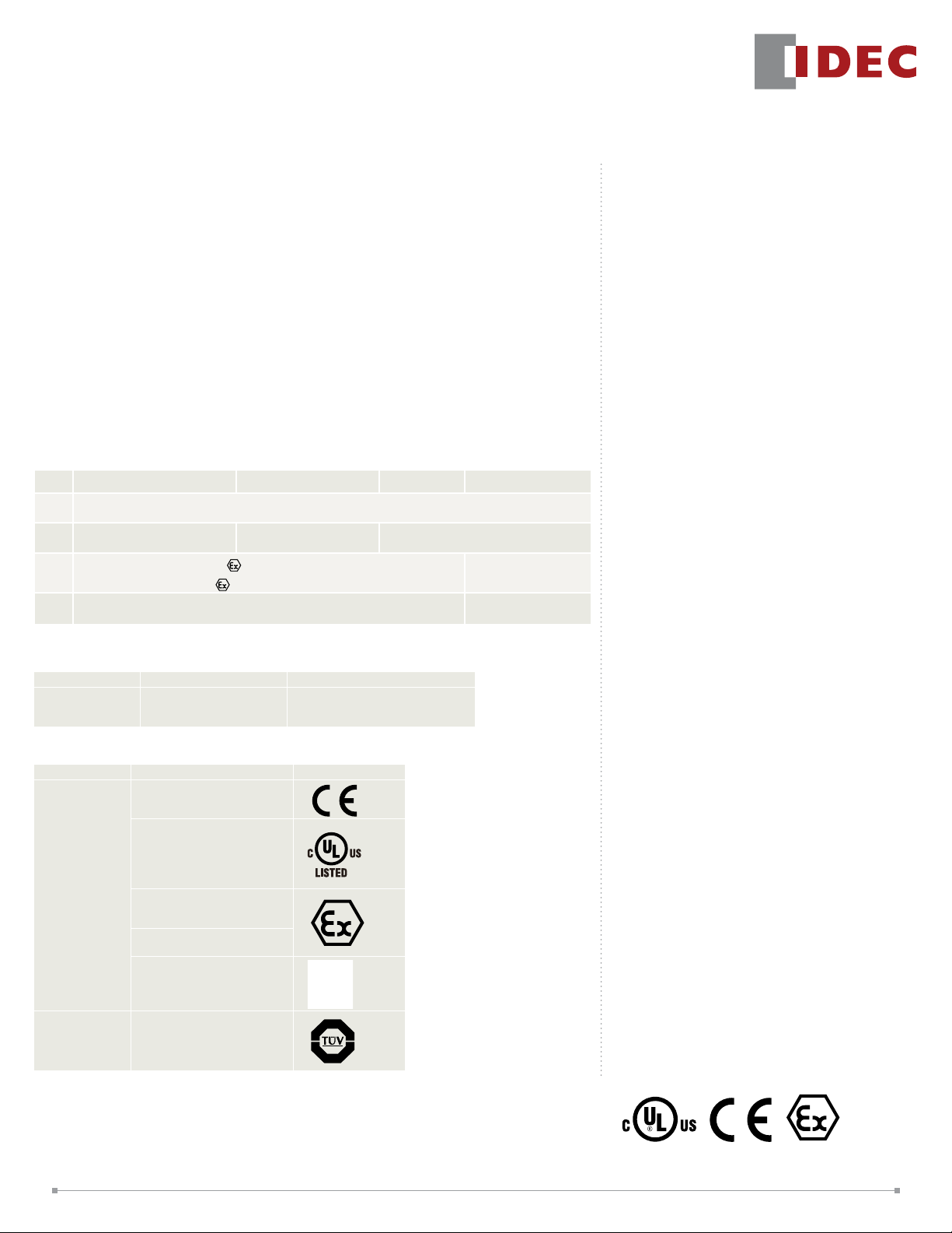
STANDARDS COMPLIANCE
Switches Pilot Lights Meters Control Boxes
UL
Class I, Zone 1, Ex de IIC T6 Gb
c-UL
Class I, Div 2, Groups A, B, C and D
ATE X
IECEx
Class I, Zone 1 AEx d e IIC T6 Gb
Class I Div 2, Groups A, B, C and D
Class I, Zone 1, Ex de IIB T6 Gb
Class I, Div 2, Groups C and D
II2G Ex de IIC Gb
II2D Ex tb IIIC Db IP65
Ex de IIC Gb
Ex tb IIIC Db IP65
Class I, Zone 1, Ex de IIC T6 Gb
Class I, Div 2, Groups A, B, C and D
Ex d e IIC T6 Gb
Ex tb IIIC T80ºC Db (dust)
Ex de IIC T6 Gb
Ex tb IIIC T80ºC Db (dust)
PRODUCT DESCRIPTION
Complying with UL, IECEx, and ATEX
Directives for hazardous environments,
new 30mm EU2B Hazardous Location
Switches and EC2B Hazardous Location
Control Stations provide increased safety
for your applications.
Control Unit Options:
• Pushbuttons
• Pilot Lights
• Selector Switches
• Key Selector Switches
• Emergency Stop Switches
• Meters
Control Station Options:
• Pre-congured stations
• Custom-congured stations
• Open control boxes
• Mounting holes for up to 18 control units
CERTIFICATE NUMBERS
UL/c-UL ATEX IECEx
E347230 PTB 08 ATEX 1053 U
PTB 08 ATEX 1003 U
PTB 08 ATEX 1048
IECEx PTB 15.0006U
IECEx PTB 15.0007U
IECEx PTB 15.0032
APPLICABLE STANDARDS
Control Units Standards Mark
EN60947-5-1
UL60079-0
Pushbuttons
Selector
Switches
Key Selector
Switches
Pilot Lights
Meters
Emergency
Stop Switches
UL 60079 -1
UL60079-7
CAN/CSA C22.2 No. 60079-0
CAN/CSA C22.2 No. 60079-1
CAN/CSA C22.2 No. 60079-7
EN60079-0 EN60079-1
EN60079-7 EN60079-31
IEC60079-0 IEC60079-1
IEC60079-7 IEC60079-31
EN60947-5-5
KEY FE ATURES
• Class I, Zone 1/Division 2
• Applicable in explosive gas atmospheres
(AEx de IIC T6 Gb)
• UL Type 4X rated
• Up to 3 contact blocks
• Selector switches available with lever or
key
• Selector switches available with
overlapping contacts
• Exposed and nger-safe (IP20) screw
terminals available
• Corrosion resistant stainless steel
enclosure (SUS304)
• Melamine coating
• NPT and Metric reducer options
1
Page 2

SPECIFICATIONS
General Specications
Degree of Pro tection
Insulation Resistance
Operating Temperature
Operating Humidity
Altitude
Pollution Degree
Shock Resis tance
Vibration Resistance
Switches
Rated Insulation Voltage
Contact Resistance
Impulse Wi thstand Voltage (Uimp)
Insulation Resistance
Short-Circuit Protection
Conditional Short-Circuit Current
Mechanical Life
Electrical Life
Minimum Operator
Stroke Required for
Direct Opening Action
Maximum Operator
Stroke
Note: Contacts will bounce during operation of pushbuttons and selector switches (reference value: 20-
ms). Be sure to take contact bounce time into consideration when designing a control circuit.
Contact Rating (Switches)
Rated Insulation Voltage (Ui)
Rated Thermal Curren t (It h)
Rated Operating Volt age (Ue)
AC
Rated Operating
Current (Ie)
Note: Up to 2 contacts (per control unit): 10A
3 contacts (per control unit): 9A
Minimum applicable load: 3V AC/DC, 5mA
Applicable operating locations may vary according to operating conditions and load types.
Contact
Rating Code
Designation
A600 10
50/60Hz
DC
Thermal
Continuous
Tes t
Current
Amperes
IP65 (IEC60529), Type 4X
100 MΩ minimum (500V DC megger)
−20 to +50°C (no freezing)
45 to 85% (no condensation)
2,000m Maximum
3
Operating Extremes
100-m/s²
Emergency Stop Switch:
150-m/s² (without Meter)
Damage Limits
1000-m/s²
5 to 55-Hz, amplitude 0.5 mm
Operating Extremes
Emergency Stop Switch:
5 to 500-Hz, amplitude 0.35-mm, acceleration
50-m/s² (without Meter)
30Hz, amplitude 1.5-mm
Damage Limits
Emergency Stop Switch:
5 to 500-Hz, amplitude 0.35-mm, acceleration
50-m/s²
600V
50mΩ maximum (initial value)
6kV
100MΩ minimum (500V DC megger)
250V/ 10A fu se
(Type aM IEC60269-1/IEC60269-2)
1,000A
Pushbutton
Selector Switch
Key Selector Switch
Emergency Stop Switch
Pushbutton
Selector Switch
Key Selector Switch
Emergency Stop Switch
Emergency Stop Switch
Emergency Stop Switch
1,000,000 operations minimum
500,000 operations minimum
500,000 operations minimum
50,000 operations minimum
250,000 (switching frequency 1800 operations/hr)
250,000 (switching frequency 900 operations/hr)
250,000 (switching frequency 900 operations/hr)
50,000 (switching frequency 900 operations/hr)
7.0mm
9.0mm
600V
10A*
24V 120V 240V 500V
Resisti ve Load (AC12)
Inductive Load ( AC15)
Resisti ve Load (DC12)
Inductive Load (DC13)
Maximum cur rent, Amperes
120 Volt 240 Volt 480 Volt 600 Volt 60 0 Volt
Make Break Make Break Make Break Make Break Make Break
60 6.00 30 3.00 15 1.5 12 1.2 7200 720
10A* 10A* 6A 2.8A
10A* 6A 3A 1.4A
8A 2.2A 1.1A —
4A 1.1A 0.55A —
Volt-Amperes
Maximum
Pilot Lights
Rated Insulation Voltage (Ui)
Rated Operating Volt age (Ue)
Impulse Wi thstand Voltage (Uimp)
Insulation Resistance
Frequency
Power Consumption (approx.)
Lif e (reference value)
Note: Because the built-in LED lamp is a high-brightness version, the lamp may light dimly due to induction
even when power is off.
Voltage
Transformer
Full Voltage
Transformer
500V
6V, 12V, 24V AC/DC
120V, 230V, 240V, 380V, 480V AC
4kV
100 MΩ minimum (500V DC)
50/60Hz
0.3W
1.5W
Approx. 40,000 hours
Meters
Accuracy Class
Insulation Resistance
Rated Insulation Voltage (Ui)
Operation
Impulse Wi thstand Voltage (Uimp)
Power Consumption
Measurement
AC ammeter
Input (CT Ratio)
Extended Memory
Rated Insulation Voltage (Ui)
Operation
Impulse Wi thstand Voltage (Uimp)
Input
DC input met er
Power Consumption (DC ammeter)
Consumption Current (DC voltmeter)
Note: Use a commercially available C T (current transfor mer) for all AC ammeters, and install the CT in a
non-hazardous location.
2.5
100 MΩ minimum (500V DC megger)
300V
Moving core
4kV
1VA
5A, 10A, 30A, 50A, etc
1A, 5A
3 times, etc
150V
Moving coil
2.5kV
0 to10V DC, 4 to 20mA, etc.
0.15 W
1mA
Control Boxes
Degree of protection
Housing Material
Standard Coating
Rated Insulation
Voltage
Insulation Resistance
Operating Temperature
Operating Humidity
Altitude
Agency Approvals
Applicable Enclosure
Mounting Style
Pilot Light
Pushbutton
Emergency Pushbutton
Selector Switch
Control Unit
Key Selector Switch
Meter
Reducer Screw
Degree of Pro tection
Grounding Terminal Screw Material
Stranded W ire (mm2)
Solid Wire (mm2)
Wire
Applicable
Solid/S tranded W ire (AWG)
1: c-UL explosion protection is different when pilot light is inst alled.
IP65 (IEC60529), Type 4X
Stainless steel (SUS304)
Melamine
1-column: Outside coating
2-, 3-column: Inside and outside coating
600V
(with pilot light or ET2A-8PE screw terminal block: 500V)
Meter AC input: 300V
Meter DC input: 150V
100 MΩ minimum (500V DC megger)
−20 to +50°C (no freezing)
45 to 85% (no condensation)
2000m maximum
UL/c-UL, IECEx/ATEX certied
All enclosures except for
6 Control Units x 3 Column
Wall Mount
1
Yes
Yes
Yes
Yes
Yes
Yes
NPT Thread (standard)
Metric Thread
IP65, TYPE4X (UL)
Stainless Steel
1.5 to 2.5
1.2 t o 1.6
16-14
2
Page 3
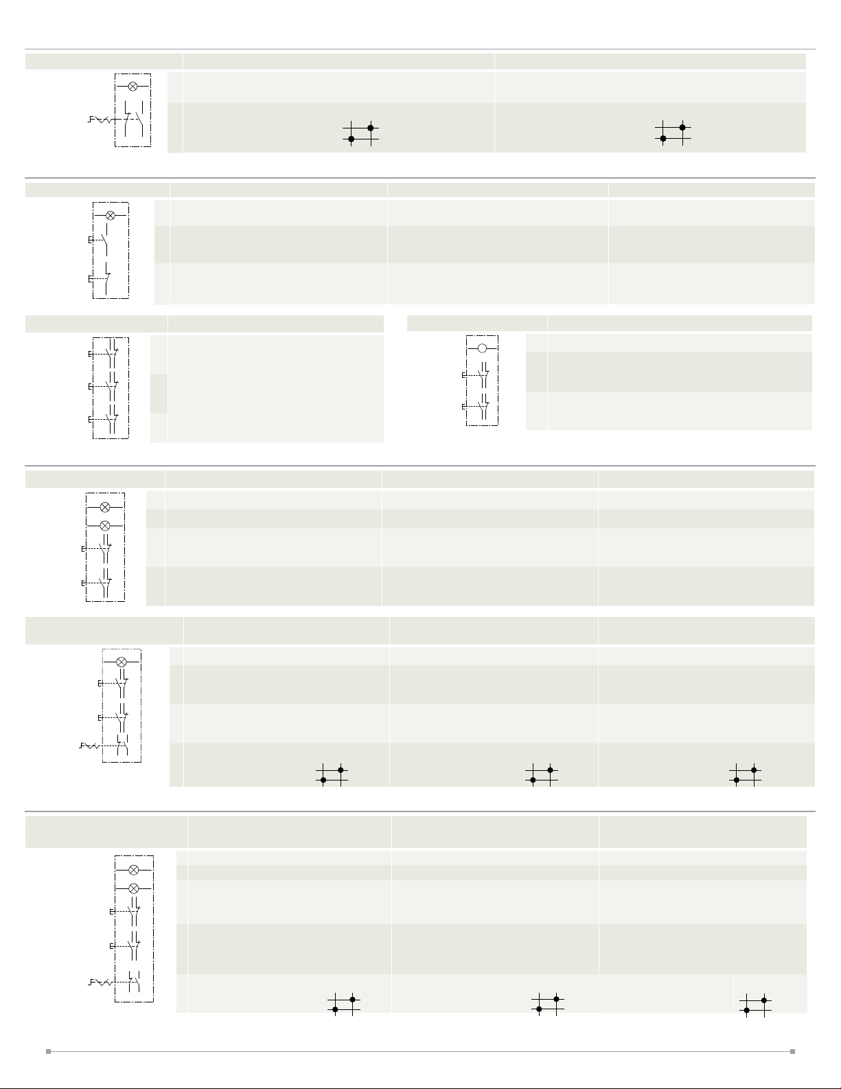
SWITCHES (CONTROL UNITS)
Pushbuttons Emergency Stop Switches Pilot Lights Selector Switches Key Selector Switches Meters
Pushbuttons
Operator (style / function)
B1 :Flush pushbutton / Momentary
B2 : Extended pushbutton / Momentary
B3 : Mushroom pushbutton / Momentary
Part Number
EU 2B-Y B110➃➀ –D
EU2B-YB101➃➀ –D
EU 2B-Y B111➃➀ –D
EU2B-YB120 ➃➀–D
EU2B-YB102➃➀ –D
EU2B-YB121➃➀ –D
EU 2B-Y B112➃➀–D
EU2B-YB130 ➃➀–D
EU2B-YB103➃➀ –D
EU2B-YB 210➃➀ –D
EU2B-YB 201➃➀ –D
EU 2B-Y B211➃➀ –D
EU2B-YB 220➃➀ –D
EU2B-YB 202➃➀–D
EU2B-YB 221➃➀ –D
EU2B-YB 212➃➀ –D
EU2B-YB230➃➀–D
EU2B-YB 203➃➀ –D
EU2B-YB 310➃➀ –D
EU2B-YB 301➃➀ –D
EU 2B-Y B311➃➀ –D
EU2B-YB320➃➀–D
EU2B-YB 302➃➀ –D
EU2B-YB 321➃➀ –D
EU2B-YB 312➃➀ –D
EU2B-YB330➃➀ –D
EU2B-YB303➃➀–D
Note: ➀ Button Color. Specify a contact terminal style in place of ➃ in the part number: F (Finger-safe
terminal), C (Exposed screw terminal)
EU2B - YB1 11 F S - D
Contact arrangement
10 : 1NO
20 : 2NO
30:3NO
11 : 1NO-1NC
21 : 2NO -1NC
St yle and
Function
Flush
Momentary
Extended
Momentary
Mushroom
Momentary
Arrangement
1NO
1NC
1NO-1NC
2NO
2NC
2NO-1NC
1NO-2NC
3NO
3NC
1NO
1NC
1NO-1NC
2NO
2NC
2NO-1NC
1NO-2NC
3NO
3NC
1NO
1NC
1NO-1NC
2NO
2NC
2NO-1NC
1NO-2NC
3NO
3NC
Contact
01 : 1NC
02 : 2NC
03 : 3NC
12 : 1NO -2NC
Weight
(Approx.)
68g
92g
116g
70g
94g
118g
76g
101g
125g
Button color
Blank: Red, Green, Black,
and White included
Y : Yellow S : Blue
Terminals
F : Finger-safe terminal (IP20)
C : Exposed screw terminal
➀ Button Color
➀ Blank - supplied with
red, green, black, and white
buttons
For yellow or blue buttons,
specify Y (yellow) or S
(blue).
Specify a button color code
in place of ➀ in the part
number
B : black
G : green
R : red
S : blue
W : white
Y : yellow
Emergency Stop Switches
EU2B - YBV3 11 F R
Operator (style / function)
BV3 : 40mm mushroom/push, pull or
twist release
Part Number Operator
EU2B-YB V301➃R
EU 2B-Y BV311➃ R
EU2B-YB V302➃R
ø40 Mushroom
EU2B-YB V312➃ R
EU2B-YB V303➃R
Specify a terminal st yle in place of ➃ in the part number: F (Finger-safe terminal), C (Exposed screw
terminal)
Contact arrangement
01 : 1NC
11 : 1NO-1NC
02 : 2NC
03 : 3NC
12 : 1NO -2NC
Contact
Arrangement
1NC 96g
1NO-1NC
2NC
1NO-2NC
3NC
Button color
R : Red
Terminals
F : Finger-safe terminal (IP20)
C : Exposed screw terminal
Weight
(Approx.)
120g
Button Color
R : Red
144g
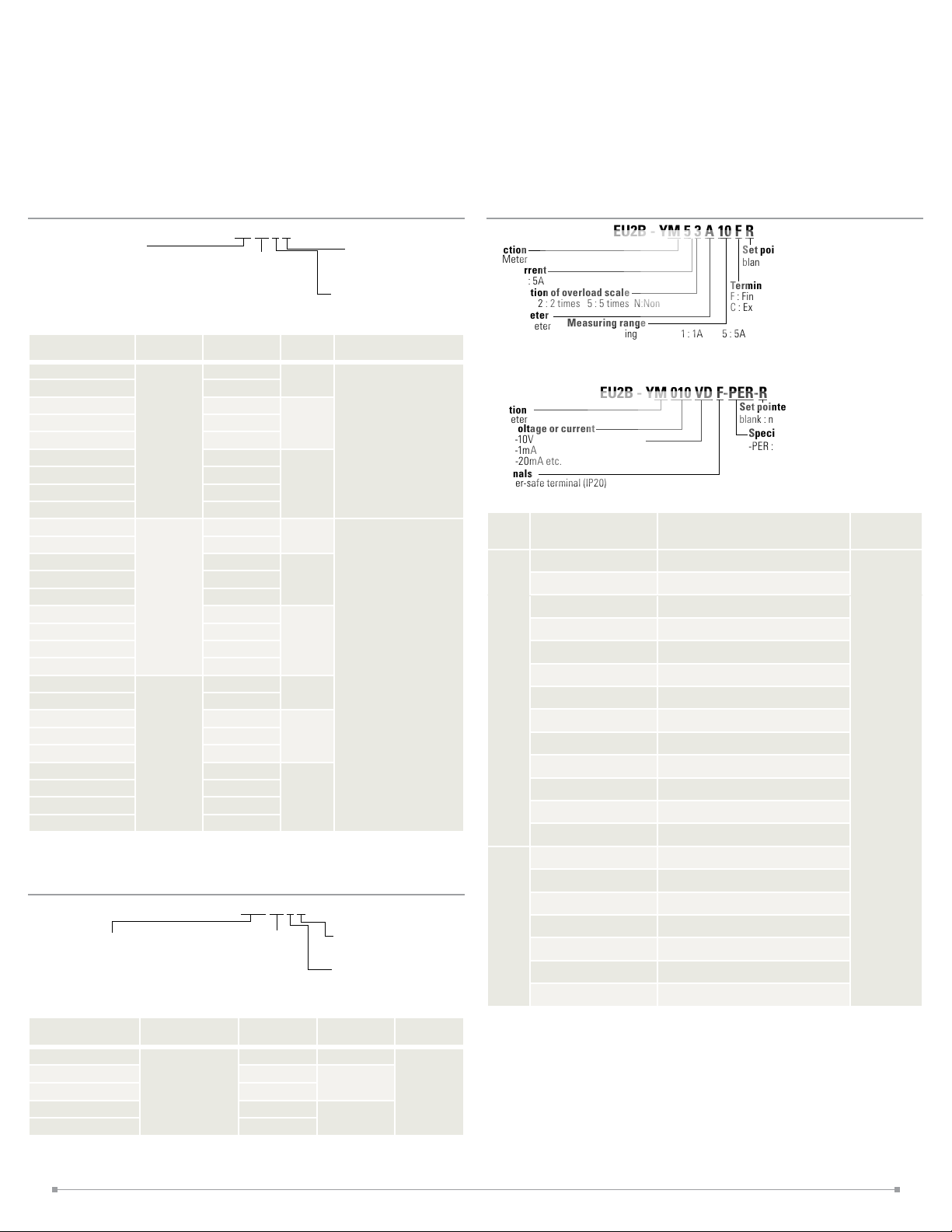
Meters
EU2B - YM 5 3 A 10 F R
Function
M : Meter
Input current
1 : 1A 5 : 5A
Specication of overload scale
3: 3 times 2 : 2 times 5: 5 times N:Non
Type of meter
A : AC ammeter
Measuring range
Direct measuring 1 : 1A 5 : 5A
For current transformers: 10 : 10A 15 : 15A 20 : 20A 30:30A 50:50A
60 : 60A 75 : 75A 100:100A 150:150A
EU2B - YM 010 VD F-PER-R
Function
M : Meter
Input voltage or current
010 : 0-10V
001 : 0-1mA
420 : 4-20mA etc.
Terminals
F : Finger-safe terminal (IP20)
C : Exposed screw terminal
Input Part Number
EU2B-YM53A5➃
EU2B-YM53A10➃
EU2B-YM13A10➃
EU2B-YM53A15➃
EU2B-YM13A15➃
EU2B-YM13A20➃
AC
input
meter
EU2B-YM53A30➃
(ammeter)
EU2B-YM13A30➃
EU2B-YM53A50➃
EU2B-YM53A60➃
EU2B-YM53A75➃
EU2B-YM53A100➃
EU2B-YM53A150➃
EU2B-YM010VD➃-PER
EU2B-YM010VD➃-60HZ
EU2B-YM001MD➃-PER
DC
input
EU2B-YM001MD➃-60HZ
meter
EU2B-YM001MD➃-80HZ
EU2B-YM420MD➃-PER
EU2B-YM420MD➃-60HZ
Specify a terminal style in place of ➃ in the part number: F (Finger-safe terminal), C (Exposed
screw terminal)
Type of meter
VD : DC voltmeter
MD : DC ammeter
Capacity: 5A Expansion scale: x3
Capacity:10/5A Expansion scale: x3
Capacity:10/1A Expansion scale: x3
Capacity:15/5A Expansion scale: x3
Capacity:15/1A Expansion scale: x3
Capacity:20/1A Expansion scale: x3
Capacity:30/5A Expansion scale: x3
Capacity:30/1A Expansion scale: x3
Capacity:50/5A Expansion scale: x3
Capacity:60/5A Expansion scale: x3
Capacity:75/5A Expansion scale: x3
Capacity:100/5A Expansion scale: x3
Capacity:150/5A Expansion scale: x3
0-10V DC Input Scale: 0 to 100%
0-10V DC Input Scale: 0 to 60Hz
0-1mA DC Input Scale: 0 to 100%
0-1mA DC Input Scale: 0 to 60Hz
0-1mA DC Input Scale: 0 to 80Hz
4-20mA DC Input Scale: 0 to 100%
4-20mA DC Input Scale: 0 to 60Hz
Set pointer
blank : non -R : with set pointer
Terminals
F : Finger-safe terminal (IP20)
C : Exposed screw terminal
Set pointer
blank : non -R : with set pointer
Specication of scale
-PER : 0~100%
-60HZ : 0~60Hz
-80HZ : 0~80Hz
Description
Weight
(approx.)
270g
3
Page 4
Pilot Lights
RL RL
Part Number Type
EU 2B-Y L1126 ➃D➀
EU2B-YL1236➃ D➀
EU2B-YL1246➃D➀
Transformer
EU2B-YL138 6➃D➀
EU2B-YL148 6➃D➀
EU2B-YL166 ➃D➀
EU 2B-Y L111➃D➀
Full Voltage
EU2B-YL122➃D➀
Note: ➀ Illumination Color. Specify a contact terminal style in place of ➃ in the part number: F (Finger-safe
terminal), C (Exposed screw terminal)
Operating
Voltage
120V AC
230V AC
240V AC
380V AC
480V AC
6V AC/DC
12V AC/DC
24V AC/DC
Weight
(Approx.)
150g
108g
➀ Illumination
Color Code
R : red
G : green
A : amber
Y : yellow
PW : white
S : blue
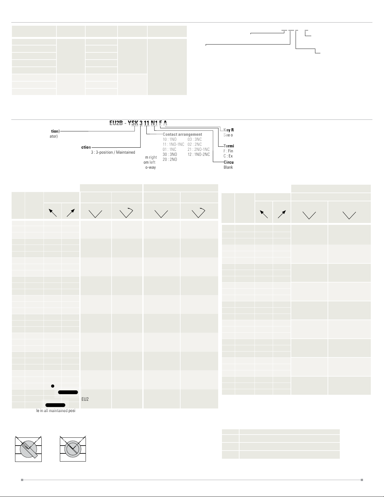
2 Position Selector Switches
EU2B - YSK 3 11 N1 F A
Operator (style / function)
S : Selector (Knob operator)
SK: Key selector (Key operator)
Number of Positions / Spring Return Action
2 : 2-position / Maintained
2R : 2-position / Maintained (Overlap)
2J : 2-position / Maintained (Special function)
21 : 2-position / Spring return from right
3 : 3-position / Maintained
31 : 3-position / Spring return from right
32 : 3-position / Spring return from left
33 : 3-position / Spring return two -way
Contact arrangement
10 : 1NO
11 : 1NO-1NC
01 : 1NC
30:3NO
20 : 2NO
Operating voltage
126 : AC 120V (Transformer t ype)
246 : AC 24 0V (Transformer type)
386 : AC 380V (Transformer type)
486 : AC 480V (Transformer type)
Key Removable Position
03 : 3NC
02 : 2NC
21 : 2NO -1NC
12 : 1NO -2NC
See option codes below
Terminals
F : Finger-safe terminal (IP20)
C : Exposed screw terminal
Circuit Number
Blank : No Designation
N* : See charts
EU2B - YL1 22 F D R
Operator (style / function)
L1 : Pilot Light / dome
66 : AC/DC 6V (Full voltage type)
11: AC/DC 12V (Full voltage type)
22 : AC/DC 24V (Full voltage ty pe)
Lens/LED Colors
R : Red G : Green A : Amber
Y : Yellow PW : White S : Blue
Terminals
F : Finger-safe terminal (IP20)
C : Exposed screw terminal
Con
-
Mount-
tact
NO 1
NC 3
NO 1
NO 3
NC 1
NC 3
NO 1
NC 3
NO 1
NO 2
NO 3
NC 1
NC 2
NC 3
NO 1
NO 2
NC 3
NO 1
NC 2
NC 3
Operator Position Maintained
ing
L
●
●
●
●
●
●
●
●
●
●
Selector Switches Key Selector Switches
R
●
R
L
EU2B-YS210 ➃ EU 2B-Y S2110➃
EU2B-YS201
●
➃ E U2B-YS2101➃
EU2B-YS220➃ EU2B-YS2120➃
●
EU2B-YS202➃ EU2B-YS2102➃
●
EU 2B-Y S211➃ EU2B -YS2111➃
●
●
EU2B-YS230➃ EU2B-YS2130 ➃
●
EU2B-YS203➃ EU2B-YS2103 ➃
●
●
EU2B-YS221➃ EU2B-YS2121➃
●
EU2B-YS212➃ EU2B-YS 2112➃
Spring Return
from Right
R
L
Maintained
L
EU2B-YSK210➃➂ EU2 B-YS K2110➃➂
EU2B-YSK2 01➃➂ EU 2B-YSK2101➃➂
EU2B-YSK2 20➃➂ EU 2B-YSK2120➃➂
EU2B-YSK2 02➃➂ EU 2B-YSK2102➃➂
EU 2B-Y SK2 11➃➂ E U2B -YSK 2111➃➂
EU2B-YSK230➃➂ EU2B-YSK2130➃➂
EU2B-YSK2 03➃➂ EU 2B-YSK2103➃➂
EU2B-YSK2 21➃➂ EU2B-YSK2121➃➂
EU2B-YSK212➃➂ EU2B -YSK 2112➃➂
R
Spring Return from
Right
L
NO 1
EU2B-YS2R11
N/A
➃
EU2B-YSK2R11➃➂
N/A
NC 2
Key is removable in all maintained positions. Specif y key removal position in place of ➂ in the par t number. See table.
Specify a terminal st yle in place of ➃ in the part number: F (Finger-safe terminal), C (Exposed screw terminal).
2-position, 2-position/inverse cam
Selector Switch Key Selector Switch
j
k
l
Contact
Block
Position
j
k
l
Contact
Block
Position
Operator Position Maintained Maintained
-
Mount-
R
Con
tact
ing
NO 1
R
L
●
EU2B-YS2J10➃
EU2B-YS2J01
NC 3
NO 1
●
●
EU2B-YS2J20➃
NO 3
NC 1
●
●
EU2B-YS2J02➃
NC 3
NO 1
●
●
EU 2B-Y S2J11➃
NC 3
NO 1
NO 2
NO 3
NC 1
NC 2
NC 3
NO 1
NO 2
NC 3
NO 1
NC 2
NC 3
●
●
●
●
●
●
●
●
●
●
●
●
●
EU2B-YS2J30➃
EU2B-YS2J03➃
EU2B-YS2J 21➃
EU2B-YS2J12➃
➂ Key Removable Option Codes (2-position)
Code Description
A Key removable in any position
B Key removable in left position
C Key removable in right position
Selector Switches Key Selector Switches
R
L
R
L
EU2B-YSK2 J10➃➂
EU2B-YSK2J01➃➂
➃
EU2B-YSK2 J20➃➂
EU2B-YSK2J02➃➂
EU 2B-Y SK2 J11➃➂
EU2B-YSK2J30➃➂
EU2B-YSK2J03➃➂
EU2B-YSK2 J21➃➂
EU2B-YSK2 J12➃➂
4
Page 5
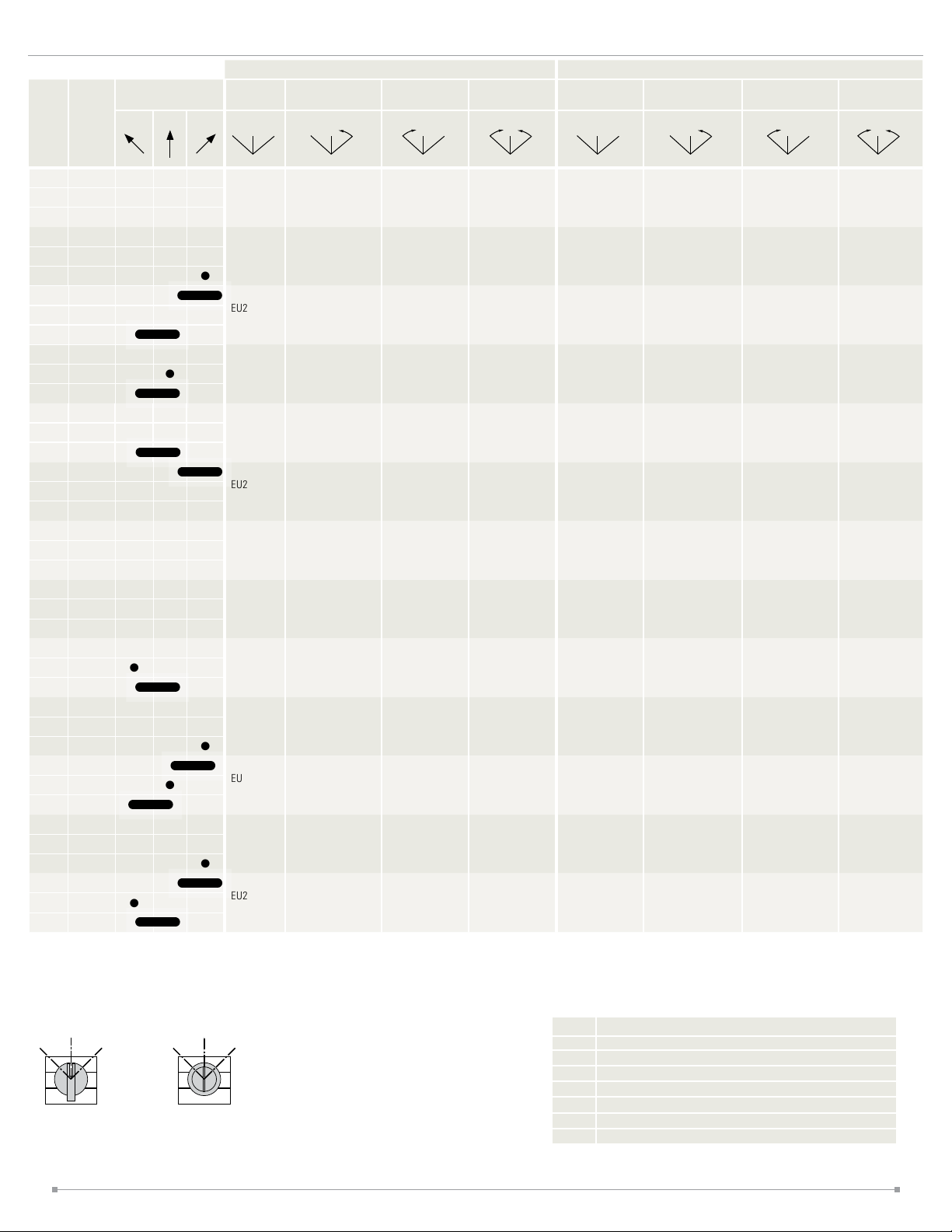
3 Position Selector Switches
C
C
Operator Position Maintained
Mount
Con
tact
-
-
ing
C
L
R
L C R
Selector Switches Key Selector Switches
Spring Return from
Right
L C R L C R
Spring Return
from Left
Spring Return Two
Way
L C R
Maintained
L C R
Spring Return from
Right
L C R L C R
Spring Return from
Left
Spring Return Two
Way
L C R
NO 1
NO 3
NO 2
NO 3
NC 1
NC 3
NC 2
NC 3
NO 1
NC 3
NC 1
NO 3
NO 1
NC 2
NC 2
NO 3
●
● ●
●
●
●
●
●
●
●
●
●
EU2BYS320➃
EU2BYS320N1➃
EU2BYS302➃
EU2BYS302N1➃
EU2BYS 311➃
EU2BYS 311N1➃
EU2BYS 311N2➃
EU2BYS 311N3 ➃
EU2B-YS3120 ➃ EU2B-YS3220➃ EU2B-YS3320➃ EU2B-YSK320➃➂ EU2 B-YSK3120➃➂ EU2B-YSK3220➃➂
EU2B-YS3120N1➃
EU2B-YS302➃ EU2B-YS3202➃ EU2B-YS3302➃ EU2B -YSK3 02➃➂ EU 2B-YSK3 02➃➂ EU2B-YSK3202➃➂
EU2BYS3102N1➃➂
EU 2B-Y S311➃ EU 2B-Y S32 11➃ EU2B-YS3311➃ EU 2B-Y SK311➃➂ E U2B -YSK 311➃➂ E U2B -YSK 3211➃➂
EU 2B-Y S3111N1➃
EU 2B-Y S3111N 2➃
EU 2B-Y S3111N 3➀
EU2BYS3220N1➃
EU2BYS3202N1➃➂
EU2BYS 3211N1➃
EU2BYS 3211N 2➃
EU2BYS 3211N 3➀
EU2BYS3320N1➃
EU2BYS3302N1➃
EU2BYS 3311N1➃
EU2BYS 3311N 2➃
EU2BYS 3311N 3➀
EU2BYSK320N1➃➂
EU2BYSK302N1➃➂
EU2BYSK3 11N1➃➂
EU2BYSK3 11N2➃➂
EU2BYSK3 11N3➃➂
EU2BYSK 3120N1➃➂
EU2BYSK3102N1➃➂
EU2BYSK3 111N1➃➂
EU2BYSK3 111N2➃➂
EU2BYSK3 111N3➃➂
EU2BYSK3220N1➃➂
EU2BYSK3202N1➃➂
EU2BYSK3 211N1➃➂
EU2BYSK3 211N2 ➃➂
EU2BYSK3 211N3 ➃➂
EU2BYSK3320➃➂
EU2BYSK3320N1➃➂
EU2BYSK3302➃➂
EU2BYSK3302N1➃➂
EU2BYSK3 311➃➂
EU2BYSK3 311N1➃➂
EU2BYSK3 311N2 ➃➂
EU2BYSK3 311N3 ➃➂
NO 2
● ●
EU2BYS 311N4 ➃
EU 2B-Y S3111N 4➃
EU2BYS 3211N 4➃
EU2BYS 3311N 4➃
NC 3
NO 1
NO 2
NO 3
NC 1
NC 2
●
● ●
●
EU2BYS330➃
EU2B-YS3130➃ EU2B-YS3230➃ EU2B-YS3330➃ EU2B-YSK330➃➂ EU 2B-YSK3130➃➂ EU2B-YSK3230➃➂
●
EU2BYS303➃
EU2B-YS3103➃ EU2B-YS3203➃ EU2B-YS3303➃ E U2B-Y SK30 3➃➂ EU2B-YSK 3103➃➂ EU2B-YSK3203➃➂
NC 3
NO 1
NC 2
NO 3
NC 1
NO 2
●
●
● ●
●
EU2B-YS3
21N1➃
EU2B-YS3
12N1➃
EU2B-YS3121N1➃
EU 2B-Y S3112 N1➃
EU2BYS3221N1➃
EU2BYS3212N1➃
EU2BYS33 21N1➃
EU2BYS3312N1➃
NC 3
Specify a terminal style in place of ➃ in the part number: F (Finger-safe terminal), C (Exposed screw terminal).
3-position, 3-position/inverse cam
Selector Switch Key Selector Switch
L R
j
k
l
Contact
Block
Position
L R
j
k
l
Contact
Block
Position
EU2BYSK3 11N4➃➂
EU2BYSK321N1➃➂
EU2BYSK 312N1➃➂
EU2BYSK3 111N4➃➂
EU2BYSK312 1N1➃➂
EU2BYSK3 112N1➃➂
EU2BYSK3 211N4 ➃➂
EU2BYSK3221N1➃➂
EU2BYSK 3212N1➃➂
EU2BYSK3 311N4 ➃➂
EU2BYSK3330➃➂
EU2BYSK3303➃➂
EU2BYSK3321N1➃➂
EU2BYSK 3312N1➃➂
Key is removable in all maintained positions. Specify key removal position in
place of ➂ in the part number. See table.
➂ Key Removable Option Codes (3-Position)
Code Description
A Key removable in any position
B Key removable in left and center positions
C Key removable in center and right positions
D Key removable in center position
E Key removable in left and right positions
G Key removable in left position
H Key removable in right position)
5
Page 6

CONTROL BOXES
OFF ON
OFF ON
1 control unit 2 control units 3 control units 4 control units 5 control units
EC2BB21B011N2➀-U
1 column
6 control units 9 control units 12 control units 15 control units 18 control units
EC2BB33B063N2➀-U
3 columns
EC2BB21B021N2➀-U
EC2BB33B093N2➀ -U
EC2BB31B031N2➀-U
EC2BB53B12 3N3➀ -U
EC2BB51B 041N3 ➀-U
EC2BB53B153N3➀-U
STANDARD CONTROL STATIONS
1 Control Unit × 1 Column
1 pushbutton
3 1
j
4 2
EC2B-1102BN2N1-U EC2B-1102BN2N2-U EC2B-1102BN2N3-U EC2B-1102BN2N4-U
Flush momentary
1NO contact
➀
Nameplate ON
Button color: black, green, red, and white
1NO-1NC contact
Flush momentary
1NC contact
Nameplate OFF
Button color: black, green, red, and white
EC2BB51B051N3➀ -U
EC2BB63B18 3N3➀ -U
4 control units 6 control units 8 control units 10 control units
EC2BB32B042N2➀-U
2 columns
Thread Size
Code Description Code Description
M1 M16 blank no terminal block
M2 M20 C Exposed screw terminals
M3 M25 F Finger-safe terminals
M4 M32
M5 M40
N1 NPT1/2
N2 NPT3/4
N3 NPT1
N4 NPT1 1/4
Flush momentary
1NO-1NC contact
Nameplate ON
Button color: black, green, red, and white
EC2BB32B062N2➀-U
➀ Terminal Block Style
Other thread size options available. To specify different
thread sizes, use table at left to select a code to use in
place of N2 or N3 in the part number.
Specify terminal block style in place of
(standard versions do not cont ain a terminal block).
EC2BB52B082N3➀-U
Flush momentary
1NO-1NC contact
Nameplate OFF
Button color: black, green, red, and white
EC2BB52B102N3➀-U
➀ in part number
1 pilot light
X1 X2
1 selector switch
OFF
1 3
ON
2 4
EC 2B-1101B N211-U E C2B -1101BN2 12-U EC2B -1101BN2 3-U EC2B -1101BN213- U EC 2B-1101B N214 -U EC2 B-1101BN 26-U
j
120V AC
➀
Illumination color: red
EC2B-1106BN2N1-U
Knob selector
2-position maintained
j
➀
1NO-1NC contact
Name plate
OFF-ON
2 Control Units × 1 Column
2 ush pushbuttons
3
4
1
2
1 pilot light/1 pushbutton
X1 X2
3 1
4 2
EC2B-2102BN2N1-U
Flush momentary
j
1NO contact, Nameplate ON
➀
Button color (black, green, red, and white buttons)
k
Flush momentary
1NC contact, Nameplate OFF
➁
Button color (black, green, red, and white buttons)
j
k
240V AC
Illumination color: red
1 key selector switch
EC 2B-2110B N2N5-U EC 2B-2110B N2N6-U EC 2B-2110B N2N 3-U
120V AC
➀
Illumination color: red
Flush momentary
1NO-1NC contact
➁
Name plate STOP
Button color (black, green, red, and white buttons)
24V AC/DC
Illumination color: red
1 3
ON
OFF
j
2 4
EC2B-1106BN2N4-U
Key selector
2-position maintained
(removable at all
➀
positions)
1NO-1NC contact
Nameplate OFF-ON
120V AC
Illumination color: green
2 Mushroom Pushbuttons
3 1
4 2
3 1
4 2
240V AC
Illumination color: red
Flush momentary
1NO-1NC contact
Name plate STOP
Button color (black, green, red, and white buttons)
j
k
240V AC
Illumination color: green
1 e-stop switch
EC2B-2102BN2N4-U
Mushroom momentary
➀
1NO-1NC contact, Nameplate ON
Button color (black)
Mushroom momentary
1NO-1NC contact, Nameplate OFF
Button color (red)
24V AC/DC
Illumination color: red
Flush momentary
1NO-1NC contact
Name plate STOP
Button color (black, green, red, and white buttons)
24V AC/DC
Illumination color: green
EC2B-1102BN2N7-U
121
Emergency stop switch
2NC contact
Nameplate EMER-
➀
j
GENCY STOP
2
Button color (red)
Specify terminal st yle code in place of in part no. C (standard screw terminal), F (nger-safe screw terminal)
6
Page 7
2 Control Units × 1 Column
OFF ON
OFF ON
HAND AUTO
HAND AUTO
HAND AUTO
HAND AUT
O
HAND AUT
O
HAND AUTO
1 pilot light / 1 selector switch
X1 X2
j
1 3
ON
OFF
2 4
➀
k
➁
3 Control Units × 1 Column
1 pilot light / 2 pushbuttons
X1 X2
j
4
3
2
1
➀
k
➁
l
➂
EC2B-2117BN2N3-U EC2B-2117BN2N4-U
120V AC
Illumination color: red
Knob, 2-position,
1NO-1NC contact
Maintained, Name plate OFF-ON
240V AC
Illumination color: red
Knob, 2-position,
1NO-1NC contact
Maintained, Name plate OFF-ON
EC 2B- 3110B N2N 5-U EC 2B- 3110B N2N 6-U EC 2B- 3110B N2N 3-U
120V AC
Illumination color: red
Flush momentary
1NO contact, Nameplate ON
Button color (black, green, red, and white buttons)
Flush momentary
1NC contact, Nameplate OFF
Button color (black, green, red, and white buttons)
240V AC
Illumination color: red
Flush momentary
1NO contact, Nameplate ON
Button color (black, green, red, and white buttons)
Flush momentary
1NC contact, Nameplate OFF
Button color (black, green, red, and white buttons)
24V AC/DC
Illumination color: red
Flush momentary
1NO contact, Nameplate ON
Button color (black, green, red, and white buttons)
Flush momentary
1NC contact, Nameplate OFF
Button color (black, green, red, and white buttons)
3 pushbuttons
3 1
4 2
3 1
4 2
3 1
4 2
EC2B-3102BN2N1-U
➀
j
Flush momentary
1NO-1NC contact,
k
➁
Blank nameplate
Button color (black, green, red, and white buttons)
l
➂
4 Control Units × 1 Column
2 pilot lights / 2 pushbuttons
X1 X2
X1 X2
3 1
4 2
3 1
4 2
1 pilot light / 2 pushbuttons /
1selectorswitch
X1 X2
3 1
4 2
3 1
4 2
AUTO
HAND
31
EC 2B- 4110B N3N 5-U EC 2B- 4110B N3N 6-U EC 2B- 4110B N3N 3-U
➀
120V AC, Illumination color: red 240V AC, Illumination color: red 24V AC/DC, Illumination color: red
j
➁
120V AC, Illumination color: green 240V AC, Illumination color: green 24V AC/DC, Illumination color: green
k
Flush momentary
➂
1NO-1NC contact, Nameplate ON
l
Button color (black, green, red, and white buttons)
Flush momentary
m
➃
1NO-1NC contact, Nameplate OFF
Button color (black, green, red, and white buttons)
➀
j
k
➁
l
➂
m
➃
1 meter / 2 pushbuttons
j
3A1
k
4 2
3 1
l
4 2
Specify the meter's capacity and scale in place of in the part number
Flush momentary
1NO-1NC contact, Nameplate ON
Button color (black, green, red, and white buttons)
Flush momentary
1NO-1NC contact, Nameplate OFF
Button color (black, green, red, and white buttons)
EC2B-3152BN2N1-U
➀
Specify input, capacity, and scale
Flush momentary
➁
1NO-1NC contact, Nameplate ON
Button color (black, green, red, and white buttons)
Flush momentary
➂
1NO-1NC contact, Nameplate OFF
Button color (black, green, red, and white buttons)
Flush momentary
1NO-1NC contact, Nameplate ON
Button color (black, green, red, and white buttons)
Flush momentary
1NO-1NC contact, Nameplate OFF
Button color (black, green, red, and white buttons)
EC 2B- 4113B N3N 5-U EC 2B- 4113B N3N 6-U EC 2B- 4113B N3N 3-U
120V AC, Illumination color: red 240V AC, Illumination color: red 24V AC/DC, Illumination color: red
Flush momentary
1NO-1NC contact, Nameplate ON
Button color (black, green, red, and white buttons)
Flush momentary
1NO-1NC contact, Nameplate OFF
Button color (black, green, red, and white buttons)
Knob, 2-position, maintained
1NO-1NC contact
Nameplate HAND-AUTO
Flush momentary
1NO-1NC contact, Nameplate ON
Button color (black, green, red, and white buttons)
Flush momentary
1NO-1NC contact, Nameplate OFF
Button color (black, green, red, and white buttons)
Knob, 2-position, maintained
1NO-1NC contact
Nameplate HAND-AUTO
Flush momentary
1NO-1NC contact, Nameplate ON
Button color (black, green, red, and white buttons)
Flush momentary
1NO-1NC contact, Nameplate OFF
Button color (black, green, red, and white buttons)
Knob, 2-position, maintained
1NO-1NC contact
Nameplate HAND-AUTO
5 Control Units × 1 Column
2 pilot lights / 2 pushbuttons /
1selectorswitch
X1 X2
X1 X2
3 1
4 2
3 1
4 2
2 4
ON
OFF
1 3
Specify terminal st yle code in place of in part no. C (standard screw terminal), F (nger-safe screw terminal)
EC 2B- 5113BN3 N5-U EC2 B-5113BN3N 6-U EC2B -5113BN3N3-U
➀
120V AC, Illumination color: red 240V AC, Illumination color: red 24V AC/DC, Illumination color: red
j
➁
120V AC, Illumination color: green 240V AC, Illumination color: green 24V AC/DC, Illumination color: green
k
Flush momentary
➂
1NO-1NC contact, Nameplate ON
l
Button color (black, green, red, and white buttons)
Flush momentary
m
➃
1NO-1NC contact, Nameplate OFF
Button color (black, green, red, and white buttons)
n
Knob, 2-position, Maintained,
➄
1NO-1NC contact,
Name plate HAND-AUTO
Flush momentary
1NO-1NC contact, Nameplate ON
Button color (black, green, red, and white buttons)
Flush momentary
1NO-1NC contact, Nameplate OFF
Button color (black, green, red, and white buttons)
Knob, 2-position, Maintained,
1NO-1NC contact
Name plate HAND-AUTO
7
Flush momentary
1NO-1NC contact, Nameplate ON
Button color (black, green, red, and white buttons)
Flush momentary
1NO-1NC contact, Nameplate OFF
Button color black, green, red, and white buttons)
Knob, 2-position, Maintained,
1NO-1NC contact
Name plate HAND-AUTO
Page 8

DIMENSIONS
Flush
ø40
39.0
67.7
All dimensions in mm
Control Units
Pushbuttons
Shown with finger-safe contacts
32.2
ø 40.0
13.3
Emergency Stop Switches
Shown with finger-safe contacts
32.2
47.4
ø 40.0
13.3
1.0 to 4.5 (panel thickness)
Mushroom
33.0
ø40
48.0
1.0 to 4.5 (panel thickness)
35.0 67.7
67.7
24.5
Extended
ø 24.0
Pilot Lights
Shown with finger-safe contacts
61.4
19.3
Meters
Shown with finger-safe contacts
38.4
32.5
32.0
ø 40.0
1.0 to 4.5 (panel thickness)
20.3
ø 40.0
67.7
62.0
67.720.3
8.0
1.0 to 4.5 (Panel thickness)
ø 28.0
Selector Switches
Shown with finger-safe contacts
32.2
47.4
Key Selector Switch
Shown with finger-safe contacts
32.2
47.4
ø 40.0
37.3 67.7
ø 40.0
27.3
1.0 to 4.5 (panel thickness)
1.0 to 4.5 (panel thickness)
67.7
38.4
ø 64.0
33.5 62.1
38.4
Mounting Hole Dimensions
+0.2
4.8
ø
30.5
+0.5
0
0
50 min (*note)
0
+0.5
33
70 min
Panel thickness: 1.0 to 4.5 mm.
*Note: The meter can be mounted on the top mounting holes of a standard 50mm mounting cen-
ters. The meter can be mounted on any mounting hole with a 70mm or larger mounting center.
8
Page 9
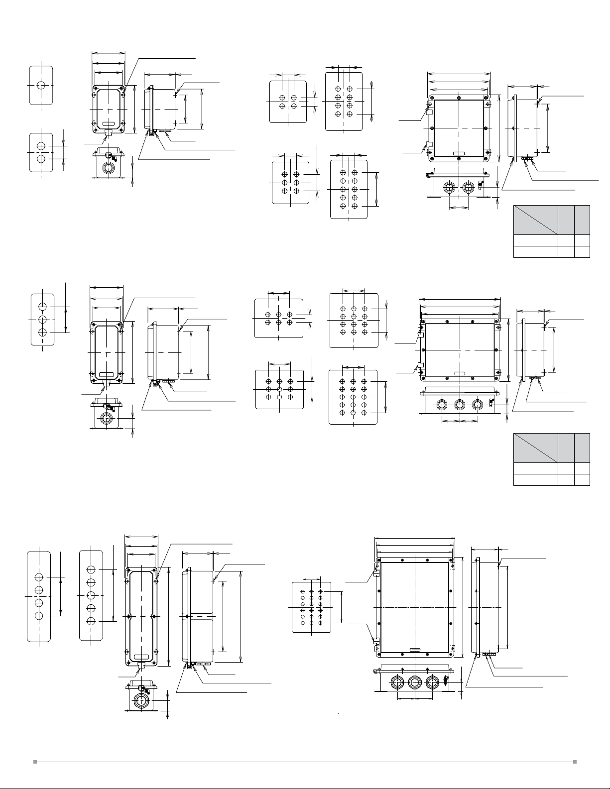
1, 2 control units x 1 column
weight: 1.2kg/1.4kg
Hinge
115
110
95
(mounting
hole)
1 control unit
2 control units
50
3 control units x 1 column
weight: 1.8kg
3 control units
2×50P
115
110
95
(mounting
hole)
4-ø7 (mounting hole)
10 6
170
Reducer
M4 grounding terminal
M5 lid mounting screw
36
4-ø7 (mounting hole)
106 1.5
220
1.5
Mounting tab
hole )
142
100
(mountin g
Mounting tab
hole)
150
(mounting
192
2, 3, 4, 5 control units x 2 columns
weight: 3.8/4.2/4.6/5.0 kg
4 control units
2 control units
70
3 control units
70
50
5 control units
2×50P
70
70
2, 3, 4, 5 control units x 3 columns
weight: 4.8/5.2/6.5/7.1 kg
50
2×50P
4 control units
140
5 control units
140
2 control units
140
3 control units
140
3×50P
4×50P
3×50P
(mounting hole)
4-ø10
(mounting
hole)
Hinge
10
4-ø
Hinge
230
220
210
2106
Mounting tab
A
R
(mounting
hole)
Reducer
36.5
70
M4 grounding terminal
M5 lid mounting screw
Dimensions
No. of
Control Units
A R
2 or 3 250 180
4 or 5 350 280
320
310
300
106
2
Mounting tab
A
R
(mounting
hole)
Hinge
4, 5 control units x 1 column
weight: 2.4kg
4 control units
5 control units
3x50P
4x40P
Hinge
36
115
110
95
(mounting
hole)
Reducer
M4 grounding terminal
M5 lid mounting screw
4-ø7 (mounting hole)
350
M5 lid mounting screw
36
1.5106
Mounting tab
322
250
hole)
(mounting
Reducer
M4 grounding terminal
6 control units x 3 columns
weight: 8.1kg
Control Unit
Mounting Holes
140
4-ø10
(mounting
5×50P
Hinge
hole)
4×50P
36.5
7070
Reducer
M4 grounding terminal
M5 lid mounting screw
Dimensions
No. of
Control Units
A R
2 or 3 250 180
4 or 5 350 280
320
310
300
70
70
106
2
Mounting tab
400
Reducer
36.5
M4 grounding terminal
M5 lid mounting screw
hole)
330
(mounting
9
Page 10

Terminal Blocks
Marking Plate
40
(6.5)
Insert
➀
Terminal blocks are not supplied with the standard control boxes (without wiring). When wiring
inside the control box is required, specify the wiring circuit. The terminal block type used on the
control boxes with wiring depends on the terminal style of the control unit.
C terminal style
exposed screw terminal
ET2A-8PE
polyamide
IECEx TUR 15.0043U,
TÜV 15 ATE X 7799U
34
22
101
123
F terminal style
nger-safe screw terminal
IP20 clamp terminal: 264-238 (WAGO)
polyamide
IECEx PTB 04.0003U, PTB 98 ATEX
3129 U
The number of terminal blocks, poles, and the installation direction that can be installed on the
control box are as follows:
1-column 1, 2 units
(1 terminal block
1-column 3 units
(1 terminal block
/8 poles)
/ 8 poles)
32
22
1-column 4, 5 units
(1 terminal block
/ 8 poles)
84
96
2-column 2, 3 units
(2 terminal blocks
/16 poles)
Fittings and Reducers
Reducers installed at the bottom of the control box are as follows: 1 column: 1 reducer, 2 columns: 2 reducers, 3 columns: 3 reducers. Material is nickel-plated brass. Use cable lead-in ttings
that are commercially available. See the following table for optional reducers
Control Box St yle Par t No. Thread Size Symbol UL c-UL
EC9E-H3M16E-UL M16 M1
1 column
(1 to 3 control units)
2, 3 columns
(2, 3 control units)
1, 2, 3 columns
(4, 5 control units)
3 columns
(6 control units)
: Standard reducer
EC9E-H3M20E-UL M20 M2
EC9E-H3M25E
EC9E-H3M32E
EC9E-H3NPT1E
EC9E-H3NPT2E
EC9E-H3NPT3E
EC9E-H4M25E
EC9E-H4M32E
EC9E-H4M40E
EC9E-H4NPT2E
EC9E-H4NPT3E
EC9E-H4NPT4E
: non-standard reducer
-UL M25 M3
-UL M32 M4
-UL NP T 1/2 N1
-UL NPT 3/4 N2
-UL NPT 1 N3
-UL M25 M3
-UL M32 M4
-UL M40 M5
-UL NPT 3/4 N2
-UL NPT 1 N3
-UL NPT 1 1/4 N4
The reducers in the table above are for replacement use only. All EC2B boxes are supplied with
a reducer that has been secured to the housing per UL regulations. If it is necessary to replace a
reducer, the user should follow appropriate UL standards for securing to EC2B housing.
.
2-column 4,5 units
(4 terminal blocks/ 32
poles)
3-column 2, 3 units
(3 terminal blocks/ 24
poles)
3-column 4, 5, 6 units
(6 terminal blocks/ 8
poles)
ACCESSORIES
All dimensions in mm
Nameplates
Used for pilot light, pushbutton, selector switch, and key selector switch.
Appearance Part Number Dimensions
(35)
EU9Z-NM
ø40
Nameplate Inserts
Appearance Legend Part Number
Blank EU9Z-NP0
ON EU9Z-NP1
4.5
OFF EU9Z-NP2
START EU9Z-NP3
28.5
STOP EU9Z-NP4
OFF-ON EU9Z-NP31
HAND-AUTO EU9Z-NP35
1.5
HAND-OFF-AUTO EU9Z-NP53
Material: Aluminum
Inst alling the Insert to the Nameplate Removing the Inser t from the Nameplate
➁
Flat screwdriver
Insert
Nameplate
To remove the Insert, insert a at screwdriver between the Insert and Nameplate.
10
Page 11

Rubber Boots
ø58
ø40.5
32.1
Base
(panel thickness)
23.2
Appearance Description/Usage Part Number
For Flush Pushbuttons
Not for use with name plate EU9Z-DB1
Emergency Stop Switch Padlock Cover
Used with EU2B-YBV emergency stop switch to maintain the switch in the latched status.
Appearance Part Number Dimensions
For Flush Pushbuttons
For use with name plate EU9Z-DB1N
For Extended Pushbuttons
Not for use with name plate EU9Z-DB2
For Extended Pushbuttons
For use with name plate EU9Z-DB2N
Emergency Stop Switch Nameplate Stickers
Appearance Legend Part Number Dimensions
Blank EU9Z-NVS0
ø58
ø40.5
EU9Z-PCE
50
55.4
Coating: yellow Material: Stainless Steel
Mounting Hole Plug
Used to plug unused mounting holes (ø30.5) on the mounting panel.
Appearance Part Number Dimensions / Usage
EU9Z-BP
13.3
ø40
1.0 to 10.5
Buttons
Appearance Style Part Number Button Color Code
Flush
HW1A-B1➀
46
8
32.2
Emergency
Stop
Material: yellow synthetic paper Legend: black
EU9Z-NVS27
Padlock Cover
EU2B-YB2 extended pushbutton: to maintain latched status
EU2B-YB1 flush pushbutton/EU2B-YSK key selector switch: to prevent operation
Appearance
Note: mounted to outside of enclosure with screws, not provided by IDEC
Material: Stainless Steel
Part
Number
EU9Z-PC
Dimensions
8
44
Specify a color code in place of ➀
in the Ordering Number.
ø58
ø40.5
Material: Polyacetal
Extended
ø40 Mushroom
HW1A-B2➀
HW1A-B4➀
R : red
G : green
B : black
Y : yellow
W : white
S : blue
Lenses
Appearance Lens Color Part Number
Red EU9Z-LR
Green EU9Z-LG
Amber EU9Z-LA
46
24.5
Material: AS resin (gasket supplied)
Yellow EU9Z-LY
White EU9Z-LW
Blue EU9Z-LS
11
Page 12

LED Lamps
Control Box Shade
Operating
Voltage
6V AC/
DC±10%
12V AC/
DC±10%
24V AC/
DC±10%
Current Draw
AC DC
7mA
(A, R, W)
8mA
5.5mA
(G, PW, S)
11mA 10mA
11mA 10mA
Part
Number
LSTD-6➀
LSTD-1➀
LSTD-2➀
Illumination Color Code Base
Specify a color code in place
of ➀ in the part number
R : red
G : green
A : amber
PW : white
S : blue
Use a white (PW) LED with
yellow (Y) lens.
BA9S/13
OPERATING INSTRUCTIONS
Installation Area
Do not install the EC2B control box in an environment where more than IP65 protection degree
(more than Type 4X in North America) is required.
Use the EC2B control box under ambient temperature of –20 to +50°C. If the control box is
exposed to direct sunlight and the surface temperature may rise above 50°C, provide a shade to
keep the surface temperature below 50°C.
Installation
Use four M6 bolts for 1-column, four M8 bolts for 2- and 3-column, or other methods with
equivalent strength to install the control box. Mounting tab thickness is 1.5mm for 1 column and
2mm for 2, 3, and 4 columns.
• If bolts become may loose due to vibration, use spring washers.
• If bolt corrosion is anticipated, use anti-corrosion bolts or other countermeasures.
Notes on Emergency Stop Switches
When using the emergency stop switches on safety-related parts of the control system, observe
safety standards and regulations of the relevant country or region. Also be sure to perform a risk
assessment before operation.
Opening/Closing the Lid
Use a Philips screwdriver to loosen lid mounting screws. While holding the unhinged side, open
the lid slowly without exerting excessive force on the hinge.
Before closing the lid, make sure of the following:
• No foreign substances are on the packing or joint surfaces.
• No displacement of the waterproof packing.
• Wires are not caught between the joint surfaces.
• Next, close the lid slowly and tighten the screws to a proper torque of 1.6 to 2.4 N·m.
Limitation of the Operating Current
Major heat sources comes from the wiring which is connected to the control box. Therefore,
not only the operating current but wiring conditions (size, no. of wires, no. of wire bundles) may
cause temperature rise. When wiring, observe the following conditions.
Stranded wire: 1.5 to 2.5 mm2 (UL-c-UL certified) / Solid wire: ø1.2 to ø1.6 mm (16 to 14 AWG)
• Maximum no. of wires per bundle: 16
• Maximum operating current: 10A
When using the control box under an operating environment of 40°C minimum, use a heat
resistant cable of 70°C minimum.
Shape Part No.
D
H
Material: stainless steel
Thickness: 1mm
Photo: Part No. EC9Z-F2A52
Protects control units from direct sunlight and rain. The sur face of the control box shade is uncoated.
Can be installed by tightening to the mounting tabs on the control box.
W
EC9Z-F2A21M
EC9Z-F2A31M EC2B-31*B 230 160 160
EC9Z-F2A51
EC9Z-F2A32
EC9Z-F2A52
EC9Z-F2A33
EC9Z-F2A53
EC9Z-F2A63 EC2B-63*B 410 510 160
Applicable
Control Box
EC 2B-11*B
EC2B -21*B
EC2B -41*B
EC2B -51*B
EC2B-22*B
EC2B-32*B
EC2B-42*B
EC2B-52*B
EC2B-23*B
EC2B-33*B
EC2B-43*B
EC2B-53*B
Determine the operating current so that the total heat value of 1 wire bundle is below 300 [A
Also, when calculating the heat value, take the current fluctuation (10%) into consider-
wires].
ation.
[calculation example: EC2B-41**B (8 circuit)]
➀ Apply 10A to 1 circuit, 1A to the remaining 7 circuits:
Dimensions (mm)
H W D
180 160 160
360 160 160
260 420 160
360 420 160
260 510 160
360 510 160
2
×
{(10A × 1.1)2 × 2 wires} + {(1A ×1.1)2 × 14 wires} ≈ 259 (can be used because < 300)
➁ Apply 10A to 1 circuit, 2A to the remaining 7 circuits:
{(10A × 1.1)2 × 2 wires} + {(2A × 1.1)2× 14 wires} ≈ 310 (cannot be used because > 300)
See the table below for the allowable operating current when applying current evenly to each
control box.
Allowable Operating Current
Control
Box
Part No.
EC 2B-11 3 16 (16×1) 8 (8×1) 7A
EC2B-21 6 16 (16×1) 8 (8×1) 5A
EC2B-31 9 16 (16×1) 8 (8×1) 4A
EC2B-41 12 16 (16×1) 16 (16×1) 3A
EC2B-51 15 16 (16×1) 16 (16×1) 3A
EC2B-22 12 32 (16×2) 16 (8×2) 5A
EC2B-32 18 32 (16 ×2) 16 (8×2) 4A
EC2B-42 24 32 (16×2) 32 (16×2) 3A
EC2B-52 30 32 (16×2) 32 (16× 2) 3A
EC2B-23 18 48 (16× 3) 24 (8×3) 5A
EC2B-33 27 48 (16×3) 24 (8×3) 4A
EC2B-43 36 48 (16× 3) 48 (16×3) 3A
EC2B-53 45 48 (16×3) 48 (16× 3) 3A
EC2B-63 54 48 (16x3) 4 8 (16x3) 3A
*1: Make sure that the number of wires per bundle is a maximum of 16 by reducing the wiring or by jumper
wiring. The maximum number of wires per bundle may need to be further reduced depending on the
wire size, lead-in tting, or conduit size.
*2: The allowable current value (reference) when applying current evenly to all circuits of the maximum
number of circuits.
Max.
No. of
Circuits
Max No. of Wires per Bundle (*1)
[wires] ([wires]×[bundle])
Without terminalblocks
With terminal
blocks
Allowable Operating
Current
(reference) (*2)
12
Page 13
Wiring
Insulation Sheath
All dimensions in mm.
Wiring Construction
Observe the laws and regulations in each country concerning wiring construction.Use cable
wiring or metal conduit wiring for installation in hazardous locations. If foreign objects or water
may enter the box, install a sealing fitting near the cable entry of the box and seal the control box
using a compound. Standard type control boxes do not contain a terminal block. Wire the control
units directly.
Applicable Wires
Stranded wire: 1.25 to 2.5 mm2, solid wire: ø1.2 to ø1.6 mm (AWG16 to 14). Do not connect more
than 2 wires to the same terminal.
Applicable crimping terminal
Ring and spade terminals cannot be used for EU2B control units with IP20 finger-safe terminals.
Ring and spade terminals cannot be used for IP20 clamp type terminal blocks. When connecting
two ferrules to an EU2B control unit, use ferrules without insulating sheath.
(Spade terminal) (Ring terminal) (Ferrule)
6.9 max.
3.6 min
3.4 max. 5.5 min.
6.9 max.
ø3.6min.
5.5 min.
For screw terminal ET2A-8PE For IP20 clamp terminal
(WAGO: 264-238)
(Ring terminal)
Without
insulating
sheath
∗£1.8 max.
8.0 max.
With
insulating
sheath
∗£1.8 max.
∗ Dimensions after crimping
8.0 max.
Insulation
sheath
Wire
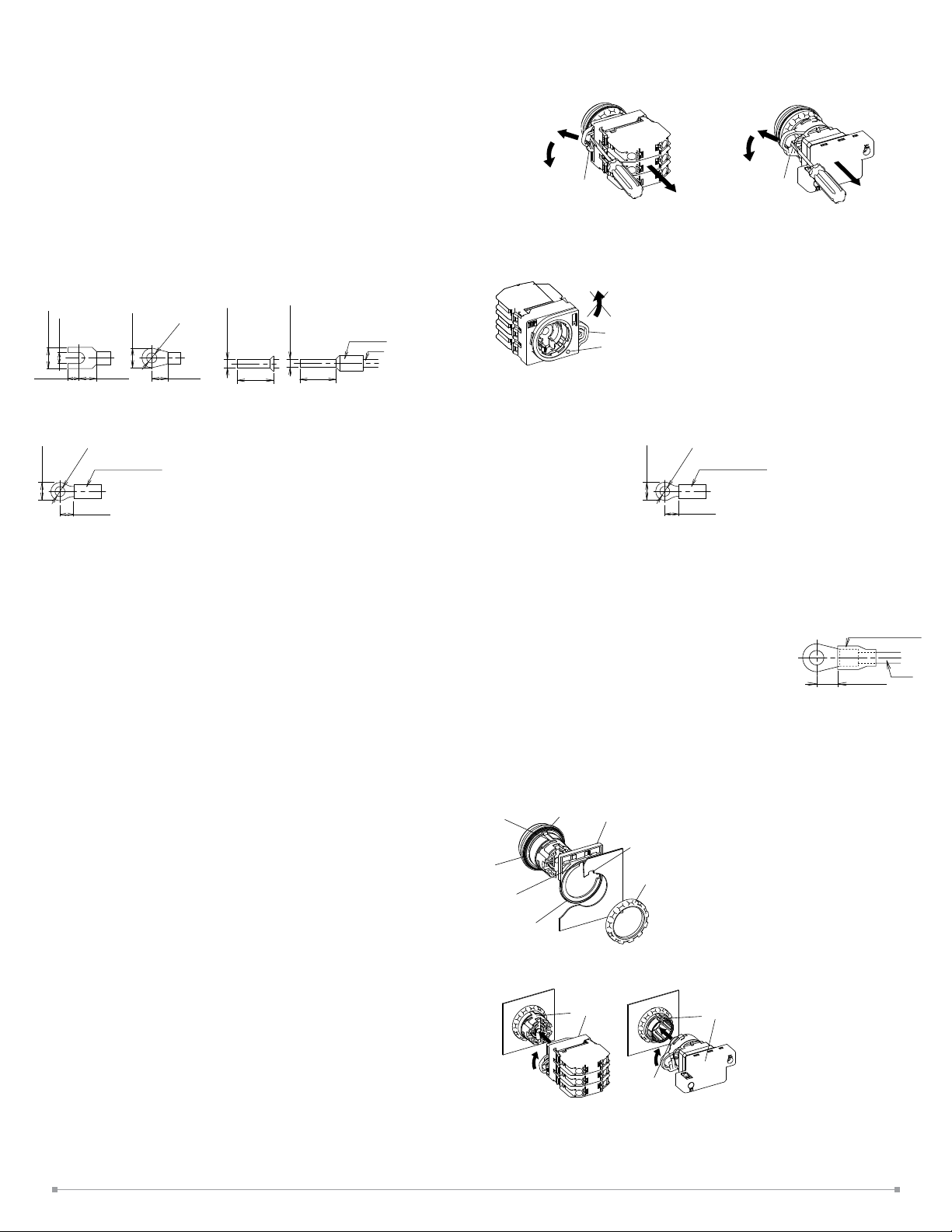
Removing and Installing the Contact Unit / Lamp Unit
To remove the contact unit or the lamp unit from the operator, pull the protruding yellow part of
the locking lever outwards as shown in the figure below using a screwdriver, and turn it to the
left. The contact unit or lamp unit can be removed.
➁
(Turn)
locking lever
(Lift)
➀
TOP
➂
(Pull)
EU2B-YB/ YBV
EU2B-YS/ YSK
(Turn)
➁
➀
(Lift)
locking lever
EU2B-YL
➂
(Pull)
When the contact unit is removed from the emergency stop switch operator, the NO contact
closes and the NC contact opens.
Do not turn the locking lever when the contact unit is removed from the operator (the red indicator protruding out, see the figure below) or the switch can be damaged.
locking lever
indicator (red)
Panel mounting for the operator, lens unit and meter
Remove the locking ring from the operator and check that the rubber gasket is in place. Insert the
operator from the panel front into the panel hole. Place the projection on the operator with TOP
(Ring terminal)
Insulation sheath
ø4.2 min.
8.5 max.
5 to 6.6
Recommended crimping terminal (WAGO) Ferrule with insulating sheath: 216-204
Ferrule without insulating sheath: 216-104 Crimping plier: 206-204
Recommended Tightening Torque
EU2B control units (M3.5) and ET2A-8PE terminal block (M4): 1.0 to 1.3 N·m
Warning
Incorrect wiring may cause fire hazard. Observe the following conditions.
Be sure to install an insulating sheath on the crimping terminal or the crimping terminal with
insulation.
When connecting solid wires or stranded wires directly, strip the insulation as mentioned below,
and insert the wire all the way in.
EU2B Control units: 8.6 mm maximum
IP20 crimping terminal: 8 to 9 mm
When using stranded wires, make sure that there are no wire whiskers.
Make sure that the spade crimping terminals and ferrules are inserted all the way in.
Use insulated ring terminals for the ET2A-8PE terminal block. Use only applicable crimping
terminals and do not directly connect stranded wires or solid wires.
Insulation sheath
ø4.2 min.
8.5 max.
5 to 6.6
marking upward and the recess on the mounting panel in the same direction. Meters have no
projection.
Tighten the locking ring using ring wrench XN9Z-T1 to a torque of 2.5 Nm. When using a nameplate or padlocking cover, install it between the operator and panel. Make sure that the groove
of the namplate or padlocking cover and the projection on the TOP marking of the operator are in
the same direction.
Note: The locking ring for emergency stop switches and meter
is metallic. The meter can’t mount the nameplate or podlocking
cover.
Installing the contact unit and lamp unit
5.5 to 6.0
Wire
To install the contact unit, place the TOP marking on the operator
and the TOP marking on the contact block adapter in the same
direction, and then attach the contact unit to the operator. Then turn the locking lever to the right.
Follow the same procedure when installing the lamp unit.
When installing the lamp unit, check that the inner lens is not loose.
The contact block adapters for emergency stop switches cannot be used for pushbuttons, selec-
tor, or key selector switches.
TOP marking
Rubber
gasket
Recess on the
Nameplate
Nameplate
gasket
Projection
Nameplate or
Padlocking cover
Recess on the panel
Locking ring
TOP marking
EU2B-YL
TOP marking
➀
➁
TOP
inner lens
EU2B-YB
EU2B-YS
➀
➁
13
Page 14

Removing the Contact Block
To remove the contact block, insert a flat screwdriver under the latch of the contact block adaptor
and disengage the latch as shown in the figure below.
Installing EU9Z-PC Padlock Cover
(Flush/extended pushbtton/key selector switch)
EU9Z-PC can be installed in the following two ways.
Remove the cover in the reverse step of installing the cover. Do not install or remove the cover
forcefully, or it will cause failure.
[Installation A]
Flat Screwdriver
Installing the Contact block
When installing the contact block after maintenance or wiring, make sure that the contact
configuration is correct. Installing the contact block in the incorrect position or incomplete installation may cause malfunction of the switch.
Remove the contact block from the operator before installing the contact block to the contact
block adaptor. Also make sure that the contact block is correctly installed to the contact block
adaptor before attaching the operator. Do not install the contact block adaptor with the operator
attached. Otherwise, malfunction may result.
Protective Grounding
Protective grounding must be performed according to the installation environment and rating
requirements. Observe laws and regulations set by each country.
• Connect the M4 grounding terminal of the EC2B control box to a proper ground (grounding
resistance 10Ω maximum). When operating the EC2B control box by connecting to circuits
of 300V or below, the grounding resistance must be 100Ω maximum.
• When using cables, connect one of the cable cores to the grounding terminal in the
enclosure.
• If the grounding terminal in the enclosure cannot be used, use the M4 grounding terminal
on the outside of the enclosure.
Recommended tightening torque:
M4: 1.0 to 1.3 Nm
M6: 3.9 to 5.4 Nm
• For grounding, use appropriate wires (size, material, insulation) that can tolerate the ex-
pected maximum grounding current. Be sure to protect the grounding wire with protection,
such as metal conduit, from external damage.
Accessories
Padlock Cover
The following padlocks and hasps can be used.
(Padlock Size) a b c
Flush/extended pushbutton/key selector
switch
Emergency Stop Switch
ø3.5 to
7.0 mm
ø5.5 to
7.0 mm
15 mm min. 70 mm max.
— —
Recommended Hasp
Manufacturer Part No.
Panduit PSL-1, PSL-1A, PSL-1.5, PSL-1.5A, PSL-HD1
Master Lock 420, 421
Padlock and hasp are available in various shapes and sizes. Make sure that they do not interfere
with the control units. Note: Not supplied by IDEC.
Keep the total weight of padlock and hasp under 1500g max, otherwise the switch may malfunction or result in failure. No vibration should be applied when padlock or hasp are installed. When
padlock or hasp are disfigured, stop usage immediately.
Ensure that no shock or electric sparks are generated.
When using the plate lock padlock cover with the extended pushbutton, the switch contact may
turn on/off when the cover is being installed. Ensure to provide functional safety measure to
prevent unexpected startup.
When using the padlock cover on the safety-related part of the control system, observe safety
standards and regulations of the relevant country or region. Also be sure to perform risk assessment before operation.
Cover
[Installation B]
This method is effective when the neighboring control unit interferes when installing in method
A.
Cover
Installing EU9Z-DB Rubber Boots
To install the rubber boot on flush and extended pushbuttons, place the rubber boot on the cap
and push the rubber boot holder straight. The notches around the rubber boot must show evenly.
Rubber boot holder
Rubber boot
Cap
Push the rubber boot holder further around on the two notches on the holder so that the holder
fits the button completely
Make sure that the rubber boot and rubber boot holder are installed straight.
On Nameplate Types, the EU2B and the rubber boot holder must be aligned so that when in-
stalled, the anti-rotation projection on the EU2B comes to the center of the groove on the holder.
Make sure that the rubber boot is installed completely, otherwise water droplets might enter the
rubber boot, but no water will enter the control box.
Align
To remove the rubber boot from the flush and extended pushbuttons, gently insert the slotted screwdriver (0.5t x 4w or below)
inside a notch on the rubber boot holder and tilt to the direction
shown by the arrow ➀. To prevent damage, do not apply excessive
force to the EU2B when removing the rubber boot.
Notches
Notches for
screwdriver
Push-in position
14
Page 15

Maintenance and Inspection
EU2B switches should be installed in an appropriate control box.
Maintenance and Inspection Method
Perform daily or periodical maintenance and inspection for items such as damage and temperature rise of the EU2B switches listed in the Maintenance and Inspection table below.
Observe laws and regulations set by each country. Do not open the lid when inspecting the EC2B
while it is energized. Never disassemble the control box. Do not use tools that cause sparks during maintenance and inspection. When using measuring devices, use explosion-protected types.
When the EC2B needs to be disassembled or assembled for maintenance or repair, contact IDEC.
Maintenance and Inspection
Inspection Items Inspection Method Inspections Measures
Enclosure base Visual
Tightening bolt,
screws
Packings Visual
Connecting parts Visual, tactile
Temperature rise Thermometer, tactile
Visual, tactile
No rusting
No damages
No loosening
No rusting
No cracks
No apparent deformation
No loosening of screws
No dirt on insulation
materials
Surface temperature
80ºC max.
Cleaning
Rust-resistant treatment
Tightening
Cleaning
Replacement
Tightening
Cleaning
Investigate the cause
Disposal
Observe laws and regulations set by each country concerning refuse disposal.
Safety Precautions
EU2B Control Units
Use EU2B switches that are applicable for use in hazardous areas (potentially explosive atmosphere where explosive gas or vapor may exist), otherwise explosion or fire hazard may result.
• EU2B switches can be installed only in zones 1 and 2. Do not use in zone 0.
• Turn power off to the EU2B switches before installation, removal, wiring, or maintenance,
otherwise explosion, fire hazard, or electric shock may result.
• Do not disassemble, repair, or modify, otherwise damage or accident may result.
• Do not use damaged EU2B switches, otherwise damage or accident may result.
• When connecting external devices, make sure that each cable is connected to the correct
terminal, otherwise electric shock, fire hazard, or explosion may result.
• Use wires of a proper size to meet voltage and current requirements. Incorrect wiring may
cause abnormal temperature rise and lead to fire hazard and explosion.
• Connect the grounding terminal to a proper ground, otherwise electric shock, fire hazard,
or explosion may result.
• Operate the EU2B switches at the rated current and voltage specified in this catalog,
otherwise short-circuiting, fire hazard, or explosion may result.
• Stop operation immediately if abnormal operation occurs. Otherwise, a secondary ac-
cident may occur.
• Use explosion-proof electrical equipment that are applicable for use in hazardous areas
(potentially explosive atmosphere where explosive gas or vapor may exist), otherwise
explosion or fire hazard may result.
EC2B Control Boxes
• EC2B control boxes can be installed only in zones 1 and 2. Do not use in zone 0. In North
America, the EC2B can be installed in Division 2 areas, but cannot be installed in Division
1 areas.
• Turn power off to the EC2B control box before installation, removal, wiring, or maintenance, otherwise explosion, fire hazard, or electric shock may result.
• Special skills and knowledge of explosion protection, electric system installation, and relevant laws/regulations are required to transport, install, wire, operate, repair, and inspect
the EC2B control box. People without such expertise must not use the EC2B control box,
otherwise damage or accident may result.
• Do not modify the EC2B, otherwise damage or accident may result.
• Do not use a damaged EC2B control box, otherwise damage or accident may result.
• When connecting external devices, make sure that each cable is connected to the correct
terminal, otherwise electric shock, fire hazard, or explosion may result.
• Use wires of a proper size to meet voltage and current requirements. Incorrect wiring may
cause abnormal temperature rise and lead to fire hazard and explosion.
• Connect the grounding terminal to a proper ground, otherwise electric shock, fire hazard,
or explosion may result.
• Do not sit on or hang from the EC2B control box, otherwise damage, personal injury, or
accident may result.
• Do not open the lid of the EC2B control box when it is energized, otherwise electric shock,
fire hazard, or explosion may result.
• Operate the EC2B control box at the rated current and voltage specified in this catalog,
otherwise short-circuiting, fire hazard, or explosion may result.
• When measuring the insulation resistance of the EC2B control box, make sure that
potentially explosive atmosphere of explosive gas or vapor does not exist in the vicinity,
otherwise explosion may result. Also, do not touch the terminals without paying attention,
otherwise electric shock will result.
• Do not place any obstacles in front of the nameplate.
• Do not remove the nameplate.
• When opening the lid for wiring, maintenance or inspection, make sure that substances
such as dust, concrete powder, or metal powder do not enter inside the box, otherwise
contact failure or insulation failure may result.
• Do not drop the EC2B control box during transportation.
• Be sure to open the carton the right way up, otherwise damage or personal injury may
result.
• Check that the product is what you have ordered. Using an incorrect model might result in
malfunction or accident.
• Stop operation immediately if abnormal operation occurs. Otherwise, a secondary accident may occur.
• The surface temperature of the EC2B control box may become extremely hot during operation. Before maintenance or inspection of the EC2B, be sure to wear gloves to prevent
burning your hand.
15
Page 16

TO: IDEC Corporation
Company:
EC2B
TEL:
1-column Control Box Specication Sheet
No. of Control Box
Contact Person:
Select the required specifications by checking the checkboxes, and specify the details.
Control box size
£ EC2B-110 £ EC2B-210 £ EC2B-310 £ EC2B-410 £ EC2B-510
Nameplate
NP
1
Nameplate (NP)
No
£ £
nameplate
E1
Material: Acrylic (53 mm × 12 mm, plate thickness 2 mm)
Legend color: black letter, white background
Maximum no. of letters: 19 letters per line (up to 2 lines)
1 line £ 2 lines
NP
1
2
E1
Control Units
Position
1
2
3
4
5
Control Unit Part No. Control Unit Nameplate
£ ON £ OFF £ START £ STOP £ EMERGENCY STOP
£ OFF ON £ HAND AUTO £ HAND OFF AUTO £ Blank
£ No nameplate £ Specify letters ( )
£ ON £ OFF £ START £ STOP £ EMERGENCY STOP
£ OFF ON £ HAND AUTO £ HAND OFF AUTO £ Blank
£ No nameplate £ Specify letters ( )
£ ON £ OFF £ START £ STOP £ EMERGENCY STOP
£ OFF ON £ HAND AUTO £ HAND OFF AUTO £ Blank
£ No nameplate £ Specify letters ( )
£ ON £ OFF £ START £ STOP £ EMERGENCY STOP
£ OFF ON £ HAND AUTO £ HAND OFF AUTO £ Blank
£ No nameplate £ Specify letters ( )
£ ON £ OFF £ START £ STOP £ EMERGENCY STOP
£ OFF ON £ HAND AUTO £ HAND OFF AUTO £ Blank
£ No nameplate £ Specify letters ( )
FAX:
NP
NP
1
2
3
E1
1st line
2nd line
1
2
3
4
E2 E2
NP
1
2
3
4
5
Lead-in Fitting (E1/E2)
Without specification
(standard reducer)
With specification
• Specify wiring diagram when wiring is required. • Specify when other accessories are required.
•
EC2B-110, 210, 310 EC2B-410, 510
M16
M20
M25
M32
NPT 1/2
NPT 3/4
NPT 1
1703140803
16
NPT 3/4
Code
E2
Cable lead-in method
UL/c-UL, IECEx/ATEX certied
EC2B-110, 210, 310 EC2B-410, 510
Code
Cable lead-in method
Check Specification
£
£
E1
Reducer
£
£
£
£
£
©2017 IDEC Corporation. All Rights Reserved. EU9Y-DS200-0
Reducer
NPT 1
Check Specification
£
£
£
£
£
£
M25
M32
M40
NPT 3/4
NPT 1
NPT 1 1/4
 Loading...