

Page 1
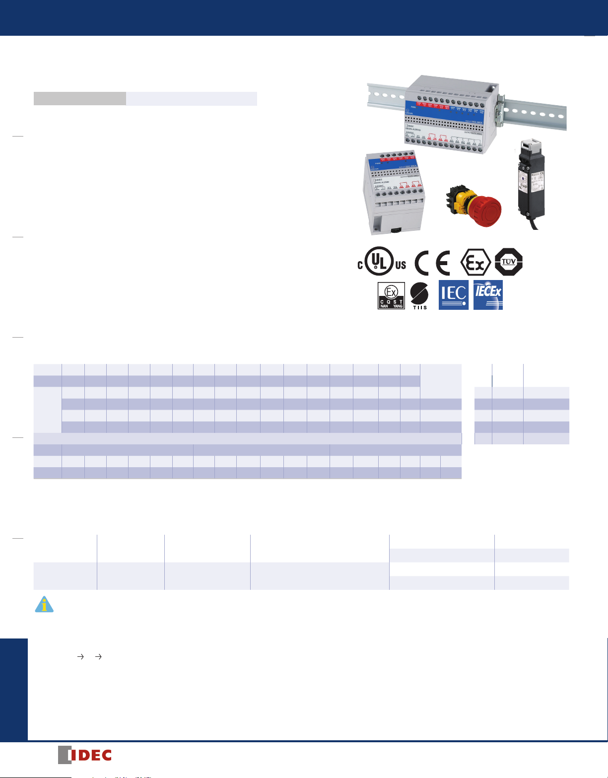
EB3N
EB3N Discrete Input Barrier with Redundant Output
Build a safety system in an explosive atmosphere.
Key features:
Safety Performance Performance level e Category 4
OI TouchscreensPLCsAutomation SoftwarePower SuppliesSensorsCommunicationBarriers
• [Exia] II C
• Ensures safety and machine safety in an explosive atmosphere
• Machine safety system can be built in compliance with ISO13849-1 Category 4,
Performance level e.
• Safety input devices applicable in any explosive gas and hazardous areas are
available.
• Available with auxiliary inputs (5 points) used to monitor the operating status of
safety input devices
• Global usage
USA (UL),
Global IEC-Ex,
Europe (ATEX),
Japan (TIIS),
China (CQST)
Machine safety: TÜV Rheinland
• No grounding required
Barriers
Entity Barrier Parameters
Ta= 60°C, Um= 250V, (Um=125V UL only), Uo=13.2V, Io= 14.2mA, Po= 46.9mW at each channel
Pn-Nn Io=227.2mA, Po= 750mW at max 16 channels Pn-Nn
Io(mA) 14.2 28.4 42.6 56.8 71.0 85.2 99.4 113.6 127.8 142.0 156.2 170.4 184.6 198.8 213.0 227.2
Po(mW) 46.9 93.8 140.6 187.5 234.3 281.2 328.1 375.9 421.8 468.7 515.5 562.4 609.2 656.1 702.9 750
0.67 0.65 0.63 0.61 0.59 0.57 0.55 0.53 0.51 0.49 0.47 0.44 0.42 0.39 - - 1.0 Uo 13.2V 13.2V
0.79 0.77 0.76 0.75 0.73 0.72 0.70 0.69 0.67 0.66 0.64 0.62 0.61 0.59 0.57 0.55 0.5 Io 14.2mA 227.2mA
Co(μF)
0.94 0.94 0.94 0.94 0.94 0.94 0.94 0.93 0.92 0.91 0.90 0.88 0.87 0.86 0.85 0.84 0.2 Po 46.9mW 750mW
0.94 0.94 0.94 0.94 0.94 0.94 0.94 0.94 0.94 0.94 0.94 0.94 0.94 0.94 0.94 0.94 0.1 Co 0.47μF 0.28μF
Note 1 Added to above table, the next values combined Lo and Co are allowable; Lo 87.5mH 0.56mH
Io(mA) 14.2 28.4 227.2
Lo(mH) 175* 87.5 30.0 2.5 0.55 0.25 43.5* 21.5 20.0 3.5 0.43 0.25 0.68* 0.34 0.68 0.6 0.22 0.13
0.90* 0.45 0.33 0.54 0.77 0.90 0.90* 0.45 0.30 0.48 0.80 0.90 0.90* 0.45 0.45 0.49 0.80 0.90
Co(µF)
Note 2 The intrinsic safe apparatus and wirings shall be accordance to following formulas; for example: Ui ≥ Uo Ii ≥ Io Pi ≥ Po Ci+Cc ≤ Co Li+Lc ≤ Lo
*: Therefore, the values are allowable only at Li ≤ 1%Lo and Ci ≤ 1%Co of the intrinsic safe apparatus. (In the case of 50% of Co and Lo parameters are applicable,the maximum
capacitance allowed shall not be more than Co = 1 µF for IIB and Co= 600 nF for IIC.)
Discrete Input Barrier with Redundant Output
2 2NO Without Without
2 2NO 5 (1 common) 5NO (1 common)
1. A maximum of ve monitor contacts from safety input devices can be connected to the auxiliary input terminals. In addition, non-safety input devices can also be connected to the auxiliary input
terminals.
2. On auto reset (auto start) models, when the safety condition is met (two safety inputs are both on), safety outputs are turned on automatically.
Connect the reset (start) input terminals Y1 and Y2 together except for the following cases:
When connecting a contactor or force guided relay to the safety output of the EB3N, connect the NC contacts of the contactor or force guided relay to the reset (start) input terminals Y1 and Y2 of the
EB3N for use as a backcheck input signal.
3. On manual reset (manual start) models, while the safety condition is met (two safety inputs are both on), safety outputs are turned on at the falling edge of the reset switch (start switch) signal
(OFF
ON OFF) (start off check).
Manual reset (manual start) models have a monitoring function of reset switch contacts (detection of welded contacts). Use NO contacts of a momentary switch for the reset (start) input.
When connecting a contactor or force guided relay to the safety output of the EB3N, connect the NC contacts of the contactor or force guided relay to the reset (start) input terminals Y1 and Y2 of the
EB3N for use as a backcheck input signal.
Combined
Lo(mH)
Auto reset (Auto start) EB3N-A2ND
Manual reset (Manual start) EB3N-M2ND
Auto reset (Auto start) EB3N-A2R5D
Manual reset (Manual start) EB3N-M2R5D
TIISI only
Ta=60°C, Um=250V
1 ch
Seperate
5 ch
Common
254
1705151127
Page 2
Barriers
EB3N
Selection Guide
1. Selecting the reset (start) function
Auto reset (auto start): Select this model when connecting safety control devices, such as safety relay modules or safety controllers, to the EB3N safety
outputs to set up a safety system, using the reset (start) function of the safety control device.
Select this model when connecting contactors or force guided relays to the EB3N safety outputs to set up a safety system, and a
risk assessment on the entire system has not found any safety problem in using auto reset (auto start).
Manual reset (manual start): Select this model when connecting contactors or force guided relays to the EB3N safety outputs to set up a safety system, and a
risk assessment on the entire system has found that manual reset (manual start) is necessary.
2. Selecting the auxiliary outputs
Without auxiliary outputs: Select this model when the operating status of safety input devices are not monitored.
With auxiliary outputs: Select this model when the operating status of safety input devices are monitored or when non-safety input devices are also con-
nected.
Specications
EB3N General Specications
Rated Power Voltage 24V DC
Power Voltage Range 20.4 to 26.4V DC
Operating Temperature
Operating Humidity
Power
Consumption
Safety
Output
Auxiliary
Output
Mounting DIN rail or panel mounting
*: Channel Numbers: 1 to 5
Without auxiliary output 5.5W maximum
With auxiliary output 7.0W maximum
Contacts 13-14, 23-24 2NO
Rated Load
Response
(rated voltage)
Contacts A* - C1 5NO/1 common
Rated Load Resistive
Response
(rated voltage)
Resistive 30V DC, 1A
Inductive DC-13, 24V, 1A
Turn on 100 ms maximum
Turn off 20 ms maximum
Turn on 15 ms maximum
Turn off 10 ms maximum
–20 to +60°C (no freezing)
UL: –20 to +40°C
(no freezing)
45 to 85% RH
(no condensation)
24V DC, 3A,
common terminal 5A max.
EB3N Safety Specications
Category 4
Performance Level (PL) e
Mean Time to Dangerous Failure (MTTFd) 100 years
Diagnostic Range 99% minimum
Calculation conditions for MTTFd
t
: Mean operation cycle = 1 hour
cycle
: Mean operation hours per day = 24 hours
h
op
d
: Mean operation days per year = 365 days
op
Note: When t
is shorter than 1 hour, MTTFd will decrease
cycle
OI Touchscreens PLCs Automation Software Power Supplies Sensors Communication Barriers
EB3N Certications
Certication
Organization
UL
PTB (IEC-Ex) [Exia] II C, [Exia D] IEC Ex PTB 10.0015
PTB (ATEX)
TIIS
CQST [Exia] IIC CNEx11.0038
1705151127
Ratings Certication Number
Class I, Zone 0, [AExia] II C
Class I, II, III, Div. 1, Groups A, B, C, D, E, F and G
II (1) G [Exia] II C
II (1) D [Exia D]
Discrete Input Barriers with Redundant Output [Exia] II C
Switch (EB9Z-A) Exia II CT6
Switch (EB9Z-A1) Exia II BT6
E234997
PTB 09 ATEX 2046
TC18753
TC15758
TC15961
255
Page 3

EB3N
65.0
75.0
110.5
77.5
75.0
2-M4 tapped or
2-ø4.5 drilled holes
1:1 connection with a safety input device, compliant with Category
Connection with multiple safety input devices, capable of monitoring up to 5 contact operations, compliant with Category
For monitoring operating statuses of safety input devices located in a non-hazardous area
Barriers
Dimensions (mm)
EB3N-A2ND
EB3N-M2ND
OI TouchscreensPLCsAutomation SoftwarePower SuppliesSensorsCommunicationBarriers
Mounting Hole Layout
EB3N-A2ND
EB3N-M2ND
65
51
EB3N System Conguration Examples
Hazardous Area Non-hazardous Area
Safety Input Device
Safety Input Device
EB3N-A2R5D
EB3N-M2R5D
EB3N-A2R5D
EB3N-M2R5D
2-M4 tapped or
2-ø4.5 drilled holes
97
EB3N-A2ND Safety Control Device
EB3N-M2ND Safety Contactor
Barrier Safety Output
Barrier Safety Output
Backcheck Input
Reset (Start) Input
65
Reset (Start) Input
Terminal Functions
24V DC Power
Y1-Y2 Reset input (Start input)
11-12 Safety input 1
21-22 Safety input 2
N1, N2 Signal ground
P*-N3 Auxiliary input
13-14 Safety output 1
23-24 Safety output 2
A*-C1 Auxiliary output
*: 1 to 5
4
Safety Output
Backcheck Input
Safety Contactor
• A safety relay module or safety controller is
used to set up a safety circuit, using the reset
(start) function of the safety relay module or
safety controller.
• The reset (start) function is used to set up a
safety circuit, without using a safety relay
module or safety controller.
3
Hazardous Area Non-hazardous Area
Safety Input Devices
Connected in Series
…
Monitor
Safety Input Devices
Connected in Series
…
Monitor
EB3N-A2R5D
EB3N-M2R5D
Barrier Safety Output
Auxiliary Output
(Monitor Output)
Barrier Safety Output
Backcheck Input
Reset (Start) Input
Auxiliary Output
(Monitor Output)
Safety Control Device
PLC
Safety Contactor
PLC
Safety Output
Backcheck Input
Reset (Start) Input
Safety Contactor
• A safety relay module or safety controller is
used to set up a safety circuit, using the reset
(start) function of the safety relay module or
safety controller.
• The manual reset (manual start) function of
the EB3N is used to set up a safety circuit,
without using a safety control device.
256
1705151127
Page 4

Barriers
Installing a reset switch in a hazardous area, using auxiliary input and output
EB3N
Hazardous Area Non-hazardous Area
Safety Input Devices
…
Reset (Start) Switch
Other Input Device
Safety Input Devices
Reset (Start) Switch
Other Input Device
EB3N-A2R5D
EB3N-M2R5D
Barrier Safety Output
Reset (Start) Output
Other Output
Barrier Safety Output
Backcheck Input
Reset (Start) Input
Other Output
Safety Control Device
Safety Contactor
Safety Input Devices Connectable to Safety Input Terminals (Examples)
Emergency stop switch: (Non-illuminated) XW1E-BV402M-R, XN4E-BL412MRH
Safety switch: HS6B-02B05, HS1B-02R
Notes for Operation
1. Do not disassemble, repair, or modify the EB3N discrete input barrier with
redundant output, otherwise the safety characteristics may be impaired.
2. Use the EB3N within its specication values.
3. The EB3N can be mounted in any direction.
4. Mount the EB3N on a 35-mm-wide DIN rail or directly on a panel surface using screws. When mounting on a DIN rail, push in the clamp and use end clips
to secure the EB3N. When mounting on a panel surface, tighten the screws
rmly.
5. Excessive noise may cause malfunction or damage to the EB3N. When the
internal voltage limiting circuit (thyristor) has shut down the power due to
noise, remove the cause of the noise before powering up again.
6. The internal power circuit contains an electronic fuse to suppress overcurrents. When the electronic fuse has tripped, shut down the power, remove the
cause of the overcurrent before powering up again.
7. Use crimping terminals with insulation sheath for wiring. Tighten the terminal
screws, including unused terminal screws, to a recommended tightening
torque of 0.6 to N·m using a screwdriver of ø5.5 mm in diameter.
8. Before inspecting or replacing the EB3N, turn off the power.
OI Touchscreens PLCs Automation Software Power Supplies Sensors Communication Barriers
Safety Output
Backcheck Input
PLC
PLC
Safety Contactor
Instructions
Notes for Machine Safety
1. Operate the safety input device to check the EB3N functionality everyday.
2. For safety input devices, such as safety switches or emergency stop switches,
connected to the EB3N, use safety standard-compliant devices with direct
opening action and 2NC contacts.
3. Do not use the auxiliary input as a safety input.
4. For safety control devices connected with the EB3N, use machine safety
standard-compliant devices with a disparity detection function.
5. Use safety inputs and safety outputs in a circuit conguration compliant with
safety requirements.
6. To calculate the safety distance, take into consideration the response time
of all devices comprising the system, such as the EB3N and safety devices
connected to the EB3N.
7. Separate the input and output wiring from power lines and motor lines.
8. When using multiple EB3N discrete input barriers with redundant output, do
not connect one switch to more than one EB3N. Use separate switches for
each EB3N.
9. To ensure EMC, use shielded cables for safety inputs and auxiliary inputs.
Connect the shield to the FG of the control panel on which the EB3N is
mounted.
10. For protection against overcurrents, connect an IEC60127-2-compliant 2A
fast-blow fuse (5 × 20 mm).
11. Evaluate the ISO 13849-1 category and performance level in consideration of
the entire system.
1705151127
257
Page 5

EB3N
Barriers
Safety Notes
1. Install the EB3N in an enclosure capable of protecting against mechanical
shocks at a hazardous location in accordance with intrinsic safety ratings and
parameters.
2. Install and wire the EB3N so that the EB3N is not subject to electromagnetic
OI TouchscreensPLCsAutomation SoftwarePower SuppliesSensorsCommunicationBarriers
and electrostatic induction and does not contact with other circuits.
For example, keep a minimum spacing of 50 mm between intrinsically safe
and non-intrinsically safe circuits, or provide a metallic separating board
between the intrinsically safe circuit and non-intrinsically safe circuit. When
providing a metallic separating board, make sure that the board ts closely to
the enclosure (top, bottom, and both sides). Allowable clearance between the
board and the enclosure is 1.5 mm at the maximum.
When a motor circuit or high-voltage circuit is installed nearby, keep a wider
spacing than 50 mm between intrinsically safe and non-intrinsically safe
circuits.
3. Keep a minimum spacing of 3 mm between the terminal or relay terminal
block of the intrinsically safe circuit and the grounded metal parts of the
metal enclosure.
4. Connect the terminals so that IP20 is ensured.
5. To prevent disengaged wires from contacting with other intrinsically safe
circuits, bind together the end of wires.
6. Make sure that the voltage of the power supply for the devices connected to
the non-intrinsically safe circuit or the internal voltage of such devices does
not exceed 250V AC/DC 50/60 Hz (UL rating: 125V AC 50/60 Hz) or 250V DC
(UL rating: 200V DC) under any normal and abnormal conditions.
7. Make sure that the wiring of intrinsically safe circuits does not contact with
other circuits or is not subject to electromagnetic and electrostatic inductions,
otherwise protection from hazards is not ensured.
8. When identifying intrinsically safe circuits by color, use light blue terminal
blocks and cables.
9. When wiring the intrinsically safe circuit, determine the distance to satisfy
the wiring parameters shown below.
a) Wiring capacitance Cw ≤ Co – Ci
Co: Intrinsically safe circuit allowable capacitance
Ci: Internal capacitance of switches
b) Wiring inductance Lw ≤ Lo – Li
Lo: Intrinsically safe circuit allowable inductance
Li: Internal inductance of switches
c) Wiring resistance ≤ Rw
Rw: Allowable wiring resistance
Switches in the Hazardous Area
1. A switch contains the switch contact, enclosure, and internal wiring. A switch
contact refers to an ordinary switching device which consists of contacts only.
2. When the switch has internal wiring or lead wire, make sure that the values
of internal capacitance (Ci) and inductance (Li) are within the certied values.
3. Enclose the bare live part of the switch contact in an enclosure of IP20 or
higher protection.
258
1705151127
 Loading...