

EB3L
Barriers
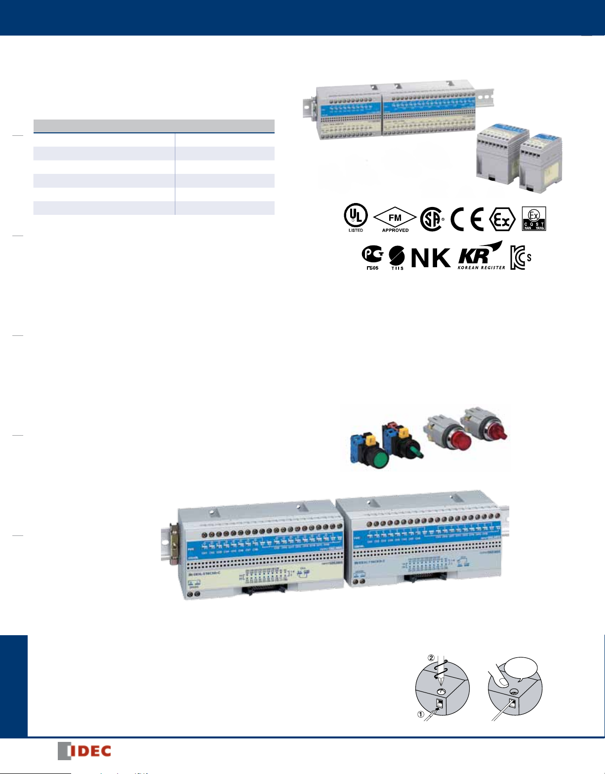
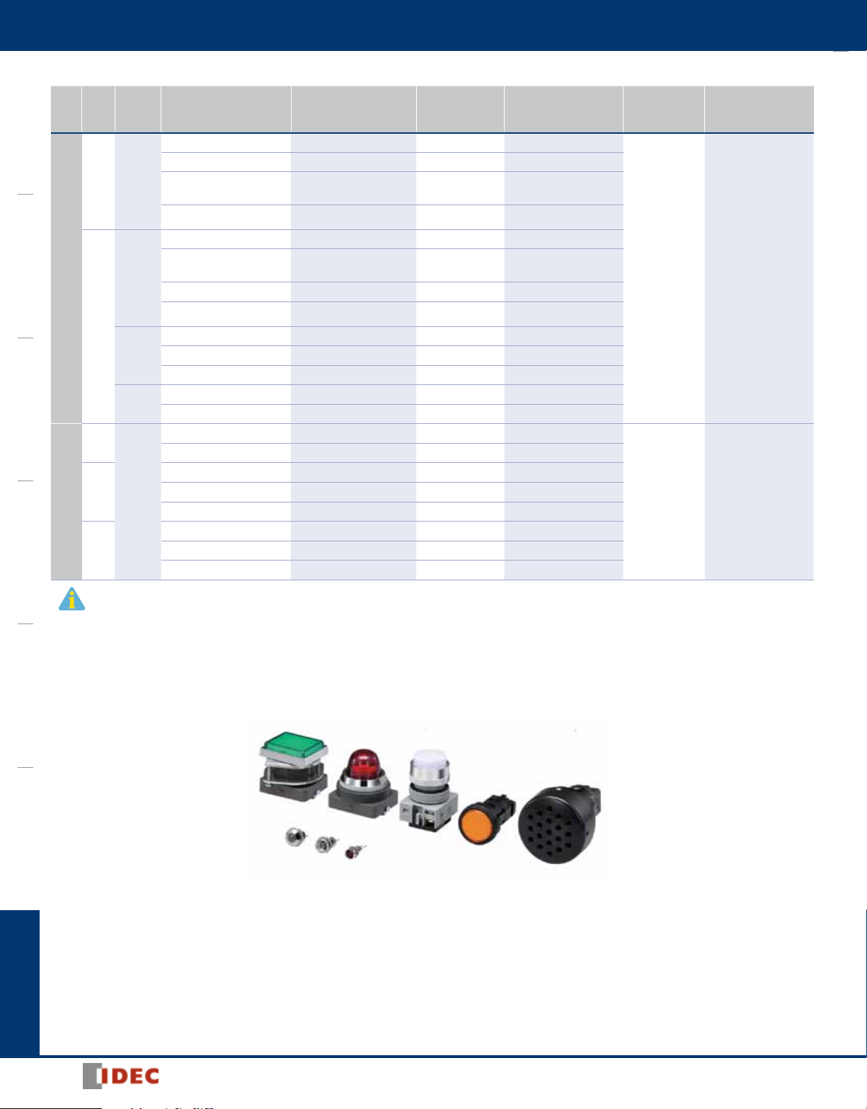
EB3L Discrete Output Barriers
126 types of pilot lights and buzzers can be connected. Illuminated pushbuttons and
illuminated selector switches can be connected by combining with the EB3C discrete
input barrier.Nogrounding required.
Key features:
OI TouchscreensPLCsAutomation SoftwarePower SuppliesSensorsCommunicationBarriers
Explosion protection
Discrete Output Barrier [Exia] II C
Pilot Light (separate wiring) Exia II CT6
Pilot Light (common wiring) Exia II CT4
Illuminated Pushbutton Exia II CT4
Illuminated Selector Switch Exia II CT4
Buzzer (separate wiring) Exia II CT6
• IEC60079 compliant
• Compact and lightweight (46% footprint and 36% weight com pared to IDEC’s
10-circuit IBPL)
• 8- and 16-channel types are available in common wiring types, ideal for connection
to PLCs. 16-circuit types are also available with a connector.
• Universal AC power voltage (100 to 240V AC or 24V DC power
[UL rating: 100 ~ 120V AC])
• No grounding required
• IDEC’s original spring-up terminal minimizes wiring time.
• Installation, 35-mm-wide DIN rail mounting or direct screw mounting
• ø6, ø8, ø10, ø22 and ø30 pilot lights available
• Illuminated pushbuttons and illuminated selector switches can be connected by
combining with the EB3C discrete input barrier.
Illumination colors: Amber, blue, green, red, white, and yellow
(pushlock turn reset type: red only)
• Continuous and intermittent sound types are available for buzz ers (ø30).
• Global usage
USA: UL/FM
Canada: CSA
Europe: CE marking, ATEX
China: CQST
Russia: GOST-R
Japan: TIIS
Korea: KOSHA
• Ship class: NK (Japan), KR (Korea)
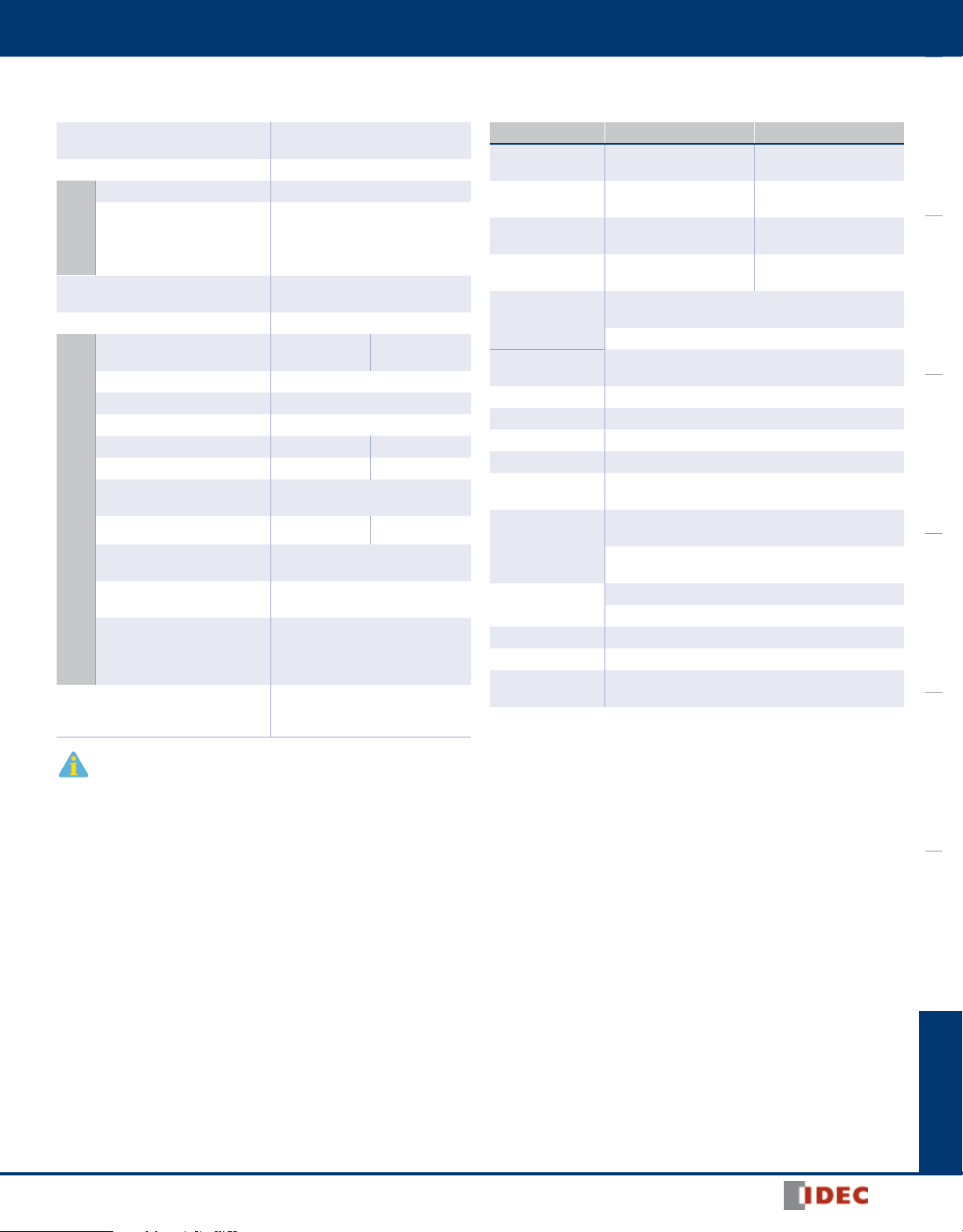
Illuminated Pushbutton/Selector Switches
Illuminated pushbutton/selector switches can be used
with the combination of EB3C and EB3L.
234
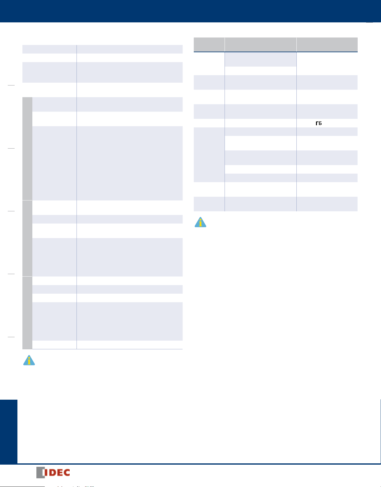
Common Wiring for PLC Inputs
EB3L Discrete Output Barrier
8- and 16-circuit types are available in common wiring
types, ideal for connection to PLCs (DC voltage only).
Connector Type
MIL connecotr on the non-hazardous side
• Easy connection to PLCs
• Wiring is cut by 90% (compared with IDEC’s 16-circuit EB3C)
• Various 20-pin MIL connectors can be connected.
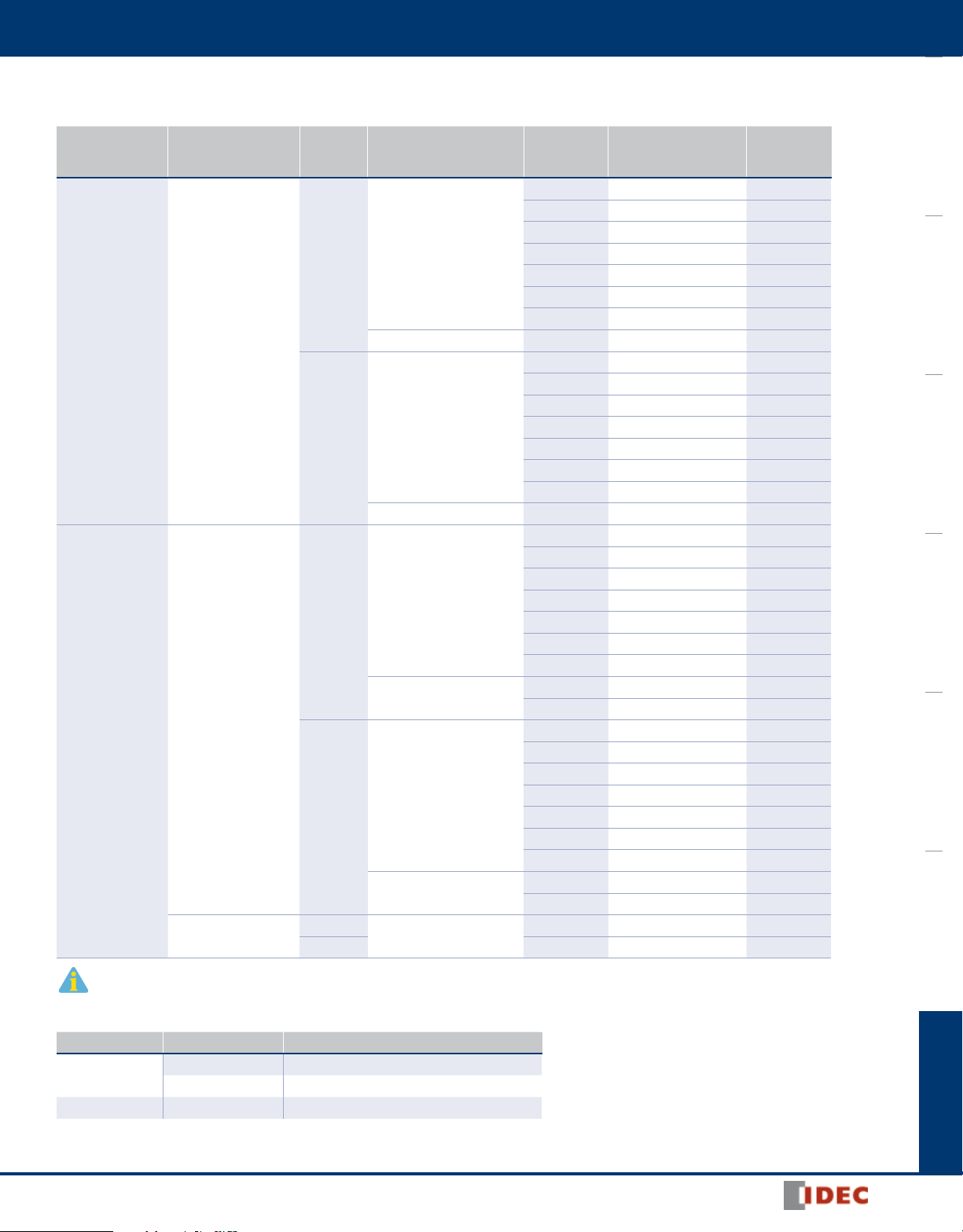
EB3C Discrete Input Barrier
Spring-up Fingersafe Terminals Reduce
Wiring Time
Finger-safe
www.IDEC.com
Barriers
EB3L
Explosion-Protection and Electrical
Explosion Protection
Degree of Protection IP20 (IEC60529)
Discrete Output Barrier Safe indoor place (non-hazardous area)
Pilot Light, Illuminated Switch,
Location
Buzzer (TIIS approval only)
Installation
Non-intrinsically Safe Circuit
Maximum Voltage (Um)
Operation Input ON, Output ON (1:1)
Wiring Method
Rated Operating Voltage 12V DC
Rated Operating Current 10 mA DC ±10%
Maximum Output Voltage (Uo) 13.2V DC ±10%
Maximum Output Current (lo) 14.2 mA 227.2 mA
Maximum Output Power (Po) 46.9 mW 750 mW
Maximum External
Capacitance (Co)
Maximum External Inductance (Lo)
Allowable Wiring Resistance (Rw)
Intrinsically Safe Circuits (Output)
Maximum Channels per
Common Line
Voltage and Current when
Connecting Control Units
Non-intrinsically Safe Circuits
(Signal Input)
1
Intrinsic safety type
(IEC compliant) [Exia] II C
For zone 0, 1, 2 hazardous areas
250V AC 50/60Hz, 250V DC
UL value: 125V AC
1-channel
Separate Wiring
900 (740) nF
1
175 (125) mH 0.68 (0.68) mH
200/(N+1)Ω
(N = number of common channels)
16
Pilot light: 3.5V, 8.5 mA
Miniature pilot light: 2V, 10 mA
Illuminated switch: 3.5V, 8.5 mA
Buzzer: 6.5V, 5.5 mA
Rated voltage: 24V DC
Rated current: 5 mA
(connector type: 4 mA)
Specifications
16-channel
Common Wiring
General
Power Voltage Type AC Power DC Power
Rated Power Voltage
Allowable Voltage
Range
Rated Frequency
Inrush Current
Dielectric Strength
(1 minute, 1 mA)
Operating Temperature
Storage Temperature –20 to +60°C (no freezing)
Operating Humidity 45 to 85% RH (no condensation)
Atmosphere 800 to 1100 hPa
Pollution Degree 2 (IEC60664)
Insulation Resistance
Vibration Resistance
(damage limits)
Shock Resistance
(damage limits)
Terminal Style M3 screw terminal
Mounting 35-mm-wide DIN rail or panel mounting (M4 screw)
Power Consumption
(approx.)
100 to 240V AC
(UL rating: 100 ~ 120V AC)
85 to 264V AC
(UL rating: 85 ~ 125V AC)
50/60 Hz (allowable range: 47
to 63 Hz)
10A (100V AC)
20A (200V AC)
Between intrinsically safe circuit and non-intrinsically safe
circuit: 1500V AC
Between AC power and signal input: 1500V AC
–20 to +60°C (no freezing)
10 MΩ minimum (500V DC megger, between the same poles
as the dielectric strength)
Panel mounting: 10 to 55 Hz, amplitude 0.75 mm
(2 hours each on X, Y, Z)
DIN rail mounting: 10 to 55 Hz, amplitude 0.35 mm
(2 hours each on X, Y, Z)
Panel mounting: 500 m/s
DIN rail mounting: 300 m/s2 (3 times each on X, Y, Z)
8.8 VA (EB3L-S10SA at 200V AC)
5.2 W (EB3L-S16CSD at 24V DC)
24V DC
21.6 to 26.4V DC
10A
2
(3 times each on X, Y, Z)
OI Touchscreens PLCs Automation Software Power Supplies Sensors Communication Barriers
—
1. Values in ( ) are those approved by TIIS (Technology Institution of Industrial Safety, Japan).
800-262-IDEC (4332) • USA & Canada
235
EB3L
Barriers
General Specifications of Pilot Light, Illuminated Pushbutton,
Illuminated Selector Switch, and Buzzer
Operating Temperature –20 to +60°C (no freezing)
Operating Humidity 45 to 85% RH (no condensation)
OI TouchscreensPLCsAutomation SoftwarePower SuppliesSensorsCommunicationBarriers
Dielectric Strength
(1 mA, 1 minute)
Insulation Resistance
Degree of Protection
Lens/Illumination
Color
Intrinsic Safety
Ratings and
Parameters
Pilot Light and Miniature Pilot Light
Degree of Protection
Illumination Color Amber, blue, green, red, white, yellow
Contact
Voltage/Current
Intrinsic Safety
Illuminated Switch
Ratings and
Parameters
Degree of Protection IP20 (IEC60529) (except for terminals)
Sound Volume 75 dB minimum (at 1 m)
Sound Source Piezoelectric oscillator (continuous or intermittent)
Intrinsic Safety
Buzzer
Ratings and
Parameters
Weight 100g
EB3P: 1000V AC
IPL1: 500V AC
(between intrinsically safe circuit and dead parts)
10 MΩ minimum (500V DC megger, between the same
poles as the dielectric strength)
IP65 (IEC60529) (except for terminals)
EB3P-LU/IPL1: IP40
Pilot light: Amber, blue, green, red, white, yellow
Miniature pilot light: Amber, green, red, white, yellow
1-channel Separate Wiring
Maximum input voltage (Ui): 13.2V
Maximum input current (Ii): 14.2 mA
Maximum input power (Pi): 46.9 mW
Internal capacitance (Ci): ≤ 2 nF
Internal inductance (Li): ≤ 5 µH
16-channel Common Wiring
Maximum input voltage (Ui): 13.2V
Maximum input current (Ii): 227.2 mA
Maximum input power (Pi): 750 mW
Internal capacitance (Ci): ≤ 32 nF
Internal inductance (Li): ≤ 80 µH
IP65 (IEC60529) (except for terminals)
EB3P-LSAW**: IP54
12V DC ±10%, 10 mA ±20%
(when connecting to the EB3C)
16-channel Common Wiring
Maximum input voltage (Ui): 13.2V
Maximum input current (Ii): 227.2 mA
Maximum input power (Pi): 750 mW
Internal capacitance (Ci): ≤ 32 nF
Internal inductance (Li): ≤ 80 µH
1-channel Separate Wiring
Maximum input voltage (Ui): 13.2V
Maximum input current (Ii): 14.2 mA
Maximum input power (Pi): 46.9 mW
Internal capacitance (Ci): ≤ 260 nF
Internal inductance (Li): ≤ 100 mH
Certification Number
Certification
Organization
FM
CSA
NEMKO
CQST
GOST-R [Exia] II C POCC JP.
TIIS
NK
KOSHA
Note: Illuminated switches, pilot lights, and miniature pilot lights are certified by TIIS and NK
only. Other certification organizations, such as UL, regard these units as simple apparatus,
and require no certification.
Explosion Protection Certification No.
Class I, II, III Div. 1
Group A, B, C, D, E, F, G
Class I, Zone 0 AEx [ia] II C
Class I Div. 1
Group A, B, C, D
Discrete output barrier: [Exia] II C
Buzzer: Exia II CT6
Discrete output barrier: [Exia] II C
Buzzer: Exia II CT6
Discrete output barrier: [Exia] II C TC16355
Pilot light/miniature pilot light:
(separate wiring): Exia II CT6
Pilot light/miniature pilot light:
(common wiring): Exia II CT4
Illuminated switch: Exia II CT4 TC16362
Buzzer: Exia II CT6 TC16363
Discrete output barrier: [Exia] II C
Buzzer: Exia II CT6
Discrete output barrier: [Exia] II C
Buzzer: Exia II CT6
3015417
LR 21451
Nemko 02ATEX279
Nemko 03ATEX1628X
CNEX 10.2445
TC16361
TC16360
Type Test No. 02T606
Type Test No. 04T605
KOB17821-EL001
KOB17821-EL002
05.B03253
Note: Connect buzzers in separate wiring. Buzzers cannot be used in com mon wiring.
236
www.IDEC.com
Barriers
EB3L
Discrete Output Barriers
Power Voltage
100 to 240V AC
(UL rating: 100 ~
120V AC)
24V DC
*Note: These models are NOT Listed by UL
Non-intrinsically
Screw Terminal
Screw Terminal
Connector
Connection to
Safe Circuit
Part Numbers
Input Input Wiring Method
Separate/Common
Source
Sink
Source
Sink
Source
Sink 16 EB3L-S16CKD-C* 350
Wiring Compatible
Common Wiring Only 8 EB3L-S08CSA 260
Separate/Common
Wiring Compatible
Common Wiring Only 8 EB3L-S08CKA 260
Separate/Common
Wiring Compatible
Common Wiring Only
Separate/Common
Wiring Compatible
Common Wiring Only
Common Wiring Only
Number of
Channels
1 EB3L-S01SA 150
2 EB3L-S02SA 180
3 EB3L-S03SA 190
5 EB3L-S05SA 250
6 EB3L-S06SA 260
8 EB3L-S08SA 330
10 EB3L-S10SA 360
1 EB3L-S01KA 150
2 EB3L-S02KA 180
3 EB3L-S03KA 190
5 EB3L-S05KA 250
6 EB3L-S06KA 260
8 EB3L-S08KA 330
10 EB3L-S10KA 360
1 EB3L-S01SD 130
2 EB3L-S02SD 160
3 EB3L-S03SD 170
5 EB3L-S05SD 240
6 EB3L-S06SD 250
8 EB3L-S08SD 310
10 EB3L-S10SD 250
8 EB3L-S08CSD 340
16 EB3L-S16CSD 350
1 EB3L-S01KD 130
2 EB3L-S02KD 160
3 EB3L-S03KD 170
5 EB3L-S05KD 240
6 EB3L-S06KD 250
8 EB3L-S08KD 310
10 EB3L-S10KD 340
8 EB3L-S08CKD* 250
16 EB3L-S16CKD* 350
16 EB3L-S16CSD-C 350
Part Number Weight (g)
OI Touchscreens PLCs Automation Software Power Supplies Sensors Communication Barriers
Accessories
Name Part Number Description
DIN Rail
End Clip BNL6 Medium DIN rail end clip
BNDN1000 Aluminum (1m long, 10.5mm high)
BAP1000 Steel (1m long, 7.5mm high)
800-262-IDEC (4332) • USA & Canada
237
EB3L
Barriers
Pilot Lights, Illuminated Pushbuttons, Illuminated Selector Switches, and Buzzers
TW
HW
LW
UP
1
Dome — — EB3P-LAN1-*
Square — — EB3P-LUN3B-*
Rectangular
w/Metal Bezel
Dome w/Diecast Sleeve — — EB3P-LAD1-*
Flush — — EB3P-LAW1-*
Flush
(Marking Type)
Dome — — EB3P-LAW2-*
Square Flush (Marking Type) — — EB3P-LUW1B-*
Round Flush — — EB3P-LHW1-*
Dome — — EB3P-LHW2-*
Square Flush — — EB3P-LHW4-*
Round — — EB3P-LLW1-*
Square — — EB3P-LLW2-*
Extended — — IPL1-18-*
Dome — — IPL1-19-*
Flush — — IPL1-87-*
Extended — — IPL1-88-*
Dome — — IPL1-89-*
Flush — — IPL1-67-*
Extended — — IPL1-68-*
Dome — — IPL1-69-*
Shape Operation Mode Contact Ordering Number
— — EB3P-LUN4-*
— — EB3P-LAW1B-*
Unit Size Series
OI TouchscreensPLCsAutomation SoftwarePower SuppliesSensorsCommunicationBarriers
Pilot Light
Miniature Pilot Light
ø30 N
ø22
ø10
ø8
ø6
1. Codes N, TW, HW, LW, and UP are the series names of IDEC’s control units.
2. Specify a color code in place of *.
3. Illuminated selector switches have a knob operator.
4. Above parts are recommended for EB3L barriers. However, none of these parts are UL recognized.
Lens Color/
Illumination
Color Code*
A: Amber
G: Green
R: Red
S: Blue
W: White
Y: Yellow
A: Amber
G: Green
R: Red
W: White
Y: Yellow
Operation
—
—
238
www.IDEC.com

Barriers
EB3L
Pilot Lights, Illuminated Pushbuttons, Illuminated Selector Switches, and Buzzers, con’t
Unit Size Series
ø30 N
Illuminated Pushbutton
ø22
ø30 N Round
3
ø22
Illuminated Selector Switch
ø30 — —
Buzzer
1. Codes N, TW, HW, LW, and UP are the series names of IDEC’s control units.
2. Specify a color code in place of *.
3. Illuminated selector switches have a knob operator.
4. Above parts are recommended for EB3L barriers. However, none of these parts are UL recognized.
1
Extended
Mushroom Pushlock Turn Reset 1NO-1NC EB3P-LBAVN311-R Red only
TW
HW Round
LW
TW Round
HW Round
LW Round 2-position DPDT EB3P-LSL1W2C2-* Maintained
Extended
Mushroom Pushlock Turn Reset 1NO-1NC EB3P-LBAVW411-R Red only
Round
Square
Shape Operation Mode Contact Ordering Number
Momentary 1NO-1NC EB3P-LBAN211-*
Maintained 1NO-1NC EB3P-LBAON211-*
Momentary 1NO-1NC EB3P-LBAW211-*
Maintained 1NO-1NC EB3P-LBAOW211-*
Momentary 1NO EB3P-LBH1W110-*
Maintained 1NO EB3P-LBHA1W110-*
Momentary DPDT EB3P-LBL1W1C2-*
Maintained DPDT EB3P-LBLA1W1C2-*
Momentary DPDT EB3P-LBL2W1C2-*
Maintained DPDT EB3P-LBLA2W1C2-*
2-position 1NO-1NC EB3P-LSAN211-* Maintained
3-position 2NO EB3P-LSAN320-* Maintained
2-position 1NO-1NC EB3P-LSAW211-* Maintained
2-position, return from right 1NO-1NC EB3P-LSAW2111-* Spring return from right
3-position 2NO EB3P-LSAW320-* Maintained
3-position,
return from right
3-position,
return from left
3-position,
2-way return
2-position 1NO-1NC EB3P-LSHW211-* Maintained
3-position 2NO EB3P-LSHW320-* Maintained
Continuous sound — EB3P-ZUN12C —
Intermittent sound — EB3P-ZUN12F —
2NO EB3P-LSAW3120-* Spring return from right
2NO EB3P-LSAW3220-* Spring return from left
2NO EB3P-LSAW3320-* 2-way spring return
2
Lens Color/
Illumination
Color Code*
A: Amber
G: Green
R: Red
S: Blue
W: White
Y: Yellow
A: Amber
G: Green
R: Red
S: Blue
W: White
Y: Yellow
A: Amber
G: Green
R: Red
S: Blue
W: White
Y: Yellow
OI Touchscreens PLCs Automation Software Power Supplies Sensors Communication Barriers
Operation
—
Accessory
Name Ordering Number Package Quantity Remarks
LED Lamp EB9Z-LDS1-* 1 Specify a color code in place of * in the Ordering No. A: amber, G: green, R: red, S: blue, W: white, Y: yellow
Above part is recommended for EB3L barriers. However, this part is not UL recognized.
800-262-IDEC (4332) • USA & Canada
239

EB3L
–
P1 N1 P2 N2 P3 N3
S1NLC1S2C2S3C3
–
–
~
Green
YellowYellowYellow
–+–+–+
–+–+–
+
–
P1 P16 N1 N2
S1 S16 C1 C2
–
Green
YellowYellow
–+
~
~
~
–
P1 N1 P2 N2 P3 N3
S1 C1 S2 C2 S3 C3
–
Green
YellowYellowYellow
–+
~
~
~
Safe Area
(Non-hazardous Area)
Hazardous Area
65
10101010
65
28 51 97 97
65
10
6
77.5
75
61
42
171.5
110.565 77.5
4
(4)
EB3L–S02
EB3L–S03
EB3L–S06
EB3L–S05
EB3L–S08C
EB3L–S16C
EB3L–S10
EB3L–S08
EB3L–S01
2-M4 tapped or
2-ø4.5 mounting holes
4-M4 tapped or
4-ø4.5 mounting holes
2-M4 tapped or
2-ø4.5 mounting holes
2-M4 tapped or
2-ø4.5 mounting
holes
ø6 hole
ø4.4
Intrinsic Safety Side:
Light Blue
Non-Intrinsic Safety Side:
Yellow
Mounting Hole Layout (Screw Mounting)
Terminal
83.5
ø6
6
(4)
4- ø4.5 holes
77.5
75
97
171.5
10
10
65
97
65
4-M4 or 4-ø4.5 holes
Mounting Hole Layout
EB3C–T16C -C
Connector
5.4 min.3 max.
6 max.
ø3.2 min.
6 to 8 mm
Solid Wire
Stripping the Wire End
Applicable Crimping Terminal
Barriers
Internal Circuit Block Diagram
AC Power
Source Input
OI TouchscreensPLCsAutomation SoftwarePower SuppliesSensorsCommunicationBarriers
DC Power
Sink Input
Connector Wiring
Source Input
Dimensions (mm)
240
www.IDEC.com

Barriers
ø35
21.5
36
40
23.5
Panel Thickness 0.8 to 7.5
M3 Terminal
Screw
M3 Terminal
Screw
40
36
34×40
52.2
44
29.5
10.5
Panel Thickness 0.8 to 4.5
ø24.8
9
29.8
ø35
40
21.4
ø40
Panel Thickness 0.8 to 7.5
M3.5 Terminal
Screw
M3 Terminal
Screw
40
36
34
Panel Thickness 0.8 to 5.5
23
20
52.2
44
28.5 13
Panel Thickness 1 to 6
30
ø2937ø24
17
34.3
M3.5
Terminal
Screw
Terminal Cover (supplied)
APS-PVL
28.5 13
25
30
ø23.6
ø29
37
M3.5
Terminal
Screw
34.3
Panel Thickness 1 to 6
Terminal Cover (supplied)
APS-PVL
Marking Plate: 22
28.5 13 30
37
16
25
30
M3.5
Terminal
Screw
34.3
Panel Thickness 1 to 6
Terminal Cover (supplied)
APS-PVL
M3.5 Terminal Screw
Gasket
Locking Ring
Flush
X2
X1
Panel Thickness 0.8 to 6
0.5
743.3
Dome Round/Dome
17.5
ø29
Square
29.6
7.2
4.5
Gasket
Locking Ring
Panel Thickness 0.8 to 6
SquareRound
+ Terminal
M10
P1.0
Panel Thickness 0.6 to 4
7
ø12
13.8
9
12
20
5.5
+ Terminal
M10
P1.0
Panel Thickness 0.6 to 4
7
ø12
13.8
9
12.8
20.8
ø9.9
5
+ Terminal
M8
P0.75
Panel Thickness 0.6 to 4
6.1
9
13.8
3
21.8
ø10
11.5
+ Terminal
M8
P0.75
Panel Thickness 0.6 to 4
6.1
ø10
11.5
9
11.5
19.5
4.5
+ Terminal
M8
P0.75
Panel Thickness 0.6 to 4
6.1
ø10
11.5
ø8.1
5
9
11.8
19.8
+ Terminal
M6
P0.75
9.2
ø7.5
2.5
20.3
11.8
7
Panel Thickness 0.6 to 4
4.6
+ Terminal
M6
P0.75
9.2
ø7.5
7
Panel Thickness 0.6 to 4
4.6
10
3.5
18.5
+ Terminal
M6
P0.75
9.2
ø7.5
7
Panel Thickness 0.6 to 4
4.6
11.3
3
ø6
19.8
M3 Terminal Screw
M3.5 Terminal Screw
63
9
23.5
Panel Thickness 0.8 to 7.5
5.5
23
ø35
ø24
ø40
40
M3 Terminal Screw
M3.5 Terminal Screw
63
23.5
Panel Thickness 0.8 to 7.5
5.5
23
ø40
36
40
EB3L
Pilot Lights
EB3P-LAN1
Terminal Cover: APN-PVL
(sold separately)
ø22 EB3P-LAW1
ø22 EB3P-LHW1/EB3P-LHW2/EB3P-LHW4
Terminal cover attached.
ø30 EB3P-LUN4
Terminal Cover: APN-PVL
(sold separately)
ø30 EB3P-LAD
Terminal Cover: APD-PVL
(sold separately)
ø22 EB3P-LAW1B ø22 EB3P-LAW2
ø22 EB3P-LLW1/EB3P-LLW2/EB3P-LLW3
Terminal cover attached.
OI Touchscreens PLCs Automation Software Power Supplies Sensors Communication Barriers
ø30 EB3P-LUN3B
Terminal Cover: APN-PVL
(sold separately)
ø22 EB3P-LUW1B
Miniature Pilot Lights (Terminal cover not available)
ø10 IPL1-18
ø8 IPL1-89
ø10 IPL1-19
ø8 IPL1-67
Illuminated Pushbuttons
ø30 EB3P-LBAN211/LBAON211
Terminal cover: N-VL4 (2 pcs.) (sold separately)
ø10 IPL1-87
ø8 IPL1-68
ø30 EB3P-LBAVN311-R
Terminal cover: N-VL4 (2 pcs.) (sold separately)
ø10 IPL1-88
ø8 IPL1-69
800-262-IDEC (4332) • USA & Canada
241

EB3L
13
19.5
Panel Thickness
1 to 6
37
30
ø29
ø24
ø24
Adjustment
Ring
M3.5 Terminal
Screw
69.4
37
30
13
22.5
ø40
Reset 75°
69.4
Panel Thickness
1 to 6
Adjustment
Ring
M3.5 Terminal
Screw
49.4
25
Panel Thickness 0.8 to 6
ø29
41.4
29.4
13
LOCK
Locking Ring
Lever Stop
M3.5 Terminal
Screw
9
11.7
R18
25.4
23.2
8.5
53.5
Panel Thickness 0.8 to 6
ø25.8
LOCK
M3 Terminal
Screw
9
11.7
R18
25.4
23.2
8.5
53.5
25.8
LOCK
Panel Thickness 0.8 to 6
M3 Terminal
Screw
Panel Thickness 0.8 to 7.5
63 28
9
ø35
ø25
5.5
23
M3.5 Terminal
Screw
M3 Terminal
Screw
ø40
40
9
69.4
13
25
ø
ø29
30
37
Panel Thickness 1 to
6
M3
.5 Terminal
w
M3.5 Terminal
Screw
LOCK
69.4
29.4
41.4
25
ø29
7
21
Panel Thickness
0.8 to 6
ø25.8
9
17.5
11.7
R18
25.4
23.2
8.5
53.5
Panel Thickness
0.8 to 6
LOCK
M3 Terminal
Screw
M3.5 Terminal Screw
41
Panel Thickness
0.8 to 3.5
ø50
35.5
10.6
20.4
Illumination Color
Intrinsic Safety Identification: Light Blue
IDEC Exi
Barriers
ø22 EB3P-LBAW211/LBAOW211
Terminal cover attached.
OI TouchscreensPLCsAutomation SoftwarePower SuppliesSensorsCommunicationBarriers
ø22 EB3P-LBL1W1C2/LBLA1W1C2
Terminal cover: LW-VL2M (sold separately)
Illuminated Selector Switches
ø30 EB3P-LSAN211/EB3P-LSAN320
Terminal cover: N-VL4 (2 pcs.) (sold separately)
ø22 EB3P-LBAVW411-R
Terminal cover attached.
ø22 EB3P-LBL2W1C2/LBLA2W1C2
Terminal cover: LW-VL2M (sold separately)
ø22 EB3P-LSAW***
Terminal cover attached
ø22 EB3P-LBH1W110/LBHA1W110
Terminal cover attached.
All dimensions in mm.
ø22 EB3P-LSHW211/EB3P-LSHW320
Terminal cover attached
Buzzer
ø30 EB3P-ZUN12C/ZUN12F
Terminal cover: AZ-VL5 (sold separately)
ø22 EB3P-LSL1W2C2/EB3P-LSL3W3C2
Terminal cover: LW-VL2M (sold separately)
ø30 EB9Z-LDS1
Illumination color is marked on the terminal.
242
www.IDEC.com

Barriers
Pin Terminals
Positive Terminal
Negative Terminal
Light Blue Marking
Pilot Light
1 kΩ
12V DC
C6
N
6
P6
S5C4S4
S2C1S1
P3N3
P5N5
100 to
240V AC
C2
P8P6P5
P3
S1S2S3S6S7
24V DC
C6
N
6
P6
S5C4S4
S2C1S1
P3N3
P5N5
100 to
240V AC
C2
P
9P8P6P5P3
S1S2S4
S5S6S8C1S
S12
P1
3
S15
P15
S16
P1
6
C4
N
3
24V DC
9
P6
S1
S4
S5
C1
SPS12
S13
S14
S15
P
S16
6
C4
EB3L
Polarity Identification
Pilot Lights/Illuminated Pushbuttons/Illuminated Selector Switches
Positive terminal: X1
Negative terminal: X2
Miniature Pilot Lights
Positive terminal: Long pin terminal
Negative terminal: Short pin terminal
A light blue marking is
indicated on the negative
terminal side to identify
intrinsically safe usage.
Buzzer
Positive terminal: +
Negative terminal: –
LED Lamp
Positive
Negative
Panel Cut-out
Pilot Lights/Illuminated Pushbuttons/Illuminated
Selector Switches/Buzzers
ø30 ø30
Miniature Pilot Lights
ø10 ø8 ø6
* The 4.8 or 3.2 recess is needed only when using an anti-rotation ring or a nameplate with an anti-
rotation projec tion.
EB3P-LHW does not have an anti-rotation groove.
All dimensions in mm.
OI Touchscreens PLCs Automation Software Power Supplies Sensors Communication Barriers
Lamp Test
When checking the lamp lighting without using the EB3L discrete output barrier,
first make sure that the atmosphere is free from explosive gases. Connect a 12V
DC power supply and a pro tection resistor of 1 kΩ in series to turn on the pilot
light.
Non-intrinsically Safe External Input Wiring Examples
6-channel Source
(Ex.: EB3L-S06SA)
16-channel Common Wiring, Source
(Ex.: EB3L-S16CSD)
8-channel Common Wiring, Source
(Ex.: EB3L-S08CSD)
16-channel Common Wiring, Sink
(Ex.: EB3L-S16CKD)
P2
P5P3 P4
6-channel Sink
(Ex. EB3L-S06KA)
P7 P8
N2 P
P12
P13
15
P1
N3 N4
S2 S3
24V DC
800-262-IDEC (4332) • USA & Canada
S6 S7 S8
C2
243

EB3L
Connector Wiring Terminal Arrangement
EB3L-S16CSD-C
19
20
OI TouchscreensPLCsAutomation SoftwarePower SuppliesSensorsCommunicationBarriers
EB3L-S16CKD-C
19
20
CH10 CH11 CH12 CH13 CH14 CH15 CH16
CH9
S9 S10 S11 S12 S13 S14 S15 S16 NC NC
S2 S3 S4 S5 S6 S7 S8 C1 C2
S1
CH2 CH3 CH4 CH5 CH6 CH7 CH8 COM +V
CH1
EB3L
+V (C2)
+
Internal Circuit
CH10 CH11 CH12 CH13 CH14 CH15 CH16
CH9
S9 S10 S11 S12 S13 S14 S15 S16 NC NC
S2 S3 S4 S5 S6 S7 S8 C1 C2
S1
CH2 CH3 CH4 CH5 CH6 CH7 CH8 COM -V
CH1
EB3L PLC
+
Internal Circuit
S1-S16
COM (C1)
COM (C1)
S1-S16
Output
Q0-Q15
COM
COM
Output
Q0-Q15
PLC
CHn
1
Sn
2
+
Internal Circuit
CHn
1
Sn
2
–
Internal Circuit
COM
COM
Barriers
FC4A-T16K3 EB3L-S16CSD-C
Terminal Output Input Terminal
–
20 Q0 S1 20
19 Q10 S9 19
18 Q1 S2 18
17 Q11 S10 17
16 Q2 S3 16
15 Q12 S11 15
14 Q3 S4 14
13 Q13 S12 13
12 Q4 S5 12
11 Q14 S13 11
10 Q5 S6 10
+
9 Q15 S14 9
8 Q6 S7 8
7 Q16 S15 7
6 Q7 S8 6
5 Q17 S16 5
4 COM COM 4
3 COM NC 3
2 +V +V 2
1 +V NC 1
Note: The wiring in dashed line does not affect the operation of the EB3L.
Applicable connector is IDEC’s JE1S-201.
Output power for PLC outputs is supplied by the EB3L, therefore the PLC output does not need an
external power supply.
FC4A-T16S3 EB3L-S16CKD-C
Terminal Output Input Terminal
20 Q0 S1 20
19 Q10 S9 19
18 Q1 S2 18
17 Q11 S10 17
16 Q2 S3 16
15 Q12 S11 15
14 Q3 S4 14
13 Q13 S12 13
12 Q4 S5 12
11 Q14 S13 11
10 Q5 S6 10
9 Q15 S14 9
8 Q6 S7 8
7 Q16 S15 7
6 Q7 S8 6
5 Q17 S16 5
4 COM COM 4
3 COM NC 3
2 –V –V 2
1 –V NC 1
244
www.IDEC.com

Barriers
1. Common Wiring (Maximum 16 circuits) (Buzzers cannot be wired in a common line.)*
2. Separate Wiring
3. Wiring Illuminated Pushbuttons and Illuminated Selector Switches
(+) ( –)
(A maximum of 16 channels of EB3L and EB3C can be wired to a common line.)
EB3P consisting of one
enclosure
One int r insically sa fe circuit
Note:
When using t wo or more EB3L's
to set up one intrinsically sa fe circuit
in the common wiring configu ration,
interconnect two neut ral terminals
(N1 through N10) on each EB3L
between adjacent EB3L's in pa rallel .
L
N
(+) ( –)
L
N
(+) ( –)
L
N
(+) ( –)
L
N
(+) ( –)
L
N
(+) ( –)
L
N
S1S2S3S4S5S6S7S8C1C2S9
S10
S11
S12
S13
S14
S15
S16C3C4
S1S2S3S4S5S6S7S8C1C2S9
S10
S11
S12
S13
S14
S15
S16C3C4
P1P2P3P4P5P6P7
P8
N1
N2
P9
P10
P11
P12
P13
P14
P15
P16
N3
N4
P1P2P3P4P5P6P7
P8
N1
N2
P9
P10
P11
P12
P13
P14
P15
P16
N3
N4
S1
C1
P1N1P2N2P3
N3
P1N1P2N2P3
N3
P4N4P5N5P6
N6
P1N1P2N2P3
N3
P4N4P5
N5P6N6
P7
N7
P8N8P9
N9
P10
N10
S4C4S5C5S6
C6
S2C2S3
C3
(+) ( –)
L
N
S1
C1
P1N1P2N2P3
N3
S2C2S3
C3
(+) ( –)
L
N
S1
C1
P1N1P2N2P3
N3
S2C2S3
C3
S1
C1
S2C2S3
C3
(+) ( –)
L
N
P1N1P2N2P3
N3
P4N4P5N5P6
N6
S4C4S5C5S6
C6
S1
C1
S2C2S3
C3
(+) ( –)
L
N
P1N1P2N2P3
N3
P4N4P5N5P6
N6
S4C4S5C5S6
C6
S1
C1
S2C2S3
C3
S4C4S5C5S6
C6
S1
C1
S2C2S3
C3
S8C8S9
C9
S10
C10
S7
C7
(+) ( –)
L
N
P1N1P2N2P3
N3
P4N4P5
N5P6N6
P7
N7
P8N8P9
N9
P10
N10
S4C4S5C5S6
C6
S1
C1
S2C2S3
C3
S8C8S9
C9
S10
C10
S7
C7
(+) ( –)
L
N
P1N1P2N2P3
N3
P4N4P5
N5P6N6
P7
N7
P8N8P9
N9
P10
N10
S4C4S5C5S6
C6
S1
C1
S2C2S3
C3
S8C8S9
C9
S10
C10
S7
C7
LS3LS2LS1LB3LB2LB1LS3LS2LS1LB3LB2LB1
(+) ( –)
L
N
P1N1P2N2P3
N3
P4N4P5N5P6
N6
S4C4S5C5S6
C6
S1
C1
S2C2S3
C3
(+) ( –)
L
N
P1N1P2N2P3
N3
P4N4P5
N5P6N6
P7
N7
P8N8P9
N9
P10
N10
A4C4A5C5A6
C6
A1
C1
A2C2A3
C3
A8C8A9
C9
A10
C10
A7
C7
S1S2S3
S4
S7
S8
C1
C2
S5
S6
P1P2P3
P4
P7
P8
N1
N2
P5
P6
(+) ( –)
L
N
S1S2S3
S4
S7
S8
C1
C2
S5
S6
P1P2P3
P4
P7
P8
N1
N2
P5
P6
(+) ( –)
L
N
S1
C1
C2
P1
N1
N2
(+) ( –)
L
N
S1
C1
C2
P1
N1
N2
(+) ( –)
L
N
S1
C1
C2
P1
N1
N2
Diagram Symbols
One intrinsically safe circuit is a connection consisting
of one or more illuminated units connected to a common
line.
All output lines are wired to a common line inside the intrinsically safe equipment (one common line per intrinsically safe circuit) - DC input models only.
Each output line of the EB3L makes up one independent intrinsically safe circuit of a pilot light or buzzer.
The following example illustrates the wiring for a total of 10 contacts used by three illuminated
pushbuttons (LB1 to LB3) and three illuminated selector switches (LS1 to LS3).
All input lines are wired to a common line outside the intrinsically safe equipment (one common line per intrinsically safe circuit).
100
350
Connector B
Connector A
EB3L
Wiring Example of Intrinsically Safe External Outputs
OI Touchscreens PLCs Automation Software Power Supplies Sensors Communication Barriers
*This is permitted under TIIS approvals
Recommended Connector Cable for Connector Types
Description No. of Poles Length (m) Part Number Shape Applicable Type
0.5 FC9Z-H050A20
With Shield
Without Shield
20
I/O
Terminal
Cable
Cable with Crimping Terminal
40-pin Cable for PLC
1 FC9Z-H100A20
2 FC9Z-H200A20
3 FC9Z-H300A20
0.5 FC9Z-H050B20
1 FC9Z-H100B20
2 FC9Z-H200B20
3 FC9Z-H300B20
1 BX9Z-H100E4
3 BX9Z-H300E4
1 BX9Z-H100B
2 BX9Z-H200B
3 BX9Z-H300B
800-262-IDEC (4332) • USA & Canada
IDEC MicroSmart
I/O Module
IDEC MicroSmart
I/O Module
Screw Terminal2 BX9Z-H200E4
Mitsubishi A Series
Output Module (sink)
EB3L-S16CSD-C
245

EB3L
JE1S-201
IDEC Connector
JE1S-201
IDEC Connector
1 1
2 2
3 3
4 4
5 5
6 6
7 7
8 8
9 9
10 10
11 11
12 12
13 13
14 14
15 15
16 16
17 17
18 18
19 19
20 20
2 1
4 3
6 5
8 7
10 9
12 11
14 13
16 15
18 17
20 19
2 1
4 3
6 5
8 7
10 9
12 11
14 13
16 15
18 17
20 19
Fujitsu Connector
FCN-367J040-AU/F
BA
Connector A
IDEC
JE1S-201
Connector B
IDEC
JE1S-201
IDEC Connector
Y-shaped Compression Terminal
(Marking Tube No,)
JE1S-201
Intrinsically Safe Circuit
Barriers
OI TouchscreensPLCsAutomation SoftwarePower SuppliesSensorsCommunicationBarriers
246
FC9Z-H£££A, FC9Z-H£££B
BX9Z-H£££B Internal Connection
Internal Connection
IDEC Connector
JE1S-201
19
20
17
18
15
16
13
14
11
12
9
10
7
8
5
6
3
4
1
2
(Connection Side) (Connection Side)
IDEC Connector
JE1S-201
19 20
17 18
15 16
13 14
11 12
910
78
56
34
12
FC9Z-H£££ E4
Internal Connection
IDEC Connector
JE1S-201
1
2
5346
7
8
9
10
12
11
13
14
15
16
18
17
20
19
(Connection Side)
Y-shaped Compresion Terminal
(Marking Tube Number)
1
2
3
4
5
6
7
8
9
10
11
12
13
14
15
16
17
18
19
20
Precautions for Operation
Installation of EB3L Discrete Output Barriers
1. The EB3L can be installed in any direction.
2. Install the EB3L discrete output barrier in a safe area (non-hazard ous area) in
accordance with intrinsic safety ratings and parameters. To avoid mechanical
shocks, install the EB3L in an enclosure which suppresses shocks.
3. When installing or wiring the EB3L, prevent electromag netic and electrostatic
inductions in the intrinsically safe circuit. Also prevent the intrinsically safe
circuits from contacting with another intrinsically safe circuit and any other
circuits.
Maintain at least 50 mm clearance, or provide a metallic separating board
between the intrinsically safe circuit and non-intrinsically safety circuit. When
providing a metallic separating board, make sure that the board fits closely to
the enclosure (top, bottom, and both sides). Allowable clearance between the
enclosure and board is 1.5 mm at the maximum.
The clearance of 50 mm between the intrinsically safe circuit and non-intrin-
sically safe circuit may not be suffi cient when a motor circuit or high-voltage
circuit is installed nearby. In this case, provide a wider clearance between the
circuits referring to 6. (3) “Minimum Parallel Distance between the Intrinsically Safe Circuit and Other Circuits.”
www.IDEC.com
4. In order to prevent contact between intrinsically safe cir cuits and non-intrinsically safe circuits, mount EB3L units with terminals arranged in the same
direction.
Non-intrinsically
Safe Circuit
EB3L
EB3L
EB3L
EB3L
EB3L
Intrinsically Safe Circuit
5. Maintain at least 6 mm (or 3 mm according to IEC60079-11: 1999) clearance
between the terminal of intrinsically safe circuit and the grounded metal part
of a metal enclosure, and between the relay terminal block of an intrinsically
safe circuit and the grounded metal part of a metal enclosure.
6. For installing the EB3L, mount on a 35-mm-wide DIN rail or directly on a
panel using screws. The EB3L can be installed in any direction. Make sure to
install securely to withstand vibration. When mounting on a DIN rail, push in
the clamp completely. Use the BNL6 end clips on both sides of the EB3L to
prevent from moving sideways.
7. Excessive extraneous noise may cause malfunction and damage to the EB3L.
When extraneous noise activates the voltage limiting circuit (thyristor),
remove the noise source and restore the power.

Barriers
EB3L
Terminal Wiring
1. Using a ø5.5 mm or smaller screw driver, tighten the ter minal screws (including unused terminal screws) to a torque of 0.6 to 1.0 N·m (recommended
value).
2. Make sure that IP20 is achieved when wiring. Use insu lation tubes on bare
crimping terminals.
3. To prevent disengaged wires from contacting with other intrinsically safe
circuits, bind together the wires of one intrinsically safe circuit.
4. When the adjacent terminal is connected to another intrinsically safe circuit,
provide an insulation distance of at least 6 mm.
Signal Input
1. Connect the EB3L to the switches or output equipment which have a low leakage current (0.1 mA maximum).
2. The EB3L is equipped with power supply. Do not apply external power to the
EB3L.
3. When connecting the EB3L’s of connector type in paral lel, make sure that the
same power supply is used. When using C1 and C2 terminals to supply power
to out side equipment, maintain the current at 50 mA maxi mum.
Power Voltage
1. Do not apply an excessive power voltage, otherwise the EB3L may be damaged.
2. The EB3L of AC power type may operate at a low volt age (approx. 20V).
Pilot Lights and Buzzers in the Hazardous Area
1. EB3P and IPL1 units shown on page 238 can be used with the EB3L. Buzzers
cannot be connected in common wiring.
2. Install the EB3P and IPL1 units on enclosures of IP20 or higher protection.
Use a metallic enclosure with magne sium content of 7.5% or less (steel and
aluminum are acceptable).
3. When wiring, make sure of correct polarities of the EB3P and IPL1.
4. Certification mark is supplied with the units. Attach it on the visible area of
the EB3P or IPL1 (for Japan applica tion).
5. EB3P (except for buzzers) and IPL1 illuminated units, which are simple apparatuses in accordance with rele vant standards of each country, can be installed
in the hazardous area and connected to the EB3L located in the safe area.
6. When connecting illuminated switches to the EB3L discrete output barrier and
the EB3C discrete input barrier, a maximum of 16 channels can be connected
in common wiring.
Wiring for Intrinsic Safety
1. The voltage applied on the general circuit connected to the non-intrinsically
safe circuit terminals of the EB3L discrete output barrier must be 250V AC,
50/60Hz (ULrating: 125V AC 50/60Hz), or 250V DC (UL rating: 125V DC) at the
maximum under any conditions, including the voltage of the power line and
the internal circuit.
Safety Precautions
2. When wiring, take into consideration the prevention of electromagnetic and
electrostatic charges on intrinsically safe circuits. Also, prevent intrinsically
safe circuits from contacting with other circuits.
3. The intrinsically safe circuits must be separated from non-intrinsically safe circuits. Contain intrinsically safe circuits in a metallic tube or duct, or separate
the intrinsi cally safe circuits referring to the table at right.
Note: Cables with a magnetic shield, such as a metallic sheath, prevent elec tromagnetic induction and
electrostatic induction, however, a non-mag netic shield prevents electrostatic induction only. For
non-magnetic shields, take a preventive measure against electromagnetic induction.
Finely twisted pair cables prevent electromagnetic induc tion. Adding shields
to the twisted pair cables provides protection against electrostatic induction.
Voltage and Current
of Other Circuits
Over 440V 2000 2000 2000 2000
440V or less 2000 600 600 600
220V or less 2000 600 600 500
110V or less 2000 600 500 300
60V or less 2000 500 300 150
Note: Above chart is applicable under TIIS standards only.
Over 100A 100A or less 50A or less 10A or less
Minimum Parallel Distance between the Intrinsically Safe Circuit and Other Circuits (mm)
1. When identifying intrinsically safe circuits by color, use light blue terminal
blocks and cables.
2. When using two or more EB3L’s to set up one intrinsi cally safe circuit in the
common wiring configuration, interconnect two neutral terminals (N1 through
N10) on each EB3L between adjacent EB3L’s in parallel.
3. Make sure that the power of the EB3L, pilot lights, and other connected units
are turned off before starting inspection or replacement.
4. When wiring the intrinsically safe circuit, determine the dis tance to satisfy the
wiring parameters shown below. Note that parameters are different between
separate wiring and common wiring and depend on the connected units, such
as pilot lights, illuminated pushbuttons, and buzzers.
a) Wiring capacitance Cw ≤ Co – Ci
Co: Maximum external capacitance of the EB3L
Ci: Internal capacitance of the connected unit
b) Wiring inductance Lw ≤ Lo – Li
Lo: Maximum external inductance of the EB3L
Li: Internal inductance of the connected unit
c) Wiring resistance ≤ Rw
Rw: Allowable wiring resistance
d) Allowable wiring distance D (km) is the smallest value of those
calculated from the capacitance, inductance, and resistance.
D ≤ Cw/C C (nF/km): Capacitance of cable per km
D ≤ Lw/L L (mH/km): Inductance of cable per km
D ≤ Rw/2R R (Ω/km): Resistance of cable per km
Note: For the details of wiring the intrinsically safe circuits, refer to a rel evant test guideline for
explosion-proof electric equipment in each country.
OI Touchscreens PLCs Automation Software Power Supplies Sensors Communication Barriers
Do not use the EB3C Discrete Input Barrier and EB3L Discrete Output Barrier for other than explosion protection purposes.
Read the user’s manual to make sure of correct operation before starting installation, wiring, operation, maintenance, and inspection of the EB3C Discrete Input
Barrier and EB3L Discrete Output Barrier.
800-262-IDEC (4332) • USA & Canada
247
 Loading...