


Selection Guide
Barriers
Selection Guide
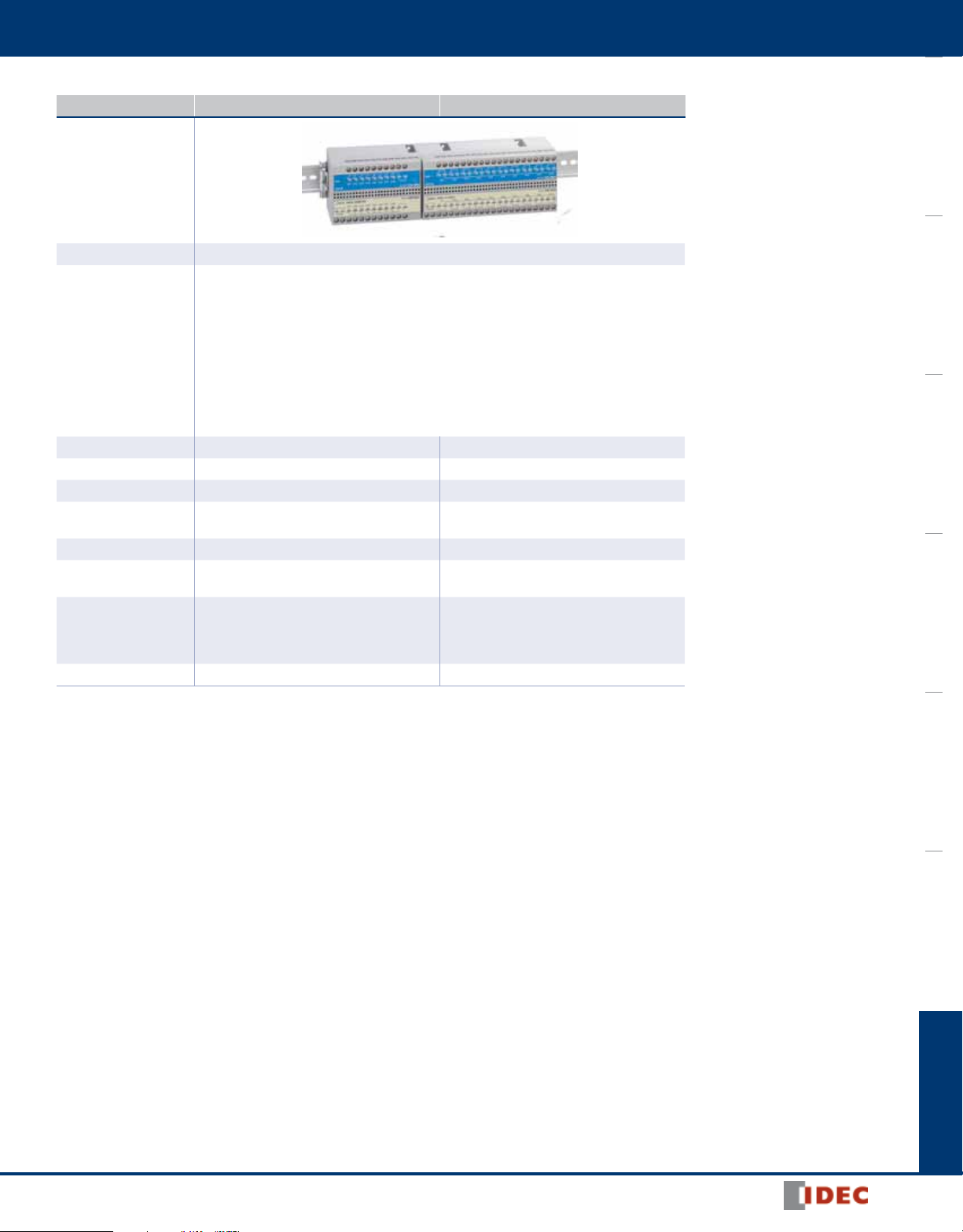
Discrete Input Barrier
Model EB3C-**A EB3C-**D EB3N-**D
OI TouchscreensPLCsAutomation SoftwarePower SuppliesSensorsCommunicationBarriers
Appearance
Page 224 229
UL/FM: Class I, II, III Div1 / Group A, B, C, D, E, F, and G
CSA: Class I Div 1 / Group A, B, C, D
NEMKO: [Exia] II C
Explosion Protection
Degree of Protection IP20 IP20 IP20
Number of Channels
Power Voltage 100 to 240V AC (UL rating: 100- 120VAC) 24V DC 24V DC
Output
Connection Screw Terminal Screw Terminal, Connector Screw Terminal
Mounting
Size
(excluding projections)
Weight (approx.) 380g (EB3C-R10A) 390g (EB3C-R16CD)
CQST: [Exia] II C
GOST-R: [Exia] II C
TIIS: Discrete input barrier [Exia] IIC
Switch (EB9Z-A) [Exia] IICT6
Switch (EB9Z-A1) [Exia] IIBT6
NK: [Exia] II C
KOSHA: [Exia] II C
Relay Output: 1,2,3,5,6,8,10
Transistor Output: 1,2,3,5,6,8,10,16
Relay
Transistor
(Sink/Source)
35-mm-wide DIN rail
Panel mounting
42W×75H×77.5D (1 channel)
65W×75H×77.5D (2, 3 channels)
110.5W×75H×77.5D (5, 6, 8 channels (common))
171.5W×75H×77.5D (8, 10 channels)
Class I, Zone 0 / [AExia] II C
1, 2, 3, 5, 6, 8, 10, 16
Relay
Transistor
(Sink/Source)
35-mm-wide DIN rail
Panel mounting
42W×75H×77.5D (1 channel)
65W×75H×77.5D (2, 3 channels)
110.5W×75H×77.5D (5, 6, 8 channels (common))
171.5W×75H×77.5D (8, 10, 16 channels (common))
UL: Class I, Zone 0, [AExia] II C
Class I, II, III, Div. 1, Groups A, B,
C, D, E, F and G
IEC Ex: [Exia] II C
PTB: II (1) G [Exia] II C
II (1) D [ExiaD]
CQST: [Exia] II C
TIIS: [Exia] II C
EB3N-£2ND: 2 safety circuits
EB3N-£2R5D: 2 safety circuits,
5 auxiliary circuits
Relay
35-mm-wide DIN rail / Panel mounting
65.0W×75.0H×77.5D
(EB3N-£2ND)
110.5W×75.0H×77.5D
(EB3N-£2R5D)
220g (EB3N-£2ND)
300g (EB3N-£2R5D)
222
www.IDEC.com
Barriers
Selection Guide
Discrete Output Barrier
Model EB3L-**A EB3L-**D
Appearance
Page 234
UL/FM: Class I, II, III Div1 / Group A, B, C, D, E, F, and G
Class I, Zone 0 / [AExia] II C
CSA: Class I Div 1 / Group A, B, C, D
Explosion Protection
Degree of Protection IP20 IP20
Number of Channels 1, 2, 3, 5, 6, 8, 10 1, 2, 3, 5, 6, 8, 10, 16
Power Voltage 100 to 240V AC (UL rating: 100 ~ 120V AC) 24V DC
Input
Connection Screw Terminal Screw Terminal, Connector
Mounting
Size
(excluding projections)
Weight (approx.) 360g (EB3L-S10SA) 360g (EB3L-S16CSD)
NEMKO: [Exia] II C
CQST: [Exia] II C
GOST-R: [Exia] II C
TIIS: Discrete output barrier [Exia] II C
NK: [Exia] II C
KOSHA: [Exia] II C
Transistor input (sink)
Transistor input (source)
35-mm-wide DIN rail
Panel mounting
42W×75H×77.5D (1 channel)
65W×75H×77.5D (2, 3 channels)
110.5W×75H×77.5D (5, 6, 8 channels)
171.5W×75H×77.5D (8, 10 channels)
Transistor input (sink)
Transistor input (source)
35-mm-wide DIN rail
Panel mounting
42W×75H×77.5D (1 channel)
65W×75H×77.5D (2, 3 channels)
110.5W×75H×77.5D (5, 6, 8 channels)
171.5W×75H×77.5D (8, 10, 16 channels (common))
OI Touchscreens PLCs Automation Software Power Supplies Sensors Communication Barriers
800-262-IDEC (4332) • USA & Canada
223
EB3C
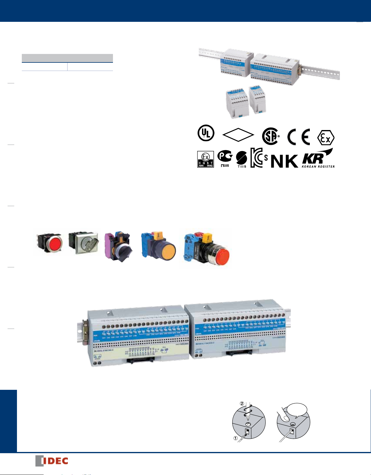
Intrinsically Safe: EB3C Discrete Input Barriers
Key features:
Explosion Protection
Discrete Input Barriers: [Exia] II C
OI TouchscreensPLCsAutomation SoftwarePower SuppliesSensorsCommunicationBarriers
• IEC60079 compliant
• Dry-contact switches can be connected to the EB3C
• 8- and 16-circuit types are available in common wiring types, ideal
for connection to PLCs (DC voltage only)
• Universal AC power voltage (100 to 240V AC) or
24V DC power (UL rating: 100 ~ 120V AC)
• No grounding required
• IDEC’s original spring-up terminals minimizes wiring time
• Installation: 35-mm-wide DIN rail mounting or direct panel mounting
• Global usage
USA: UL/FM
Canada: CSA
Europe: CE marking, ATEX
China: CQST
Russia: GOST-R
Japan: TIIS
Korea: KOSHA
• Ship class: NK (Japan), KR (Korea)
Barriers
FM
LISTED
APPROVED
Dry Contact Switches
Dry-contact switches can be connected to the EB3C.
LB Series
CW Series
Common Wiring for PLC Inputs
8- and 16-circuit types are available in common wiring
types, ideal for connection to PLCs (DC voltage only).
Connector Type
MIL connector on the non-hazardous side
• Easy connection to PLCs
• Wiring is cut by 90% (compared with IDEC’s 16-circuit EB3C)
• Various 20-pin MIL connectors can be connected
HW Series
Spring-up Fingersafe Terminals Reduce
Wiring Time
Finger-safe
224
www.IDEC.com

Barriers
EB3C
Discrete Input Barriers
Power Voltage
100 to 240V AC
(UL rating: 100 ~ 120V AC)
24V DC
*Note: These models are NOT Listed by UL
Part Numbers
Number of
Channels
1
2 EB3C-R02A
3 EB3C-R03A
5 EB3C-R05A
6 EB3C-R06A
8 EB3C-R08A
10 EB3C-R10A
8 Common Wiring Only EB3C-R08CA
1
2 EB3C-T02A
3 EB3C-T03A
5 EB3C-T05A
6 EB3C-T06A
8 EB3C-T08A
10 EB3C-T10A
8
16 EB3C-T16CKA*
8
16 EB3C-T16CSA
1
2 EB3C-R02D
3 EB3C-R03D
5 EB3C-R05D
6 EB3C-R06D
8 EB3C-R08D
10 EB3C-R10D
8
16 EB3C-R16CD
1
2 EB3C-T02D
3 EB3C-T03D
5 EB3C-T05D
6 EB3C-T06D
8 EB3C-T08D
10 EB3C-T10D
8
16 EB3C-T16CKD*
8
16 EB3C-T16CSD
16 Connector Wiring
Connection to
Non-intrinsically
Safe Circuit
Screw Terminal
Input Wiring Method Output Part Number
Separate/Common Wiring Compatible
Separate/Common Wiring Compatible Transistor (Sink/Source)
Common Wiring Only Transistor
Separate/Common Wiring Compatible
Common Wiring Only
Separate/Common Wiring Compatible Transistor (Sink/Source)
Common Wiring Only
Relay
Relay
Transistor
Sink
Source
Sink
Source
Sink EB3C-T16CKD-C*
Source EB3C-T16CSD-C
EB3C-R01A
EB3C-T01A
EB3C-T08CKA*
EB3C-T08CSA
EB3C-R01D
EB3C-R08CD
EB3C-T01D
EB3C-T08CKD*
EB3C-T08CSD
OI Touchscreens PLCs Automation Software Power Supplies Sensors Communication Barriers
Accessories
Item Part Number Description
DIN Rail
End Clip BNL6 Medium DIN rail end clip
BAP1000 Steel (1m long, 7.5mm high)
BNDN1000 Aluminum (1m long, 10.5mm high)
800-262-IDEC (4332) • USA & Canada
225

EB3C
Explosion-Protection and Electrical Specifications
Explosion Protection See Certification Numbers table below
Degree of Protection IP20 (IEC60529)
OI TouchscreensPLCsAutomation SoftwarePower SuppliesSensorsCommunicationBarriers
Discrete Input Barrier
Location
Installation
Non-intrinsically Safe Circuit
Maximum Voltage (Um)
Wiring Method
Rated Operating Voltage 12V DC ±10%
Rated Operating Current 10 mA DC ±20%
Maximum Output Voltage (Uo) 13.2V DC
Maximum Output Current (lo) 14.2 mA 227.2 mA
Maximum Output Power (Po) 46.9 mW 750 mW
Maximum External Inductance (Lo)* 175 (125) mH 0.68 (0.68) mH
Maximum External Capacitance (Co)* 900 (740) nF
Intrinsically Safe Circuits
Allowable Wiring Resistance (Rw) 300Ω
Maximum Channels per Common Line – 16
Contact Configuration 1NO
Rated Insulation Voltage (Ui) 250V AC (UL rating: 125V AC), 125V DC
Thermal Current (lth) 3A (common terminal: 8A)
Contact
Allowable
Power
Rated Load
Minimum Applicable Load 0.1V DC, 0.1 mA (reference value)
Relay Output
Contact Resistance 50 mΩ
ON Time 12 ms maximum (rated voltage)
OFF Time 10 ms maximum (rated voltage)
Mechanical Life
Electrical Life
Non-intrinsically Safe Circuits
Short-circuit Protection None
Rated Voltage 24V DC
Maximum Voltage 30V DC
Maximum Current 100 mA (connector type: 15 mA)
Leakage Current 0.1 mA maximum
Voltage Drop 1V maximum
Clamping Voltage 33V (1W)
Inrush Current 0.5A maximum (1 sec)
Transistor Output
ON Time 0.1 ms maximum (resistive load)
OFF Time 0.4 ms (typical) (resistive load)
Short-circuit Protection None
Resistive Load AC: 750 VA, DC: 72W
Inductive Load
Resistive Load 250V AC 3A, 24V DC 3A
Inductive Load
Safe indoor place
(non-hazardous area)
250V AC 50/60Hz, 250V DC
125V AC 50/60Hz, 125V DC (UL rating)
1-channel
Separate
Wiring
AC: 750 VA (cos ø = 0.3 to 0.4)
DC: 48W (L/R = 7 ms)
250V AC 3A (cos ø = 0.3 to 0.4)
24V DC 2A (L/R = 7 ms)
20,000,000 operations minimum (at
18,000 operations/hour, without load)
100,000 operations minimum
(at 1,800 operations/hour, rated load)
16-channel
Common Wiring
600/(n+1)Ω
(n = number of
common channels)
Barriers
Specifications
General Specifications
Rated Voltage
Allowable Voltage Range
Rated Frequency
Inrush Current
Dielectric Strength
(1 minute, 1 mA)
Operating Temperature –20 to +60°C (no freezing)
Storage Temperature –20 to +60°C (no freezing)
Operating Humidity 45 to 85% RH (no condensation)
Atmosphere 800 to 1100 hPa
Pollution Degree 2 (IEC60664)
Insulation Resistance
Vibration
Resistance
Shock
Resistance
Terminal Style M3 screw terminal
Mounting 35-mm-wide DIN rail or panel mounting (M4 screw)
Power Consumption (approx.)
Weight (approx.) 390g (EB3C-R16CD)
Certification Numbers
Certification
Organization
UL/FM
CSA Class I Div. 1 Groups A, B, C, D 166730
NEMKO [Exia] II C Nemko 02ATEX279
TIIS Japan Relay barrier: [Exia] II C TC15753
Class NK [Exia] II C 02T606
GOST-R [Exia] II C
KOSHA [Exia] II C 11-AV4BO-0457
CQST [Exia] II C CNEx10.2445
AC DC
100 to 240V AC
(UL rating: 100 ~ 120V AC)
85 to 264V AC
(UL rating: 85 ~ 125V AC)
50/60 Hz (allowable range:
47 to 63 Hz)
10A (100V AC)
20A (200V AC)
Between intrinsically safe circuit and non-intrinsi-
cally safe circuit: 1500V AC
Between AC power and output terminal: 1500V AC
Between DC power and transistor output terminal:
1000V AC
10 MΩ minimum (500V DC megger, between the
same poles as the dielectric strength)
Damage Limits
Operation Extremes
(relay output only)
Damage Limits
Class I, II, III Div. 1
Groups A, B, C, D, E, F and G
Class I, Zone 0 AEx [ia] IIC
Class NK is Japan Shipping agency approval, Class KR is Korean shipping agency approval.
Panel mounting: 10 to 55 Hz, amplitude 0.75 mm
DIN rail mounting: 10 to 55 Hz, amplitude 0.35 mm
Panel mounting: 10 to 55 Hz, amplitude 0.5 mm
DIN rail mounting: 10 to 55 Hz, amplitude 0.35 mm
Panel mounting: 500 m/s
DIN rail mounting: 300 m/s2 (3 times each on X, Y, Z)
9.6 VA (EB3C-R10A at 200V AC)
4.8 W (EB3C-R16CD at 24V DC)
Explosion Protection
24V DC
21.6 to 26.4V DC
—
10A
2
(3 times each on X, Y, Z)
Certification
Number
3015417
UL file: E234997
Values in ( ) are those approved by TIIS (Technology Institution of Industrial Safety, Japan).
Note: Um = 125V AC for UL ratings
226
www.IDEC.com

Barriers
A1NL C1 A2 C2 A3 C3
A1 C1 A2 C2 A3 C3
–+
A1–+ A16 C1 C2
EB3C
Circuit Diagrams
Internal Circuit Block Diagrams
AC Power, Relay Output Type
P1 N1 P2 N2 P3 N3
Yellow Yellow Yellow
Green
~
DC Power, Transistor Output Type Connector Wiring, Sink Output Type
• • • • • • • •
P1 N1 P2 N2 P3 N3
Yellow Yellow Yellow
Green
~
~
~
• • • •
P1 P16 N1 N2
Yellow Yellow
Green
~
~
~
• • • •
Wiring Examples
External Wiring Examples
Transistor Sink Output Type (Ex.: EB3C-T08CKD) Transistor Source Output Type (Ex.: EB3C-T08CSD)
P1 P2 P3 P4 P5 P6 P7 P8 N1 N2
OI Touchscreens PLCs Automation Software Power Supplies Sensors Communication Barriers
Hazardous Area
Non-hazardous Area
Relay Output Type (Ex.: EB3C-R06A)
P1 N1 P2 N2 P3 N3 P4 N4 P5 N5 P6 N6
L N A1 C1 A2 C2 A3 C3 A4 C4 A5 C5 A6 C6
AC Power
Load
Load
Load
Load
Load
Load
Load
Power
AC/DC
+ – A1 A2 A3 A4 A5 A6 A7 A8 C1 C2
Load
Load
Load
Load
Load
Load
Load
24V DC
Transistor Output Type (Ex.: EB3C-T06A)
P1 N1 P2 N2 P3 N3 P4 N4 P5 N5 P6 N6
L N A1 C1 A2 C2 A3 C3 A4 C4 A5 C5 A6 C6
AC Power
Load
Load
Load
Load
Load
Load
Load Power
24V DC
Load
Load
Power
24V DC
800-262-IDEC (4332) • USA & Canada
227

EB3C
83.5
ø6
6
(4)
4- ø4.5 holes
77.5
75
97
171.5
10
10
65
97
65
4-M4 or 4-ø4.5 holes
Mounting Hole Layout
EB3C–T16C -C
Connector
5.4 min.3 max.
6 max.
ø3.2 min.
6 to 8 mm
Solid Wire
Stranded Wire (Ferrule)
Stripping the Wire End
Applicable Crimping Terminal
OI TouchscreensPLCsAutomation SoftwarePower SuppliesSensorsCommunicationBarriers
EB3C–*01
42
EB3C–*02
EB3C–*03
Barriers
Dimensions (mm)
EB3C–*05
EB3C–*06
EB3C–*08C
110.565 77.5
EB3C–*08
EB3C–*10
EB3C–*16C
171.5
ø4.4
75
61
ø6 hole
77.5
6
4
10
Mounting Hole Layout (Screw Mounting)
2-M4 tapped or
2-ø4.5 mounting
holes
28 51 97 97
2-M4 tapped or
2-ø4.5 mounting holes
65
2-M4 tapped or
2-ø4.5 mounting holes
4-M4 tapped or
4-ø4.5 mounting holes
65
(4)
10101010
65
228
www.IDEC.com
 Loading...