

Page 1
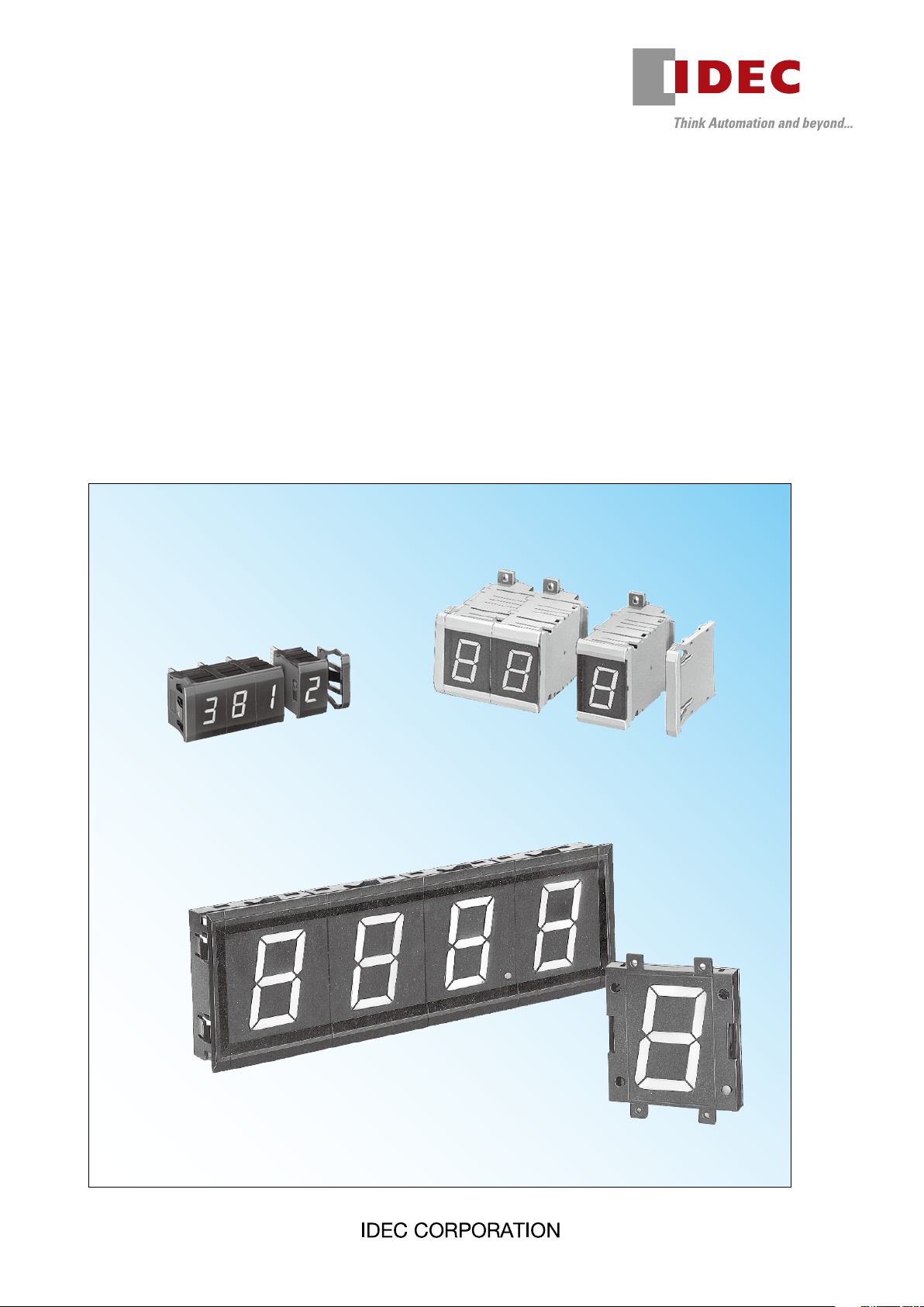
Display Units
DD3S Series DD48 Series
DD96 Series
Page 2
6.2
20
20
14.2
33
20
48
30
2.5
11.1
25.4
14
48
30
57
96
33
72
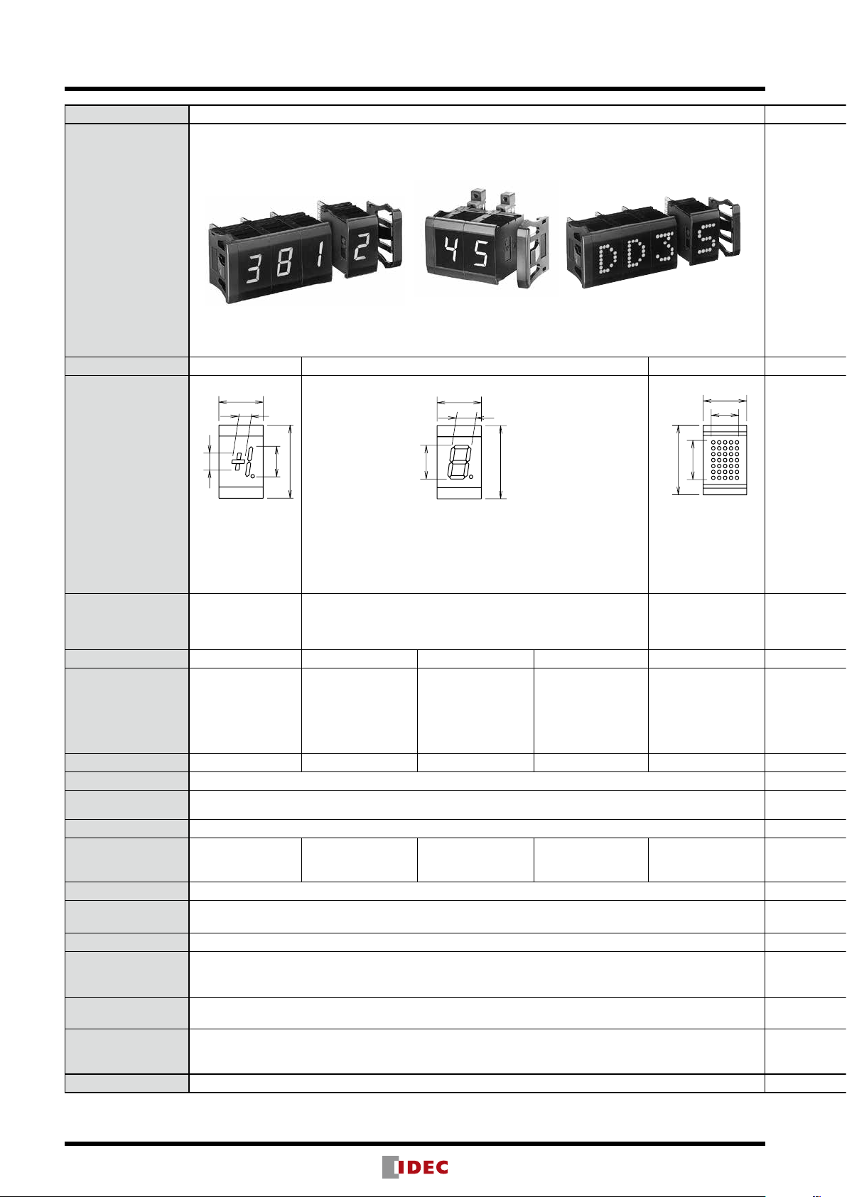
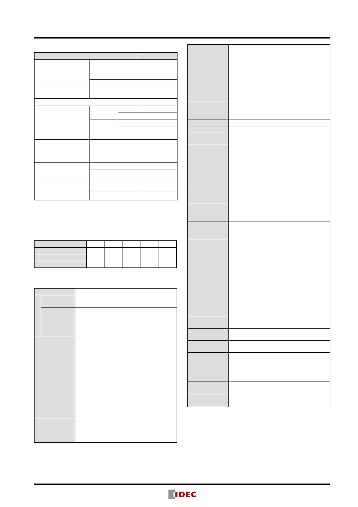
Display Units (Selection Guide)
Series
DD3S DD48 DD96
Shape
Unit Type Binary Decimal/Hexadecimal/Extra Decimal Character Display
6.2
13.2
8.8
33
33
12.7
17.8
Display Part (mm)
Notes:
+, –, 1
Red or green LED
7-segment
Red LED, Green LED
Red/green 2-color alternate LED
The red and green colors of the
single color LEDs are different
from those of the 2-color
Red LED
alternate display.
Display Character
+, –, 1
decimal point
Function Standard Standard 2-color alternate Zero-suppress
+, –, 1
Latch
Input
BL
LT
DP
Output
— — —
Decimal display unit: 0 to 9, decimal point
Hexadecimal display unit: 0 to F, decimal point
Extra decimal display unit: 0 to 9, –, –, –, =, =, decimal point
Binary
Latch
BL
LT
DP
Binary
Latch
R/G
BL
DP
Binary
Latch
BL
LT
RBI
DP
RBO
254 characters
— — — —
Data (8-bit) input
Latch
BL
— —
Input Logic Positive or negative Positive or negative Negative
Data Input Level
L: 0 to 2V
H: 9 to 30V
Power Voltage 12 to 24V DC ±10% 24V DC ±10% 24V DC ±10%
Current Draw
(Power Consumption)
(approx.)
Red: 35 mA max.
Green: 50 mA max.
Red: 40 mA max.
Green: 60 mA max.
60 mA max.
Red: 40 mA max.
Green: 60 mA max.
65 mA max.
No. of Digits 8 digits max. (1 digit/unit) 16 digits max. (1 digit/unit) 8 digits max. (1 digit/unit)
Panel Mounting Front mount, snap t Front mount, snap t
Housing Color Black (End plate: black) Black or beige Black
Connector
•Solder terminal, PC board terminal, wire-wrap terminal (optional)
•Mother board: Dynamic (4- or 2-digit, optional)
•Mother board: 4 digits (optional)
(For character display)
Static (4-, 3-, or 2-digit, optional)
Dimensions
33H × 20W × 45.5D mm/unit 48H × 30W × 79D mm/unit
Weight (approx.)
See Page 4 through 18 19 through 26 27 through 30
Display unit: 16.0g
End plates (pair): 4.5g
2
Page 3
48
30
48
30
96
72
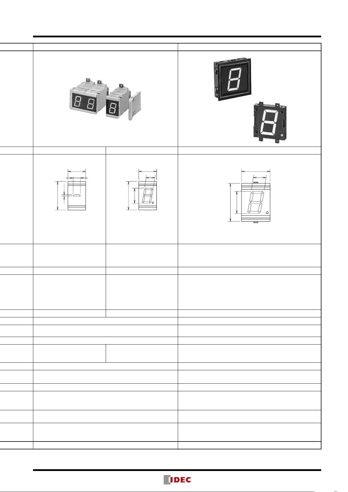
Display Units (Selection Guide)
Front Mount
Rear Mount
Binary Decimal Decimal
2.5
– (minus)
Red or green LED
– (minus)
–
Latch
BL
L: 0 to 2V
H: 12 to 30V
11.1
14
25.4
7-segment
Red or green LED 7-segment
0 to 9
Decimal point
Binary
Latch
DP
RBI
RBO BO
Red LED
0 to 9
Decimal point
Binary
Latch
DP
BI
L: 0 to 2V
H: 12 to 30V
33
57
0.9W 2.0W 80 mA
Front mount: Snap t
Rear mounting: Screw mounting
•Solder terminal, PC board terminal (optional)
•Mother board: 4-digit (optional) for mounting binary and decimal units
Display unit: 50g
End plates: 20g (pair)
•Solder terminal (supplied)
Front mount: 96H × 72W × 42.5D mm/unit
Rear mount: 90H × 72W × 41D mm/unit
Front mount: 130g
Rear mount: 100g
End plates: 26g (pair)
3
Page 4
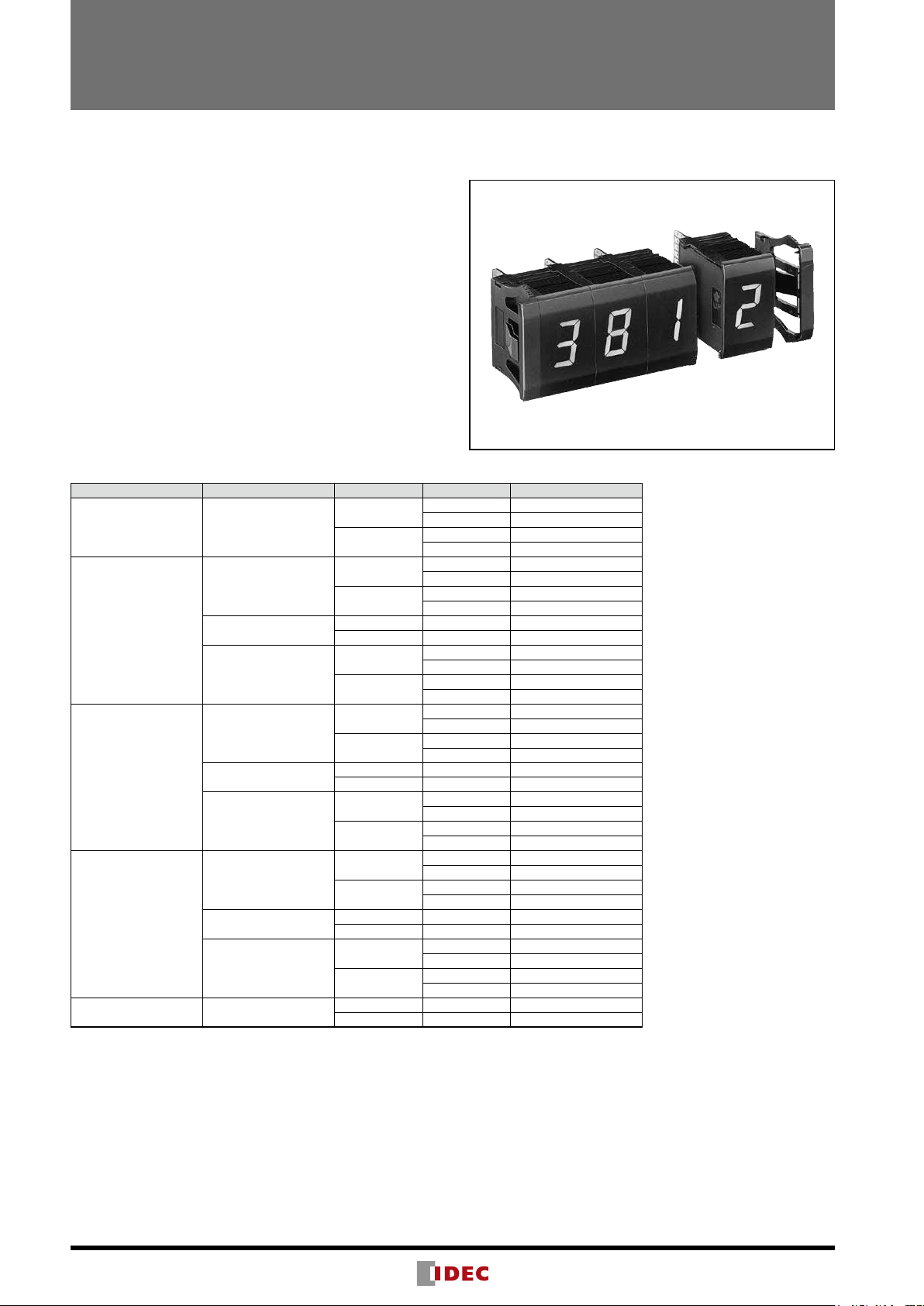
DD3S Series Display Units
7-segment digital display and 5 × 7 dot matrix character display units
Super bright LED display and short body for up to 8 digits
• Super bright LED for easy reading
• Units can be combined together and installed into a panel
cut-out.
• Binary, decimal, hexadecimal, extra decimal, and character
display units are available.
• The character display unit uses 5 × 7 dot matrix LEDs and
can display 254 characters, including katakana, symbols,
units, and simple kanji characters, as well as numbers and
alphabets.
• Positive or negative input logic
• Easy wiring and maintenance
• Power voltage 12 through 24V DC.
• Mother boards are available for dynamic and static display
modes; substantial saving of wiring.
DD3S
Display Units (Housing Color: Black)
Notation Function Input Logic LED Color Part No.
Binary Standard
Decimal
Extra Decimal
Hexadecimal
Character Display
Standard
2-color Alternate
Zero-suppress
Standard
2-color Alternate
Zero-suppress
Standard
2-color Alternate
Zero-suppress
Positive
Negative
Positive
Negative
Positive R/G DD3S-F31P-RG
Negative R/G DD3S-F31N-RG
Positive
Negative
Positive
Negative
Positive R/G DD3S-F34P-RG
Negative R/G DD3S-F34N-RG
Positive
Negative
Positive
Negative
Positive R/G DD3S-F36P-RG
Negative R/G DD3S-F36N-RG
Positive
Negative
Positive Red DD3S-F57P-R
Negative Red DD3S-F57N-R
Red DD3S-F01P-R
Green DD3S-F01P-G
Red DD3S-F01N-R
Green DD3S-F01N-G
Red DD3S-F31P-R
Green DD3S-F31P-G
Red DD3S-F31N-R
Green DD3S-F31N-G
Red DD3S-F31P-R-S
Green DD3S-F31P-G-S
Red DD3S-F31N-R-S
Green DD3S-F31N-G-S
Red DD3S-F34P-R
Green DD3S-F34P-G
Red DD3S-F34N-R
Green DD3S-F34N-G
Red DD3S-F34P-R-S
Green DD3S-F34P-G-S
Red DD3S-F34N-R-S
Green DD3S-F34N-G-S
Red DD3S-F36P-R
Green DD3S-F36P-G
Red DD3S-F36N-R
Green DD3S-F36N-G
Red DD3S-F36P-R-S
Green DD3S-F36P-G-S
Red DD3S-F36N-R-S
Green DD3S-F36N-G-S
Ordering Information
1. Specify the Part No. and quantity of the display units and accessories.
(Example) Display Unit DD3S-F31P-R 8 pcs
Accessories
•SpacerUnit DD9Z-FY1-B 1pc
•EndPlate DD9Z-W-B 1set
•MotherBoard DD9Z-MB1-4 2pcs
2. Order spacer units, end plates, and mother boards separately.
See the next page.
4
Page 5
DD3S Series Display Units
Accessories (Optional)
Name Part No.
Spacer Unit Black DD9Z-FY1-B
End Plate (pair) Black DD9Z-W-B
Connector
Retentive/One-way
Insertion Connector
Connector Stopper DD9Z-ST1
Mother Board
for binary/decimal/hex/
extra decimal display
unit
Mother Board
for 5 × 7 dot matrix
character display unit
(with spacer)
Mother Board
Connector
Coupling Spacer
for IDEC DG Series
Digital Switches
Solder Terminal DMC-1
PC Board Terminal DMC-2
Solder Terminal DD9Z-CN1
Dynamic
Static
Type A
Type B
Type C
Right Side Black DD9Z-FG1R-B
Left Side Black DD9Z-FG1L-B
4-digit DD9Z-MB1-4
2-digit DD9Z-MB1-2
4-digit DD9Z-MB2-4
3-digit DD9Z-MB2-3
2-digit DD9Z-MB2-2
4-digit DD9Z-MB3-4
DD9Z-JE1A
DD9Z-JE1B
DD9Z-JE1C
Cable Length Code
Specify a cable length code in place of in the Part No. of mother
board cable types A, B, and C. These cables can be used for both
dynamic and static type mother boards.
Code 01 02 03 05 10
Cable Length (mm) 100 200 300 500 1000
Code 15 20 30 40 50
Cable Length (mm) 1500 2000 3000 4000 5000
Specifications
Power Voltage 12 to 24V DC ±10%
Binary
Decimal/
Hex/
Extra decimal
Character
Current Draw
Display
Data Input Level
Display
Character
(see Function
Tables)
Character Height
35 mA max. (red)
50 mA max. (green)
40 mA max. (red)
60 mA max. (green)
2-color: 60 mA max. (green)
65 mA max.
L: 0 to 2V
H: 9 to 30V
•Binary display unit
Red or green LED: +, –, 1, decimal point
•Decimal display unit
7-segment 1-color (red or green), 2-color
(red/green) LED: 0 to 9, decimal point
•Hexadecimal display unit
7-segment 1-color (red or green), 2-color
(red/green) LED: 0 to 9, A to F, decimal point
•Extra decimal display unit
7-segment 1-color (red or green), 2-color
(red/green) LED: 0 to 9, –, –, –, =, =, decimal
point
•Binary display unit: 15 mm
•Decimal/Hex/Extra Decimal display units:
15.2 mm (2-color: 15 mm)
•Character display unit: 17.8H × 12.7W mm
•Binary display unit
+, –, 1, Latch, BL, LT, DP
•Decimal/Hex/Extra Decimal display units:
<Standard>
Input
Output
Input Logic Positive or negative
No. of Digits 8 digits max.
Unit
Combination
Panel Mounting Snap t
Dielectric
Strength
Insulation
Resistance
Vibration
Resistance
(damage limits)
Shock
Resistance
(damage limits)
Noise
Resistance
(operating
extremes)
Operating
Temperature
Storage
Temperature
Operating
Humidity
Power Inrush
Current
Degree of
Protection
Weight (Approx.)
Binary, Latch, BL, LT, DP
<Zero-suppress>
Binary, Latch, BL, LT, DP, RBI
<2-color>
Binary, Latch, BL, R/G, DP
•Character display unit: D0 to D7, Latch, BL
•Decimal/Hex/Extra Decimal display units:
<Zero-suppress>
RBO output
Snap t
•Binary/Decimal/Hex/Extra decimal display
units
Between live and dead parts :
1500V DC, 1 minute
•Character display unit
Between live and dead parts :
1000V AC, 1 minute
Between live and dead parts :
100 MΩ min. (500V DC megger)
10 to 55 Hz, amplitude 0.25 mm
490 m/s²
•Binary/Decimal/Hex/Extra decimal display
unit
Power terminal (normal/common modes):
±1000V
Input terminal (normal/common modes):
±1000V
Output terminal (normal/common modes):
±500V
(Impulse condition: Pulse width 100 ns,
•Character display unit
Fast transient burst noise
Power supply: 2 kV, Signal: 1 kV
(IEC61000-4-4 capacitive clamp)
–10 to +55°C (no freezing)
–25 to +80°C (no freezing)
35 to 85% RH (no condensation)
•Binary/Decimal/Hex/Extra decimal display
unit
Approx. 2.0A (Power voltage: 24V)
•Character display unit
Approx. 1.0A (Power voltage: 24V)
IP40 (IEC60529)
•Display unit: 16g
•End plates: 4.5g (pair)
1 μs)
5
Page 6
DD3S Series Display Units
(Terminal No.)
Power
12 to 24V DC
(Terminal No.)
(Terminal No.)
Power
(Terminal No.)
12 to 24V DC
200 kΩ
Data Input
GND
(Terminal No.)
Power
(Terminal No.)
12 to 24V DC
Data Inpu
GND
12 to 24V DC
(Terminal No.)
Power
(Terminal No.)
12 to 24V DC
Control Input
(Terminal No.)
Power
(Terminal No.)
470 kΩ
Data Inpu
Data Inpu
GND
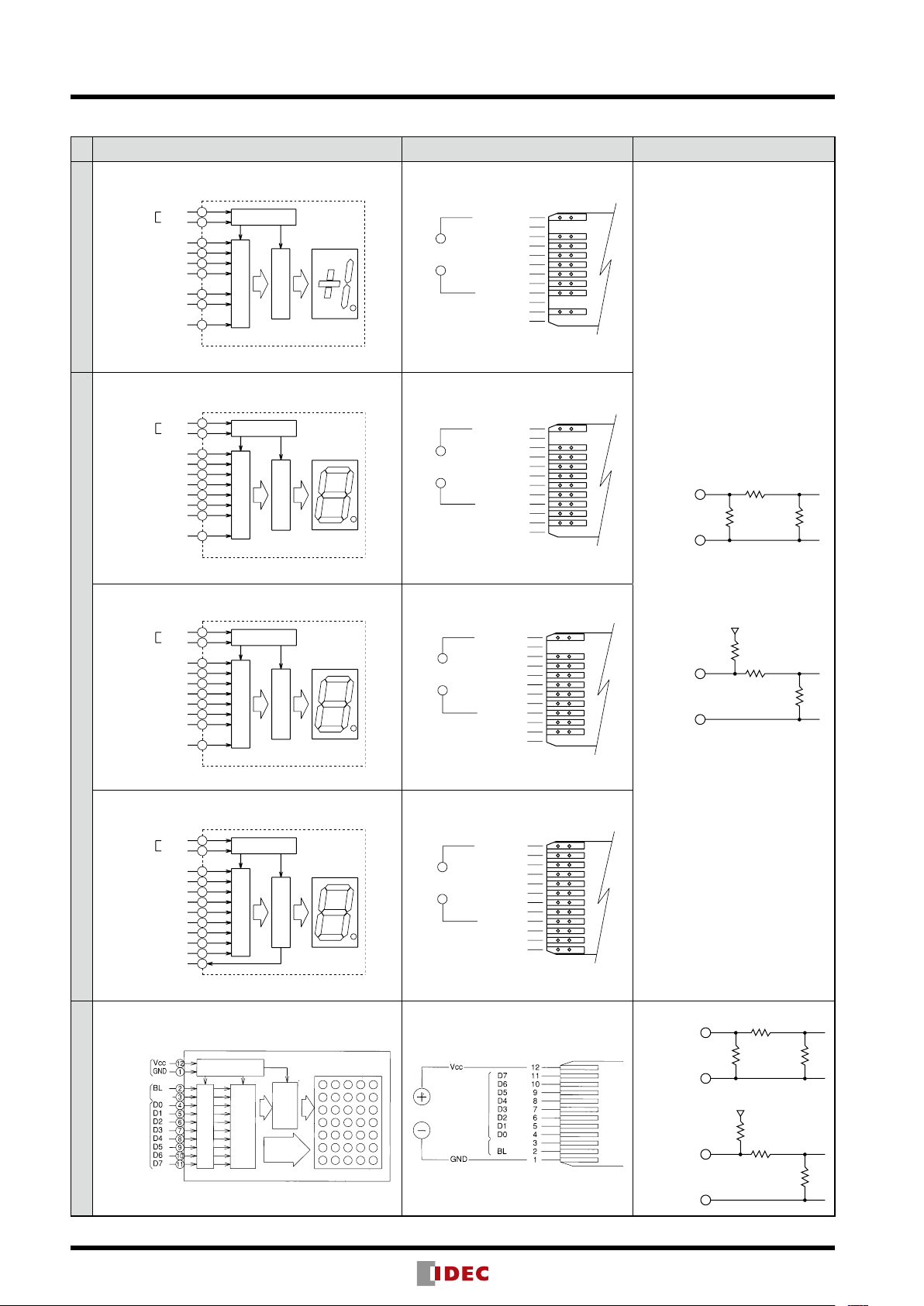
Terminal Connection
Connection Diagram Terminal Arrangement Internal Input Circuit
Standard Standard
4
Vcc
GND
Latch
+
–
1
BL
Binary Display Unit
LT
DP
Standard Standard
Vcc
GND
Latch
0
)
A (2
1
)
B (2
2
)
C (2
3
)
D (2
BL
LT
DP
12
8
10
9
5
7
6
2
4
12
8
10
3
5
9
7
6
2
Regulating Circuit
Input Circuit
Regulating Circuit
Input Circuit
Decoder
Decoder
−
Power
+
−
Power
+
12. GND
11. NC
+
10.
–
9.
8. Latch
7. BL
6. LT
5. 1
4. Vcc
3. NC
2. DP
1. NC
12. GND
11. NC
10. A (2
9. D (2
8. Latch
7. BL
6. LT
5. C (2
4. Vcc
3. B (2
2. DP
1. NC
0
)
3
)
2
)
1
)
Positive Logic
12 kΩ
200 kΩ
6
2-color Alternate Display 2-color Alternate Display
4
GND
Latch
A (2
B (2
C (2
D (2
Vcc
R/G
0
)
1
)
2
)
3
)
BL
DP
12
8
10
3
5
9
7
6
2
Regulating Circuit
Input Circuit
GND
12.
NC
11.
A (2
10.
−
Power
+
Decoder
D (2
9.
Latch
8.
BL
7.
6. R/G
C (2
5.
Vcc
4.
B (2
3.
DP
2.
NC
1.
Zero-suppress Zero-suppress
Decimal/Hexadecimal/Extra Decimal Display Units
4
Data Input
Power
Latch
GND
Latch
A (2
B (2
C (2
D (2
RBO
Vcc
RBI
0
)
1
)
2
)
3
)
BL
LT
DP
Regulating Circuit
12
8
10
3
5
9
7
Input Circuit
6
1
2
11
Regulating Circuit
Input Circuit
Decoder
Microprocessor
5 x 7 dot matrix LED
Driver
−
Power
+
Data Input
Control Input
GND
12.
11. RBO
A (2
10.
D (2
9.
Latch
8.
BL
7.
LT
6.
C (2
5.
Vcc
4.
B (2
3.
DP
2.
1. RBI
Latch
Character Display Unit
Negative Logic
0
)
3
)
2
)
1
)
0
)
3
)
2
)
1
)
t
12 kΩ
200 kΩ
200 kΩ
Positive Logic
t
12 kΩ
GND
Negative Logic
t
470 kΩ
12 to 24V DC
12 kΩ
470 kΩ
470 kΩ
Page 7
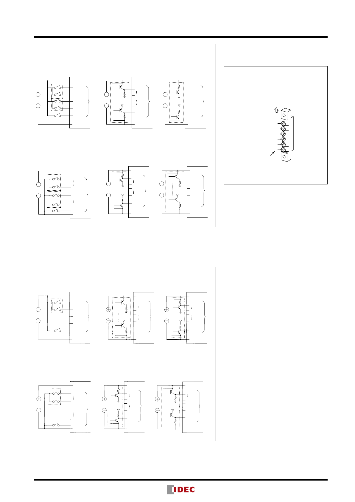
External Wiring
Power
Data
Power
When Tr is on, output goes to H. When Tr is off, output goes to H.
Power
Data
Power
Data
Input
When Tr is on, output goes to L. When Tr is off, output goes to L.
Power
When Tr is on, output goes to H. When Tr is off, output goes to H.
Data
Power
When Tr is on, output goes to L. When Tr is off, output goes to L.
Data
UP Making Side
Connector
Terminal No.
Binary/Decimal/Hexadecimal/Extra Decimal Display Units
Positive Logic
[Contact Input (Digital Switch)] [Transistor Input]
DD3S Series Display Units
Vcc (+)
A
+
−
D
NC
NC
Latch
GND (–)
Input
Tr
+
−
Tr
Vcc (+)
A
R1
D
NC
NC
Latch
R1
GND (–)
Data
Input
+
Power
−
Vcc (+)
R2
A
Tr
D
NC
NC
Latch
GND (–)
Data
Input
+V+V
R2
Tr
Negative Logic
[Contact Input (Digital Switch)] [Transistor Input]
Vcc (+)
+
−
A
D
NC
NC
Latch
GND (–)
Input
Tr
+
−
Tr
Vcc (+)
R1
A
D
NC
Data
Input
NC
R1
Latch
GND (–)
Tr
+
Power
−
Tr
Note: When connecting pull-up or pull-down resistors to the external circuit, refer to the resistor
values shown below:
R1: 2.2 kΩ (1/2W) to 10 kΩ (1/4W)
R2: 1 kΩ (1W) to 2.2 kΩ (1/2W)
R3: 1 kΩ (1W)
Vcc (+)
A
R3
D
NC
+V+V
NC
Latch
R3
GND (–)
Connector Terminal No.
(DMC-1)
12
11
10
9
8
7
6
5
4
3
2
1
Character Display Units
Positive Logic
[Contact Input (Digital Switch)] [Transistor Input]
Vcc (+)
D0
+
−
D7
NC
NC
Latch
GND (–)
Data
Input
Tr
Power
Tr
Negative Logic
[Contact Input (Digital Switch)] [Transistor Input]
Vcc (+)
D0
D7
Data
NC
Input
NC
Latch
GND (–)
Note: When connecting pull-up or pull-down resistors to the external circuit, refer to the resistor
values shown below:
R1: 2.2 kΩ (1/2W) to 10 kΩ (1/4W)
R2: 1 kΩ (1W) to 2.2 kΩ (1/2W)
R3: 1 kΩ (1W)
R1
Tr
Power Power
R1
Tr
Vcc (+)
D0
R1
D7
NC
Data
+V
NC
Latch
R1
GND (–)
Vcc (+)
D0
D7
NC
Data
Input
NC
Latch
GND (–)
Input
Power
Tr
Tr
+V+V
R3
Vcc (+)
R2
D0
Tr
D7
NC
+V
R2
Tr
Vcc (+)
D0
D7
NC
NC
Latch
GND (–)
NC
Latch
GND (–)
Input
Input
7
Page 8
DD3S Series Display Units
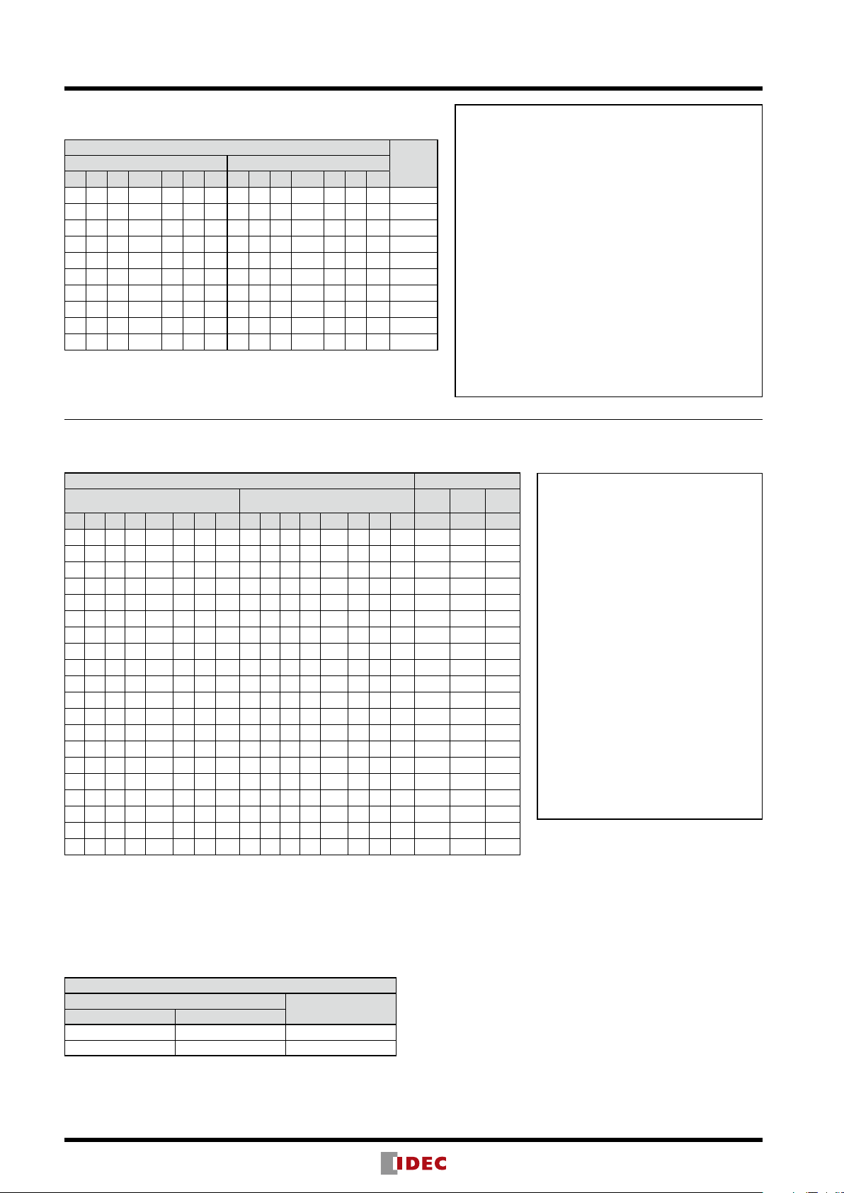
Function Table
Binary Display Unit (Standard)
Data Input
Positive Logic Negative Logic
1 + – Latch LT BL DP 1 + – Latch LT BL DP
× × × × H × × × × × × L × × +1.
× × × × L H × × × × × H L × blank
× × × × L L H × × × × H H L
L L L L L L L H H H H H H H blank
L L H L L L L H H L H H H H
L H × L L L L H L × H H H H +
H L L L L L L L H H H H H H 1
H L H L L L L L H L H H H H
H H × L L L L L L × H H H H +1
× × × H L L L × × × L H H H maintain
Note 1: × indicates the display is not affected by voltage level of H or L.
Note 2: * A decimal point is displayed with any character.
LED
Display
*.
-
-
1
Input Functions
1, +, and – Inputs
When the 1, +, or – input is set to level H for the positive
logic or level L for the negative logic, the 1, +, or – display
is turned on, respectively.
Latch Input
When the Latch input is set to level H for the positive logic
or level L for the negative logic, the 1, +, or – display at the
time is maintained. (DP input is independent.)
LT (Light Test) Input
When the LT input is set to level H for the positive logic or
level L for the negative logic, the entire display turns on.
BL (Blank) Input
When the BL input is set to level H for the positive logic
or level L for the negative logic, the entire display turns off
regardless of other inputs.
DP (Decimal Point) Input
When the DP input is set to level H for the positive logic or
level L for the negative logic, the decimal point turns on.
Decimal/Hexadecimal/Extra Decimal Display Units
(Standard, 2-color Alternate, and Zero-suppress)
Data Input LED Display
Positive Logic Negative Logic Dec. Hex.
D C B A Latch LT BL DP D C B A Latch LT BL DP
× × × × × H × × × × × × × L × × 8. 8. 8.
× × × × × L H × × × × × × H L × blank blank blank
× × × × × L L H × × × × × H H L
L L L L L L L L H H H H H H H H 0 0 0
L L L H L L L L H H H L H H H H 1 1 1
L L H L L L L L H H L H H H H H 2 2 2
L L H H L L L L H H L L H H H H 3 3 3
L H L L L L L L H L H H H H H H 4 4 4
L H L H L L L L H L H L H H H H 5 5 5
L H H L L L L L H L L H H H H H 6 6 6
L H H H L L L L H L L L H H H H 7 7 7
H L L L L L L L L H H H H H H H 8 8 8
H L L H L L L L L H H L H H H H 9 9 9
H L H L L L L L L H L H H H H H blank A –
H L H H L L L L L H L L H H H H blank b _
H H L L L L L L L L H H H H H H blank C
H H L H L L L L L L H L H H H H blank d
H H H L L L L L L L L H H H H H blank E
H H H H L L L L L L L L H H H H blank F blank
× × × × H L L L × × × × L H H
Note 1: × indicates the display is not affected by voltage level of H or L.
Note 2: * A decimal point is displayed with any character.
Note 3: The 2-color alternate does not have the LT terminal.
*. *. *.
maintain maintain maintain
H
Extra
Dec.
¯
=
=
Input Functions
A, B, C, and D (binary code) Inputs
These inputs are decimal or data
corresponding to 1, 2, 4, and 8,
respectively.
Latch Input
When the Latch input is set to level H
for the positive logic or level L for the
negative logic, the display at the time is
maintained. (DP input is independent.)
LT (Light Test) Input
When the LT input is set to level H for the
positive logic or level L for the negative
logic, the entire display turns on.
BL (Blank) Input
When the BL input is set to level H
for the positive logic or level L for the
negative logic, the entire display turns off
regardless of other inputs.
DP (Decimal Point) Input
When the DP input is set to level H for the
positive logic or level L for the negative
logic, the decimal point turns on.
(2-color Alternate Unit)
The display color is switched between red and green using the R/G (No. 6) terminal.
For other inputs, refer to the above table.
The 2-color alternate unit does not have an LT terminal.
Decimal/Hexadecimal/Extra Decimal
R/G Input
Positive Logic Negative Logic
L H Red
H L Green
Display Color
8
Page 9
DD3S Series Display Units
1st Digit2nd Digit3rd Digit4th Digit
[
[
[
(Zero-suppress Unit)
Leading zeros are suppressed using the RBI (No. 1) and RBO (No. 11) terminals. For other
inputs, see the lower table on the preceding page.
Decimal/Hexadecimal/Extra Decimal
Data Input
Positive Logic Negative Logic
X Latch LT BL DP RBI RBO Y Latch LT BL DP RBI RBO
× × H × × × # × × L × × × & 8.
× × L H × × # × × H L × × & blank
H L L L L L L H H H H H L L blank
H L L L L H H H H H H H H H 0
H L L L H L H H H H H L L H 0.
L L L L L L H L H H H H L H
X: X = A · B · C · D *: Any display
Y:Y=A·B·C·D #:# = DP · RBI · X
×: Either H or L &: & = DP · RBI·Y
Note: RBI and RBO operate in the negative logic mode on both positive and negative logic units.
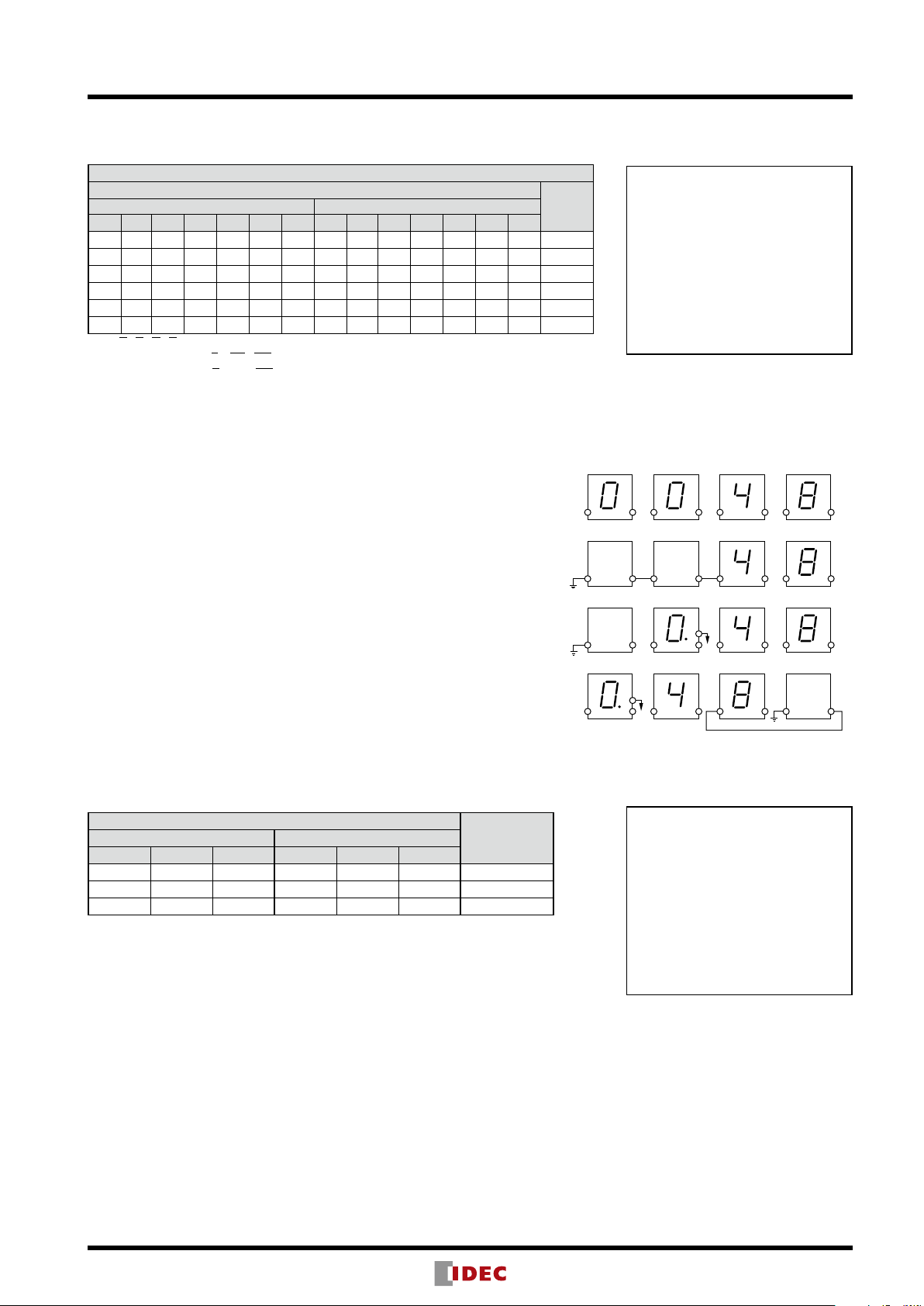
Application Examples of RBI and RBO
[Ex.1] Leading zeros are also displayed. RBI and RBO outputs are
disconnected.
LED
Display
*
[
Ex. 1
]
Input and Output Functions
RBI Input
When 0 is displayed and the decimal
point is turned off, the display is
blanked by setting the RBI input to
level L.
RBO Output
The RBO output remains in level L
during zero blanking. Leading zeros
can be suppressed by connecting the
RBO to the RBI on the lower digits.
The RBO output is an open collector output.
RBI RBO
RBI RBO
RBI RBO
RBI RBO
[Ex.2] Leading zeros on the upper three digits are suppressed. When the data
on the 1st digit is zero, 0 is displayed.
[Ex.3] Zero on the 4th digit is suppressed. Zero and decimal point are
displayed on the 3rd digit.
[Ex.4] Trailing zeros on the 2nd and 1st digits are suppressed. When the data
on the 1st and 4th digits are zero, and the decimal point on the 4th digit
is on, 0.0 is displayed with zeros on the 2nd and 1st digits suppressed.
Note: Use the RBO output only for connection to the RBI input. Do not use the RBO for
other connections.
(Character Display Unit)
Data Input
Positive Logic Negative Logic
D0 to D7 Latch BL D0 to D7 Latch BL
∆
× × H × × L blank
× H × × L × maintain
Note 1: Refer to the character display patterns on the next page.
Note 2: Display is not affected whether × is level H or L.
Note 3: Data (D0 to D7) immediately before the Latch signal is input is maintained.
L L
∆
H H
∆
LED
Display
(Note1)
(Note3)
Ex. 2
Ex. 3
Ex. 4
]
]
]
RBI RBO
RBI RBO
RBI RBO
RBI RBO
RBI RBO
DP
RBI RBO
L or
H
RBI RBO
DP
RBI RBO
L or
H
RBI RBO
Input Functions
Latch Input
When the Latch Input is set to level H
for the positive logic or level L for the
negative logic, the display at the time
is maintained.
BL (Blank) Input
When the BL input is set to level H
for the positive logic or level L for the
negative logic, the entire display turns
off regardless of other inputs.
RBI RBO
RBI RBO
RBI RBO
9
Page 10
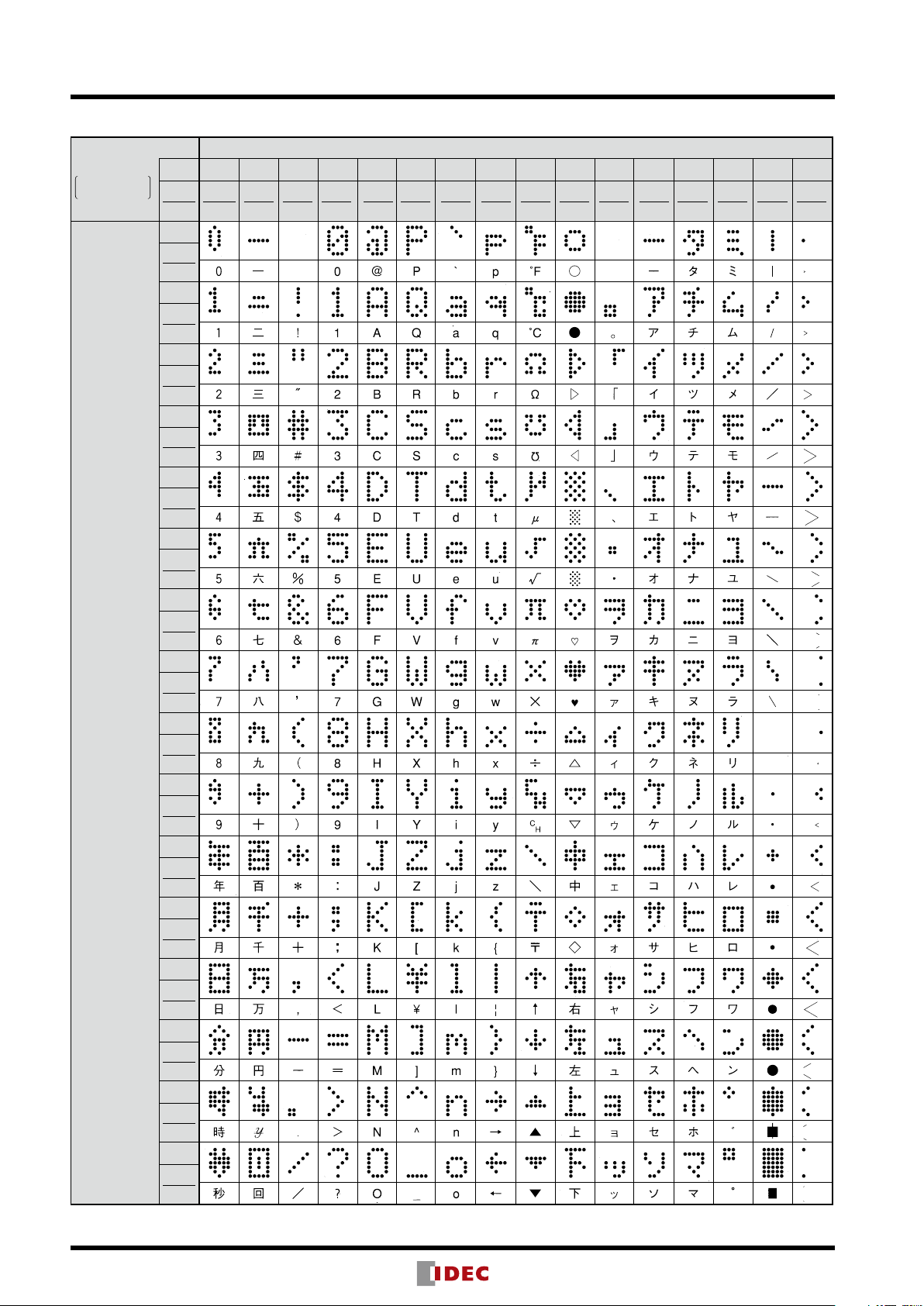
DD3S Series Display Units
D7, D6, D5, D4 (High-bit data)
EF
Note: 8-bit codes for Roman and katakana characters conforming to JIS X0201 (former C6220)
Display Patterns of the Character Display Unit
Data Input
1: Level H
0: Level L
D3, D2, D1,
D0
(Low-bit data)
Positive
Logic
Negative
Logic
0
0000
1111
1
0001
1110
2
0010
1101
3
0011
1100
4
0100
1011
5
0101
1010
6
0110
1001
7
0111
1 000
8
1000
0111
9
1001
0110
A
1010
0101
B
1011
0100
C
1100
0011
D
1101
0010
E
1110
0001
F
1111
0000
0123456789ABCD
1101
1100
1011
1010
1001
1000
0111
0110
0101
0100
0011
0010
0001
0000
0010
0011
0100
0101
0110
0111
1000
1001
1010
1011
1100
1101
1110
1111
1110
0001
1111
0000
10
Page 11

DD3S Series Display Units
End Plate
Character Display Unit
+0.5
+0.5
20N + 10.5 3.5 min.
30.516 min.
(when mounting
more than 8 units)
When using a static mother board
Connector for Data Input
Connector
Spacer
DD3S Housing
PC Board
10
11
12
12-ø3.2 (for mounting mother board)
Note: 38 mm for 2-digit mother board DD9Z-MB1-2
55
Applicable Wire: ø0.8mm maximum
12-ø1 Holes
Applicable PC board thickness: 1.6
Dimensions & Panel Cut-out All dimensions in mm.
Binary
Display Unit
Dec/Hex
Display Unit
Spacer Unit
DD9Z-FY1-8
Panel Thickness 0.8 to 4
Panel Cut-out
For Connector Wiring
For Use of Dynamic Mother Board
0
33
6.5 2020 20 20 6.5
20N + 13
IGHT
30
0
10
423.5
)
∗
(21 min.
N = No. of digits (N ≤ 8)
∗
6.5
Display units can be combined
for up to 8 digits.
Accessories (Optional)
Connector
Solder Terminal Connector PC Board Terminal Connector Retentive/One-way Insertion Connector
(DMC-1) (DMC-2) (DD9Z-CN1) (Note)
AWG #22 maximum
11.3
6
IGHT
42
45.
33
45
0.6
411.3
2.5 × 11
2
UP
35
DD9Z-CN1
20
12
11
10
9
8
7
6
33
4
35
2
1
1.55 1.7 6.813.1
Note: Use DD9Z-CN1 in combination with DD9Z-ST1 connector
stopper.
27.8
(min25)
13.5
13
1.6
5
6
Dynamic Mother Board (not applicable to zero-suppress)
4-digit: DD9Z-MB1-4
2-digit: DD9Z-MB1-2
Screw
Spacer
1.5
3
(
)(
10
9
8
7
6
5
4
3
2
1
13
20 20 20
3-ø2.8 (for securing DD3S)
2
1
)(
10
)(
10
78 (Note)
Substrate: Glass epoxy, 1.6-mm
thick
4.5
)
26.9
(
DMC-2
UP
Nut
45
Latch (10
Latch (10
7* (10
7* (10
DP (10
DP (10
13.5
10 6
10
11.3
1.6
)
45.5
(
0
)
39
14
Note: The DD3S housing can be secured to the mother board using screws.
Recommended tightening torque is 3.5 N·m at the maximum. When
no spacer is used, the tightening torque must not exceed 2 N·m.
Screws (M2.6 × 18), M2.6-3 nuts, and spacers are supplied with
DD3S
Housing
the mother board.
Input Terminal Arrangement
GND
<+> A
<1> C
Latch (10
7* (10
DP (10
For 2-digit
(Top View)
1 2
3 4
5 6
0
7 8
)
9 10
NC
0
11 12
)
13 14
NC
*
15 16
6
1
17 18
)
19 20
NC
*
11
B
D <–>
Latch (10
NC
7* (10
NC
DP (10
NC
Vcc
For 4-digit
GND
<+> A
<1> C
(Top View)
0
)
2
)
0
)
2
)
*
6
1
)
3
)
1 2
3 4
5 6
7 8
9 10
11 12
13 14
15 16
17 18
19 20
*
11
B
D <–>
Latch (10
Latch (10
1
7* (10
3
7* (10
DP (10
DP (10
Vcc
1
)
3
)
)
)
0
)
2
)
Numbers marked with * are the DD3S terminal numbers.
Screw M2.6 × 18
Nut
(M2.6)
Terminal Arrangement
by Models
2-
color
F3**F01**F3
GND
NC
A
1
D
)
1
LAT
BL
)
R/G
0
C
)
Vcc
B
DP
NC
Standard
GND
NC
+
LAT
BL
LT
1
Vcc
NC
DP
NC
GND
NC
A
D
LAT
BL
LT
C
Vcc
B
DP
NC
No.
**
12
11
10
9
8
7
6
5
4
3
2
1
11
Page 12

DD3S Series Display Units
4-ø3.2 (for mounting mother board)
10
Terminal Arrangement
2-ø2.8 (for securing DD3S)
10
10
Terminal Arrangement
ø2.8 (for securing DD3S)
Jumper pin for selection
of terminal block 2
10
10
Terminal Arrangement
4.5
1.5
Connector for Data Input
Connector
Spacer
DD3S Housing
PC Board
Static Mother Board (not applicable to zero-suppress)
4-digit: DD9Z-MB2-4
3-digit: DD9Z-MB2-3
2-digit: DD9Z-MB2-2
Screw
4-digit
10
12
11
10
9
8
7
6
5
4
3
2
1
Terminal Block for Data Input
Decimal Point Jumper Pin
Decimal Point Jumper Socket
Spacer
3-ø2.8 (for securing DD3S)
2
3
)(
10
3
DP(10 )DP(10
7
20 20 201314
1
)(
)
10
2
)
DP(10
78
0
(
)(
10
1
)
5.8
13.5
39
22.5
2.8
)
26.9
(
1.6
50
)
(
45.5
11.3
10
DMC-2
UP
Input Terminal Arrangement
20
19
<+>A
A
1718
B
1516
<1>
C
<
-
>
1314
D
12
11
<+>
A
10
9
B
8
7
<1>
C
56
-
><->
<
D
3
4
GND
2
1
Vcc
B
C
D
A
B
C
D
GND
Vcc
0
1
Nut
DD3S
Housing
<+>
10
<1>
<
-
>
<+>
10
<1>
2
(
TOP VIEW
3
)
Vcc
Latch
(For all 4 digits)
7
(
GND
12345
Note: The DD3S housing can be secured to the mother board
using screws. Recommended tightening torque is 0.35
N·m at the maximum. When no spacer is used, the
tightening torque must not exceed 0.2 N·m.
Screw M2.6 × 18
Nut
(M2.6)
Screws (M2.6 × 18), M2.6 nuts, and spacers are supplied
with the mother board.
by Models
2-color Standard
F3** F3**F01*
GND
GND
NC
Decimal Point Jumper
)
Negative
)
)
6
11
(
(
6
Logic
(–)
(+)
Positive
Logic
NC
A
+
D
−
LATLAT LAT
BL
BL
R/G
LT
C
1
Vcc
Vcc
B
NC
DP
DP
NC
NC
GND
NC
A
D
BL
LT
C
Vcc
B
DP
NC
No.
12
11
10
9
8
7
6
5
4
3
2
1
3-digit
2-digit
12
2
)(
10
10
12
11
2
)
DP(10
10
9
8
7
6
5
4
3
2
1
7
20
1
Jumper pin for (10¹)
decimal point
0
1
(
)
10
1
)
DP(10
13 5.8
20 14
58
)
10
12
11
10
9
8
7
6
5
4
3
2
1
7
13
20 14
)(
01
(
)(
10
38
by Models
2-color Standard
22.5
39
50
2.8
Input Terminal Arrangement
20
19
18
17
B
16
15
C
13
14
D
1112
A
10
9
B
8
7
C
56
>
D
34
2
1
VccNCVcc
<+>
A
B
2
10
<1>
C
-
>
<
D
NC
NC
NC
GND
GND
123456
<+>A
0
<1>
<->
<+>
1
<1>
<
-
GND
(
TOP VIEW
Vcc
Latch
(For all 3 digits)
Decimal Point Jumper
)
Negative
Logic
)
)
)
7
6
11
(
(
(
(–)
(+)
Positive
Logic
F3** F3**F01*
GND
GND
NC
NC
A
+
D
−
LATLAT LAT
BL
BL
LT
R/G
1
C
Vcc
Vcc
NC
B
DP
DP
NC
NC
GND
NC
A
D
BL
LT
C
Vcc
B
DP
NC
No.
12
11
10
9
8
7
6
5
4
3
2
1
by Models
Input Terminal Arrangement
22.5
39
50
5.8
2.8
1920
<+>A
1718
NC
B
0
1516
NC
<1>
-
>
<
<+>
<
-
>
1
<1>
<
-
>
GND
VccNCVcc
C
D
A
B
C
D
(
13
14
NC
1112
NC
910
NC
7
8
NC
5
6
NC
4
3
GND
2
1
)
TOP VIEW
)
7
(
or
)
6
Latch
(
123
(For all 2 digits)
Terminal 6 or 7 Selection
Jumper (Note 1)
(7)
DD3S
Terminal
No. 7
)
11
(
(6)
DD3S
Terminal
No. 6
Decimal Point
Jumper
Negative
Logic
(–)
(+)
Positive
Logic
F3** F3**F01*
GND
GND
NC
NC
A
+
D
−
LATLAT LAT
BL
BL
LT
R/G
1
C
Vcc
Vcc
NC
B
DP
DP
NC
NC
Note 1: For Terminal No. 2 on the mother board terminal block, select internal
connection to terminal No. 6 or 7 on the DD3S using a jumper.
•Numbers shown in ( ) for the input terminals represent the DD3S terminal numbers.
•A decimal point for the 2nd and the upper digits can be turned on using a jumper.
2-color Standard
GND
NC
A
D
BL
LT
C
Vcc
B
DP
NC
No.
12
11
10
9
8
7
6
5
4
3
2
1
Note positive and negative logic when using a jumper.
•For terminal No. 2 on terminal block used for 2-digit, select internal connection to
terminal No. 6 or 7 on DD3S using a jumper.
Page 13

DD3S Series Display Units
33
Connector for Data Input
1.
5 × 7 Dot Matrix Mother Board (with spacer)
(DD9Z-MB3-4) Substrate: Glass epoxy, 1.6-mm thick
Power Supply
Terminal
Spacer
5
(
12
11
10
9
8
7
6
5
4
3
2
1
Screw
Hexagonal Nut
12-ø3.2 (for mounting Mother Board)
3-ø2.8 (for securing DD3S)
2
3
)
(
10
)
10
13
78
0
1
)
(
10
(
)
10
20 142020
4.5
13.5
50
45
39
6
(26.9)
1.6
11.3
Vcc
GND
BL (10
BL (10
BL (10
BL (10
Latch (10
Latch (10
Latch (10
Latch (103)
Note: Recommended tightening torque: 0.35 N.m maximum
When the spacer is not used, tightening torque must not
exceed 0.2 N.m.
* Screws (M2.6 × 5), M2.6 nuts, and spacers are supplied with the mother
board.
DMC-2
UP
Spacer
DD3S
Housing
Spacer DimensionsInput Terminal Arrangement
12
Vcc
34
GND
0
56
D7
)
1
78
)
D6
2
910
D5
)
3
11 12
)
D4
0
13 14
)
D3
1
15 16
)
D2
2
17 18
)
D1
20
19
D0
(TOP VIEW)
Vcc
GND
1
2
8.013.53.0
7.0
Coupling Spacer
For using DD3S series Display Units and the IDEC DGAN/DGBN
series Digital Switches in combination, coupling spacers (two
types: for right side and left side) are available.
Coupling Spacer for Right Side (DD9Z-FG1R-B)
Coupling Spacer for right side
End plate
DGNW
33
DD3S series Display Units
6.5
20
20N
8
88M
5.5
20N + 8M + 20
DG series
Digital Switches
Coupling Spacer
Note: The above photo shows the spacer for right side.
Coupling Spacer for Left Side (DD9Z-FG1L-B)
Coupling Spacer for left side
20
8 20N 6.5
5.5
8
8M
20N + 8M + 20
Panel Cutout
0.5
0
+
30.5
N: Number of display units
+
0.5
(
20N + 8M + 15.5
20N + 8M + 17.5
0
+
0.5
0
DGNW-1
(
DGNW-2
mounted
)
M: Number of digital switches
mounted (N + M ≤ 8)
)
13
Page 14

DD3S Series Display Units
Gray Cable
Input Side
Data Input
Connector
L
24.13
Black
Data Input
Connector
Color-coded
L
7
Marking
4 kink pins
ø0.8 min.
-
0.08
2.54
Gray Cable
Input Side
Data Input
Connector
L
Connectors for Mother Board
Three types of connectors (with cable) are available for both dynamic and static mother boards. The connector on the mother board has a
strain relief to protect the insulation displacement connection from external force.
For Direct Connection to PC Board
DD9Z-JE1A
Mother Board
Connector
Marking
Cable
Marking
Mother Board
For Connection to Connector Header
DD9Z-JE1B
Mother Board
Cable
Marking
Mother Board
Connector
Marking
[Input Side Connector]
Flat cable connector for direct connection to PC board
Dimensions PC Board Drilling Layout
Marking
119
2.54
31.86
31.86
22.86
0.53.5
each on
0.5
0.3
2.54
both sides
20 19
18 17
16 15
14 13
12 11
10
8 7
6 5
4 3
2 1
9
2.54
22.86
-
0.08
20 19
18 17
16 15
14 13
12 11
10 9
8 7
6 5
4 3
2 1
[Input Side Connector]
MIL at cable connector (with strain relief)
IDEC’s JE1S-201 (with strain relief)
Dimensions Applicable Connector Header
IDEC’s JE1H-201 (Right Angle)
IDEC’s JE1H-202 (Straight)
5.6
15.9
6
20 19
18 17
16 15
14 13
12 11
10 9
8 7
6 5
4 3
2 1
20 19
18 17
16 15
14 13
12 11
10 9
8 7
6 5
4 3
2 1
Marking
14 0.38
29.97
3.6
3.81 1.27
2.54
22.86
±0.2
7
±0.2
2.54
For Soldering Connection to PC Board, or Others
DD9Z-JE1C
Cable
Mother Board
Cable
Marking
Mother Board
Note: Specify a cable length code in place of in the Part No.
(01: 100 mm, 02: 200 mm, 03: 300 mm, 05: 500 mm, 10: 1000 mm, 15: 1500 mm, 20: 2000 mm, 30: 3000 mm, 40: 4000 mm, 50: 5000 mm)
[Input Side Connector]
Not provided.
Flat Cable
1.27
25.40
Material
Conductor
Insulator Heat-resisting vinyl
AWG28 (7 cores/0.127 mm)
Tinned annealed copper wire
0.89
20 19
18 17
16 15
14 13
12 11
10 9
8 7
6 5
4 3
2 1
14
White
Gray
Purple
Blue
Green
Yellow
Orange
Red
Brown
Black
White
Gray
Purple
Blue
Green
Yellow
Orange
Red
Brown
Page 15

Wiring Diagrams
Static Mother Board Connection (2 to 4 digits)
PLC
Transistor Output
0
OUT A0
OUT A1
OUT A2
OUT A3
OUT A4
OUT A5
OUT A6
OUT A7
COM (0V
+V
OUT B0
OUT B1
OUT B2
OUT B3
OUT B4
OUT B5
OUT B6
OUT B7
COM (0V
+V
)
)
A (10 )
B (10 )
C (10 )
D (10 )
A (10 )
B (10 )
C (10 )
D (10 )
-
)
(
(+)
A (10 )
B (10 )
C (10 )
D (10 )
A (10 )
B (10 )
C (10 )
D (10 )
(-)
(+)
0
0
0
1
1
1
1
2
2
2
2
3
3
3
3
DD3S Series Display Units
DCBADCBADCBADCB
Latch
Latch
Latch
A
Latch
++++
Power Supply
12 to 24V DC
(+)
(
3
-
)
10 101010
Static Type Mother Board
16-point Bus Connection (5 to 8 digits, multiple latch sets)
PLC
Transistor Output
0
)
)
)
A (10 )
B (10 )
C (10 )
D (10 )
A (10 )
B (10 )
C (10 )
D (10 )
(
(+)
A (10 )
B (10 )
C (10 )
D (10 )
A (10 )
B (10 )
C (10 )
D (10 )
(
(+)
Latch
Latch
(
(+)
-
)
-
)
-
)
0
0
0
1
1
1
1
2
2
2
2
3
3
3
3
Common to set 1
Common to set 2
DCBADCBADCB
Latch
Latch
A
Latch
OUT A0
OUT A1
OUT A2
OUT A3
OUT A4
OUT A5
OUT A6
OUT A7
COM (0V
+V
OUT B0
OUT B1
OUT B2
OUT B3
OUT B4
OUT B5
OUT B6
OUT B7
COM (0V
+V
OUT C0
OUT C1
OUT C2
OUT C3
OUT C4
OUT C5
OUT C6
OUT C7
COM (0V
+V
----
1
2
DCBADCBADCBADCB
Latch
Latch
Latch
0
A
Latch
Power Supply
12 to 24V DC
+
3 124
10 101010 10 10
+++
10
0
+++
−−−
(+)
-
)
(
6
5
Static Type Mother Board Static Type Mother Board
−−−−
15
Page 16

DD3S Series Display Units
Dynamic Connection (2 to 4 digits)
PLC
Transistor Output
OUT 0
OUT 1
OUT 2
OUT 3
OUT 4
OUT 5
OUT 6
OUT 7
COM (0V)
+V
Power Supply
12 to 24V DC
Latch (10 )
Latch (10 )
Latch (10 )
Latch (10 )
A
B
C
D
-
)
(
(+)
(+)
-
(
Dynamic Connection (5 to 8 digits)
PLC
Transistor Output
0
1
2
3
DCBADCBADCBADCB
Latch
−−−−
Latch
+
Latch
+++
A
Latch
)
3
10
12
0
101010
Dynamic Type Mother Board
OUT A0
OUT A1
OUT A2
OUT A3
OUT A4
OUT A5
OUT A6
OUT A7
COM (0V)
+V
OUT B0
OUT B1
OUT B2
OUT B3
OUT B4
OUT B5
OUT B6
OUT B7
COM (0V
+V
A
B
C
D
(-)
(+)
Latch (10 )
Latch (10 )
Latch (10 )
Latch (10 )
Latch (10 )
Latch (10 )
)
(+)
-
(
Power Supply
12 to 24V DC
5
4
3
2
1
0
)
(+)
(
DCBADCB
Latch
−− −−−−
+
5
-
)
10
A
Latch
+++++
DCBADCBADCBADCB
Latch
Latch
34210
1010
Latch
10 10 10
Dynamic Type Mother Board
Latch
A
16
Page 17

“1” “2” “3” “4” “5” “6” “7” “8” “9”
“9”
Data Input
(D0 to D7)
Latch Input
(Positive Logic)
Latch Input
(Negative Logic)
T1 ≥ 0 ms
T2 ≥ 1 ms
T3 ≥ 1 ms
Display Unit
(Block Diagram)
(Data Input)
Latch Input
[Binary/Decimal/Hex/Extra Decimal Display Units]
Latch Operation (Positive Logic)
“1” “2” “3” “4” “5” “6” “7” “8” “9”
(H)
A
(L)
BinaryCoded
Input
Latch Input
Display Character
(H)
B
(L)
(H)
C
(L)
(H)
D
(L)
(H)
(L)
Maintains display
“1” “2” “5” “6” “8” “9”
Maintains
display
DD3S Series Display Units
[Character Display Unit]
Latch Operation (Positive Logic)
(H)
D0
(L)
(H)
D1
(L)
(H)
D2
(L)
(H)
D3
(L)
Data
(H)
D4
(L)
Input
(H)
D5
(L)
(H)
D6
(L)
(H)
D7
(L)
Latch Input
Display Character
(H)
(L)
“1” “2” “5” “6” “8”
Maintains display
Maintains display
Latch Input Timing Chart
Data Input
Latch Input
(H)
(L)
Maintain
Data is
read.
T1 T2 T3
Application of Latch Function
“4”
3rd Digit
Data
Maintain Maintain
Maintain Maintain
Latch
Input
Binary-Coded
Input
(Data Input)
(H)
4th
Digit
(L)
(H)
3rd
Digit
(L)
(H)
2nd
Digit
(L)
(H)
1st
Digit
(L)
4th Digit
Maintain
Maintain Maintain
“7”
Data
Maintain
“5”
2nd Digit
Data
Maintain
“2”
1st Digit
Data
T1 ≥ 0 ms
T2 ≥ 1 ms
T3 ≥ 1 ms
Latch Input Timing Chart
Maintain
Maintain
T1 T2 T3
Note 1: The above chart represents positive logic units. Negative logic units
have characteristics with (H) and (L) reserved.
Note 2: The rise and fall times of input pulses should be made as short as
possible. (0.1 ms maximum)
Note 3: If the data input is changed in the period of T2, the display will
change.
Maintain
Maintain
Display
(Example)
4th Digit
3rd Digit
4th Digit 3rd Digit 2nd Digit 1st Digit
Latch
ABCD ABCD ABCD ABCD
2nd Digit
1st Digit
ABC D
Binary-Coded Input
(Latch Input)
Latch
4th
Latch
1st
2nd
3rd
Latch
Note 1: The above chart represents positive logic units. Negative logic units
have characteristics with (H) and (L) reserved.
Note 2: The rise and fall times of input pulses should be made as short as
possible. (0.1 ms maximum)
Note 3: If the data input is changed in the period of T2, the display will
change.
17
Page 18

DD3S Series Display Units
Unit Combination
Display units and end plates can be combined together by snap
t. Connection bolts and nuts are not required.
Connector (optional)
DMC-1
End Plate
DMC-2
DD9Z-CN1
End Plate
DD9Z-W(pair)
Panel Mounting
Display units can be installed into a panel cut-out by snap t.
Assemble display units and end plates together in advance. Hold
the assembly at the end plates and push it into a panel cut-out.
Mother Board (for 4-digit display)
The mother board is intended for 4-digit display and must be
connected to four display units at once. Therefore, mount or
dismount the mother board properly according to the procedure
below.
Instructions
1. When cleaning the surface of the lter and housing, use a soft
cloth. Do not use thinner or acid to clean the surface.
2. When the display unit is mounted in a panel cut-out, do not
place a metal object or power line within 40 mm from the end
of the connector terminals (or PC board terminals) at the rear
of the display unit.
3. If the display units are subjected to voltage surges, install a
surge suppressor in the power line.
4. Use shielded cable or metal conduit for the input line. Run the
input wiring as far away as possible from high-voltage and
motor lines. Make the input line as short as possible.
5. When using display units in environments where a large
amount of electrostatic noise is generated, such as where
molding materials, powders, or uids are transferred through
pipe lines, keep the display units as far away as possible from
electrostatic sources.
6. Avoid using the display unit in a place where excessive and
frequent vibration or impact may occur.
7. Avoid using the display unit in a place where it is exposed to
corrosive gas, water or oil splashes, dust or direct sunlight, or
in a place where organic solvents are used.
8. The lter is made of polycarbonate. Make sure that machine oil
does not touch the lter.
9. If the Latch input is on when the DD3S is powered up, the
data input cannot be read correctly or wrong data may be
maintained. Do not turn on the Latch input for 0.5 sec after the
DD3S is powered up.
10. When connecting a pull-up or pull-down resistor to the input
terminals, ensure compatibility with the input resistor of the
DD3S internal circuit.
11. When the DD3S is powered up, an inrush current of 2A (10
ms maximum) ows through the internal power supply circuit.
Select an external power supply of sufcient capacity, taking
this inrush current into consideration.
12. Solder the terminal at 350°C within 3 seconds using a 60W
soldering iron. Sn-Ag-Cu is recommended when using leadfree solder. When soldering, do not touch the control unit with
the soldering iron. Also ensure that no tensile force is applied
to the terminal. Do not bend the terminal or apply excessive
force to the terminal. Use a non-corrosive rosin ux.
[Installation]
Put the substrates of four display
units into the connectors on the
mother board. Insert the substrates
into the connectors, pushing the
display units on upper and lower
sides alternately.
Note: Be sure to insert four display
units at once.
[Removal]
Remove the display units, pulling the
upper and lower sides alternately. Be
sure to remove all the four units at the
same time.
CAUTION:
Never insert or remove the display
units one by one as shown. The
substrate may be damaged.
Note: For installation of the mother
board for 2-digit and 3-digit
display, perform the same
procedure.
18
PC Board Connector
Mother
Board
Up
Down
Page 19

DD48 Series Display Units
Modular units can be combined for up to 16 digits.
•Super bright LED
•Units can be combined together and installed into a panel
cut-out by snap t.
•Binary and decimal display units are available.
•Easy wiring and maintenance
•LED display color: red or green
•Decimal display units are available with zero suppression
function.
•Available in positive and negative input logic types.
DD48
Unit
Binary
Display
Decimal
Display
Note: Specify the LED color code in place of * in the Part No.
Input
Logic
Positive
Negative
Positive
Negative
MR: red, R: red (super bright), G: green
Accessories (Optional)
Spacer Unit Black DD48-FY1-B
End Plate (Pair)
Mounting Clip
(Note 1)
Long Filter
Connector
Mother Board
for 4 digits (with
connectors)
Connector for
Mother Board
Note 1: Used for mounting four units or more.
Note 2: Specify a cable length code in place of in the Part No.,
referring to the table below.
Housing
Color
Black
Beige
Black
Beige
Black
Beige
Black
Beige
Name Part No.
Black DD48-W-B
Beige DD48-W-Z
Black DD48-KT1
For red LED DD48-P16R
For green LED DD48-P16G
Solder Terminal DMC-4
PC Board Terminal DMC-5
Binary/Decimal/
Character Display
Type A DD48-JE1A (Note 2)
Type B DD48-JE1B (Note 2)
Type C DD48-JE1C (Note 2)
DD48-F01PB * DC24
DD48-F01PZ * DC24
DD48-F01NB * DC24
DD48-F01NZ * DC24
DD48-F31PB * DC24
DD48-F31PZ * DC24
DD48-F31NB * DC24
DD48-F31NZ * DC24
Part No.
DD48-MB1-4
Specications
Power Voltage 24V DC ±10%
Power Consumption
(Approx.)
Operating Temperature –10 to +55°C (no freezing)
Storage Temperature –25 to +80°C (no freezing)
Operating Humidity 35 to 85% RH (no condensation)
Data Input
Display Character
Character Height
(Approx.)
Input
Output •Decimal display unit: RBO output
Input Logic Positive or negative
No. of Digits 16 digits max.
Unit Combination Snap t
Panel Mounting Snap t
Degree of Protection IP40 (IEC 60529)
Weight (Approx.)
Note: It is recommended to use a long lter when combining 9 to
16 digits.
Binary: 0.9W
Decimal: 2.0W
L: 0 to 2V
H: 12 to 30V
•Binary display unit
red or green LED display: –
•Decimal display unit
7-segment red or green LED:
0 to 9, decimal point
•Binary display unit: 2.5 mm
•Decimal display unit: 25.4 mm
•Binary display unit:
–, Latch, and Blank inputs
•Decimal display unit:
Binary-coded, Latch, DP, and RBI
inputs
Display unit: 50g
End plates: 20g (pair)
Cable Length Code for Mother Board
Code 0.5 1 2 3 4 5
Cable Length (mm) 500 1000 2000 3000 4000 5000
Note: Input connector types
DD48-JE1A: Flat cable connector for direct mounting on
PC boards
DD48-JE1B: Flat cable connector conforming to MIL
Standard
DD48-JE1C: None (soldering, etc)
19
Page 20

DD48 Series Display Units
200 kΩ
Data Input
GND
Data Input
GND
24V DC
(Name)
(Terminal No.)
Power
24V DC
(Name)
(Terminal No.)
Power
24V DC
Terminal Connection
Connection Diagram Terminal Arrangement Internal Input Circuit
19
Vcc
GND
BL
Latch
11
Data
Input
Vcc
GND
(–)
Latch
A(2 )
B(2 )
C(2 )
D(2 )
RBI
RBO
0
1
2
3
DP
Binary Display Unit
Decimal Display Unit
1
7
9
19
17
15
13
11
1
9
7
5
3
Regulating Circuit
Input Circuit
Regulating
Circuit
Decoder
Decoder
Input Circuit
(Name)
(Terminal No.)
19
Vcc
NC
17
NC
15
NC
Latch
NC
NC
GND
Vcc
A (2 )
B (2 )
C (2 )
D (2 )
Latch
DP
RBI
RBO
GND
(−)
BL
(Terminal No.)
0
1
2
3
13
11
9
7
5
3
1
19
17
15
13
11
9
7
5
3
1
Positive Logic
12 kΩ
Negative Logic
200 kΩ
12 kΩ
200 kΩ
200 kΩ
+
-
(Name)
+
-
External Wiring
Positive Logic
[Contact Input (Digital Switch)] [Transistor Input]
Vcc(+)
Decimal
A
Power
24V DC
D
NC
NC
LATCH
GND(—)
Data
Input
Power
24V DC
When Tr is on,
output goes to H.
Negative Logic
[Contact Input (Digital Switch)] [Transistor Input]
Decimal
Power
Data
Input
Power
When Tr is on,
output goes to L.
Tr
R1
+24V
Tr
R1
Vcc(+)
Decimal
A
D
NC
NC
LATCH
GND(—)
Decimal
Data
Input
Data
Input
R1
Tr
Power
24V DC
+24V
R1
Tr
When Tr is off,
output goes to H.
Power
When Tr is off,
output goes to L.
Vcc(+)
Decimal
A
D
NC
NC
LATCH
GND(—)
Decimal
Data
Input
Data
Input
Connector Terminal No.
(Binary/Decimal Display Unit Compatible)
UP marking side
Connector Terminal No.
Note: When connecting pull-up or pull-down resistors to
the external circuit, refer to the following table.
External
Power Supply
24V DC
Type R1 R2
Binary/
Decimal
2.2 kΩ to 8.2 kΩ
(1/2W) (1/4W)
1 kΩ (1W)
20
Page 21

1st Digit2nd Digit3rd Digit4th Digit
[
[
[
[
H
Function Table
Binary Display Unit
Data Input (H, L: Voltage Level)
Positive Logic Negative Logic
— Latch BL — Latch BL
L L H H H L blank
H L H L H L —
× H H × L L maintain
× × L × × H blank
Decimal Display Unit
Data Input (H, L: Voltage Level) LED
Positive Logic Negative Logic
D C B A LATCH DP RBI
L L L L L H H
H L H L L H L
H L H H L H L
H H L L L H L
H H L H L H L
H H H L L H L
H H H H L H L
L L L L L L L L H H H H H H L L
L L L L L L H
L L L H L L
L L H L L L
L L H H L L
L H L L L L
L H L H L L
L H H L L L
L H H H L L
H L L L L L
H L L H L L
H L H L L L
H L H H L L
H H L L L L
H H L H L L
H H H L L L
H H H H L L
×
× × × ×
RBO
D C B A LATCH DP RBI
H H H H H L H
*
L H L H H L L
*
L H L L H L L
*
L L H H H L L
*
L L H L H L L
*
L L L H H L L
*
L L L L H L L
*
H H H H H H H
*
×
×
×
×
×
×
×
×
×
×
×
×
×
×
×
L
×
H H H L H H
∆
H H L H H H
∆
H H L L H H
∆
H L H H H H
∆
H L H L H H
∆
H L L H H H
∆
H L L L H H
∆
L H H H H H
∆
L H H L H H
∆
L H L H H H
∆
L H L L H H
∆
L L H H H H
∆
L L H L H H
∆
L L L H H H
∆
L L L L H H
∆
∆
× × × ×
LED
Display
L H
×
×
×
×
×
×
×
×
×
×
×
×
×
×
×
×
DD48 Series Display Units
Input Functions
– Input
Blank or – display is selected.
Latch Input
When the Latch input is set to level H for the positive logic
or level L for the negative logic, the display at the time is
maintained.
BL (Blank) Input
When the BL input is set to level L for the positive logic
or level H for the negative logic, the display is blanked
regardless of other inputs.
Input and Output Functions
A, B, C and D (binary code) Input
Decimal data input corresponding to each
code of 1, 2, 4 or 8
Latch Input
When the Latch input is set to level H for
the positive logic or level L for the negative
logic, the display at the time is maintained.
(DP input is independent.)
DP (Decimal Point) Input
When DP input is set to level H for the
positive logic or level L for the negative
logic, the decimal point turns on.
RBI Input
When the RBI input is set to level L with 0
displayed, the display is blanked.
RBO Output
The RBO output goes to level L during zero
blanking. Leading zeros can be suppressed
by connecting the RBO to the RBI on the
lower digits.
•Display is not affected whether × is in level H or L.
• * marking indicates high impedance.
•∆ marking is in level L or high impedance
depending on RBI input.
•RBO output is open collector output.
RBO
*
*
*
*
*
*
*
*
∆
∆
∆
∆
∆
∆
∆
∆
∆
∆
∆
∆
∆
∆
∆
∆
Decimal
Display Unit
blank
blank
blank
blank
blank
blank
blank
maintain
Application Example of RBI and RBO
[Ex. 1] Leading zeros are also displayed. RBI inputs and RBO outputs are
[Ex. 2] Leading zeros on the upper three digits are suppressed. When the
[Ex. 3] Zero in the 4th digit is suppressed. Zero and decimal point are
[Ex. 4] Trailing zeros in the 2nd and 1st digits are suppressed.
When the data on the 1st to 4th digits are zero, and the decimal
Note: Use the RBO output only for connection to the RBI input. Do not use
disconnected.
data on the 1st digit on the lower digit is zero, 0 is displayed.
displayed on the 3rd digit.
point on the 4th digit is on, 0.0 is displayed.
the RBO for other purposes.
Ex. 1
Ex. 2
Ex. 3
Ex. 4
]
]
]
]
RBI RBO
RBI RBO
RBI RBO
RBI RBO
RBI RBO
RBI RBO
RBI RBO
DP
RBI RBO
L or
RBI RBO
RBI RBO
DP
RBI RBO
L or
H
RBI RBO
RBI RBO
RBI RBO
RBI RBO
RBI RBO
21
Page 22

DD48 Series Display Units
30
48
574
(For left side) (For right side)
77 564
660
8
)
(
16 min.
N : No. of digits (N ≤ 16)
30N + 9
+1
45
45min.
+0.6
Dimensions & Panel Cut-out
Binary
End Plate
DD48-W-
48
34
Display Unit
)
30 30 30 77
Display units can be combined for up to 16 digits.
When combining 9 to 16 digits, it is recommended to use the long
lter.
Decimal
Display Unit
30N + 14
Spacer Unit
(
DD48-FY1-B
574
(Panel Cut-out)
0
-
Panel Thickness: 0.8 to 4
-
0
All dimensions in mm.
44.4
Note: When mounting more
than 16 units
9.5
Accessories (Optional)
Spacer
DD48-FY1-B (black)
Weight (approx.) 22g
End Plate
DD48-W- (B: black, Z: beige)
For left
side
Weight (approx.)
20g (pair)
For right
side
Note: The panel cut-out width shown above is the minimum length
Characters can be engraved on
the lter. Used for adjusting the
number of units.
Mounting Method: Same as
display units. Refer to Unit
Combination on page 25.
End plates must be installed at
both ends of the assembly of
the display units.
Mounting Method: Refer to Unit
Combination on page 25.
required. When mounting many display units, determine the
panel cut-out width to t the actual size.
44.4
53
48
44.4
Mounting Clip
DD48-KT1 (black)
22
Weight (approx.) 7g
Used to fasten the display units
to the panel when mounting four
units or more.
Mounting Method: Refer to
Panel Mounting on page 25.
60
48
Page 23

DD48 Series Display Units
IDEC’s JE1H-302
Name
r
4.
17.6
UP
Long Filter
DD48-P16- (R: red, G: green)
Weight (approx.) 20g
Connector
DMC-4 DMC-5
(Solder Terminal) (PC Board Terminal)
Weight (approx.) 9g
Eliminates the visual separation between
units to improve the display face
appearance.
For mounting method, refer to How to
Use Long Filter on page 25.
+1
Required Length (mm) = 30N + 3
–0
(N: No. of units)
Cut the long lter to the required length.
Solder Terminal Connector
Applicable Wire: Solid ø0.8 maximum
Stranded AWG22 maximum
74
43
58
72
10.6 10
ø3.3
4.5
All dimension in mm.
483
36.5
PC Board Terminal Connector
Applicable PC Board Thickness: 1.6
3.3
0.3
±
58
50
2
11.6
4.5
0.1
±
43
8=32
×
4
±
0.1
18-ø1.5 Holes
0.1
±
9=36
×
4
±
0.05
30
1.0
Mother Board for 4-digits (With connectors)
DD48-MB1-4
Weight (approx.) 70g
4th Digit 3rd Digit 2nd Digit 1st Digit
36
14 14 14
8
30
30
118
30
Wiring time can be reduced.
Applicable Model: Binary and decimal display units
No. of Digits: 4 digits maximum
Substrate: Glass epoxy, 1.6 mm thick
50
61
DD48 Series
Display Units
RBI
4th Digit
19
18
17
16
15
14
13
12
11
10
9
8
7
6
5
4
3
2
1
3rd Digit 2nd Digit 1st Digit
19
RBO
Vcc
GND
JP3
18
17
16
15
14
13
12
11
10
9
8
7
6
RBI
5
4
3
2
1
18
16
14
12
10
8
Vcc Vcc
GND
6
RBI
RBO
JP2 JP1
4
2
Decimal
Terminal No.
19
17
15
13
11
9
7
RBO
5
3
1
GND
19
18
17
16
15
14
13
12
11
10
9
8
7
6
RBI
5
4
RBO
3
To the
2
next RBI
1
Binary
F01F31
30
Vcc
29
28
27
26
25
24
23
22
20
19
18
17
16
15
14
13
12
11
10
8
6
4
2
Vcc
0
)
NC
A (2
1
B (2
)
NC
2
C (2
)
NC
3
(—)
)
D (2
NC NC
NCNC
NCNC
NCNC
21
NCNC
NC
NC
L4L4
L3L3
L2
L2
L1L1
NC
NC
DP4
BL4
BL3
DP3
9
BL2
DP2
DP1BL1
7
5
NC
NC
3
GNDGND
1
Data Input Connecto
Data Input Connector
Approx. 109
from panel surface
27
Note 1: When decimal point display inputs (DP1 to DP4) for decimal display
units are programmed by wiring on the mother board, do not use
terminals 7 to 10 of the data input connector.
Note 2: For the decimal display units, the mother board is not printed-wired
for the zero suppression function. To suppress zeros, connect the
RBI (terminal 5) to the ground line (terminals 1 and 2) at
……
on
the mother board and disconnect jumpers JP1 to JP3 between the
RBI and RBO as required.
23
Page 24

DD48 Series Display Units
Marking
Decimal
Decimal
44.56
7.0
Input Side
Connector
Cable Marking
Data Input
Connector
Marking
Decimal
Decimal
2.54
42.67
±
0.2
Cable Marking
36.83
Connector for Mother Board
Three types of connectors (with cable) are available for the mother board. The connector on the mother board has a strain relief to protect
the insulation displacement connection from external force.
For Direct Connection to PC Board
DD48-JE1A
Mother Board
[Input Side Connector]
Flat cable connector for direct connection to PC board
Dimensions PC Board Drilling Layout
Gray Cable
Marking
Mother Board
For Connection to Connector Header
DD48-JE1B
Cable Marking
Mother Board
Data Input
Connector
Gray Cable
Input Side
Connector
Marking
0.5
3.5
0.5
2.54
0.3
Terminal Arrangement (Bottom View)
2.54
35.56
Marking
Cable Marking
Side
[Input Side Connector]
MIL at cable connector (with strain relief)
IDEC’s JE1S-301 (with strain relief)
Dimensions
0.38
35.56
±
0.2
2.54
5.67.0
15.9
Terminal Arrangement (Bottom View)
35.56
4 kink pins each
on both sides
0.08
±
2.54
<Applicable Connector Header>
IDEC’s JE1H-301 (Right Angle)
IDEC’s JE1H-302 (Straight)
2.54
±
0.08
ø0.8min
Binary
Binary
Binary
1.27 3.81
6.0
Mother Board
Marking
For Soldering Connection to PC Board or Others
DD48-JE1C
Mother Board
Cable Marking
[Input Side Connector]
Not provided (soldering, etc.)
Flat Cable
Gray
Material
Conductor
Insulator Heat-resisting vinyl
Purple
Blue
Green
Yellow
Orange
Red
Data Input
Connector
Color-coded
Cable
1.27
0.89
38.10
(Name)
(Terminal No.)
(Color-coded Cable)
(Cable Color)
Black
White
Gray
Purple
Blue
Green
Yellow
Orange
Red
Brown
Black
White
Mother Board
Note: Specify a cable length code (0.5: 500 mm, 1: 1000 mm, 2: 2000 mm, 3: 3000 mm, 4: 4000 mm, 5: 5000 mm) in place of
AWG28 (7 cores/0.127mm)
Tinned annealed copper wire
Brown
Black
White
Gray
Purple
Blue
Green
Yellow
in the Part No.
Orange
Red
Brown
Binary
Decimal
Binary
24
Page 25

DD48 Series Display Units
Screwdriver
Down
Mother
Board
Connector
Substrate
Up
Installation
Unit Combination
Display units and end plates can be combined together by snap
t. Connection bolts and nuts are not required.
End Plate
How to Use Long Filter
When using the long lter, refer to the following procedure.
1. Remove the single-digit lter from every display unit, sliding the
lter to the right as shown below.
Connector (optional)
DMC-4
DMC-5
End Plate (optional
DD48-W(pair)
)
Installation of Mounting Clip
When mounting more than 4-digits, install mounting clips from
the behind and tighten them. Refer to the following gures for the
number of clips and the mounting positions.
Hook
(Photo: For 4-digit display)
Mounting Clip
Install the mounting clip to the display unit as illustrated above,
and tighten the screw lightly.
Tightening Torque: Approx. 0.15 N·m
[Mounting Position] Rear View
4 digits
8 digits
5 digits 6 digits 7 digits
9 digits 10 digits
11 digits
13 digits
12 digits
14 digits
2. Combine the left end plate and a required number of display
units. Then insert the long lter from right side into the groove
of the display units and set the right end plate.
Left End
Plate
N digits
Matte Surface
Note 1: The length of the long lter is for 16 digits. Cut the lter to the
required length.
Required Length L (mm) = 30N + 3
1 ≤ N ≤ 16 (N: No. of digits)
Note 2: When using a long lter, use display units of the same LED color.
Smooth
Surface
Long
Filter
L
+1
–0
Right End Plate
Panel Mounting
Display units can be installed into a panel cut-out by snap t.
Assemble display units and end plates together in advance and
hold the assembly at the end plates and push into a panel cut-out.
15 digits
16 digits
: Display units at which
the mounting clips
are installed
: Mounting Clip
Mother Board
The mother board is for mounting four display units. Four display
units should be connected to the mother board at the same time.
Follow the procedure as below for installation and removal.
[Installation]
Put the substrates of four
display units into the four
connectors on the mother
board. Insert the substrates
into the connectors, pushing
the display units on upper and
lower sides alternately.
Note: Be sure to insert four display
units at once.
[Removal]
Remove the display units,
pulling upper and lower sides
alternately. Be sure to remove
the four units at the same time.
Never insert or remove the
display units one by one as
shown. (The substrate may be
damaged.)
25
Page 26

DD48 Series Display Units
Data Inpu
Latch Inpu
T3 ≥ 1 ms
Digit
Digit
Digit
Digit
Latch
Input
“4” “7” “5” “2”
4th
3rd
2nd
1st
Latch Input
Latch Operation
“1” “2” “3” “4” “5” “6” “7” “8” “9”
(H)
A
(L)
(H)
B
Binarycoded
Input
Latch Input
Display Character
Latch Input Timing Chart
Note 1: The above chart represents positive logic units. Negative logic units
Note 2: The rise and fall times of input pulses should be made as short as
Note 3: If the data input is changed in the period of T2, the display will
Application of Latch Function
Note: The following chart represents positive logic digital display units.
(L)
(H)
C
(L)
(H)
D
(L)
(H)
(L)
“1” “2” “5” “6” “8” “9”
t
(H)
Maintain Maintain
t
(L)
Maintains
display
Data is
read.
T1 T2 T3
Maintains
display
T1 ≥ 0 ms
T2 ≥ 1 ms
have characteristics with (H) and (L) reversed.
possible. (0.1 ms maximum)
change.
Negative logic units have characteristics with (H) and (L) reversed.
Binary-coded
Input
(Data Input)
4th
Digit
3rd
Digit
2nd
Digit
1st
Digit
Display
(Example)
4th Digit
(H)
Maintain Maintain
(L)
(H)
Maintain Maintain
(L)
(H)
(L)
(H)
(L)
4th
3rd Digit
Data
Maintain Maintain
Maintain Maintain
Data
2nd Digit
Data
1st Digit
Data
Display Unit
3rd
2nd
1st
Instructions
1. When cleaning the surface of the lter and housing, use a soft
cloth. Do not use thinner or acid to clean the surface.
2. When the display unit is mounted in a panel cut-out, do not
place a metal object or power line within 40 mm from the end
of the connecter terminals (or PC board terminals) at the rear
of the display unit.
3. If the display units are subjected to voltage surges, install a
surge suppressor in the power line.
4. Use a shielded cable or metal conduit for the input line. Run
the input wiring as far away as possible from high-voltage and
motor lines. Make the input line as short as possible.
5. When using display units in environments where a large
amount of electrostatic noise is generated, such as where
molding materials, powders, or uids are transferred through
pipe lines, keep the display units as far away as possible from
electrostatic sources.
6. Avoid using the display unit in a place where excessive and
frequent vibration or impact may occur.
7. Avoid using the display unit in a place where it is exposed to
corrosive gas, water or oil splashes, dust or direct sunlight, or
in a place where organic solvents are used.
8. The lter is made of acrylic.
9. If the Latch input is on when the DD48 is powered up, the
data input cannot be read correctly or wrong data may be
maintained. Do not turn on the Latch input until at last 0.5 sec
after the DD48 is powered up.
10. When the DD48-F01 is powered up, an inrush current of 0.5A
(10 ms maximum) and when the DD48-F31 is powered up,
an inrush current of 0.5A (10 ms maximum) ows through the
internal power supply circuit. Select an external power supply
of sufcient capacity, taking inrush current into consideration.
11. When connecting a pull-up or pull-down resistor to the input
terminals, ensure compatibility with the input resistor in the
DD48 internal circuit.
Block Diagram
26
Latch
Digit
Digit
Binary-coded Input
(Data Input)
Digit
Latch
1st
4th
3rd
2nd
(Latch Input)
Latch
Digit
Latch
Page 27

DD96 Series Display Units
Two mounting styles; front and rear mount.
High visible large LEDs; character height 57 mm.
•Modular units can be combined for up to 8-digits.
•Super bright LED
•Units can be combined together and installed into a panel
cut-out by snap t.
•Easy wiring and maintenance
•Display units operate on 24V DC.
•Jumbo size model of 96H × 72W mm (character height 57
mm), high visible from a distance.
DD96
Item
Front
Mount
Rear Mount
Note: A connector is supplied with each display unit.
Decimal
Display Unit
End Plate (pair) Black DD96-W-B
Decimal
Display Unit
Input
Logic
Negative Black DD96-F31N-B
Negative Black DD96-R31N-B
Housing
Color
Part No.
Specications
Power Voltage 24V DC ±10%
Current Draw Approx. 80 mA
Operating
Temperature
Storage Temperature –25 to +80°C (no freezing)
Operating Humidity 35 to 85% RH (no condensation)
Data Input
Display Character
Character Height 57 mm
Input Binary-coded, Latch, DP and BI inputs
Input Logic Negative
Output BO (blanking output)
No. of Digits 8 digits max.
Panel Mounting
Degree of Protection IP40 (IEC60529)
Weight (Approx.)
–10 to +55°C (no freezing)
L: 0 to 2V
H: 12 to 30V
7-segment red LED display
Decimal display unit: 0 to 9, decimal
point
Front mount: Snap t
Rear mount: Screw
Front mount: 130g
End plates: 26g (pair)
Rear mount: 100g
27
Page 28

DD96 Series Display Units
A–8, B–8 Terminals
Power
24V DC
a
Input
Power
24V DC
output goes to L.
output goes to L.
Vcc (B-1) Vcc(A-1)
A(2 )(B-2) (A-2)
(B-3) (A-3)
(B-4) (A-4)
(B-5) (A-5)
DP (B-6) Latch(A-6)
BO (B-7) BI(A-7)
GND (B-8) GND(A-8)
0
B(2 )
1
C(2 )
2
D(2 )
3
A(2 )
0
B(2 )
1
C(2 )
2
D(2 )
3
AB
Data Input
Data Input
Terminal Connection
Connection Diagram
(Name)
Power
24V DC
Data
Input
Output
Internal Input Circuit
(Terminal No.)
Vcc(A-1)
GND (A-8)
0
A(2 )(A-2)
1
B(2 )
(A-3)
2
C(2 )
(A-4)
3
D(2 )
(A-5)
Latch
(A-6)
DP
BI
(A-7)
BO
(B-1)
(B-8)
(B-2)
(B-3)
(B-4)
(B-5)
(B-6)
(B-7)
Regulating
Circuit
OUT
Terminal Arrangement (Connector)
Bottom View
Decoder
Input Circuit
Zero-blanking Circuit
External Wiring
[Contact Input (Digital Switch)] [Transistor Input]
Note: When connecting a pull-up or pull-down resistor to the external circuit, R1 and R2 should be 2.2 to 10 kΩ (1/2 to 1/4W) and 1 to 2.2 kΩ (1 to 1/2W),
Function Table
D C B A Latch DP BI
H H H H H H H blank H
H H H H H H L
H H H L H H
H H L H H H
H H L L H H
H L H H H H
H L H L H H
H L L H H H
H L L L H H
L H H H H H
L H H L H H
L H L H H H
L H L L H H
L L H H H H
L L H L H H
L L L H H H
L L L L H H
× × × × L H
Data Input
GND
respectively.
Data Input
Negative Logic Type
12 kΩ
200 kΩ
Vcc (+)
A
D
Latch
GND (−)
+12V
Dat
∆
∆
∆
∆
∆
∆
∆
∆
∆
∆
∆
∆
∆
∆
∆
∆
LED
Display
Decimal
Display Unit
0
1
2
3
4
5
6
7
8
9
blank L
blank L
blank L
blank L
blank L
blank L
maintain
Output
BO
L
L
L
L
L
L
L
L
L
L
Note: Since power supply terminals and terminals
0
), B(21), C(22) and D(23) on sides A and
A(2
B are internally connected to each other,
connection is sufcient to only one side, but
use terminals on the same side for jumper
wiring.
Applicable Wire: Solid ø0.6 maximum
Stranded AWG28 to 30
R1
Vcc (+)
A
D
Data
Input
Power
24V DC
Tr
R2
Vcc (+)
A
D
Data
Input
Tr
When Tr is on,
GND (−)
When Tr is off,
GND (−)
Input and Output Function
A, B, C, and D (binary code) Input
A, B, C and D are binary-coded decimal inputs corresponding to 1, 2,
4 or 8.
Latch Input
When the Latch input is set to level L, the display at the time is
maintained. (DP and BI inputs are independent.)
DP (Decimal Point)
When the DP input is set to level L, the decimal point turns on.
BI (Zero Blanking Input)
When the BI input is set to level H with 0 displayed, the display is
blanked.
BO (Blanking Output)
The BO output goes to level H during zero blanking. Leading zeros can
be suppressed by connecting the BO to the BI on the lower digits.
Note:
× indicates the display after inputting the Latch signal is maintained regardless of
the voltage level of H or L.
∆
indicates the display is not affected by voltage level of H or L.
DP (decimal point) turns on when the DP input signal is in level L.
28
Page 29

End Plate (optional)
Display Unit
90
+0.5
+0.5
72N + 20.5
92.5
10 min.
10 min. (When mounting more than 8 digits)
Dimensions & Panel Cut-out
Front Mount
DD96 Series Display Units
Rear Mount
96
12 72 × N12
(Panel Cut-out)
-0
72
0
Panel Thickness:
0.8 to 4
Approx.
40
2.5
N: No. of digits (8 digits maximum)
10
74
38
72
33
4-ø3.3 Hole
57
80
DP
Approx. 41
All dimensions in mm.
2.6
Instructions
Unit Combination
End Plate
End Plate
Only end plates snap onto DD96 display units; display units
cannot be combined with each other by snap t. DD96 rear mount
units do not require end plate.
[Installing End Plates]
Press the end plate onto
the side of the display
unit.
DD96-W-B (pair)
Recess
Latch
[Removing End Plates]
Disengage the latches
Latch
on top and bottom of
the end plate using a
screwdriver. Do not apply
excessive force to the
latches, or the latches
may be damaged.
Panel Mounting
Install end plates onto display units at both ends and install the
units into panel cut-out, then install display units in the middle.
29
Page 30

DD96 Series Display Units
“1” “2” “3” “4” “5” “6” “7” “8” “9”
Digit
Digit
Digit
Digit
“4” “7” “5” “2”
Latch Input
Latch Operation
(H)
1
(L)
Binarycoded
Input
Latch Input
Latch Input Timing Chart
Note: If the data input is changed in the period of T2, the display will
Application of Latch Function
Latch
Input
Display (Example)
Block Diagram
(H)
2
(L)
(H)
4
(L)
(H)
8
(L)
(H)
(L)
Display
Character
Binarycoded
Input
(Data Input)
(H)
Latch Input
(L)
“1” “2” “5” “6” “8” “9”
Maintain Maintain
Maintains
display
Data is
read.
T1 T2 T3
Maintains
display
change.
4th Digit
Binary-coded
Input
(Data Input)
(H)
4th
Digit
(L)
(H)
3rd
Digit
(L)
(H)
2nd
Digit
(L)
(H)
1st
Digit
(L)
Data
Maintain Maintain
Maintain Maintain
4th
4th
Digit
Binary-coded Input
(Data Input)
3rd Digit
Data
Maintain Maintain
Maintain Maintain
2nd Digit
Data
Display Unit
3rd
2nd
1st
Latch
3rd
Digit
2nd
Digit
Latch
1st
4th
3rd
2nd
(Latch Input)
T1 ≥ 0 ms
T2 ≥ 5 ms
T3 ≥ 5 ms
Latch
1st Digit
Data
1st
Digit
Latch
Connection to Terminals BI and BO
[Ex. 1]
By connecting as shown below, 0 is displayed when input
is 0000 and 25 is displayed when input is 0025, eliminating
unnecessary 0s in upper digits.
4th
Digit
BI BO BI BO BI BO BI BO
Open Open Open
3rd
Digit
2nd
Digit
1st
Digit
[Ex. 2]
By connecting as shown below, 0000 is displayed when
input is 0000 and 0025 is displayed when input is 0025,
with all 0s in upper digits displayed.
4th
Digit
BI BO BI BO BI BO BI BO
Notes:
1. Use BO output only for connection to BI input in the lower digit as shown
in Ex. 1 above. Do not use the BO for other purposes.
2. When zero blanking is not required, maintain BI input in level L.
3rd
Digit
Open Open Open Open
2nd
Digit
1st
Digit
Instructions
1. A red lter is not provided for the front of the DD96 series rear
mount display unit.
2. When cleaning the surface of the lter and housing, use a soft
cloth. Do not use thinner or acid to clean the surface
3. When the display unit is mounted in a panel cut-out, do not
place a metal object or power line within 40 mm from the end
of the connecter terminals at the rear of the display unit.
4. If the display unit is subjected to voltage surges, install a surge
suppressor in the power line.
5. Use shielded cable or metal conduit for the input line. Run the
input wiring as far away as possible from high-voltage and
motor lines. Make the input line as short as possible.
6. When using display units in environments where a large
amount of electrostatic noise is generated, such as where
molding materials, powders, or uids are transferred through
pipe lines, keep the display units as far away as possible from
electrostatic sources.
7. Avoid using the display unit in a place where excessive and
frequent vibration or impact may occur.
8. Avoid using the display unit in a place where it is exposed to
corrosive gas, water or oil splashes, dust or direct sunlight, or
in a place where organic solvents are used.
9. The lter is made of polycarbonate. Make sure that machine oil
does not touch the lter.
10. If the Latch input is on when the DD96 is powered up, the
data input cannot be read correctly or wrong data may be
maintained. Do not turn on the Latch input for 0.5 sec after the
DD96 is powered up.
11. When the DD96 is powered up, an inrush current of 0.4A (10
ms maximum) ows through the internal power supply circuit.
Select an external power supply of suf cient capacity, taking
inrush current into consideration.
12. When connecting a pull-up or pull-down resistor to the input
terminals, ensure compatibility with the input resistor in the
DD96 internal circuit.
30
Page 31

Display Units
31
Page 32

Specications and other descriptions in this brochure are subject to change without notice.
www
IDEC CORPORATION (USA)
1175 Elko Drive, Sunnyvale, CA 94089-2209, USA
Tel: +1-408-747-0550 / (800) 262-IDEC (4332)
Fax: +1-408-744-9055 / (800) 635-6246
E-mail: opencontact@idec.com
IDEC CANADA LIMITED
3155 Pepper Mill Court, Unit 4
Mississauga, Ontario, L5L 4X7, Canada
Tel: +1-905-890-8561, Toll Free: (888) 317-IDEC (4332)
Fax: +1-905-890-8562
E-mail: sales@ca.idec.com
IDEC AUSTRALIA PTY. LTD.
Unit 17, 104 Ferntree Gully Road,
Oakleigh, Victoria 3166, Australia
Tel: +61-3-8523-5900, Toll Free: 1800-68-4332
Fax: +61-3-8523-5999
E-mail: sales@au.idec.com
.idec.com
IDEC ELEKTROTECHNIK GmbH
Heselstruecken 8, 22453 Hamburg, Germany
Tel: +49-40-25 30 54 - 0, Fax: +49-40-25 30 54 - 24
E-mail: service@eu.idec.com
IDEC (SHANGHAI) CORPORATION
Room 701-702 Chong Hing Finance Center,
No. 288 Nanjing Road West, Shanghai 200003, PRC
Tel: +86-21-6135-1515
Fax: +86-21-6135-6225 / +86-21-6135-6226
E-mail: idecS@cn.idec.com
IDEC (BEIJING) CORPORATION
Room 211B, Tower B, The Grand Pacic Building,
8A Guanghua Road, Chaoyang District,
Beijing 100026, PRC
Tel: +86-10-6581-6131, Fax: +86-10-6581-5119
IDEC (SHENZHEN) CORPORATION
Unit AB-3B2, Tian Xiang Building, Tian’an Cyber Park,
Fu Tian District, Shenzhen, Guang Dong 518040, PRC
Tel: +86-755-8356-2977, Fax: +86-755-8356-2944
6-64, Nishi-Miyahara 2-Chome, Yodogawa-ku, Osaka 532-0004, Japan
Tel: +81-6-6398-2527, Fax: +81-6-6398-2547
E-mail: marketing@idec.co.jp
IDEC IZUMI (H.K.) CO., LTD.
Unit G & H, 26/F., MG Tower, No. 133 Hoi Bun Road,
Kwun Tong, Kowloon, Hong Kong
Tel: +852-2803-8989, Fax: +852-2565-0171
E-mail: info@hk.idec.com
IDEC TAIWAN CORPORATION
8F-1, No. 79, Hsin Tai Wu Road, Sec. 1,
Hsi-Chih District, 22101 New Taipei City, Taiwan
Tel: +886-2-2698-3929, Fax: +886-2-2698-3931
E-mail: service@tw.idec.com
IDEC IZUMI ASIA PTE. LTD.
No. 31, Tannery Lane #05-01,
HB Centre 2, Singapore 347788
Tel: +65-6746-1155, Fax: +65-6844-5995
E-mail: info@sg.idec.com
IDEC ASIA (THAILAND) CO.,LTD.
20th Fl., Sorachai Bldg., No.23/78,
Soi Sukhumvit 63, Sukhumvit Rd.,
Klongton-nua, Wattana, Bangkok 10110
Tel: +662-392-9765, Fax: +662-392-9768
E-mail: sales@th.idec.com
Cat. No. EP1606-1 APRIL 2016 PDF
 Loading...