


FC5A
SERIES
FC9Y-B1268
User’s Manual Basic Volume
Phone: 800.894.0412 - Fax: 888.723.4773 - Web: www.clrwtr.com - Email: info@clrwtr.com

Comparison FC5A MicroSmart User’s Manual FC9Y-B1268
MICROSMART FC4A VS. FC5A
Comparison between FC4A and FC5A CPU Module Functions
CPU Module FC4A FC5A
Program Capacity
31,200 bytes maximum
(5,200 steps)
62,400/127,800 bytes maximum
(10,400/21,300 steps) (Note 1)
I/O Points 264 points maximum 512 points maximum
Advanced Instruction 72 maximum 152 maximum
32-bit Processing — Possible
Floating Point Data Processing — Possible
Trigonometric/Logarithm — Possible
Processing Time
LOD Instruction 1 µs 0.056 µs minimum
MOV Instruction 66 µs 0.167 µs minimum
Basic Instruction 1.65 ms (1000 steps) 83 µs (1000 steps)
END Processing (N
ote 2) 0.64 ms 0.35 ms
Internal Re
lay 1,584 maximum 2,048 maximum
Shift Register 128 maximum 256 maximum
Data Register 7,600 maximum 48,000 maximum
Bit Addressing in Basic Instruction — Possible
Counter 100 maximum 256
Timer 100 maximum 256
Catch Input / Interrupt Input Minimum turn on pulse width / Minimum turn off pulse width
Four Inputs (I2 through I5) 40 µs / 150 µs
40 µs / 150 µs (I2 and I5)
5 µs / 5 µs (I3 and I4)
High-speed Counter
Counting Frequency 20 kHz maximum 100 kHz maximum
Counting Range 0 to 65535 (16 bits) 0 to 4,294,967,295 (32 bits)
Multi-stage Comparison — Possible
Comparison Action Comparison output
Comparison output
Interrupt program
Frequency Measurement — Possible
Pulse Output
Output Points 2 points maximum 3 points maximum
Output Pulse Frequency 20 kHz maximum 100 kHz maximum
Communication
Baud Rate
19,200 bps maximum
(Data link: 38,400 bps maximum)
115,200 bps maximum (Note 3)
Modbus Master/Slave Communication — Possible
Quantity of AS-Interface Modules 1 maximum 2 maximum
PID Advanced Auto Tuning — Possible
Edit / Test Program Download — Possible
Run-Time Program Download Size 600 bytes maximum Without limit
System Program Download — Possible
Program Download from Memory Cartridge Possible Possible
Note 1: F
or FC5A-D12K1E and FC5A-D12S1E, it is possible to select whether to u
se a program capacity of 62,400 bytes or 127,800 bytes.
If 127,800 bytes is selected, the run-time program download cannot be used.
Note 2: END processing does not include expansion I/O service, clock function processing,
data link processing, and interrupt processing.
Note 3:
To use 115200 bps, CPU modules with system program version 220 or higher and FC5A-SIF4 or FC5A-SIF2 (version 200 or higher) are required.
Phone: 800.894.0412 - Fax: 888.723.4773 - Web: www.clrwtr.com - Email: info@clrwtr.com
FC5A MicroSmart User’s Manual FC9Y-B1268 Preface-1
SAFETY PRECAUTIONS
•Read this user’s manual to make sure of correct operation before starting installation, wiring, operation, maintenance,
and inspection of the MicroSmart
.
•All MicroSmart modules are manufactured under IDEC’s rigorous quality control system, but users must add a backup or
failsafe provision to the control system when using the MicroSmart in applications where heavy damage or personal
injury may be caused in case the MicroSmart should fail.
•In this user’s manual, safety precautions are categori
zed in order
of importance to Warning and Caution:
Warning
Warning notices are used to emphasize that improper operation may cause
severe personal injury or death.
•Turn off power to the MicroSmart before installation, removal, wiring, maintenance, and inspection of the MicroSmart.
Failure to turn power off may cause electrical shocks or fire hazard.
•Special expertise is required to install, wire, program, and operate the MicroSmart. People without
such expertise must
not use the MicroSmart.
•Emergency stop and interlocking circuits must be configured outside the MicroSmart. If such a cir
cuit is configured inside
the MicroSmart, failure of the MicroSmart may cause disorder of the control system, damage, or accidents.
•Install the MicroSmart according to the instructions de
scribed in this user’s manual. Improper installation will result in
falling, failure, or malfunction of the MicroSmart.
Caution
Caution notices are used where inattention might cause personal injury or damage to equipment.
•The MicroSmart is designed for installation in a cabinet. Do not install the MicroSmart outside a cabinet.
•Install the MicroSmart in environments described in this user
’s manual. If the MicroSmart is used in places where the
MicroSmart is subjected to high-temperature, high-humidity, condensation, corrosive gases, excessive vibrations, and
excessive shocks, then electrical shocks, fire hazard, or malfunction will result.
•The environment for using the MicroSmart is “P
ollution degree 2.” Use the MicroSmart in en
vironments of pollution
degree 2 (according to IEC 60664-1).
•Prevent the MicroSmart from falling while moving or transporting the MicroSmart, otherwise damage or malfunction of
th
e MicroSmart will result.
•Prevent metal fragments and pieces of wire from dropping inside the MicroSmart housing. Put a cover on the MicroSmart
module
s during installation and wiring. Ingress of such fragments and chips may cause fire hazard, damage, or malfunc-
tion.
•Use a power supply of the rated value. Use of a
wrong powe
r supply may cause fire hazard.
•Use an IEC 60127-approved fuse on the power line outside the MicroSmart. This is required when equipmen
t containing
the MicroSmart is destined for Europe.
•Use an IEC 60127-approved fuse on the output circuit. This is required wh
en equipment containing the MicroSmart is des-
tined for Europe.
•Use an EU-approved circuit breaker. This is required when equipment containing the MicroSma
rt is destined for Europe.
•Make sure of safety before starting and stopping the MicroSmart or when operating the Micro
Smart to force outputs on
or off. Incorrect operation on the MicroSmart may cause machine damage or accidents.
•If relays or transistors in the MicroSmart output modules should fail, outputs may r
emain on or off. For output signals
which may cause heavy accidents, provide a monitor circuit outside the MicroSmart.
•Do not connect the ground wire directly to the MicroSmart. Connect a pr
otective ground to the cabinet containing the
MicroSmart using an M4 or larger screw. This is required when equipment containing the MicroSmart is destined for
Europe.
•Do not disassemble, repair, or modify the MicroSmart modules.
•Dispose of the battery in the MicroSmart module
s when the battery is de
ad in accordance with pertaining regulations.
When storing or disposing of the battery, use a proper container prepared for this purpose. This is required when equipment containing the MicroSmart is destined for Europe.
•When disposing of the MicroSmart, do
so as an industrial was
te.
Phone: 800.894.0412 - Fax: 888.723.4773 - Web: www.clrwtr.com - Email: info@clrwtr.com

Preface-2 FC5A MicroSmart User’s Manual FC9Y-B1268
Revision Record
The table below summarizes the changes to this manual since the first printing of FC9Y-B927-0 in April, 2006.
Upgraded and new functions listed below have been implemented in the FC5A MicroS
mart CPU modules. The availability
of these functions depends on the model and the system program version of the FC5A MicroSmart CPU modules.
To confirm the system program version of the MicroSmart CPU module, use WindLDR on a c
omputer connected with the
CPU module. The system program version is indicated on the PLC Status dialog box. See page 13-1.
To confirm the WindLDR version, select the WindLDR application button at t
he upper-left corner of the WindLDR screen,
followed by WindLDR Options > Resources. The WindLDR version is found under About WindLDR.
Upgraded and New Functions List
CPU Module
All-In-One Type Slim Type
WindLDR Page
FC5A-C10R2
FC5A-C10R2C
FC5A-C10R2D
FC5A-C16R2
FC5A-C16R2C
FC5A-C16R2D
FC5A-C24R2
FC5A-C24R2C
FC5A-C24R2D
FC5A-D16RK1
FC5A-D16RS1
FC5A-D32K3
FC5A-D32S3
FC5A-D12K1E
FC5A-D12S1E (Not
e 1)
HMI Module Upgr
ade (Note 2) 110 or higher
110 or higher
101 or higher — 5-60
FC5A
-SIF2 Expansion RS232C Communi-
cation Module Compatibility (Note 3)
—
110 or higher
5.1 or
highe
r
2-86,
Advanced
Vo
l. 25-1
Modbus Master Upgrade (Note 4) — 12-6
Modbus Slav
e Upgrade (Note 4)
110 or higher 110 or higher
12-14
32-bit Da
ta Storage Setting
5.2 or
higher
5-46
Forced I/O
200 or higher 200 or higher 200 or higher
5-72
RUN LED Flashing Mode 5-49
Memory Cartridge Upload Function
(Note 5)
2-93
Off-Delay Timer Instructions
(TMLO, TIMO, TMHO, and TMSO)
7-11
Double-Word Counter Instructions
(CNTD, CDPD, and CUDD)
7-15
MOV and IMOV Instructions Upgrade
(New data type F)
Advanced
Vo
l. 3-1
N Data Set and N
Data Repeat Set
Instructions
(NSET and NRS)
Advanced
Vo
l. 3-13,
Advance
d
Vol. 3-14
Timer/Counter Current Value Store
Instruction (TCCST)
Adva
nced
Vo
l. 3-16
CMP Instructions Upgra
de
Advanced
Vol. 4-4
Load Comparison Instructions
(LC=, LC<>, LC<, LC>, LC<=, and LC>=)
Advanced
Vo
l. 4-8
BTOA
and ATOB Instructions Upgrade
(New data type D)
Advanced
Vo
l. 8-9
Advanced
Vol. 8-12
Data Divide, Combine, and Swap
Instructions (DTDV, DTCB, and SWAP)
Advanced
Vol. 8-21,
Advance
d
Vol. 8-22,
Advanced
Vol. 8-23
User Communication Instructions
Upgrade (TXD and RXD)
10-6, 10-15
File
Data Processing Instructions
(FIFOF, FIEX, and FOEX)
Advanced
Vol. 19-1,
Advance
d
Vol. 19-3
Phone: 800.894.0412 - Fax: 888.723.4773 - Web: www.clrwtr.com - Email: info@clrwtr.com

FC5A MicroSmart User’s Manual FC9Y-B1268 Preface-3
Note 1: All functions are available on FC5A-D12K1E and FC5A-D12S1E with system program version 100.
Note 2: Optional HMI module (FC4A-PH1) is needed to use this function.
Note 3: Expansion RS232C and RS485 communication modules (FC5A-SIF2 and FC5A-SIF4
) cannot be used with the FC5A-C24R2D CPU module.
Note 4: Modbus Master communication can be used on port 2 through port 7. Modbus Slave communication can be used on port 1 through
port 7. Optional communic
ation adapter (FC4A-PC1 or FC4A-PC3) or communication module (FC4A-HPC1 or FC4A-HPC3) is needed to use
port 2. Expansion RS232C or RS485 communication modules (FC5A-SIF2 or FC5A-SIF4) are needed to use port 3 through port 7.
Note 5: Memory c
artridge (FC4A-PM32, FC
4A-PM64, or FC4A-PM128) is required to use this function.
Note 6: Key matrix inputs cannot be used on the FC5A-C24R2D CPU module.
Revision History
Date Manual No. Description
March, 2011 B-1268(0) First print
Key Matrix Input (Note 6) —
210 or higher 210 or higher
5.3 or
higher
5-38
User Program Protection Upgrade
210 or higher
5-44
Exchange Instruction (XCHG)
Advanced
Vo
l. 3-15
Incremen
t Instruction (INC)
Advanced
Vol. 5-13
Decrement Instruc
tion (DEC)
Advanced
Vol. 5-13
Sum Instruction (
SUM)
Advanced
Vol. 5-16
Random Ins
truction (RNDM)
210 or higher 210 or higher 210 or higher
5.3 or
hi
gher
Advanced
Vo
l. 5-19
Decrem
ent Jump Non-zero (DJNZ)
Advanced
Vol. 11-5
N Dat
a Search Instruction (NDSRC)
Advanced
Vol. 19-5
Clock Inst
ructions
(TADD, TSUB, HTOS, STOH, and HOUR)
Advanced
Vol. 20-1
All-in-one 12V DC Power CPU Modules — — — 2-1
Analog I/O Modules Upgrade
(Version 200 or higher)
— Any Any Any 2-56
Modbus TCP Communication
210 or higher 210 or higher 210 or higher
5.3 or
higher
Advanced
Vo
l. 23-1
Modbus
Slave Communication for Port 1
(Note 4)
12-11
Run/Sto
p Selection at Power Up 220 or higher
220 or higher 220 or higher
6.2 or
hi
gher
5-4
FC5A-SIF4 Expa
nsion RS485 Communica-
tion Module Compatibility (Note 3)
—
2-86,
Advanc
ed
Vol.
25-1
Data Link and Modbus Communication
for Port 3 to Po
rt 7 (Note 4)
11-1, 12-1
Communication Refresh Selection for
P
ort 3 to Port 7
5-43
C
PU Module
All-In-One Type Slim Type
Wind
LDR Page
FC5A-C10R2
FC5A-C10R2C
FC5A-C10R2D
FC5A-C16R2
FC5A-C16R2C
FC5A-C16R2D
FC5A-C24R2
FC5A-C24R2C
FC5A-C24R2D
FC5A-D16RK1
FC5A-D16RS1
FC5A-D32K3
FC5A-D32S3
FC5A-D12K1E
FC5A-D12S1E (Note 1)
Phone: 800.894.0412 - Fax: 888.723.4773 - Web: www.clrwtr.com - Email: info@clrwtr.com

Preface-4 FC5A MicroSmart User’s Manual FC9Y-B1268
Slim Type CPU Module Instruction Execution Time
Execution times of some instructions have been reduced on slim type CPU modules with Logic Engine version 200 or
higher and system program version 210 or higher as shown below.
Instruction Conditions for Reduced Execution Time
Execution Time (µs)
New Old
TML, TIM, TMH, TMS T0 through T127 with preset values designated by constants 0.389 17
CC=, CC Preset values designated by devices valid for Logic Engine 0.111 8
DC=, DC
Data register numbers and preset values designated by devices valid for Logic
Engine
0.167 8
ADD (W, I)
Without repeat designation, and S1, S2, and D1 designated by devices valid
f
or Logic Engine
0.278
44
SU
B (W, I) 60
Note 1: De
vices valid for Logic Engine are constants, data registers D0 through D1999, special data
registers D8000 through D8399,
timer/counter preset values, and timer/counter current values.
Note 2: The
new instruction execution time applies to FC5A-D12K1E and FC5A-D12S1E reg
ardless of its system program version.
If the control system performance is affected by the reduced scan time, the scan time can be adjusted using the constant scan time
(D8022, 1 to 1,000 ms). For details about constant scan time, see page 5-50. The DISP or DGRD instruction may not operate correctly
due to the reduce
d scan time. If this is the case, adjust the scan time using the constant scan time (D8022, 1 to 1,000 ms), as
required. For minimum scan times required for the DISP and DGRD instructions, see pages 10-1 and 10-3 (Advanced Vol.).
Logic Engine version is found in the lower right corner of the label on the side of the slim type CPU module. To confirm the system
program version of the MicroSmart CPU module, use WindLDR on a computer connected with the CPU module. The system program
version is indicated on the PLC Status dialog box. See page 13-1.
Phone: 800.894.0412 - Fax: 888.723.4773 - Web: www.clrwtr.com - Email: info@clrwtr.com

FC5A MicroSmart User’s Manual FC9Y-B1268 Preface-5
About This Manual
This user’s manual primarily describes entire functions, installation, and programming of the MicroSmart CPU, I/O, and
all other modules. Also included are powerful communications of the MicroSmart and troubleshooting procedures.
Chapter 1: General Information
General information about the MicroSmart, features, brief description on special functions, and various system setup
configurations for communication.
Chapter 2: Module Specifications
Specifications of CPU, input, output, mixed I/O, analog I/O, and other optional modules.
Chapter 3: Installation and Wiring
Methods and precautions for installing and wiring the MicroSmart modules.
Chapter 4: Operation Basics
General information about setting up the basic MicroSmart system for programming, starting and stopping MicroSmart
operation, and simple operating procedures from creating a user program using WindLDR on a PC to monitoring the
MicroSmart operation.
Chapter 5: Special Functions
Stop/reset inputs, run/stop selection at memory backup error, keep designation for internal relays, shift registers, counters, and data registers. Also included are high-speed counte
r, frequency measurement, catch input, interrupt input,
timer interrupt, input filter, user program protection, constant scan time, online edit, and many more special functions.
Chapter 6: Device Addresses
Device addresses available for the MicroSmart CPU modules to program basic and advanced instructions. Special internal
relays and special data registers are also described.
Chapter 7: Basic Instructions
Programming of the basic instructions, available devices, and sample programs.
Chapter 8: Advanced Instructions Reference
General rules of using advanced instructions, terms, data types, and formats used for advanced instructions.
Chapter 9 through Chapter 12:
Analog I/O control and various communication functions such as user, data link, and Modbus communication.
Chapter 13: Troubleshooting
Procedures to determine the cause of trouble and actions to be taken when any trouble occurs while operating the
MicroSmart.
Appendix
Additional information about execution times for instructions, I/O delay time, and MicroSmart type list.
Index
Alphabetical listing of key words.
IMPORTANT INFORMATION
Under no circumstances shall IDEC Corporation be held liable or responsible for indirect or consequential damages resulting
from the use of or the application of IDEC PLC components, individually or in combination with other equipment.
All persons using these components must be willing to accept responsibility for choosing the correct component to suit
their application and for choosing an application appropriate for the component, individually or in combination with other
equipment.
All diagrams and examples in this manual are for illustrative purposes only. In no way does including these diagrams and
examples in this manual constitute a guarantee as to their suitability for any specific application. To test and approve all
programs, prior to installation, is the responsibility of the end user.
Phone: 800.894.0412 - Fax: 888.723.4773 - Web: www.clrwtr.com - Email: info@clrwtr.com

Preface-6 FC5A MicroSmart User’s Manual FC9Y-B1268
RELATED MANUALS
The following manuals related to the FC5A series MicroSmart are available. Refer to them in conjunction with this manual.
Type No. Manual Name Description
FC9Y-B1268
FC5A Series
MicroSmart Pentra
User's Manual
Basic Volume (this manual)
Describes module specifications, installation instructions, wiring in
structions,
basic operation, special function, device addresses, instruction list, basic
instructions, analog modules, user communication, data link communication,
Modbus ASCII/RTU communication, and troubleshooting.
FC9Y-B1273
FC5A Series
MicroSmart Pentra
User's Manual
Advanced Volume
Describes instruction list, move instruct
ions, data comparison ins
tructions,
binary arithmetic instructions, boolean computation instructions, shift/
rotate instructions, data conversion instructions, week programmer instructions, interface instructions, program branching instructions, refresh instructions, interrupt control instructions, coordinate conv
ersion instructions,
average instructions, pulse output instructions, PID instructions, dual/teaching timer instructions, intelligent module access instructions, trigonometric
function inst
ructions, logarithm/power instructions, file data processing
instructions, clock instructions, computer link communication, modem communication, Modbus TCP communication, expansion RS232C/RS485 communication modules, and AS-Interface master modules.
FC9Y-B1278
FC5A Series
MicroSmart Pentra
User's Manual
Web Server CPU Module Volume
Describes FC5A Slim Type Web Server CPU Module specifications and functions.
FC9Y-B1283
FC5A Series
PID Module
User's Manual
Describes PID Module specifications and functions.
Phone: 800.894.0412 - Fax: 888.723.4773 - Web: www.clrwtr.com - Email: info@clrwtr.com

FC5A MICROSMART USER’S MANUAL FC9Y-B1268 i
TABLE OF CONTENTS
CHAPTER 1: General Information
About the MicroSmart . . . . . . . . . . . . . . . . . . . . . . . . . . . . . . . . . . . . . . . . . . . . . . . . . . . . . . . . . . . . . . . 1-1
Features . . . . . . . . . . . . . . . . . . . . . . . . . . . . . . . . . . . . . . . . . . . . . . . . . . . . . . . . . . . . . . . . . . . . . . . . . . . 1-1
Special Functions
. . . . . . . . . . . . . . . . . . . . . . . . . . . . . . . . . . . . . . . . . . . . . . . . . . . . . . . . . . . . . . . . . . . 1-3
System Setup
. . . . . . . . . . . . . . . . . . . . . . . . . . . . . . . . . . . . . . . . . . . . . . . . . . . . . . . . . . . . . . . . . . . . . . . 1-5
CHAPTER 2: Module Specifications
CPU Modules (All-in-One Type) . . . . . . . . . . . . . . . . . . . . . . . . . . . . . . . . . . . . . . . . . . . . . . . . . . . . . . . . 2-1
CPU Modules (Slim Type) . . . . . . . . . . . . . . . . . . . . . . . . . . . . . . . . . . . . . . . . . . . . . . . . . . . . . . . . . . . . 2-14
CPU Modules
(Slim Type Web Server) . . . . . . . . . . .
. . . . . . . . . . . . . . . . . . . . . . . . . . . . . . . . . . . . . . 2-26
Input Modules . . . . . . . . . . . . . . . . . . . . . . . . . . . . . . . . . . . . . . . . . . . . . . . . . . . . . . . . . . . . . . . . . . . . . 2-
35
Output Modules . . . . . . . . . . . . . . . . . . . . . . . . . . . . . . . . . . . . . . . . . . . . . . . . . . . . . . . . . . . . . . . . . . . 2-
42
Mixed I/O Modules . . . . . . . . . . . . . . . . . . . . . . . . . . . . . . . . . . . . . . . . . . . . . . . . . . . . . . . . . . . . . . . . . 2-
51
Analog I/O Modules . . . . . . . . . . . . . . . . . . . . . . . . . . . . . . . . . . . . . . . . . . . . . . . . . . . . . . . . . . . . . . . . 2-
55
Expansion Interface Module . . . . . . . . . . . . . . . . . . . . . . . . . . . . . . . . . . . . . . . . . . . . . . . . . . . . . . . . . 2-72
AS-Interface Mas
ter Module . . . . . . . . . . . . . . . . . . . . . . . . . . . . . . . . . . . . . . . . . . . . . . . . . . . . . . . . . 2-78
HMI Module .
. . . . . . . . . . . . . . . . . . . . . . . . . . . . . . . . . . . . . . . . . . . . . . . . . . . . . . . . . . . . . . . . . . . . . 2
-80
HMI Base Module . . . . . . . . . . . . . . . . . . . . . . . . . . . . . . . . . . . . . . . . . . . . . . . . . . . . . . . . . . . . . . . . . . 2-81
Com
munication Adapters and Communication Modules . . . . . . . . . . . . . .
. . . . . . . . . . . . . . . . . . . . 2-82
Expansion RS232C/RS485 Communication Modules . . . . . . . . . . . . . . .
. . . . . . . . . . . . . . . . . . . . . . . 2-86
Memory Cartridge . . . . . . . . . . . . . . . . . . . . . . . . . . . . . . . . . . . . . . . . . . . . . . . . . . . . . . . . . . . . . . . . . 2
-91
Clock Cartridge . . . . . . . . . . . . . . . . . . . . . . . . . . . . . . . . . . . . . . . . . . . . . . . . . . . . . . . . . . . . . . . . . . . .
2-95
Dimensions . . . . . . . . . . . . . . . . . . . . . . . . . . . . . . . . . . . . . . . . . . . . . . . . . . . . . . . . . . . . . . . . . . . . . . .
2-96
CHAPTER 3: Installation and Wiring
Installation Location . . . . . . . . . . . . . . . . . . . . . . . . . . . . . . . . . . . . . . . . . . . . . . . . . . . . . . . . . . . . . . . . . 3-1
Assembling Modules . . . . . . . . . . . . . . . . . . . . . . . . . . . . . . . . . . . . . . . . . . . . . . . . . . . . . . . . . . . . . . . . 3-2
Disassembling Modules
. . . . . . . . . . . . . . . . . . . . . . . . . . . . . . . . . . . . . . . . . . . . . . . . . . . . . . . . . . . . . . 3-2
Installing the HMI Module
. . . . . . . . . . . . . . . . . . . . . . . . . . . . . . . . . . . . . . . . . . . . . . . . . . . . . . . . . . . . 3-3
Removing the HM
I Module . . . . . . . . . . . . . . . . . . . . . . . . . . . . . . . . . . . . . . . . . . . . . . . . . . . . . . . . . . . 3-4
Securing USB Extension Cable Using Cable Tie . . . . . .
. . . . . . . . . . . . . . . . . . . . . . . . . . . . . . . . . . . . . 3-5
Removing the Terminal Blocks . . . . . .
. . . . . . . . . . . . . . . . . . . . . . . . . . . . . . . . . . . . . . . . . . . . . . . . . . 3-6
Removing the Comm
unication Connector Cover . . . . . . . . . . . . . . . .
. . . . . . . . . . . . . . . . . . . . . . . . . . 3-7
Mounting on DIN Rail . . . . . . . . . . . . . . . . . . . . . . . . . . . . . . . . . . . . . . . . . . . . . . . . . . . . . . . . . . . . . . . . 3-8
Removing fr
om DIN Rail . . . . . . . . . . . . . . . . . . . . . . . . . . . . . . . . . . . . . . . . . . . . . . . . . . . . . . . . . . . . . . 3-8
Direct Mounting
on Panel Surface . . . . . . . . . . . . . . . . . . . . . . . . . . . . . . . . . . . . . . . . . . . . . . . . . . . . . 3-8
Installation in Control Panel . .
. . . . . . . . . . . . . . . . . . . . . . . . . . . . . . . . . . . . . . . . . . . . . . . . . . . . . . . . 3-13
Mounting Direction
. . . . . . . . . . . . . . . . . . . . . . . . . . . . . . . . . . . . . . . . . . . . . . . . . . . . . . . . . . . . . . . . 3-
14
Input Wiring . . . . . . . . . . . . . . . . . . . . . . . . . . . . . . . . . . . . . . . . . . . . . . . . . . . . . . . . . . . . . . . . . . . . . .
3-15
Output Wiring . . . . . . . . . . . . . . . . . . . . . . . . . . . . . . . . . . . . . . . . . . . . . . . . . . . . . . . . . . . . . . . . . . . . . 3-
16
Power Supply . . . . . . . . . . . . . . . . . . . . . . . . . . . . . . . . . . . . . . . . . . . . . . . . . . . . . . . . . . . . . . . . . . . . . 3
-18
Maximum Quantity of Applicable Expansion Modules . . . . . . . . . . . . . . . .
. . . . . . . . . . . . . . . . . . . . 3-21
Terminal Connection . . . . . . . . . . . . . . . . . . . . . . . . . . . . . . . . . . . . . . . . . . . . . . . . . . . . . . . . . . . . . . . 3-23
CHAPTER 4: Operation Basics
Connecting MicroSmart to PC (1:1 Computer Link System) . . . . . . . . . . . . . . . . . . . . . . . . . . . . . . . . . 4-1
Start WindLDR . . . . . . . . . . . . . . . . . . . . . . . . . . . . . . . . . . . . . . . . . . . . . . . . . . . . . . . . . . . . . . . . . . . . . . 4-3
PLC Selection .
. . . . . . . . . . . . . . . . . . . . . . . . . . . . . . . . . . . . . . . . . . . . . . . . . . . . . . . . . . . . . . . . . . . . . . 4-3
Communic
ation Port Settings for the PC . . . . . . . . . . . . . . . . . . . . . . . . . . . . . . . . . . . . . . . . . . . . . . . . 4-4
Start/Stop Operation . . . . . . . . .
. . . . . . . . . . . . . . . . . . . . . . . . . . . . . . . . . . . . . . . . . . . . . . . . . . . . . . . 4-5
Simple Operation
. . . . . . . . . . . . . . . . . . . . . . . . . . . . . . . . . . . . . . . . . . . . . . . . . . . . . . . . . . . . . . . . . . . 4-7
Phone: 800.894.0412 - Fax: 888.723.4773 - Web: www.clrwtr.com - Email: info@clrwtr.com

TABLE OF CONTENTS
ii FC5A MICROSMART USER’S MANUAL FC9Y-B1268
CHAPTER 5: Special Functions
Function Area Settings . . . . . . . . . . . . . . . . . . . . . . . . . . . . . . . . . . . . . . . . . . . . . . . . . . . . . . . . . . . . . . . 5-1
Stop Input and Reset Input . . . . . . . . . . . . . . . . . . . . . . . . . . . . . . . . . . . . . . . . . . . . . . . . . . . . . . . . . . . 5-2
Run/Stop
Selection at Memory Backup Error . . . . . . . . . . . . . . . . . . . . . . . . . . . . . . . . . . . . . . . . . . . . 5-3
Run/Stop Selection at Power Up
. . . . . . . . . . . . . . . . . . . . . . . . . . . . . . . . . . . . . . . . . . . . . . . . . . . . . . . 5-4
Keep Designation for Internal Rel
ays, Shift Registers, Counters, and Data Registers . . . . . . . . . .
. . . 5-5
High-speed Counter . . . . . . . . . . . . . . . . . . . . . . . . . . . . . . . . . . . . . . . . . . . . . . . . . . . . . . . . . . . . . . . . . 5-7
Frequency
Measurement . . . . . . . . . . . . . . . . . . . . . . . . . . . . . . . . . . . . . . . . . . . . . . . . . . . . . . . . . . . . 5-30
Catch
Input . . . . . . . . . . . . . . . . . . . . . . . . . . . . . . . . . . . . . . . . . . . . . . . . . . . . . . . . . . . . . . . . . . . . . . .
5-32
Interrupt Input . . . . . . . . . . . . . . . . . . . . . . . . . . . . . . . . . . . . . . . . . . . . . . . . . . . . . . . . . . . . . . . . . . . .
5-34
Timer Interrupt . . . . . . . . . . . . . . . . . . . . . . . . . . . . . . . . . . . . . . . . . . . . . . . . . . . . . . . . . . . . . . . . . . . . 5
-36
Key Matrix Input . . . . . . . . . . . . . . . . . . . . . . . . . . . . . . . . . . . . . . . . . . . . . . . . . . . . . . . . . . . . . . . . . . . 5
-38
Input Filter . . . . . . . . . . . . . . . . . . . . . . . . . . . . . . . . . . . . . . . . . . . . . . . . . . . . . . . . . . . . . . . . . . . . . . . .
5-42
Communication Refresh for Port 3 through Port 7 . . . . . . . . . . . . . . . . . . . . . . . .
. . . . . . . . . . . . . . . 5-43
User Program Protection . . . . . . . . . . . . . . . . . . . . . . . . . . . . . . . . . . . . . . . . . . . . . . . . . . . . . . . . . . . . 5-44
32-bit Data Storage Setting
. . . . . . . . . . . . . . . . . . . . . . . . . . . . . . . . . . . . . . . . . . . . . . . . . . . . . . . . . . 5-46
R
UN LED Flashing Mode . . . . . . . . . . . . . . . . . . . . . . . . . . . . . . . . . . . . . . . . . . . . . . . . . . . . . . . . . . . . . 5-49
Constant Scan Time
. . . . . . . . . . . . . . . . . . . . . . . . . . . . . . . . . . . . . . . . . . . . . . . . . . . . . . . . . . . . . . . . 5-
50
Online Edit, Run-Time Program Download, and Test Program Download . . . . . . . . . . . . .
. . . . . . . 5-51
Analog Potentiometers . . . . . . . . . . . . . . . . . . . . . . . . . . . . . . . . . . . . . . . . . . . . . . . . . . . . . . . . . . . . . 5-58
Analog Voltage Input
. . . . . . . . . . . . . . . . . . . . . . . . . . . . . . . . . . . . . . . . . . . . . . . . . . . . . . . . . . . . . . . 5-
59
HMI Module . . . . . . . . . . . . . . . . . . . . . . . . . . . . . . . . . . . . . . . . . . . . . . . . . . . . . . . . . . . . . . . . . . . . . . 5
-60
Forced I/O . . . . . . . . . . . . . . . . . . . . . . . . . . . . . . . . . . . . . . . . . . . . . . . . . . . . . . . . . . . . . . . . . . . . . . . . 5
-72
CHAPTER 6: Device Addresses
Device Addresses . . . . . . . . . . . . . . . . . . . . . . . . . . . . . . . . . . . . . . . . . . . . . . . . . . . . . . . . . . . . . . . . . . . 6-1
I/O, Internal Relay, and Special Internal Relay Device Addresses . . . . . . . . . . . .
. . . . . . . . . . . . . . . . 6-3
Device Addresses for END Refresh Type Analog I/O Modules . . . . . . .
. . . . . . . . . . . . . . . . . . . . . . . . 6-7
Device Addresses for AS-Interface Master Module 1 . . . . . . . . . . . . . . . . . . . . . . . . . . . . . . . . . . . . . . 6-7
Device Addresses for Data Link Master Station . . . . . . . . . . . . . . . . . . . . . . . . . . . . . . . . . . . . . . . . . . . 6-8
Device Addresses for Data Link
Slave Station . . . . . . . . . . . . . . . . . . . . . . . . . . . . . . . . . . . . . . . . . . . . 6-8
Special Internal Relays . . . . . .
. . . . . . . . . . . . . . . . . . . . . . . . . . . . . . . . . . . . . . . . . . . . . . . . . . . . . . . . . 6-9
Special Data Registers
. . . . . . . . . . . . . . . . . . . . . . . . . . . . . . . . . . . . . . . . . . . . . . . . . . . . . . . . . . . . . . 6-
18
Expansion Data Registers . . . . . . . . . . . . . . . . . . . . . . . . . . . . . . . . . . . . . . . . . . . . . . . . . . . . . . . . . . . . 6-29
Expansion I
/O Module Devices . . . . . . . . . . . . . . . . . . . . . . . . . . . . . . . . . . . . . . . . . . . . . . . . . . . . . . . 6-32
CHAPTER 7: Basic Instructions
Basic Instruction List . . . . . . . . . . . . . . . . . . . . . . . . . . . . . . . . . . . . . . . . . . . . . . . . . . . . . . . . . . . . . . . . . 7-1
LOD (Load) and LODN (Load Not) . . . . . . . . . . . . . . . . . . . . . . . . . . . . . . . . . . . . . . . . . . . . . . . . . . . . . . 7-3
OUT (Output) and OUTN (Output Not) . . . . . . . .
. . . . . . . . . . . . . . . . . . . . . . . . . . . . . . . . . . . . . . . . . . 7-3
SET and RST (Reset) . . . . . . . . . .
. . . . . . . . . . . . . . . . . . . . . . . . . . . . . . . . . . . . . . . . . . . . . . . . . . . . . . . 7-4
AND
and ANDN (And Not) . . . . . . . . . . . . . . . . . . . . . . . . . . . . . . . . . . . . . . . . . . . . . . . . . . . . . . . . . . . . 7-5
OR and ORN (Or Not) . . . .
. . . . . . . . . . . . . . . . . . . . . . . . . . . . . . . . . . . . . . . . . . . . . . . . . . . . . . . . . . . . 7-5
AND LOD (Load)
. . . . . . . . . . . . . . . . . . . . . . . . . . . . . . . . . . . . . . . . . . . . . . . . . . . . . . . . . . . . . . . . . . . . 7-6
OR LOD (Load) . .
. . . . . . . . . . . . . . . . . . . . . . . . . . . . . . . . . . . . . . . . . . . . . . . . . . . . . . . . . . . . . . . . . . . . 7-6
BPS (Bit Push), BRD (Bit Read), and
BPP (Bit Pop) . . . . . . . . . . . . . . . . . . . . . . . . . . . . . . . . . . . . . . . . . 7-7
TML, TIM, TMH, and TMS (Timer) . .
. . . . . . . . . . . . . . . . . . . . . . . . . . . . . . . . . . . . . . . . . . . . . . . . . . . . 7-8
TMLO, TIMO, TMHO,
and TMSO (Off-Delay Timer) . . . . . . . . . . . . . . . . . . . . . . . . . . . . . . . . . . . . . . . 7-11
CNT, CDP, and CUD (Counter) . . . . . . . . . . . . . . . . . . . . . . . . . . . . . . . . . . . . . . . . . . . . . . . . . . . . . . . . 7-12
CNTD, CDPD, and
CUDD (Double-Word Counter) . . . . . . . . . . . . . . . . . . . . . . . . . . . . . . . . . . . . . . . . 7-15
CC= and CC≥ (Counter Comparison) . . . . . . . . . . . . .
. . . . . . . . . . . . . . . . . . . . . . . . . . . . . . . . . . . . . . 7-19
DC= and DC≥ (Data Register Comparison) . . . . .
. . . . . . . . . . . . . . . . . . . . . . . . . . . . . . . . . . . . . . . . . 7-21
SFR and SFRN (Forward and Reverse Shift Register) . . . . . . . . . . . . .
. . . . . . . . . . . . . . . . . . . . . . . . . 7-23
SOTU and SOTD (Single Output Up and Down) . . . . . . . . . . . . . . . . . . . . . . . . . . . . . . . . . . . . . . . . . . 7-27
MCS and MCR (Master Control Set
and Reset) . . . . . . . . . . . . . . . . . . . . . . . . . . . . . . . . . . . . . . . . . . 7-28
JMP (Jump) and JEND (Jump End) . . . . . . .
. . . . . . . . . . . . . . . . . . . . . . . . . . . . . . . . . . . . . . . . . . . . . . 7-30
END . .
. . . . . . . . . . . . . . . . . . . . . . . . . . . . . . . . . . . . . . . . . . . . . . . . . . . . . . . . . . . . . . . . . . . . . . . . . . .
7-31
Phone: 800.894.0412 - Fax: 888.723.4773 - Web: www.clrwtr.com - Email: info@clrwtr.com

TABLE OF CONTENTS
FC5A MICROSMART USER’S MANUAL FC9Y-B1268 iii
Restriction on Ladder Programming . . . . . . . . . . . . . . . . . . . . . . . . . . . . . . . . . . . . . . . . . . . . . . . . . . . 7-32
CHAPTER 8: Advanced Instructions Reference
Advanced Instruction List . . . . . . . . . . . . . . . . . . . . . . . . . . . . . . . . . . . . . . . . . . . . . . . . . . . . . . . . . . . . . 8-1
Advanced Instruction Applicable CPU Modules . . . . . . . . . . . . . . . . . . . . . . . . . . . . . . . . . . . . . . . . . . . 8-4
Structure of an Advanced Ins
truction . . . . . . . . . . . . . . . . . . . . . . . . . . . . . . . . . . . . . . . . . . . . . . . . . . . 8-7
Input Condition for Advanced Instructions
. . . . . . . . . . . . . . . . . . . . . . . . . . . . . . . . . . . . . . . . . . . . . . . 8-7
Source and Destination Devices . . . . . .
. . . . . . . . . . . . . . . . . . . . . . . . . . . . . . . . . . . . . . . . . . . . . . . . . . 8-7
Us
ing Timer or Counter as Source Device . . . . . . . . . . . . . . . . . .
. . . . . . . . . . . . . . . . . . . . . . . . . . . . . . 8-7
Using Timer or Counter as Destination Device . . . . . . . . . . . . . .
. . . . . . . . . . . . . . . . . . . . . . . . . . . . . . 8-7
Data Types for Advanced Instructions (Integer Type) . . . . . . . . . . . . . . . . . . . . . . . . . . . . . . . . . . . . . . 8-8
Discontinuity of Device Areas . . . . . .
. . . . . . . . . . . . . . . . .
. . . . . . . . . . . . . . . . . . . . . . . . . . . . . . . . . . 8-10
NOP (No Operation) . . . . . . . . . . . . . . . . . . . . . . . . . . . . . . . . . . . . . . . . . . . . . . . . . . . . . . . . . . . . . . . . 8-10
CHAPTER 9: Analog I/O Control
System Setup . . . . . . . . . . . . . . . . . . . . . . . . . . . . . . . . . . . . . . . . . . . . . . . . . . . . . . . . . . . . . . . . . . . . . . . 9-1
Programming WindLDR . . . . . . . . . . . . . . . . . . . . . . . . . . . . . . . . . . . . . . . . . . . . . . . . . . . . . . . . . . . . . . . 9-2
Analog I/O Contr
ol Parameters . . . . . . . . . . . . . . . . . . . . . . . . . . . . . . . . . . . . . . . . . . . . . . . . . . . . . . . . 9-8
Data Register Device Ad
dresses for Analog I/O Modules . . . . . . . . . . . . . . . . . . . . . . . . . . . . . . . . . . . 9-9
Analog Input Parameters . . . . . . . . . . . . . . . . . . . . . . . . . . . . . . . . . . . . . . . . . . . . . . . . . . . . . . . . . . . . 9-12
Analog Output Para
meters . . . . . . . . . . . . . . . . . . . . . . . . . . . . . . . . . . . . . . . . . . . . . . . . . . . . . . . . . . . 9-16
CHAPTER 10: User Communication Instructions
User Communication Overview . . . . . . . . . . . . . . . . . . . . . . . . . . . . . . . . . . . . . . . . . . . . . . . . . . . . . . . 10-1
User Communication Mode Specifications . . . . . . . . . . . . . . . . . . . . . . . . . . . . . . . . . . . . . . . . . . . . . . 10-1
Connecting RS232C Equipment through RS232C Port 1 or
2 . . . . . . . . . . . . . . . . . . .
. . . . . . . . . . . . . 10-2
RS232C User Communication System Setup . . . . . . . . . . . . . . . . . . . . . . . . . . . . . . . . . . . . . . . . . . . . . 10-3
Connecting RS485 Equipment
through RS485 Port 2 . . . . . . . . . . . . . . . . . . . . . . . . . . . . . . . . . . . . . . 10-4
RS485 User Communication System Setup . . . . . . . . . . . . . . .
. . . . . . . . . . . . . . . . . . . . . . . . . . . . . . . 10-4
Programming WindLDR . . . . . . . . . . . . . . . . . . . . . . . . . . . . . . . . . . . . . . . . . . . . . . . . . . . . . . . . . . . . . . 10-5
TXD (Transmit) . . . . . . .
. . . . . . . . . . . . . . . . . . . . . . . . . . . . . . . . . . . . . . . . . . . . . . . . . . . . . . . . . . . . . . 10-6
RXD (Receive) . .
. . . . . . . . . . . . . . . . . . . . . . . . . . . . . . . . . . . . . . . . . . . . . . . . . . . . . . . . . . . . . . . . . .
10-15
User Communication Error . . . . . . . . . . . . . . . . . . . . . . . . . . . . . . . . . . . . . . . . . . . . . . . . . . . . . . . . . 10-32
ASCII Character Code Table . . .
. . . . . . . . . . . . . . . . . . . . . . . . . . . . . . . . . . . . . . . . . . . . . . . . . . . . . 10-33
RS232C Line
Control Signals . . . . . . . . . . . . . . . . . . . . . . . . . . . . . . . . . . . . . . . . . . . . . . . . . . . . . . . . 10-34
Sample Progr
am – User Communication TXD . . . . . . . . . . . . . . . . . . . . . . . . . . . . . . . . . . . . . . . . . . 10-38
Sample Program – User Communication
RXD . . . . . . . . . . . . . . . . . . . . . . . . . . . . . . . . . . . . . . . . . 10-40
CHAPTER 11: Data Link Communication
Data Link Specifications . . . . . . . . . . . . . . . . . . . . . . . . . . . . . . . . . . . . . . . . . . . . . . . . . . . . . . . . . . . . . 11-1
Data Link System Setup . . . . . . . . . . . . . . . . . . . . . . . . . . . . . . . . . . . . . . . . . . . . . . . . . . . . . . . . . . . . . . 11-2
Data Register Allocation for Transmit/Receive Data . . . .
. . . . . . . . . . .
. . . . . . . . . . . . . . . . . . . . . . . 11-3
Special Data Registers for Data Link Communication Error . . . . . . . . . .
. . . . . . . . . . . . . . . . . . . . . . . 11-4
Data Link Communication between Master and Slave Stations . . . . . . . .
. . . . . . . . . . . . . . . . . . . . . 11-6
Special Internal Relays for Data Link Communication . . . . . . . . . . .
. . . . . . . . . . . . . . . . . . . . . . . . . . 11-7
Programming WindLDR . . . . . . . . . . . . . . . . . . . . . . . . . . . . . . . . . . . . . . . . . . . . . . . . . . . . . . . . . . . . . . 11-8
Data Refresh . . . . .
. . . . . . . . . . . . . . . . . . . . . . . . . . . . . . . . . . . . . . . . . . . . . . . . . . . . . . . . . . . . . . .
11-10
Sample Program for Data Link Communication . . . . . . . . . . . . . . . . . . . . . . . . . . . . . . . . . . . . . . . . 11-11
Operating Procedure for Data
Link System . . . . . . . . . . . . . . . . . . . . . . . . . . . . . . . . . . . . . . . . . . . . 11-12
Data Link with Other PLCs . . . . . . .
. . . . . . . . . . . . . . . . . . . . . . . . . . . . . . . . . . . . . . . . . . . . . . . . . . 11-13
CHAPTER 12: Modbus ASCII/RTU Communication
Modbus Communication System Setup . . . . . . . . . . . . . . . . . . . . . . . . . . . . . . . . . . . . . . . . . . . . . . . . 12-1
Modbus Master Communication . . . . . . . . . . . . . . . . . . . . . . . . . . . . . . . . . . . . . . . . . . . . . . . . . . . . . . 12-3
Modbus Slave Communication
. . . . . . . . . . . . . . . . . . . . . . . . . . . . . . . . . . . . . . . . . . . . . . . . . . . . . . 12-11
Communication Protocol . . .
. . . . . . . . . . . . . . . . . . . . . . . . . . . . . . . . . . . . . . . . . . . . . . . . . . . . . . . 12-15
Phone: 800.894.0412 - Fax: 888.723.4773 - Web: www.clrwtr.com - Email: info@clrwtr.com

TABLE OF CONTENTS
iv FC5A MICROSMART USER’S MANUAL FC9Y-B1268
Communication Format . . . . . . . . . . . . . . . . . . . . . . . . . . . . . . . . . . . . . . . . . . . . . . . . . . . . . . . . . . . . 12-17
CHAPTER 13: Troubleshooting
ERR LED . . . . . . . . . . . . . . . . . . . . . . . . . . . . . . . . . . . . . . . . . . . . . . . . . . . . . . . . . . . . . . . . . . . . . . . . . . 13-1
Reading Error Data . . . . . . . . . . . . . . . . . . . . . . . . . . . . . . . . . . . . . . . . . . . . . . . . . . . . . . . . . . . . . . . . . 13
-1
Special Data Registers for Error Information . . . . . . . . . . . . . . . . . . . . . . . . . . . . . . . . . . . . . . . . . . . . 13-3
General Error Codes
. . . . . . . . . . . . . . . . . . . . . . . . . . . . . . . . . . . . . . . . . . . . . . . . . . . . . . . . . . . . . . . . 13
-3
CPU Module Operating Status, Output, and ERR LED during Errors . . . . . . . . . . . . . . . . . . . . . . . . . 13-4
Error Causes and Actions . . . . . . . . . . . . . . . . . . . . . . . . . . . . . . . . . . . . . . . . . . . . . . . . . . . . . . . . . . . . 13-4
User Pr
ogram Execution Error . . . . . . . . . . . . . . . . . . . . . . . . . . . . . . . . . . . . . . . . . . . . . . . . . . . . . . . . 13-6
Troubleshooting Diagrams . . .
. . . . . . . . . . . . . . . . . . . . . . . . . . . . . . . . . . . . . . . . . . . . . . . . . . . . . . . . 13-8
APPENDIX
Execution Times for Instructions . . . . . . . . . . . . . . . . . . . . . . . . . . . . . . . . . . . . . . . . . . . . . . . . . . . . . . . A-1
Breakdown of END Processing Time . . . . . . . . . . . . . . .
. . . . . . . . . . . . . . . . . . . . . . . . . . . . . . . . . . . . . A-5
Instruction Bytes and Applicability in Interrupt Programs . . . . . . . . . . . . . . . . . . . . . . . . . . . . . . . . . . A-6
Upgrade FC5A MicroSmart System Program . . .
. . . . . . . . . . . . . . . . . . . . . . . . . . . . . . . . . . . . . . . . . . A-9
Cables . . . . . . . .
. . . . . . . . . . . . . . . . . . . . . . . . . . . . . . . . . . . . . . . . . . . . . . . . . . . . . . . . . . . . . . . . . . .
A-12
Communication Ports and Functions . . . . . . . . . . . . . . . . . . . . . . . . . . . . . . . . . . . . . . . . . . . . . . . . . . A-17
Type List . . . . . . . . . .
. . . . . . . . . . . . . . . . . . . . . . . . . . . . . . . . . . . . . . . . . . . . . . . . . . . . . . . . . . . . . . . .
A-19
INDEX
Phone: 800.894.0412 - Fax: 888.723.4773 - Web: www.clrwtr.com - Email: info@clrwtr.com

FC5A MicroSmart User’s Manual FC9Y-B1268 1-1
1: GENERAL INFORMATION
Introduction
This chapter describes general information about the powerful capabilities of the upgraded FC5A series MicroSmart
micro programmable logic controllers and system setups to use the MicroSmart in various ways of communication.
About the MicroSmart
IDEC’s FC5A MicroSmart is an upgraded family of micro programmable logic controllers available in two styles of CPU
modules; all-in-one and slim types.
The all-in-one type CPU module has 10, 16, or 24 I/O terminals and is equipped with a built-in universal power supply to
operate on 100 to 2
40V AC, or 24 or 12V DC. Using four optional 16-point I/O modules, the 24-I/O type CPU module
(except 12V DC power type) can expand the I/O points up to a total of 88 points. Program capacity of the all-in-one type
CPU modules is 13,800 bytes (2,300 steps) on the 10-I/O type CPU module, 27,000 bytes (4,500 steps) on the 16-I/O type,
and 54,000 bytes (9,000 steps) on the 24-I/O type.
The slim type CPU module has 16 or 32 I/O terminals and operates on 24V DC. The total I/O points can be expanded to a
ma
ximum of 512. When using two
AS-Interface master modules, a maximum of 1,380 I/O points can be connected. The
program capacity of slim type CPU modules is 62,400 bytes (10,400 steps).
Slim type CPU modules feature Logic Engine for superior ladder processing capabilities to achieve fast execution of
in
structions — 0.056
µs for a basic instruction (LOD) and 0.167 µs for an advanced instruction (MOV).
User programs for the MicroSmart can be edited using WindLDR on a Windows PC. Since WindLDR can load existing user
programs made for IDE
C’s previous PLCs such as OpenNet Controller and FC4A MicroSmart, your software assets can be
used in the new control system.
Features
Powerful Communication Functions
The MicroSmart features five powerful communication functions.
Maintenance
Communication
(Computer Link)
When a MicroSmart CPU module is connected to a computer, operating status and I/O status can be
monitored on the co
mputer, data in the CPU can be monitored or updated, and user programs can
be downloaded and uploaded. All CPU modules can set up a 1:N computer link system to connect a
maximum of 32 CPU modules to a computer.
User Communication
All MicroSmart CPU modules can be linked to external RS232C devices such as computers, printers,
and
barcode reader
s on port 1 to port 7, using the user communication function. RS485 user communication is also available on port 2 to port 7.
Expansion communication modules (FC5A-SIF2/-SIF4) can be used with all-in-one 24-I/O (except 12V
DC
power type) and slim
type CPU modules to expand up to five or seven communication ports,
respectively.
Modem Communication
All MicroSmart CPU modules can communicate through modems using the built-in modem protocol.
Modem communica
tion is available through port 2.
Data Link
All MicroSmart CPU modules can be used as data link ma
ster or slave s
tation. One CPU module at the
master station can communicate with 31 slave stations through an RS485 line to exchange data and
perform distributed control effectively.
Modbus Communication
All MicroSmart CPU modules can be used as Modbus master or slave, and can be connected to other
Mod
bus devices.
Modbus Master communication is available on port 2 to port 7. Modbus Slave com-
munication is available on port 1 to port 7.
Phone: 800.894.0412 - Fax: 888.723.4773 - Web: www.clrwtr.com - Email: info@clrwtr.com

1: GENERAL INFORMATION
1-2 FC5A MicroSmart User’s Manual FC9Y-B1268
Communication Adapter (All-in-one type CPU modules)
Communication Module (Slim type CPU modules)
In addition to the standard RS232C port 1, all-in-one type CPU modules feature a port 2 connector to install an optional
RS232C or RS485 communication adapter. Any slim type CPU module can be used with an optional RS232C or RS485 communication module to add communication port 2. With an optional HMI base module mounted with a slim
type CPU
module, an optional RS232C or RS485 communication adapter can also be installed on the HMI base module.
RS232C Communication Adapter
RS232C Communication Module
Used for computer link 1:1 communication, user communication, and modem communication.
RS485 Communication Adapter
RS485 Communication Module
Available in mini DIN connector and terminal block styles. Used for computer link 1:1 or 1:N
communication, use
r communication, data link communication, and Modbus communication.
Expansion RS232C/RS485 Communication Module (slim CPU modules and all-in-one 24-I/O types except 12V DC type)
All-in-one 24-I/O type CPU modules (except 12V DC power type) can be used with a maximum of three expansion
RS232C/RS485 communication modules (FC5A-SIF2/-SIF4) to expand up to five communication ports. Slim type CPU
modules can be used with a maximum of five expansion RS232C/RS485 communication modules to expand up to seven
communication ports. Expansion RS232C/RS485 communication modules can be used for computer link communication,
user communication, data link, and Modbus communication.
HMI Module (all CPU modules)
An optional HMI module can be installed on any all-in-one type CPU module, and also on the HMI base module mounted
next to any slim type CPU module. The HMI module makes it possible to manipulate the RAM data in the CPU module
without using the Online menu options in WindLDR.
HMI module functions include:
• Displaying timer/counter current values and changing t
imer/counter
preset values
• Displaying and changing data register values
• Setting and resetting bit device statuses, such as inputs, outputs, internal relays, and shift register bits
• Displaying and clearing error data
• Starting and stopping the PLC
• Displaying and changing calendar/clock data (only when using the clock cartridge)
• Confirming changed timer/counter preset values
Clock Cartridge (all CPU modules)
An optional clock cartridge can be installed on the CPU module to store real time calendar/clock data for use with
advanced instructions to perform time-scheduled control.
Memory Cartridge (all CPU modules)
A user program can be stored on an optional memory cartridge using WindLDR. The memory cartridge can be installed
on another CPU module to replace user programs without the need for connecting to a computer. The original user program in the CPU module is restored after removing the memory cartridge.
The user program can be downloaded to the CPU module. Memory c
artridge upload is also avai
lable on upgraded CPU
modules with system program version 200 or higher. The upload and download options are selected using WindLDR.
Analog I/O Modules (slim CPU modules and all-in-one 24-I/O types except 12V DC power type)
The analog input channel can accept either voltage (0 to 10V DC) and current (4 to 20 mA) signals or thermocouple (types
K, J, and T) and resistance thermometer (Pt100, Pt1000, Ni100, and Ni1000) signals. The output channel generates voltage (0 to 10V DC or –10 to +10V DC) and current (4 to 20 mA) signals.
AS-Interface Master Module (slim CPU modules and all-in-one 24-I/O types except 12V DC power type)
One or two AS-Interface master modules can be mounted to communicate with a maximum of 124 slaves, or 496 inputs
and 372 outputs, such as actuators and sensors, through the AS-Interface bus.
Web Server Module (all CPU modules)
The web server module is used to connect the MicroSmart to Ethernet. Remote monitoring is made possible, sending Email messages to personal computers or mobile phones.
Phone: 800.894.0412 - Fax: 888.723.4773 - Web: www.clrwtr.com - Email: info@clrwtr.com

1: GENERAL INFORMATION
FC5A MicroSmart User’s Manual FC9Y-B1268 1-3
Special Functions
The MicroSmart features various special functions packed in the small housing as described below. For details about
these functions, see the following chapters.
Stop and Reset Inputs
Any input terminal on the CPU module can be designated as a stop or reset input to control the MicroSmart operation.
RUN/STOP Selection at Startup when “Keep” Data is Broken
When data to be kept such as “keep” designated counter values are broken while the CPU is powered down, the user can
select whether the CPU starts to run or not to prevent undesirable operation at the next startup.
“Keep” or “Clear” Designation of CPU Data
Internal relays, shift register bits, counter current values, and data register values can be designated to be kept or cleared
when the CPU is powered down. All or a specified range of these devices can be designated as keep or clear types.
High-speed Counter
The MicroSmart has four built-in high-speed counters to count high-speed pulses which cannot be counted by the normal
user program processing. All-in-one type CPU modules can count up to 65,535 pulses at 50 kHz. Slim type CPU modules
can count up to 4,294,967,295 pulses at 100 kHz. Both CPU modules can use either single-phase or two-phase high-speed
counters. The high-speed counters can be used for simple positioning control and simple motor control.
Frequency Measurement
The pulse frequency of input signals to four input terminals can be counted using the high-speed counter function at a
maximum of 50 kHz (all-in-one type CPU modules) or 100 kHz (slim type CPU modules).
Catch Input
Four inputs can be used as catch inputs. The catch input makes sure to receive short input pulses from sensors without
regard to the scan time — rising and falling pulse widths of 40 µs and 150 µs (all-in-one type CPU modules) or 5 µs and 5
µs (slim type CPU modules).
Interrupt Input
Four inputs can be used as interrupt inputs. When a quick response to an external input is required, such as positioning
control, the interrupt input can call a subroutine to execute an interrupt program.
Timer Interrupt
In addition to the interrupt input, all CPU modules have a timer interrupt function. When a repetitive operation is
required, the timer interrupt can be used to call a subroutine repeatedly at predetermined intervals of 10 through 140
ms.
Input Filter
The input filter can be adjusted for eight inputs to reject input noises. Selectable input filter values to pass input signals
are 0 ms, and 3 through 15 ms in 1-ms increments. The input filter rejects inputs shorter than the selected input filter
value minus 2 ms. This function is useful for eliminating input noises and chatter in limit switches.
User Program Read/Write Protection
The user program in the CPU module can be protected against reading and/or writing by including a password in the user
program. This function is effective for security of user programs. Upgraded CPU modules with system program version
210 or higher have an option for read protection without a password, making it possible to inhibit reading completely.
Constant Scan Time
The scan time may vary whether basic and advanced instructions are executed or not depending on input conditions to
these instructions. When performing repetitive control, the scan time can be made constant by entering a required scan
time value into a special data register reserved for constant scan time.
Online Edit, Run-Time Program Download, and Test Program Download
Normally, the CPU module has to be stopped before downloading a user program. All CPU modules have online edit, runtime program download, and test program download capabilities to download a user program containing small changes
while the CPU is running in either 1:1 or 1:N computer link system. This function is particularly useful to make small modifications to the user program and confirm the changes while the CPU is running.
Phone: 800.894.0412 - Fax: 888.723.4773 - Web: www.clrwtr.com - Email: info@clrwtr.com

1: GENERAL INFORMATION
1-4 FC5A MicroSmart User’s Manual FC9Y-B1268
Analog Potentiometer
All CPU modules have an analog potentiometer, except the all-in-one 24-I/O type CPU module has two analog potentiometers. The values (0 through 255) set with analog potentiometers 1 and 2 are st
ored to special data registers. The ana-
log potentiometer can be used to change the preset value for a timer or counter.
Analog Voltage Input
Every slim type CPU module has an analog voltage input connector. When an analog voltage of 0 through 10V DC is
applied to the analog voltage input connector, the signal is converted to a digital value of 0 through 255 and stored to a
special data register. The data is updated in every scan.
Pulse Output
Slim type CPU modules have pulse output instructions to generate high-speed pulse outputs from transistor output terminals used for simple position control applications, illumination co
ntrol, trapezoidal control, and zero-return control.
PID Control
All CPU modules (except the all-in-one 10- and 16-I/O types) have the PID instruction, which implements a PID (proportional, integral, and derivative) algorithm with bui
lt-in auto tuning or advanced auto tuning to determine PID parameters.
This instruction is primarily designed for use with an analog I/O module to read analog input data, and turns on and off a
designated output to perform PID control in applications such as temperature control. In addition, the PID instruction can
also generate an analog output using an analog I/O module.
Expansion Data Register
Slim type CPU modules have expansion data registers D2000 through D7999. Numerical data can be set to expansion
data registers using WindLDR. When downloading the user program, the preset values of the expansion data registers are
also downloaded to the ROM in the CPU module. Since the data in the ROM is non-volatile, the preset values of the
expansion data registers are maintained semi-permanently and loaded to the RAM each time the CPU is powered up.
32-bit and Floating Point Data Types
Some advanced instructions can select 32-bit data types from D (double word), L (long), and F (float) in addition to W
(word) and I (integer).
Phone: 800.894.0412 - Fax: 888.723.4773 - Web: www.clrwtr.com - Email: info@clrwtr.com
1: GENERAL INFORMATION
FC5A MicroSmart User’s Manual FC9Y-B1268 1-5
System Setup
This section illustrates system setup configurations for using powerful communication functions of the MicroSmart.
User Communication and Modem Communication System
The all-in-one type MicroSmart CPU modules have port 1 for RS232C communication and port 2 connector. An optional
RS232C or RS485 communication adapter can be installed on the port 2 connector. With an RS232C communication
adapter installed on port 2, the MicroSmart CPU module can communicate with two RS232C devices at the same time.
Expansion RS232C/RS485 communication modules (FC5A-SIF2/-SIF4) can also be mounted to the CPU modules to add
port 3 t
o port 5, so that Micr
oSmart CPU module can communicate with more RS232C/RS485 devices at the same time.
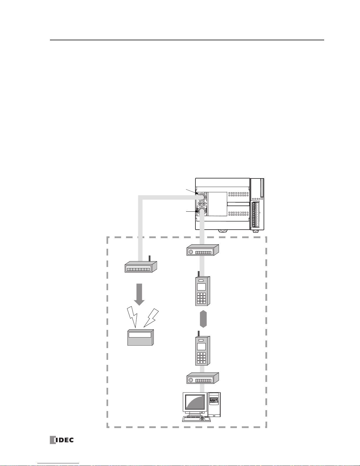
The figure below illustrates a system setup of user communication and modem communi
cation. In this example, the
operating status of a remote machine is monitored on a computer through modems connected to port 2 and the data is
transferred through port 1 to a pager transmitter using the user communication.
The same system can be set up using any slim type CPU module and
an optional RS232C communica
tion module.
For details about the user communication, see page 10-1.
For details about the modem mode, see page 21-1 (Advanced Vol.).
All-in-One Type CPU Module
Pager Transmitter
Pager
Modem
Data
Communication
Modem
Computer
Data
Tra nsm iss ion
RS232C
Communication
Adapter on
Port 2 Connector
Port 1
Phone: 800.894.0412 - Fax: 888.723.4773 - Web: www.clrwtr.com - Email: info@clrwtr.com
1: GENERAL INFORMATION
1-6 FC5A MicroSmart User’s Manual FC9Y-B1268
Computer Link System
When the MicroSmart is connected to a computer, operating status and I/O status can be monitored on the computer,
data in the CPU module can be monitored or updated, and user programs can be downloaded and uploaded. When an
optional RS485 communication adapter is installed on the port 2 connector of the all-in-one type CPU modules or when
an optional RS485 communication module is mounted with any slim type CPU modules, a maximum of 32 CPU modules
can be connected to one computer in the 1:N computer link system. FC5A-SIF4 expansion RS485 communication modules
can also be mounted to the CPU modules to add port 3 through port 7, so that the CPU modules can be added in the 1:N
computer link system.
For details about the computer link communication, see pages 4-1 (this manual) and 21-1 (Advanced Vol.).
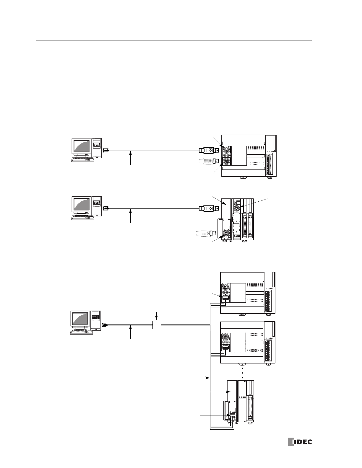
Computer Link 1:1 Communication
Slim Type CPU Module
Computer Link Cable 4C
FC2A-KC4C
3m (9.84 ft.) long
All-in-One Type CPU Module
Port 1
RS232C Communication
Adapter on Port 2 Connector
Port 2
Computer Link Cable 4C
FC2A-KC4C
3m (9.84 ft.) long
Port 1
RS232C Communication Module
Computer Link 1:N Communication
RS485 Communication Adapter
on Port 2 Connector
All-in-One Type CPU Module
RS232C Cable
HD9Z-C52
1.5m (4.92 ft.) long
RS232C/RS485 Converter
FC2A-MD1
Twisted-pair Shielded Cable
1st Unit
2nd Unit
32nd Unit
Slim Type CPU Module
Port 2
RS485 Communication Module
Phone: 800.894.0412 - Fax: 888.723.4773 - Web: www.clrwtr.com - Email: info@clrwtr.com
1: GENERAL INFORMATION
FC5A MicroSmart User’s Manual FC9Y-B1268 1-7
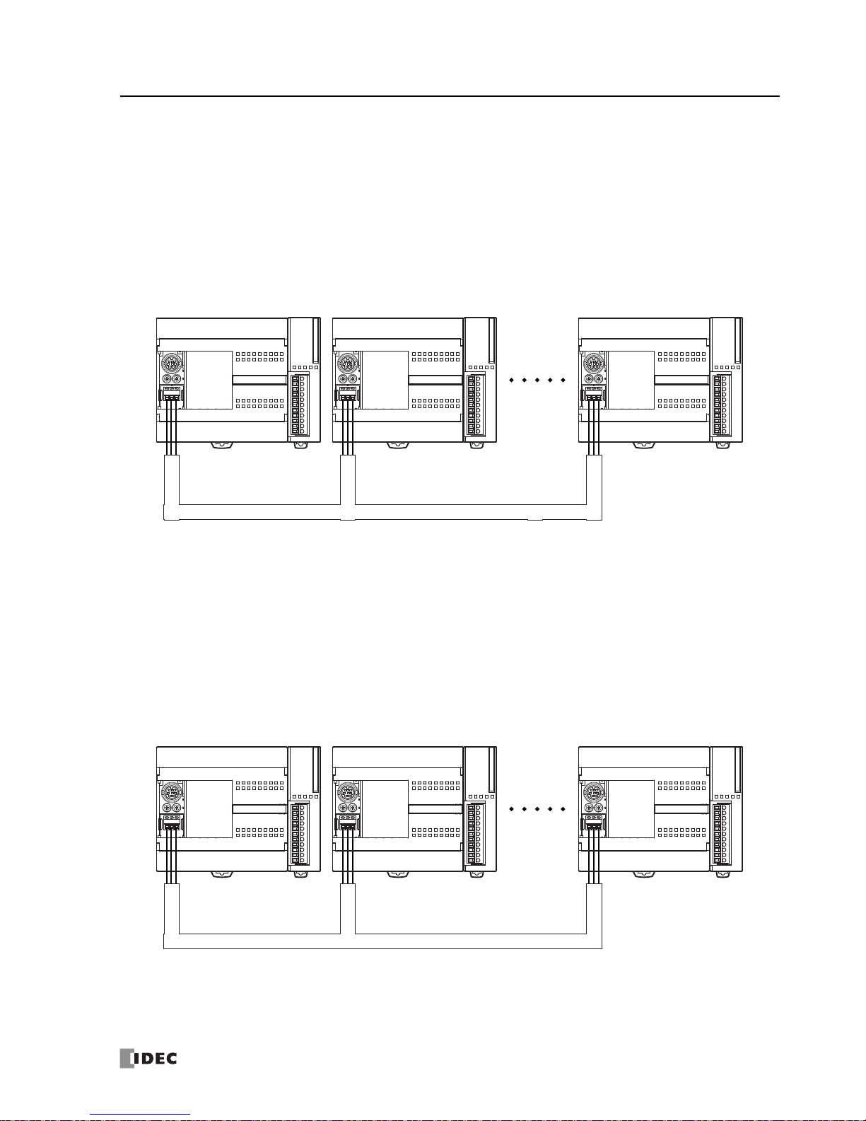
Data Link System
With an optional RS485 communication adapter installed on the port 2 connector or an FC5A-SIF4 expansion RS485 communication module mounted, one CPU module at the master station can com
municate with 31 slave stations through the
RS485 line to exchange data and perform distributed control effectively. The RS485 terminals are connected with each
other using a 2-core twisted pair cable.
The same data link system can also be set up using any slim t
ype CPU modules mounted with
RS485 communication
modules.
For details about the data link communication, see page 11-1.
Master Station Slave Station 1 Slave Station 31
Modbus Communication System
With an optional RS232C/RS485 communication adapter installed on the port 2 connector or an FC5A-SIF4 expansion
RS485 communication module mounted, any FC5A MicroSmart CPU module can be used as a Modbus master or slave
station. Using the Modbus communication, the MicroSmart CPU module can exchange data with other Modbus devices.
For details about the Modbus communication, see page 12-1.
Master Station Slave Station 1 Slave Station 31
Phone: 800.894.0412 - Fax: 888.723.4773 - Web: www.clrwtr.com - Email: info@clrwtr.com
1: GENERAL INFORMATION
1-8 FC5A MicroSmart User’s Manual FC9Y-B1268
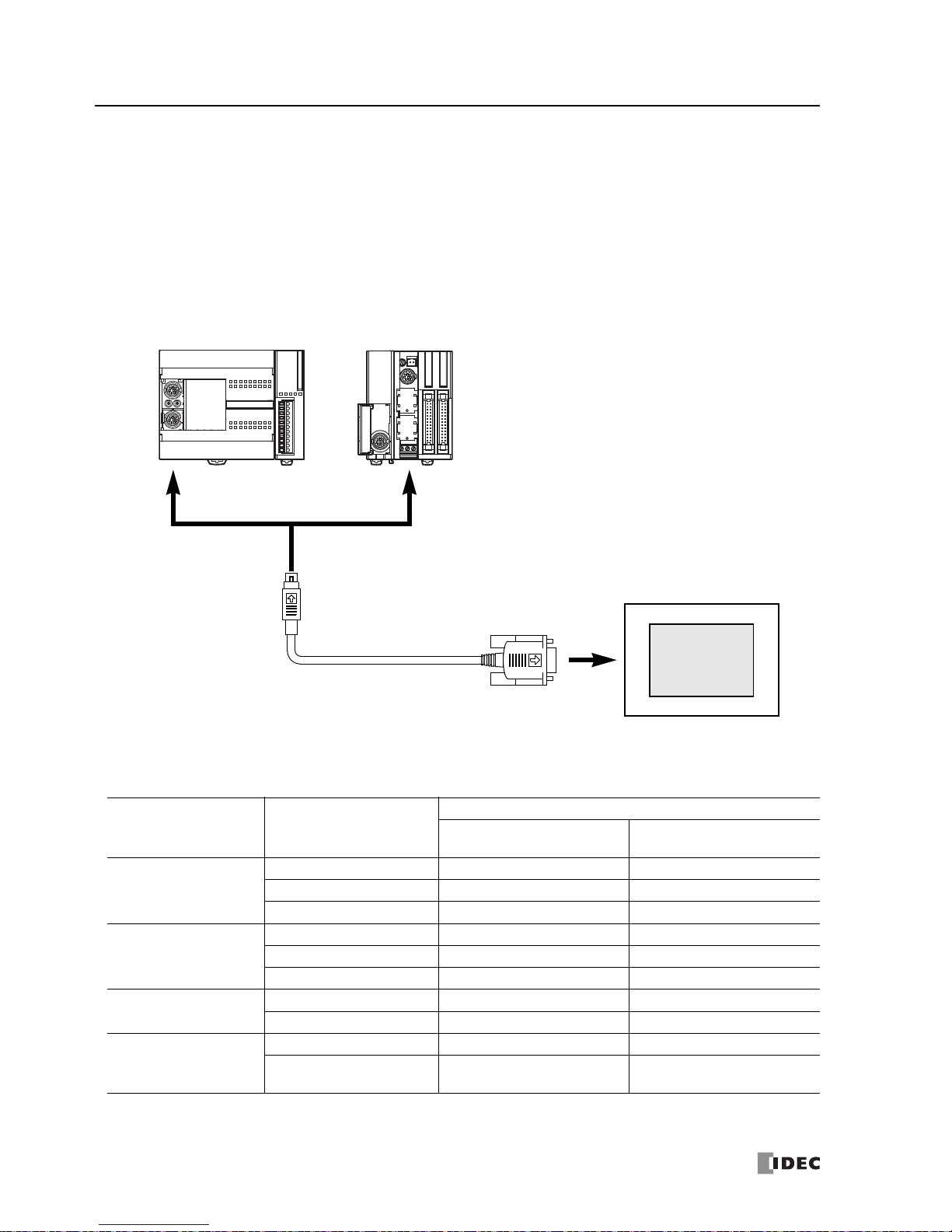
Operator Interface Communication System
The MicroSmart can communicate with IDEC’s HG series operator interfaces through RS232C or RS485 port. When using
the expansion RS232C/RS485 communication modules (FC5A-SIF2/-SIF4), the all-in-one 24-I/O CPU module, except the
12V DC type, can expand up to port 5 and the slim type CPU module can expand up to port 7. For the expansion RS232C/
RS485 communication, see page 25-1 (Advanced Vol.).
Optional cables are available for connection be
tween the MicroSmart an
d HG series operator interfaces. When installing
an optional RS232C communication adapter on the all-in-one type CPU module or an optional RS232C communication
module on the slim type CPU module, two operator interfaces can be connected to one MicroSmart CPU module.
For details about communication settings, see the
user’s manual f
or the operator interface.
HG series Operator Interface
To RS232C Port 1 or 2
O/I Communication Cable
Applicable Cables to Operator Interfaces
Operator Interface O/I Communication Cable
For Use on MicroSmart
All-in-one 24-I/O CPU Module
(except 12V DC type)
Slim CPU Module
HG1B, HG2A Series
FC4A-KC1C Port 1 to port 5 (RS232C) Port 1 to port 7 (RS232C)
HG9Z-XC183 (Note) Port 2 (RS232C) Port 2 (RS232C)
Shielded twisted-pair cable Port 2 to port 5 (RS485) Port 2 to port 7 (RS485)
HG2F, HG3F, HG4F Series
FC4A-KC2C Port 1 to port 5 (RS232C) Port 1 to port 7 (RS232C)
HG9Z-3C125 (Note) Port 2 (RS232C) Port 2 (RS232C)
Shielded twisted-pair cable Port 2 to port 5 (RS485) Port 2 to port 7 (RS485)
HG1F
FC4A-KC1C Port 1 to port 5 (RS232C) Port 1 to port 7 (RS232C)
Shielded twisted-pair cable Port 2 to port 5 (RS485) Port 2 to port 7 (RS485)
HG2G
FC4A-KP1C Port 1 to port 2 (RS232C) Port 1 to port 2 (RS232C)
Shielded twisted-pair cable
Port 3 to port 5 (RS232C)
Port 2 to port 5 (RS485)
Port 3 to port 7 (RS232C)
Port 2 to port 7 (RS485)
Note: HG
series communication cables HG9Z-XC183 and HG9Z-3C125 can
be used on port 2 only.
Phone: 800.894.0412 - Fax: 888.723.4773 - Web: www.clrwtr.com - Email: info@clrwtr.com
1: GENERAL INFORMATION
FC5A MicroSmart User’s Manual FC9Y-B1268 1-9
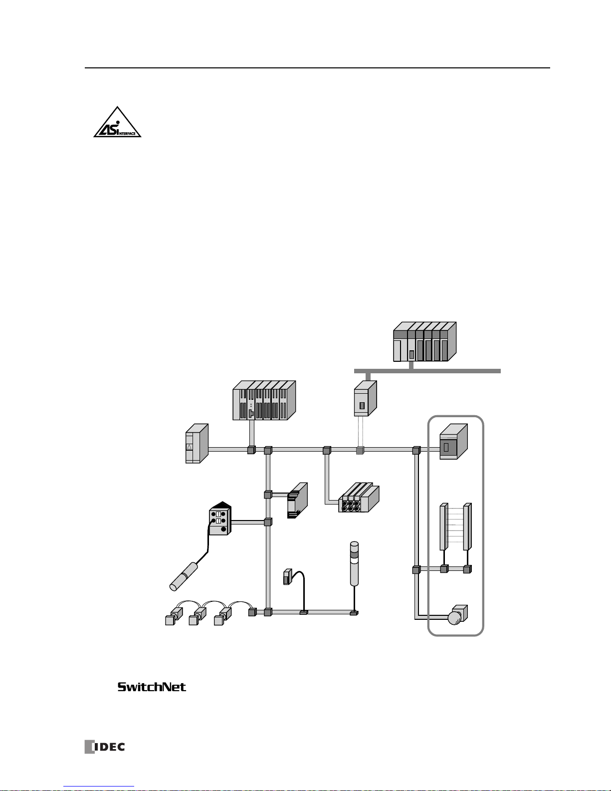
AS-Interface Network
Actuator-Sensor-Interface, abbreviated AS-Interface
The MicroSmart can be connected to the AS-Interface network using the AS-Interface master module (FC4A-AS62M).
AS-Interface is a type of field bus that is primarily intended to be used to
control sensors and actuators. AS-Interface is a
network system that is compatible with the IEC62026 standard and is not proprietary to any one manufacturer. A master
device can communicate with slave devices such as sensors, actuators, and remote I/Os, using digital and analog signals
transmitted over the AS-Interface bus.
The AS-Interface system is comprised of the following three major components:
•One master, such as the MicroSmart AS-Interface master module
•One or more slave devices, such as sensor
s, actuators, sw
itches, and indicators
•Dedicated 30V DC AS-Interface power supply (26.5 to 31.6V DC)
These components are connected using a two-core cable for both data transmission and AS-Int
erface power supply. ASInterface employs a simple yet efficient wiring system and features automatic slave address assignment function, while
installation and maintenance are also very easy.
For details about AS-Interface communication, see pages 2-78 and 24-1 (Advanced Vol.).
Light Curtain
Open Network (DeviceNet, CC-Link)
AS-Interface
Gateway
AS-Interface
Safety Monitor
AS-Interface Safety at Work
Emergency
Stop Switch
Manifold Solenoid Valve
Light Tower
(AS-Interface
Direct
Connection Type)
MicroSmart AS-Interface Master Module
PS2R AS-Interface Power Supply
SX5A AS-Interface
Communication Terminal
IP67 Outside-panel Type
SX5A AS-Interface
Communication Terminal
IP20 Inside-panel Type
SwitchNet Control Units
(AS-Interface Direct Connection Type)
Sensor
(AS-Interface Direct
Connection Type)
Sensor
The AS-Interface Safety Monitor is required
to connect safety devices, such as the light
curtain and emer gency stop switch, to the
AS-Interface line.
SwitchNet is an IDEC trademark for pushbuttons, pilot lights, and other control units capable of
direct connection to the AS-Interface. SwitchNet devices are completely compatible with ASInterface Ver. 2.1.
TM
Maximum Communication Distance
Without repeater: 100 m
With 2 repeaters: 300 m
Phone: 800.894.0412 - Fax: 888.723.4773 - Web: www.clrwtr.com - Email: info@clrwtr.com
1: GENERAL INFORMATION
1-10 FC5A MicroSmart User’s Manual FC9Y-B1268
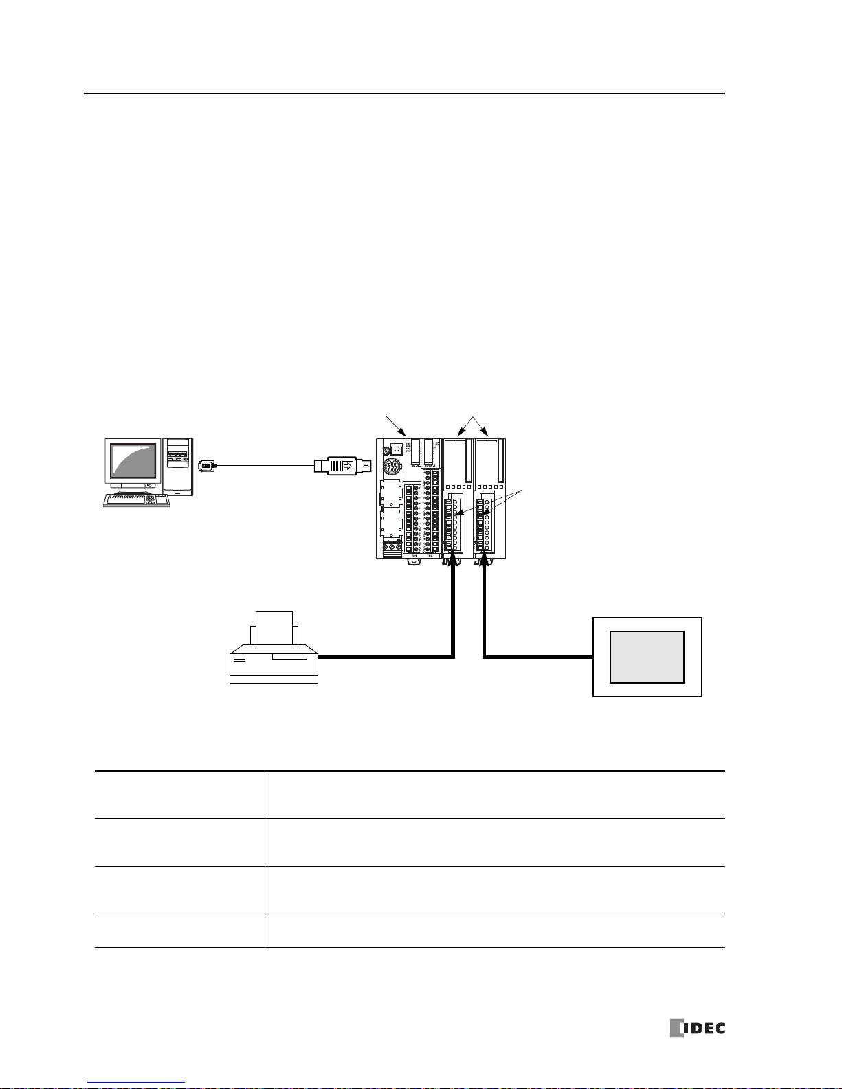
Expansion RS232C/RS485 Communication Module
The FC5A-SIF2 expansion RS232C communication module and the FC5A-SIF4 expansion RS485 communication module
are expansion modules used for the FC5A series micro programmable controller.
The expansion RS232C/RS485 communication module is mounted on the right of all-in-one 24-I/O type (ex
cept 12V DC
power type) or slim type CPU modules. All-in-one 24-I/O type CPU modules can be used with a maximum of three expansion RS232C/RS485 communication modules to expand up to five communication ports. Slim type CPU modules can be
used with a maximum of five ex
pansion RS232C/RS485 communication modules to expand up to seven communication
ports.
For example, the expansion RS232C communication module can be use
d in the follow
ing system. When the CPU module
is connected to a PC and also mounted with expansion RS232C communication modules, the PC can be used to monitor
the CPU operation while the CPU module communicates with multiple RS232C devices, such as printers, operator interfaces, and measuring instruments.
For details about these communication functions, see page 25-1 (Advanced Vol.).
System Setup Example
+
—
24VDC
PWR
SD
RD
RS232C
RS ER SD RD DR SG NC
PWR
SD
RD
RS232C
RS ER SD RD DR SG NC
Computer Link Cable 4C
FC2A-KC4C
3m (9.84 ft.) long
To P ort 3 ( RS23 2C )
Expansion Communication Port
(communication port on the RS232C
expansion communication module)
HG series Operator Interface
To Port 1 (RS232C)
CPU Module
To P ort 4 ( RS23 2C )
Expansion RS232C Communication Module
FC5A-SIF2
Printer
Features
The expansion communication module has four communica
tion functions.
Maintenance Communication
(Computer Link)
When a MicroSmart CPU module is connected to a computer, operating status and I/O status
c
an be monitor
ed on the computer, data in the CPU can be monitored or updated, and user
programs can be downloaded and uploaded. Run-time program download cannot be used.
User Communication
CPU modules can be linked to remote RS232C or RS485 devices such as computers, printers,
and
barcode reade
rs through expansion communication modules, using the user communica-
tion function.
Data Link (Note)
All MicroSmart CPU modules can set up a data link system. One CPU module at the master station can communicate with 31 slave stations through an RS485 line to exchange data and perform distributed control effectively.
Modbus Communication (Note)
All MicroSmart CPU modules can be used as a Modbus master or slave, and can be connected
to other Modbus devices
.
Note: CPU modules with system program version 220 or higher and FC5A-SIF4 are
needed to use data link or Modbus communication.
For the combination of the version numbers and supported protocols, see page A-17.
Phone: 800.894.0412 - Fax: 888.723.4773 - Web: www.clrwtr.com - Email: info@clrwtr.com
1: GENERAL INFORMATION
FC5A MicroSmart User’s Manual FC9Y-B1268 1-11
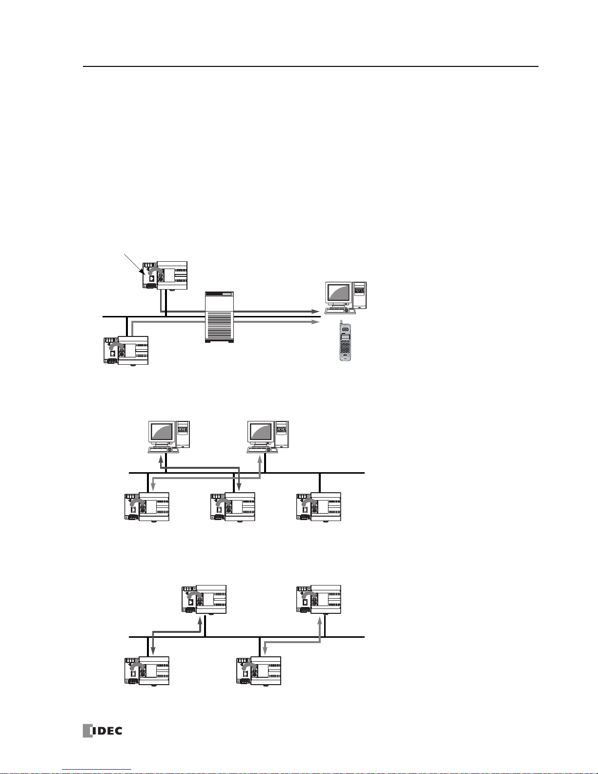
Web Server Module FC4A-SX5ES1E
A New Powerful Tool for the MicroSmart to communicate through Ethernet
• E-mail messages can be sent to PCs and mobile phones to alert a user by programming the MicroSmart to receive
inputs of abnormal machin
e conditions.
• Ethernet communication between the MicroSmart and PC enables remote maint
enance.
• User communication enables 1:1 communication between Micro
Smart CPU modules via Ethernet.
• Allows for access to data within the MicroSmart using a standard web browser.
• Connect to the MicroSmart and as well as any operator interface with an et
hernet interface and a TCP/IP client func-
tion.
For details about the web server module, see the separate brochure and user’s manual.
Sending E-mail messages
• The MicroSmart is programmed to detect
abnormal conditions of machines. When an
error occurs, an mail message is sent to the
address of PCs and mobile phones registered
within the web server module.
Web Server Module
PLC1
PLC2
E-mail Server
Internet
PC
Mobile Phone
Ethernet
Remote monitoring and control
• Operating conditions of machines can be easily monitored and changed from remote
places.
• WindLDR functions can be used on a
MicroSmart installed in remote places, for
monitoring of machines, configuration, and
to upload user programs. The MicroSmart
does not need special user programs to communicate with a PC. Also, not only WindLDR
but standard SCADA software applicable to
Ethernet enables graphical displays of monitoring and maintenance status.
PLC1
Ethernet
PLC2 PLC3
PC1 PC2
Data exchange between two MicroSmart CPU modules
• Data can be exchanged between MicroSmart
CPU modules connected with web server
modules using the user communication function.
PLC3
Ethernet
PLC4
PLC1 PLC2
Phone: 800.894.0412 - Fax: 888.723.4773 - Web: www.clrwtr.com - Email: info@clrwtr.com
1: GENERAL INFORMATION
1-12 FC5A MicroSmart User’s Manual FC9Y-B1268
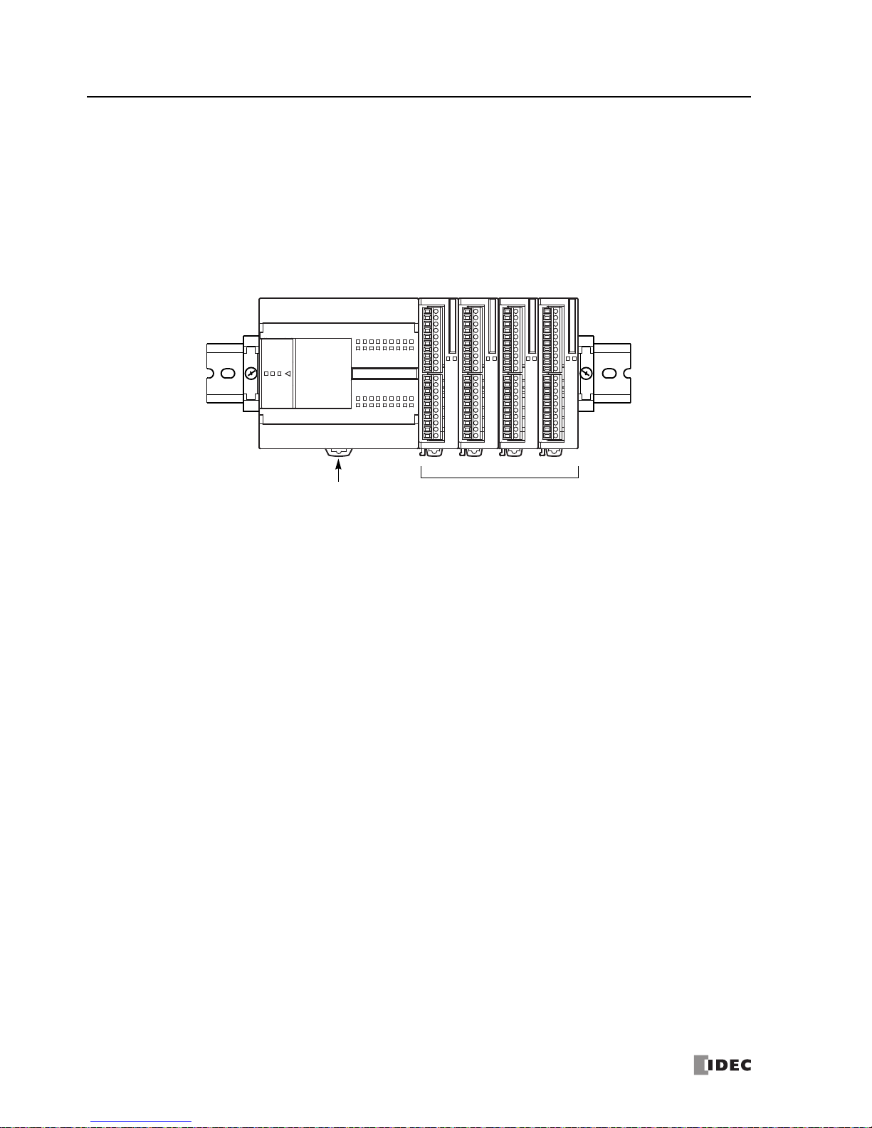
Basic System
The all-in-one 10-I/O type CPU module has 6 input terminals and 4 output terminals. The 16-I/O type CPU module has 9
input terminals and 7 output terminals. The 24-I/O type CPU module has 14 input terminals and 10 output terminals.
Only the 24-I/O type CPU module (except 12V DC power type) has an expansion connector to connect I/O modules.
When four 16-point input or output modules are connected to the 24-I/O type CPU module, the I/O points can be
expanded to a maximum of 88 points.
Any slim type CPU module can add a maximum of seven exp
ansion I/O modu
les. When using an expansion interface
module, eight more expansion I/O modules can be added. For details, see page 2-72.
4 I/O modules maximumAll-in-One 24-I/O Type CPU Module
(except 12V DC power type)
Phone: 800.894.0412 - Fax: 888.723.4773 - Web: www.clrwtr.com - Email: info@clrwtr.com
FC5A MicroSmart User’s Manual FC9Y-B1268 2-1
2: MODULE SPECIFICATIONS
Introduction
This chapter describes MicroSmart modules, parts names, and specifications of each module.
Available modules include all-in-one type and slim type CPU modules, dig
ital input modules, digital output modules,
mixed I/O modules, analog I/O modules, HMI module, HMI base module, communication adapters, communication modules, memory cartridge, and clock cartridge.
CPU Modules (All-in-One Type)
All-in-one type CPU modules are available in 10-, 16-, and 24-I/O types. The 10-I/O type has 6 input and 4 output terminals, the 16-I/O type 9 input and 7 output terminals, and the 24-I/O type 14 input and 10 ou
tput terminals. Every all-inone type CPU module has communication port 1 for RS232C communication and port 2 connector to install an optional
RS232C or RS485 communication adapter for 1:N computer link, modem communication, or data link communication.
Every all-in-one type CPU module has a cartridge connector to install an optional memory cartridge or clock cartridge.
CPU Module Type Numbers (All-in-One Type)
Power Voltage 10-I/O Type 16-I/O Type 24-I/O Type
100 -240V AC (50/60 Hz) FC5A-C10R2 FC5A-C16R2 FC5A-C24R2
24V DC FC5A-C10R2C FC5A-C16R2C FC5A-C24R2C
12V DC FC5A-C10R2D FC5A-C16R2D FC5A-C24R2D
Parts Description (All-in-One Type)
(3) Input Terminals
(5) Expansion Connector
(6) Input LED (IN)
From Left:
(7) Power LED (PWR)
(8) Run LED (RUN)
(9) Error LED (ERR)
(10) Status LED (STAT)
(11) Output LED (OUT)
(2) Sensor Power Terminals
(12) Port 1
(13) Analog Potentiometer
(14) Port 2 Connector
Bottom View
(15) Cartridge Connector
(1) Power Supply Terminals
(4) Output Terminals
(17) Hinged Lid
(16) Terminal Cover
(20) Expansion
Connector
Seal
(16) Terminal Cover
These figures illustrate the 24-I/O type
CPU module.
Functions of each part are described on
the following page.
(19) Dummy Cartridge
(18) HMI Connector Cover
Phone: 800.894.0412 - Fax: 888.723.4773 - Web: www.clrwtr.com - Email: info@clrwtr.com

2: MODULE SPECIFICATIONS
2-2 FC5A MicroSmart User’s Manual FC9Y-B1268
(1) Power Supply Terminals
Connect power supply to these terminals. Power voltage 100-240V AC or 24V DC. See page 3-18.
(2) Sensor Power Terminals (AC power type only)
For supplying power to sensors (24V DC, 250mA). These terminals can be
used for supplying pow
er to input circuits. Use the
sensor power supply only for supplying power to input devices connected to the MicroSmart.
(3) Input Terminals
For connecting input signals from input devices such as sensors,
pushbuttons, and limit switches. The input terminals
accept both sink and source DC input signals.
(4) Output Terminals
For connecting output signals to output devices such as electromechanical relays and solenoid valv
es. The internal output
re l ay i s r at ed at 24 0V A C /2 A o r 30 V DC /2A .
(5) Expansion Connector (only 24-I/O type CPU module except 12V DC powe
r type)
For connecting digital and analog I/O modules to the 24-I/O type CPU module.
(6)
Input LED (IN)
10-I/O Type
012345
IN
PRES012 3
WRUNR
R
T
A
T
OUT
16-I/O Type
0123456710
IN
PRES0123456
WRUNR
R
T
A
T
OUT
24-I/O Type
01234567101112131415
IN
PRES012345671011
WRUNR
R
T
A
T
OUT
LED Indicators
Turns on when a corresponding input is on.
(7) Power LED (PWR)
Turns on when power is supplied to the CPU module.
(8) Run LED (RUN)
Turns on when the CPU module is executing the user program.
(9) Error LED (ERR)
Turns on when an error has occurred in the CPU module.
(10) Status LED (STAT)
The status LED can be turned on or off using the user program to
indica
te a specified status.
(11) Output LED
(OUT)
Turns on when a corresponding output is on.
(12) Port 1 (RS232C)
For connecting a computer to download a user program and
monitor the PLC operation on a computer using WindLDR.
(13) Analog Potentiometer
Sets a value of 0 through 255 to a special data register. The 10- and 16-I/O type
s have one pote
ntiometer. The 24-I/O type
has two potentiometers. The analog potentiometer can be used to set a preset value for an analog timer.
(14) Port 2 Connector
For connecting an optional RS232C or RS485 communication adapter.
(15) Cartridge Connector
For connecting an optional memory cartridge or clock cartridge.
(16) Terminal Cover
For protecting the input and output terminals. When wir
ing the terminals, open the cove
rs.
(17) Hinged Lid
Open the lid to gain access to the port 1, port 2 connector, and analog potentiome
ter.
(18) HMI Connector Cover
Remove the HMI connector cover when using an optional HMI module.
(19) Dummy Cartridge
Remove the dummy cartridge when using an optional m
emory ca
rtridge or clock cartridge.
(20) Expansion Connector Seal (only 24-I/O type CPU module except 12V DC power type)
Remove the expansion connector seal when connecting an expansion module.
Phone: 800.894.0412 - Fax: 888.723.4773 - Web: www.clrwtr.com - Email: info@clrwtr.com
2: MODULE SPECIFICATIONS
FC5A MicroSmart User’s Manual FC9Y-B1268 2-3
General Specifications (All-in-One Type CPU Module)
Normal Operating Conditions
CPU
Module
AC Power Type FC5A-C10R2 FC5A-C16R2 FC5A-C24R2
24V DC Power Type FC5A-C10R2C FC5A-C16R2C FC5A-C24R2C
12V DC Power Type FC5A-C10R2D FC5A-C16R2D FC5A-C24R2D
Operating Temperature 0 to 55°C (operating ambient temperature)
Storage Temperature –25 to +70°C (no freezing)
Relative Humidity 10 to 95% (non-condensing, operating and storage humidity)
Pollution Degree 2 (IEC 60664-1)
Degree of Protection IP20 (IEC 60529)
Corrosion Immunity Atmosphere free from corrosive gases
Altitude
Operation: 0 to 2,000m (0 to 6,565 feet)
Transport: 0 to 3,000m (0 to 9,840 feet)
Vibration Resistance
When mounted on a DIN rail or panel surface:
5 to 8.4 Hz amplitude 3.5 mm, 8.4 t
o 150 Hz acceleration 9.8 m/s
2
(1G)
2 hours per axis on each of three mutually perpendicular axes (IEC 61131-2)
Shock Resistance
147 m/s
2
(15G), 11 ms duration, 3 shocks per axis on three mutually perpendicular axes (IEC
61131-2)
ESD Immunity Contact discharge: ±4 kV, Air discharge: ±8 kV (IEC 61000-4-2)
Weig ht
AC Power Type 230g 250g 305g
DC Power Type 240g 260g 310g
Power Supply (AC Power Type)
CPU Module FC5A-C10R2 FC5A-C16R2 FC5A-C24R2
Rated Power Voltage 100 to 240V AC
Allowable Voltage Range 85 to 264V AC
Rated Power Frequency 50/60 Hz (47 to 63 Hz)
Maximum Input Current 250 mA (85V AC) 300 mA (85V AC) 450 mA (85V AC)
Maximum Power Consumption
30VA (264V AC),
20VA (100V AC)
(Note 1)
31VA (264V AC),
22VA (100V AC)
(Note 1)
40VA (264V AC),
33VA (100V AC)
(Note 2)
Allowable Momentary Power
In
terruption
10 ms (at the rate
d power voltage)
Dielectric Strength
Between power and
terminals: 1,500V AC, 1 minute
Between I/O and
terminals: 1,500V AC, 1 minute
Insulation Resistance
Between power and
terminals: 10 M minimum (500V DC megger)
Between I/O and
terminals: 10 M minimum (500V DC megger)
Noise Resistance
AC power terminals: 1.5 kV, 50 ns to 1 µs
I/O terminals (coupling clamp): 1.5 kV, 50 ns to 1 µs
Inrush Current 35A maximum 35A maximum 40A maximum
Grounding Wire UL1007 AWG16
Power Supply Wire UL1015 AWG22, UL1007 AWG18
Effect of Improper Power Supply
Conn
ection
Reverse pol
arity: Normal operation (AC)
Improper voltage or frequency: Permanent damage may be caused
Improper lead connection: Permanent damage may be caused
Note 1: P
ower consumption by the CPU module, including 250mA sensor power
Note 2: Powe
r consumption by the CPU module, including 250mA sensor power, and four I/O modules
Note: The maximu
m number of relay outputs that can be turned on simultaneously is 33 point
s (AC power type CPU module) including
relay outputs on the CPU module.
Phone: 800.894.0412 - Fax: 888.723.4773 - Web: www.clrwtr.com - Email: info@clrwtr.com
2: MODULE SPECIFICATIONS
2-4 FC5A MicroSmart User’s Manual FC9Y-B1268
Power Supply (DC Power Type)
CPU Module
FC5A-C10R2C
FC5A-C10R2D
FC5A-C16R2C
FC5A-C16R2D
FC5A-C24R2C
FC5A-C24R2D
Allowable Voltage Range
24V DC power type: 20.4 to 28.8V DC
12V DC power type: 10.2 to 18.0V DC
Maximum Input Current
160 mA (24V DC)
270 mA (10.2V DC)
190 mA (24V DC)
330 mA (10.2V DC)
360 mA (24V DC)
410 mA (10.2V DC)
Maximum Power
Co
nsumption
3.9W (24V DC type) (Not
e 1)
2.8W (12V DC type) (Note 1)
4.6W (24V DC type) (Note 1)
3.4W (12V DC type) (Note 1)
8.7W (24V DC type) (Note 2)
4.2W (12V DC type) (Note 1)
Allowable Momentary
Power Interruption
10 m
s (at the rated power voltage)
Dielectric Strength
Between power and
terminals: 1,500V AC, 1 minute
Between I/O and terminals: 1,500V AC, 1 minute
Insulation Resistance
Between power and
terminals: 10 M minimum (500V DC megger)
Between I/O and terminals: 10 M minimum (500V DC megger)
Noise Resistance
IEC61131-2 Zone A compliant (reference values by noise simulator)
DC power terminals: 1.0 kV, 50 ns to 1 µs
I/O terminals (coupling clamp): 1.5 kV, 50 ns to 1 µs
Inrush Current
35A max. (24V DC type)
20A max. (12V DC type)
35A max. (24V DC type)
20A max. (12V DC type)
40A max. (24V DC type)
20A max. (12V DC type)
Grounding Wire UL1007 AWG16
Power Supply Wire UL1015 AWG22, UL1007 AWG18
Effect of Improper Power
Supp
ly Connection
Re
verse polarity: No operation, no damage
Improper voltage or frequency: Permanent damage may be caused
Improper lead connection: Permanent damage may be caused
Note 1: P
ower consumption by the CPU module
Note 2: Pow
er consumption by the CPU module and four I/O modules
Note: The maximum
number of relay outputs that can be turned on simultaneously is 44 points (24V DC power type CPU module)
including relay output
s on the CPU module.
Function Specifications (All-in-One Type CPU Module)
CPU Module Specifications
CPU Module
FC5A-C10R2
FC5A-C10R2C
FC5A-C10R2D
FC5A-C16R2
FC5A-C16R2C
FC5A-C16R2D
FC5A-C24R2
FC5A-C24R2C
FC5A-C24R2D
Program Capacity
13,800 bytes
(2,300 steps)
27,000 bytes
(4,500 steps)
54,000 bytes
(9,000 steps)
Expandable I/O Modules — — 4 modules (Note)
I/O Points
Input 6 9 14
Expansion: 64
(Note)
Output 4 7 10
User Program Storage EEPROM (10,000 rewriting life)
RAM Backup
Backup Duration Approx. 30 days (typical) at 25°C after backup battery fully charged
Backup Data Internal relay, shift register, counter, data register
Battery Lithium secondary battery
Charging Time Approx. 15 hours for charging from 0% to 90% of full charge
Battery Life 5 years in cycles of 9-hour charging and 15-hour discharging
Replaceability Not possible to replace battery
Control System Stored program system
Instruction Words
42 basic
103 advanced
42 basic
103 advanced
42 basic
115 advanced
Phone: 800.894.0412 - Fax: 888.723.4773 - Web: www.clrwtr.com - Email: info@clrwtr.com

2: MODULE SPECIFICATIONS
FC5A MicroSmart User’s Manual FC9Y-B1268 2-5
Note: The 12V DC power type CPU module cannot connect expansion I/O modules.
System Statuses at Stop, Reset, and Restart
Mode Output
Internal Relay, Shift Register,
Counter, Da
ta Register
Timer Current Value
Keep Type Clear Type
Run Operating Operating Operating Operating
Stop (Stop input ON) OFF Unchanged Unchanged Unchanged
Reset (Reset input ON) OFF OFF/Reset to zero OFF/Reset to zero Reset to zero
Restart Unchanged Unchanged OFF/Reset to zero Reset to preset
Processing
Time
Basic instruction 1.16 ms (1000
steps) See page A-1.
END processing
0.64 ms (not including expansion I/O service, clock function processing, data link processing, and interrupt processing) See page A-5.
Internal Relay 2048
Shift Register 128
Timer 256 (1-sec, 100-ms, 10-ms, 1-ms)
Counter 256 (adding, dual pulse reversible, up/down selection reversible)
Data Register 2,000
Input Filter Without filter, 3 to 15 ms (selectable in increments of 1 ms)
Catch Input
Interrupt Input
Four inputs (I2 through I5) can be designated as catch inputs or interrupt inputs
Minimum turn on pulse width: 40 µs maximum
Minimum turn off pulse width: 150 µs maximum
Self-diagnostic Function
Power failure, watchdog timer, data link connection, user program EEPR
OM sum check,
timer/counter preset value sum check, user program RAM sum check, keep data, user
program syntax, user program writing, CPU module, clock IC, I/O bus initialize, user program execution
Start/Stop Method
Turning power on and off
Start/stop command in WindLDR
Turning start control special internal relay M8000 on and off
Tur ni ng d es ignated st op or
reset input of
f and on
High-speed Counter
Total 4 points
Single/two-phase selectable: 50 kHz (1 point)
Single-phase: 5 kHz (3 points)
Counting range: 0 to 65535 (16 bits)
Operation mode: Rotary encoder mode and adding counter mode
Analog Potentiometer
1 point 1 point 2 points
Data range: 0 to 255
Sensor Power Supply
(AC power type only)
Output voltage/current: 24V DC (+10% to –15%), 250 mA
Overload detection: Not available
Isolation: Isolated from the int
ernal circuit
Communica
tion Port
Port 1 (RS232C)
Port 2 connector
Cartridge Connector 1 point for connecting a memory cartridge (32KB or 64KB) or a clock cartridge
CPU Module
FC5A-C10R2
FC5A-C10R2C
FC5A-C10R2D
FC5A-C16R2
FC5A-C16R2C
FC5A-C16R2D
FC5A-C24R2
FC5A-C24R2C
FC5A-C24R2D
Phone: 800.894.0412 - Fax: 888.723.4773 - Web: www.clrwtr.com - Email: info@clrwtr.com

2: MODULE SPECIFICATIONS
2-6 FC5A MicroSmart User’s Manual FC9Y-B1268
Communication Function
Communication Port Port 1 Port 2
Communication Adapter — FC4A-PC1 FC4A-PC2 FC4A-PC3
Standards EIA RS232C EIA RS232C EIA RS485 EIA RS485
Maximum Baud Rate 57,600 bps 57,600 bps 57,600 bps 57,600 bps
Maintenance Communication
(Computer Link)
Possible Possible Possible Possible
User Communication Possible Possible — Possible
Modem Communication — Possible — —
Data Link Communication — — —
Possible
(31 slaves max.)
Modbus Communication — Possible (Note 1) — Possible
Maximum Cable Length
Special cable
(Note 2)
Special cable
(Note 2)
Special cable
(Note 2)
200m (Note 3)
Isolation between Internal Circuit
an
d Communication
Port
Not isolated Not isolated Not isolated Not isolated
Note 1: 1:1 Modbus communication only
Note 2: For spec
ial cables, see page A-12.
Note 3: R
ecommended cable for RS485: Twisted-pair shielded cable with a minimum core wire of 0.3 mm
2
.
Conductor resistance 85 /km maximum, shield resistance 20 /km maximum.
Memory Cartridge (Option)
Memory Type EEPROM
Accessible Memory Capacity
32 KB, 64 KB, 128 KB
The maximum program capacity depends on the CPU module.
When using the 32 KB memory cartridge on the 24-I/O type CPU module, the maximum
program capacity
is limited to 30,000 bytes.
Hardware for Storing Data CPU module
Software for Storing Data WindLDR
Quantity of Stored Programs One user program can be stored on one memory cartridge.
Program Execution Priority
When a memory cartridge is installed, the user program on the memory cartridge is executed.
User programs can be downloaded from the memory cartridge to the CPU module.
User programs can also be uploaded to the memory cartridge from upgraded CPU modules
w
ith system program version 200 or higher.
Clock Cartridge (Option)
Accuracy ±30 sec/month (typical) at 25°C
Backup Duration Approx. 30 days (typical) at 25°C after backup battery fully charged
Battery Lithium secondary battery
Charging Time Approx. 10 hours for charging from 0% to 90% of full charge
Battery Life Approx. 100 recharge cycles after discha
rging down t
o 10% of full charge
Replaceability Not possible to replace battery
Phone: 800.894.0412 - Fax: 888.723.4773 - Web: www.clrwtr.com - Email: info@clrwtr.com

2: MODULE SPECIFICATIONS
FC5A MicroSmart User’s Manual FC9Y-B1268 2-7
DC Input Specifications (All-in-One Type CPU Module: AC power and 24V DC power)
CPU Module
FC5A-C10R2
FC5A-C10R2C
FC5A-C16R2
FC5A-C16R2C
FC5A-C24R2
FC5A-C24R2C
Input Points and Common Line
6 points
in 1 common line
9 points
in 1 common line
14 points
in 1 common line
Termi nal Arra n gemen t See CPU Module Terminal Arrangement on pages 2-10 and 2-11.
Rated Input Voltage 24V DC sink/source input signal
Input Voltage Range 20.4 to 28.8V DC
Rated Input Current
I0 and I1: 6.4 mA/point (24V DC)
I2 to I7, I10 to I15: 7 mA/point (24V DC)
Input Impedance
I0 and I1: 3.7 k
I2 to I7, I10 to I15: 3.4 k
Turn O N T ime
I0 and I1: 2 µs + filter value
I2 to I5: 35 µs + filter value
I6, I7, I10 to I15: 40 µs + filter value
Turn O FF T ime
I0 and I1: 16 µs + filter value
I2 to I5: 150 µs + filter value
I6, I7, I10 to I15: 150 µs + filter value
Isolation
Between input terminals: Not isolated
Internal circuit: Photocoupler isolated
Input Type Type 1 (IEC 61131-2)
External Load for I/O Interconnection Not needed
Signal Determination Method Static
Effect of Improper Input Connection
Both sinking and sourcing input signals can be
connected. If any input exceeding
the rated value is applied, permanent damage may be caused.
Cable Length 3m (9.84 ft.) in compliance with electromagnetic immunity
Input Operating Range Input Internal Circuit
Input Voltage (V DC)
28.8
0
100
I/O Simultaneous ON Ratio (%)
26.4
When using at 45°C, all I/Os can be
turned on simultaneously at input voltage 28.8V DC as indicated with line (2).
When using the FC5A-C10R2/C, all
I/Os can be turned on simultaneously at
55°C, input voltage 28.8V DC.
For other possible mounting directions,
see page 3-14.
(2) 45°C
(1) 55°C
700
I/O Usage Limits
When using the FC5A-C16R2/C or FC5A-C24R2/C at an ambient temperature of
55°C in the normal mounting direction, limit the inputs and outputs, respectively,
which turn on simultaneously along line (1).
Input
Internal Circuit
COM
3.3 k
Inputs I0 and I1
Inputs I2 to I15
3.3 k
Internal Circuit
Input
COM
The input operating range of Type 1 (IEC
61131-2) input modules is shown below:
Inputs I2 to I15
Tran sit io n
OFF Area
Input Voltage (V DC)
28.8
15
5
0
0.9 7.9
Input Current (mA)
ON Area
Area
6.43.7
24
Inputs I0 and I1
Tran sit io n
OFF Area
Input Voltage (V DC)
28.8
15
5
0
1.2 8.4
Input Current (mA)
ON Area
Area
74.2
24
Phone: 800.894.0412 - Fax: 888.723.4773 - Web: www.clrwtr.com - Email: info@clrwtr.com

2: MODULE SPECIFICATIONS
2-8 FC5A MicroSmart User’s Manual FC9Y-B1268
DC Input Specifications (All-in-One Type CPU Module: 12V DC power)
CPU Module FC5A-C10R2D FC5A-C16R2D FC5A-C24R2D
Input Points and Common Line
6 points
in 1 common line
9 points
in 1 common line
14 points
in 1 common line
Terminal Arrangement See CPU Module Terminal Arrangement on page 2-12.
Rated Input Voltage 12V DC sink/source input signal
Input Voltage Range 10.2 to 18.0V DC
Rated Input Current
I0 and I1: 6 mA/point (12V DC)
I2 to I7, I10 to I15: 6 mA/point (12V DC)
Input Impedance
I0 and I1: 1.8 k
I2 to I7, I10 to I15: 2.0 k
Turn O N T ime
I0 and I1: 2 µs + filter value
I2 to I5: 35 µs + filter value
I6, I7, I10 to I15: 40 µs + filter value
Turn OFF Time
I0 and I1: 16 µs + filter value
I2 to I5: 150 µs + filter value
I6, I7, I10 to I15: 150 µs + filter value
Isolation
Between input terminals: Not isolated
Internal circuit: Photocoupler isolated
Input Type Type 1 (IEC 61131-2)
External Load for I/O Interconnection Not needed
Signal Determination Method Static
Effect of Improper Input Connection
Both sinking and sourcing input signals can be connected. If any input exceeding
th
e rated val
ue is applied, permanent damage may be caused.
Cable Length 3m (9.84 ft.) in compliance wi
th electromagnetic immunity
Input Operating Range Input Internal Circuit
Input
Internal Circuit
COM
2.0 k
Input
Internal Circuit
COM
1.8 k
Inputs I0 and I1
Inputs I2 to I15
The input operating range of Type 1 (IEC 61131-2) input
modules is shown below:
Inputs I2 to I15
Tra nsi ti on
OFF Area
Input Voltage (V DC)
18
5.6
2.4
0
0.3 8.5
Input Current (mA)
ON Area
Area
5.21.7
12
Inputs I0 and I1
Tra nsi ti on
OFF Area
Input Voltage (V DC)
18
5.6
2.4
0
0.8 8.4
Input Current (mA)
ON Area
Area
5.52.3
12
Phone: 800.894.0412 - Fax: 888.723.4773 - Web: www.clrwtr.com - Email: info@clrwtr.com

2: MODULE SPECIFICATIONS
FC5A MicroSmart User’s Manual FC9Y-B1268 2-9
Relay Output Specifications (All-in-One Type CPU Module)
CPU Module
FC5A-C10R2
FC5A-C10R2C
FC5A-C10R2D
FC5A-C16R2
FC5A-C16R2C
FC5A-C16R2D
FC5A-C24R2
FC5A-C24R2C
FC5A-C24R2D
No. of Outputs 4 points 7 points 10 points
Output Points per Common Line
COM0 3 NO contacts 4 NO contacts 4 NO contacts
COM1 1 NO contact 2 NO contacts 4 NO contacts
COM2 — 1 NO contact 1 NO contact
COM3 — — 1 NO contact
Termi nal Arra n gemen t See CPU Module Terminal Arrangement on pages 2-10 and 2-11.
Maximum Load Current
(resistive/inductive load)
2A per point
8A per common line
Minimum Switching Load 1 mA/5V DC (reference value)
Initial Contact Resistance 30 m maximum
Electrical Life 100,000 operations minimum (rated load 1,800 operations/hour)
Mechanical Life 20,000,000 operations minimum (no load 18,000 operations/hour)
Rated Load
240V AC/2A (resistive load, inductive load cos ø = 0.4)
30V DC/2A (resistive load, inductive load L/R = 7 ms)
Dielectric Strength
Between output and
or terminals: 1,500V AC, 1 minute
Between output terminal and internal circuit: 1,500V AC, 1 minute
Between output terminals (COMs): 1,500V AC, 1 minute
Contact Protection Circuit for Relay Output See page 3-17.
Output Delay
Command
Output Relay Status
OFF delay: 10 ms maximum
Chatter: 6 ms maximum
ON delay: 6 ms maximum
ON
OFF
ON
OFF
Phone: 800.894.0412 - Fax: 888.723.4773 - Web: www.clrwtr.com - Email: info@clrwtr.com

2: MODULE SPECIFICATIONS
2-10 FC5A MicroSmart User’s Manual FC9Y-B1268
CPU Module Terminal Arrangement (All-in-One Type)
The input and output terminal arrangements of the all-in-one type CPU modules are shown below.
AC Power Type CPU Module
FC5A-C10R2
LN
100-240VAC Ry.OUT Ry.OUT
COM0 COM1 30 1 2
+24V 0V
DC OUT COM
DC IN0 1 2 3 4 5
Sensor Power Terminals
Input Terminals
AC Power Terminals
Output Terminals
FC5A-C16R2
+24V 0V 10
DC OUT COM
DC IN0 1 2 3 4 5 6 7
LN
100-240VAC Ry.OUT
COM0
Ry.OUT
COM1 4 5
Ry.OUT
COM2 60 1 2 3
Sensor Power Terminals
Input Terminals
AC Power Terminals
Output Terminals
FC5A-C24R2
+24V 0V 10 11 12 13 14 15
DC OUT COM
DC IN0 1 2 3 4 5 6 7
LN
100-240VAC Ry.OUT
COM0
Ry.OUT
COM1
Ry.OUT
COM3 11
Ry.OUT
COM2 100 1 2 3 4 5 6 7
Sensor Power Terminals
Input Terminals
AC Power Terminals
Output Terminals
Phone: 800.894.0412 - Fax: 888.723.4773 - Web: www.clrwtr.com - Email: info@clrwtr.com

24V DC Power Type CPU Module
FC5A-C10R2C
Ry.OUT Ry.OUT
COM0 COM1 30 1 2
COM
DC IN0 1 2 3 4 5
+–
24VDC
Input Terminals
DC Power Terminals
Output Terminals
FC5A-C16R2C
10
COM
DC IN0 1 2 3 4 5 6 7
Ry.OUT
COM0
Ry.OUT
COM1 4 5
Ry.OUT
COM2 60 1 2 3
+–
24VDC
Input Terminals
DC Power Terminals
Output Terminals
FC5A-C24R2C
10 11 12 13 14 15
COM
DC IN0 1 2 3 4 5 6 7
Ry.OUT
COM0
Ry.OUT
COM1
Ry.OUT
COM3 11
Ry.OUT
COM2 100 1 2 3 4 5 6 7
+–
24VDC
Input Terminals
DC Power Terminals
Output Terminals
2: MODULE SPECIFICATIONS
FC5A MicroSmart User’s Manual FC9Y-B1268 2-11
Phone: 800.894.0412 - Fax: 888.723.4773 - Web: www.clrwtr.com - Email: info@clrwtr.com

12V DC Power Type CPU Module
FC5A-C10R2D
Ry.OUT Ry.OUT
COM0 COM1 30 1 2
COM
DC IN
ONLY
12VDC 0 1 2 3 4 5
+–
12VDC
Input Terminals
DC Power Terminals
Output Terminals
FC5A-C16R2D
10
COM
DC IN
ONLY
12VDC 0 1 2 3 4 5 6 7
Ry.OUT
COM0
Ry.OUT
COM1 4 5
Ry.OUT
COM2 60 1 2 3
+–
12VDC
Input Terminals
DC Power Terminals
Output Terminals
FC5A-C24R2D
10 11 12 13 14 15
COM
DC IN
ONLY
12VDC 0 1 2 3 4 5 6 7
Ry.OUT
COM0
Ry.OUT
COM1
Ry.OUT
COM3 11
Ry.OUT
COM2 100 1 2 3 4 5 6 7
+–
12VDC
Input Terminals
DC Power Terminals
Output Terminals
2: MODULE SPECIFICATIONS
2-12 FC5A MicroSmart User’s Manual FC9Y-B1268
Phone: 800.894.0412 - Fax: 888.723.4773 - Web: www.clrwtr.com - Email: info@clrwtr.com

2: MODULE SPECIFICATIONS
FC5A MicroSmart User’s Manual FC9Y-B1268 2-13
I/O Wiring Diagrams (All-in-One Type CPU Module)
The input and output wiring examples of the CPU modules are shown below. For wiring precautions, see pages 3-15
through 3-18.
AC Power Type CPU Module 24 or 12V DC Power Type CPU Module
DC Source Input Wiring
+24V 0V
DC OUT COM
DC IN0 1 2 3 4 5
+
–
+
–
Sensor
External
Power
2-wire
Sensor
Power
DC Source Input Wiring
+
–
+
–
External
Power
2-wire
COM
DC IN0 1 2 3 4 5
Sensor
24 or 12
V DC
DC Sink Input Wiring
+24V 0V
DC OUT COM
DC IN0 1 2 3 4 5
+
–
+
–
Sensor
External
Power
2-wire
Sensor
Power
DC Sink Input Wiring
COM
DC IN0 1 2 3 4 5
+
–
+
–
External
Power
2-wire
Sensor
24 or 12
V DC
AC Power and Relay Output Wiring
LN
100-240VAC Ry.OUT Ry.OUT
COM0 COM1 30 1 2
+
–
LLL L
+
–
L
N
L
N
Fuse
Fuse
Load
DC Power and Relay Output Wiring
Ry.OUT Ry.OUT
COM0 COM1 30 1 2
+–
24VDC
+
–
LLL L
+
–
L
N
L
N
Fuse
Fuse
Load
+–
+–
12VDC
24 or 12
V DC
Phone: 800.894.0412 - Fax: 888.723.4773 - Web: www.clrwtr.com - Email: info@clrwtr.com

2: MODULE SPECIFICATIONS
2-14 FC5A MicroSmart User’s Manual FC9Y-B1268
CPU Modules (Slim Type)
Slim type CPU modules are available in 16- and 32-I/O types. The 16-I/O type has 8 input and 8 output terminals, and the
32-I/O type has 16 input and 16 output terminals. The FC5A-D16RK1 and FC5A-D16RS1 have 2 transistor outputs used for
high-speed outputs and pulse outputs in addition to 6 relay outputs. Every slim type CPU module has communication
port 1 for RS232C communication, and can mount an optional RS232C or RS485 communication module for 1:N computer link, modem communication, and data link communication. The HMI base module can also be mounted to install
a
n optional HMI module and
a communication adapter. Every slim type CPU module has two cartridge connectors to
install an optional memory cartridge and a clock cartridge.
CPU Module Type Numbers (Slim Type)
I/O Points Output Type High-speed Transistor Output (Q0 & Q1) Type No.
16 (8 in / 8 out)
Relay Output
240V AC/30V DC, 2A
Sink Output 0.3A FC5A-D16RK1
Source Output 0.3A FC5A-D16RS1
32 (16 in / 16 out)
Transistor Sink Output 0.3A FC5A-D32K3
Transistor Source Output 0.3A FC5A-D32S3
Parts Description (Slim Type)
(3) Expansion Connector
(4) Power LED (PWR)
(5) Run LED (RUN)
(6) Error LED (ERR)
(7) Status LED (STAT)
(8) Input LED (DC.IN)
(9) Output LED (Tr.OUT or Ry.OUT)
(12) Port 1
(10) Analog Potentiometer
Side View
(14) Cartridge Connector 2
(1) Power Supply Terminals (2) I/O Terminals
(16) Hinged Lid
(18) Expansion
Connector
Seal
These figures illustrate the 32-I/O type
CPU module.
Functions of each part are described on
the following page.
(17) Dummy Cartridges
(15) Communication Connector
(11) Analog Voltage Input Connector
(13) Cartridge Connector 1
Phone: 800.894.0412 - Fax: 888.723.4773 - Web: www.clrwtr.com - Email: info@clrwtr.com

2: MODULE SPECIFICATIONS
FC5A MicroSmart User’s Manual FC9Y-B1268 2-15
(1) Power Supply Terminals
Connect power supply to these terminals. Power voltage 24V DC. See page 3-19.
(2) I/O Terminals
For connecting input and output signals. The input terminals accept both sink and source 24
V DC input signals. Transistor
and relay output types are available. Transistor output type has MIL connectors and relay output type has removable screw
connectors.
(3) Expansion Connector
For connecting digital and analog I/O modules.
(4) Power LED (PWR)
LED Indicators
32-I/O Type (Transistor Output)
10
11
12
13
14
15
16
17
10
11
12
13
14
15
16
17
16-I/O Type (Relay Output)
PWR
RUN
ERR
STAT
DC.IN
6
7
0
1
Ry.OUT
2
3
4
5
Tr.
OUT
PWR
RUN
ERR
STAT
0
1
2
3
4
5
6
7
0
1
2
3
4
5
6
7
DC.IN
Tr.OU T Tr.OU T
DC.IN
6
7
0
1
2
3
4
5
Turns on when power is supplied to the CPU module.
(5) Run LED (RUN)
Turns on when the CPU module is executing the user program.
(6) Error LED (ERR)
Turns on when an error occurs in the CPU module.
(7) Status LED (STAT)
The status LED can be turned on or off using the user program to indicate
a s
pecified status.
(8) Input LED (IN)
T
urns on when a corresponding input is on.
(9) Output LED (Tr.OUT or Ry.OUT)
Turns on when a corresponding output is on.
(10) Analog Potentiometer
Sets a value of 0 through 255 to a special data register. All slim type CPU
modules have one pot
entiometer, which can be used to set a preset value
for an analog timer.
(11) Analog Voltage Input Connector
For connecting an analog voltage source
of 0 through 10V DC. The analog
voltage is con
verted to a value of 0 through 255 and stored to a special
data register.
(12) Port 1 (RS232C)
For connecting a computer to download a user program and monitor the
PL
C operation on a computer us
ing WindLDR.
(13) Cartridge Connector 1
For connecting an optional memory cartridge or clock cartridge.
(14) Cartridge Connector 2
For connecting an optional memory cartridge or clock cartridge.
(15) Communication Connector
For connecting an optional communication module or HMI base module. R
emove the connector cover
before connecting a
module.
(16) Hinged Lid
Open the lid to gain access to the port 1, cartridge connectors 1 and 2, analog potentiome
ter, and analog voltage input con-
nector.
(17) Dummy Cartridges
Remove the dummy cartridge when using an optional memory cartridge or clock cartridge.
(18) Expansion Connector Seal
Remove the expansion connector seal when connecting an expansion module.
Phone: 800.894.0412 - Fax: 888.723.4773 - Web: www.clrwtr.com - Email: info@clrwtr.com

2: MODULE SPECIFICATIONS
2-16 FC5A MicroSmart User’s Manual FC9Y-B1268
General Specifications (Slim Type CPU Module)
Normal Operating Conditions
CPU Module
FC5A-D16RK1
FC5A-D16RS1
F
C5A-D32K3
FC5A-D32S3
Operating Temperature 0 to 55°C (operating ambient temperature)
Storage Temperature –25 to +70°C
Relative Humidity 10 to 95% (non-condensing, operating and storage humidity)
Pollution Degree 2 (IEC 60664-1)
Degree of Protection IP20 (IEC 60529)
Corrosion Immunity Atmosphere free from corrosive gases
Altitude
Operation: 0 to 2,000m (0 to 6,565 feet)
Transport: 0 to 3,000m (0 to 9,840 feet)
Vibration Resistance
When mounted on a DIN rail or panel surface:
5 to 8.4 Hz amplitude 3.5 mm, 8.4 to 150 Hz acceleration 9.8 m/s
2
(1G)
2 hours per axis on each of three mutually perpendicular axes (IEC 61131-2)
Shock Resistance
147 m/s
2
(15G), 11 ms duration, 3 shocks per axis on three mutually perpendicular axes (IEC
61131-2)
ESD Immunity Contact discharge: ±4 kV, Air discharge: ±8 kV (IEC 61000-4-2)
Weig ht 230g 190g
Power Supply
Rated Power Voltage 24V DC
Allowable Voltage Range 20.4 to 26.4V DC (including ripple)
Maximum Input Current 700 mA (26.4V DC) 700 mA (26.4V DC)
Maximum Power Consumption
(Note 1, 2)
CPU module + 7 I/O modules + expansion module + 8 I/O modules
19W (26.4V DC) 19W (26.4V DC)
Allowable Momentary Power
In
terruption
10 ms (at 24V
DC)
Dielectric Strength
Between power and
terminals: 500V AC, 1 minute
Between I/O and
terminals: 500V AC, 1 minute
Insulation Resistance
Between power and
terminals: 10 M minimum (500V DC megger)
Between I/O and
terminals: 10 M minimum (500V DC megger)
Noise Resistance
DC power terminals: 1.0 kV, 50 ns to 1 µs
I/O terminals (coupling clamp): 1.5 kV, 50 ns to 1 µs
Inrush Current 50A maximum (24V DC)
Grounding Wire UL1015 AWG22, UL1007 AWG18
Power Supply Wire UL1015 AWG22, UL1007 AWG18
Effect of Improper Power Supply
Co
nnection
Rever
se polarity: No operation, no damage
Improper voltage or frequency: Permanent damage may be caused
Improper lead connection: Permanent damage may be caused
Note 1: Among relay outputs on the CPU module and relay output modules connected to the CPU module, a maximum of 54 points
can be turned on simulta
neously. Among relay outputs connected beyond the expansion module, a maximum of 54 points can be
turned on simultaneously. Relay outputs exceeding these limits may not turn on correctly.
Note 2: Maximum power consumption for individual CPU module is 3.0W (125 mA at 24V
DC) for FC5A-D16RK1/RS1 and 3.4W
(140 mA at 24V DC) for FC5A-D32K3/S3.
Phone: 800.894.0412 - Fax: 888.723.4773 - Web: www.clrwtr.com - Email: info@clrwtr.com

2: MODULE SPECIFICATIONS
FC5A MicroSmart User’s Manual FC9Y-B1268 2-17
Function Specifications (Slim Type CPU Module)
CPU Module Specifications
CPU Module
FC5A-D16RK1
FC5A-D16RS1
FC5A
-D32K3
FC5A-D32S3
Program Capacity 62,400 bytes (10,400 steps)
Expandable I/O Modules 7 modules + additional 8 modules using the expansion interface module
I/O Points
Input 8
Expansion: 224 (Note 1)
Additional: 256 (Note 2)
16
Expansion: 224 (Note 1)
Additional: 256 (Note 2)
Output 8 16
User Program Storage EEPROM (10,000 rewriting life)
RAM Backup
Backup Duration Approx. 30 days (typical) at 25°C after backup battery fully charged
Backup Data Internal relay, shift register, counter, data register, expansion data register
Battery Lithium secondary battery
Charging Time Approx. 15 hours for charging from 0% to 90% of full charge
Battery Life 5 years in cycles of 9-hour charging and 15-hour discharging
Replaceability Not possible to replace battery
Control System Stored program system
Instruction Words
42 basic
126 advanced
42 basic
130 advanced
Processing Time
Basic instruction 83 µs (1000 steps) See page A-1.
END processing
0.35 ms (not including expansion I/O service, clock f
unction processing, da
ta link pro-
cessing, and interrupt processing) See page A-5.
Internal Relay 2,048
Shift Register 256
Timer 256 (1-sec, 100-ms, 10-ms, 1-ms)
Counter 256 (adding, dual pulse reversible, up/down selection reversible)
Data Register 2,000
Expansion Data Register 6,000
Extra Data Register 40,000 (Note 3)
Input Filter Without filter, 3 to 15 ms (selectable in increments of 1 ms)
Catch Input
Interrupt Input
Four inputs (I2 through I5) can be designated as catch inputs or interrupt inputs
I2 and I5: Minimum turn on pulse width: 40 µs maximum
Minimum turn off pulse width: 150 µs maximum
I3 and I4: Minimum turn on pulse width: 5 µs maximum
Minimum turn off pulse width: 5 µs maximum
Self-diagnostic Function
Power failure, watchdog timer, data link connection, user program EEPROM sum check,
ti
mer/counter preset value sum check, user program RAM sum check, keep data, user
program syntax, user program writing, CPU module, clock IC, I/O bus initialize, user program execution
Start/Stop Method
Turning power on and off
Start/stop command in WindLDR
Turning start control special internal relay M8000 on and off
Turning designated stop or reset input off and on
High-speed Counter
Total 4 points
Single/two-phase selectable: 100 kHz (2 points
)
Single-phase: 100 kHz (2 points)
Counting range: 0 to 4,294,967,295 (32 bits)
Operation mode: Rotary encoder mode and adding counter mode
Analog Potentiometer
1 point 1 point
Data range: 0 to 255
Phone: 800.894.0412 - Fax: 888.723.4773 - Web: www.clrwtr.com - Email: info@clrwtr.com

2: MODULE SPECIFICATIONS
2-18 FC5A MicroSmart User’s Manual FC9Y-B1268
Note 1: The maximum number of outputs that can be turned on simultaneously is 54 including those on the CPU module.
Note 2: Among the additional I/O modules, the maximum number of outputs that can be turned on simultaneously is 54.
Note 3: Extra data registers D10000 through D49999 are enabled using WindLDR Function Ar
ea Settings, then run-time program
download cannot be used.
System Statuses at Stop, Reset, and Restart
Mode Output
Internal Relay, Shift Register, Counter,
Data Regist
er, Expansion DR, Extra DR
Timer Current Value
Keep Type Clear Type
Run Operating Operating Operating Operating
Stop (Stop input ON) OFF Unchanged Unchanged Unchanged
Reset (Reset input ON) OFF OFF/Reset to zero OFF/Reset to zero Reset to zero
Restart Unchanged Unchanged OFF/Reset to zero Reset to preset
Note: A
ll expansion data registers are keep types.
Communication Function
Communication Port Port 1 Port 2
Communication Adapter — FC4A-PC1 FC4A-PC2 FC4A-PC3
Communication Module — FC4A-HPC1 FC4A-HPC2 FC4A-HPC3
Standards EIA RS232C EIA RS232C EIA RS485 EIA RS485
Maximum Baud Rate 57,600 bps 57,600 bps 57,600 bps 57,600 bps
Maintenance Communication
(Computer Link)
Possible Possible Possible Possible
User Communication Possible Possible — Possible
Modem Communication — Possible — —
Data Link Communication — — —
Possible
(31 slaves max.)
Modbus Communication — Possible (Note 1) — Possible
Maximum Cable Length
Special cable
(Note 2)
Special cable
(Note 2)
Special cable
(Note 2)
200m (Note 3)
Isolation between Internal Circuit
an
d Communication Port
Not isolated Not isolated Not isolated Not isolated
Note 1: 1
:1 Modbus communication only
Note 2: For spec
ial cables, see page A-12.
Note 3: R
ecommended cable for RS485: Twisted-pair shielded cable with a minimum core wire of 0.3 mm
2
.
Conductor resistance 85 /km maximum, shield resistance 20 /km maximum.
Analog Voltage Input
Quantity: 1 point
Input voltage range: 0 to 10V DC
Input impedance: Approx. 100 k
Data range: 0 to 255 (8 bits)
Pulse Output
2 points 3 points
Maximum frequency: 100 kHz
Communication Port
Port 1 (RS232C)
Communication connector for port 2
Cartridge Connector 2 points for connecting a memory cartridge (32KB or 64KB) and a clock cartridge
Phone: 800.894.0412 - Fax: 888.723.4773 - Web: www.clrwtr.com - Email: info@clrwtr.com

2: MODULE SPECIFICATIONS
FC5A MicroSmart User’s Manual FC9Y-B1268 2-19
Memory Cartridge (Option)
Memory Type EEPROM
Accessible Memory Capacity
32 KB, 64 KB, 128 KB
The maximum program capacity depends on the CPU module.
When using the 32 KB memory cartridge on the slim type CPU module, the maximum program capacity is limited to 30,000 bytes.
Hardware for Storing Data CPU module
Software for Storing Data WindLDR
Quantity of Stored Programs One user program can be stored on one memory cartridge.
Program Execution Priority
When a memory cartridge is installed, the user program on the memory cartr
idge is exe-
cuted.
User programs can be downloaded from the memory cartridge to the CPU module.
User programs can also be uploaded to the memory cartridge from upgraded CPU modules
with system progr
am version 200 or higher.
Clock Cartridge (Option)
Accuracy ±30 sec/month (typical) at 25°C
Backup Duration Approx. 30 days (typical) at 25°C after backup battery fully charged
Battery Lithium secondary battery
Charging Time Approx. 10 hours for charging from 0% to 90% of full charge
Battery Life Approx. 100 recharge cycles after discharging down to 10% of full charge
Replaceability Not possible to replace battery
Phone: 800.894.0412 - Fax: 888.723.4773 - Web: www.clrwtr.com - Email: info@clrwtr.com

2: MODULE SPECIFICATIONS
2-20 FC5A MicroSmart User’s Manual FC9Y-B1268
DC Input Specifications (Slim Type CPU Module)
CPU Module
FC5A-D16RK1
FC5A-D16RS1
FC5A-D32K3
F
C5A-D32S3
Input Points and Common Lines 8 points in 1 common line 16 points in 2 common lines
Terminal Arrangement See CPU Module Terminal Arrangement on pages 2-23 through 2-25.
Rated Input Voltage 24V DC sink/source input signal
Input Voltage Range 20.4 to 26.4V DC
Rated Input Current
I0, I1, I3, I4, I6, I7: 4.5 mA/point (24V DC)
I2, I5, I10 to I17: 7 mA/point (24V DC)
Input Impedance
I0, I1, I3, I4, I6, I7: 4.9 k
I2, I5, I10 to I17: 3.4 k
Turn O N T ime
I0, I1, I3, I4, I6, I7: 5 µs + filter value
I2, I5: 35 µs + filter value
I10 to I17: 40 µs + filter value
Turn OFF Time
I0, I1, I3, I4, I6, I7: 5 µs + filter value
I2, I5: 150 µs + filter value
I10 to I17: 150 µs + filter value
Isolation
Between input terminals: Not isolated
Internal circuit: Photocoupler isolated
Input Type Type 1 (IEC 61131)
External Load for I/O Interconnection Not needed
Signal Determination Method Static
Effect of Improper Input Connection
Both sinking and sourcing input signals can be connected. If any input exceeding
th
e rated val
ue is applied, permanent damage may be caused.
Cable Length 3m (9.84 ft.) in compliance with electromagnetic immunity
Connector on Mother Board MC1.5/13-G-3.81BK (Phoenix Contact) FL26A2MA (Oki Electric Cable)
Connector Insertion/Removal Durability 100 times minimum
Input Operating Range
The input operating range of the Type 1
(IEC 61131-2) input module is shown
below:
Inputs I0, I1, I3, I4, I6, and I7
Inputs I2, I5, and I10 to I17
Tran sit io n
OFF Area
Input Voltage (V DC)
26.4
15
5
0
1.2 7.7
Input Current (mA)
ON Area
Area
74.2
24
Tran sit io n
OFF Area
Input Voltage (V DC)
26.4
15
5
0
0.6 5.0
Input Current (mA)
ON Area
Area
4.52.6
24
Input Internal Circuit
Inputs I0, I1, I3, I4, I6, and I7
Input
Internal Circuit
COM
4.7 k
Input
Internal Circuit
COM
3.3 k
Inputs I2, I5, and I10 to I17
I/O Usage Limits
When using the FC5A-D16RK1/RS1 at an ambient temperature of 55°C in the normal
mounting direction, limit the inputs and outputs, respectively, which turn on simultaneously on each connector along line (1).
When using the FC5A-D32K3/S3, limit the inputs and outputs, respectively, which
turn on simultaneously on each connector along line (2).
Input Voltage (V DC)
26.4
0
100
I/O Simultaneous ON Ratio (%)
24.0
(3) 40°C
50
(2) 55°C
60 70 800
(1) 55°C
When using at 40°C, all I/Os on every
slim type CPU module can be turned
on simultaneously at 26.4V DC as indicated with line (3)
Phone: 800.894.0412 - Fax: 888.723.4773 - Web: www.clrwtr.com - Email: info@clrwtr.com

2: MODULE SPECIFICATIONS
FC5A MicroSmart User’s Manual FC9Y-B1268 2-21
Relay Output Specifications (Slim Type CPU Module)
CPU Module FC5A-D16RK1 FC5A-D16RS1
No. of Outputs 8 points including 2 transistor output points
Output Points per Common Line
COM0 (2 points transistor sink output) (2 points transistor source output)
COM1 3 NO contacts
COM2 2 NO contacts
COM3 1 NO contact
Termi nal Arra n gemen t See CPU Module Terminal Arrangement on page 2-23.
Maximum Load Current
2A per point
8A per common line
Minimum Switching Load 1 mA/5V DC (reference value)
Initial Contact Resistance 30 m maximum
Electrical Life 100,000 operations minimum (rated load 1,800 operations/hour)
Mechanical Life 20,000,000 operations minimum (no load 18,000 operations/hour)
Rated Load
240V AC/2A (resistive load, inductive load cos ø = 0.4)
30V DC/2A (resistive load, inductive load L/R = 7 ms)
Dielectric Strength
Between output and
terminals: 1,500V AC, 1 minute
Between output terminal and internal circuit: 1,500V AC, 1 minute
Between output terminals (COMs): 1,500V AC, 1 minute
Connector on Mother Board MC1.5/16-G-3.81BK (Phoenix Contact)
Connector Insertion/Removal Durability 100 times minimum
Contact Protection Circuit for Relay Output See page 3-17.
Output Delay
Command
Output Relay Status
OFF delay: 10 ms maximum
Chatter: 6 ms maximum
ON delay: 6 ms maximum
ON
OFF
ON
OFF
Phone: 800.894.0412 - Fax: 888.723.4773 - Web: www.clrwtr.com - Email: info@clrwtr.com

2: MODULE SPECIFICATIONS
2-22 FC5A MicroSmart User’s Manual FC9Y-B1268
Transistor Sink and Source Output Specifications (Slim Type CPU Module)
CPU Module
FC5A-D16RK1
FC5A-D16RS1
FC5A-D32K3
FC5A-D32S3
Output Type
FC5A-D16RK1: Sink output
FC5A-D16RS1: Source output
FC5A-D32K3: Sink output
FC5A-D32S3: Source output
Output Points and Common Lines 2 points in 1 common line 16 points in 2 common lines
Terminal Arrangement See CPU Module Terminal Arrangement on pages 2-23 through 2-25.
Rated Load Voltage 24V DC
Operating Load Voltage Range 20.4 to 28.8V DC
Rated Load Current 0.3A per output point
Maximum Load Current 1A per common line
Voltage Drop (ON Voltage) 1V maximum (voltage between COM and output
terminals when output is on)
Inrush Current 1A
maximum
Leakage Current 0.1 mA maximum
Clamping Voltage 39V±1V
Maximum Lamp Load 8W
Inductive Load L/R = 10 ms (28.8V DC, 1 Hz)
External Current Draw
Sink output: 100 mA maximum, 24V DC (power voltage at the +V terminal)
Source output: 100 mA maximum, 24V DC (power voltage at the –V terminal)
Isolation
Between output terminal and internal circuit: Photocoupler isolated
Between output terminals: Not isolated
Connector on Mother Board
MC1.5/16-G-3.81BK
(Phoenix Contact)
FL26A2MA
(Oki Electric Cable)
Connector Insertion/Removal Durability 100 times minimum
Output Delay
Turn O N T ime Q0 to Q1: 5 µs maximum
Q0 to Q2: 5 µs maximum
Q3 to Q17 300 µs maximum
Turn OFF Time Q0 to Q1: 5 µs maximum
Q0 to Q2: 5 µs maximum
Q3 to Q17 300 µs maximum
Output Internal Circuit
+V
Output
Internal Circuit
COM(–)
FC5A-D16RK1 and FC5A-D32K3 (Sink Output)
Internal Circuit
FC5A-D16RS1 and FC5A-D32S3 (Source Output)
COM(+)
Output
–V
Phone: 800.894.0412 - Fax: 888.723.4773 - Web: www.clrwtr.com - Email: info@clrwtr.com

2: MODULE SPECIFICATIONS
FC5A MicroSmart User’s Manual FC9Y-B1268 2-23
CPU Module Terminal Arrangement and I/O Wiring Diagrams (Slim Type)
FC5A-D16RK1 (16-I/O Relay and Transistor Sink High-speed Output Type CPU Module)
Applicable Terminal Blocks: TB1 (Left Side) FC5A-PMT13P (supplied with the
CPU module)
TB2 (Right Side) FC4A-PMTK16P (supplied with the CPU module)
+
–
24VDC
TB1 TB2
Terminal No. Input Terminal No. Output
1I0 1 Q0
2I1 2 Q1
3I2 3COM(–)
4I3 4 +V
5I4 5 NC
6I5 6 Q2
7I6 7 Q3
8I7 8 Q4
9 COM 9 COM1
10 COM 10 NC
11 COM 11 Q5
12 COM 12 Q6
13 COM 13 COM2
14 NC
15 Q7
16 COM3
Source Input Wiring
+
–
+
–
2-wire Sensor
24V DC
NPN
Sink Output Wiring
L
L
L
+–
L
LoadLFuse
AC
L
L
L
+–
AC
• Outputs Q0 and Q1 are transistor sink outputs; others are relay outputs.
• COM, COM(–), COM1, COM2, and COM3 terminals are not interconnected.
• COM terminals are interconnected.
• Connect a fuse appropriate for the load.
• For wiring precautions, see pages 3-15 through 3-19.
FC5A-D16RS1 (16-I/O Relay and Transistor Source High-speed Output Type CPU Module)
Applicable Terminal Blocks: TB1 (Left Side) FC5A-PMT13P (supplied with the
CPU module)
TB2 (Right Side) FC4A-PMTS16P (supplied with the CPU module)
+
–
24VDC
TB1 TB2
Terminal No. Input Terminal No. Output
1I0 1 Q0
2I1 2 Q1
3I2 3COM(+)
4I3 4 –V
5I4 5 NC
6I5 6 Q2
7I6 7 Q3
8I7 8 Q4
9 COM 9 COM1
10 COM 10 NC
11 COM 11 Q5
12 COM 12 Q6
13 COM 13 COM2
14 NC
15 Q7
16 COM3
Sink Input Wiring
+
–
+
–
2-wire Sensor
24V DC
PNP
Source Output Wiring
L
L
L
+–
L
LoadLFuse
AC
L
L
L
+–
AC
• Outputs Q0 and Q1 are transistor source outputs; others are relay outputs.
• COM, COM(+), COM1, COM2, and COM3 terminals are not interconnected.
• COM terminals are interconnected.
• Connect a fuse appropriate for the load.
• For wiring precautions, see pages 3-15 through 3-19.
Phone: 800.894.0412 - Fax: 888.723.4773 - Web: www.clrwtr.com - Email: info@clrwtr.com

2: MODULE SPECIFICATIONS
2-24 FC5A MicroSmart User’s Manual FC9Y-B1268
FC5A-D32K3 (32-I/O Transistor Sink Output Type CPU Module)
Applicable Connector: FC4A-PMC26P (not supplied with the CPU module)
+
–
24VDC
CN1
Terminal No. Input Terminal No. Output
26 I0 25 Q0
24 I1 23 Q1
22 I2 21 Q2
20 I3 19 Q3
18 I4 17 Q4
16 I5 15 Q5
14 I6 13 Q6
12 I7 11 Q7
10 COM 9 COM(–)
8 COM 7 COM(–)
6 COM 5 COM(–)
4COM3 +V
2COM1 +V
Source Input Wiring
+
–
+
–
2-wire Sensor
24V DC
NPN
Sink Output Wiring
L
Fuse
L
L
+–
L
L
L
L
LoadLFuse
CN2
Terminal No. Input Terminal No. Output
26 I10 25 Q10
24 I11 23 Q11
22 I12 21 Q12
20 I13 19 Q13
18 I14 17 Q14
16 I15 15 Q15
14 I16 13 Q16
12 I17 11 Q17
10 COM 9 COM(–)
8 COM 7 COM(–)
6 COM 5 COM(–)
4COM3 +V
2COM1 +V
+
–
2-wire Sensor
NPN
L
Fuse
L
L
+–
L
L
L
L
LoadLFuse
• Terminals on CN1 and CN2 are not interconnected.
• COM and COM(–) terminals are not interconnected.
• COM terminals are interconnected.
• COM(–) terminals are interconnected.
• +V terminals are interconnected.
• Connect a fuse appropriate for the load.
• For wiring precautions, see pages 3-15 through 3-19.
+
–
24V DC
Phone: 800.894.0412 - Fax: 888.723.4773 - Web: www.clrwtr.com - Email: info@clrwtr.com

2: MODULE SPECIFICATIONS
FC5A MicroSmart User’s Manual FC9Y-B1268 2-25
FC5A-D32S3 (32-I/O Transistor Source Output Type CPU Module)
Applicable Connector: FC4A-PMC26P (not supplied with the CPU module)
CN1
Terminal No. Input Terminal No. Output
26 I0 25 Q0
24 I1 23 Q1
22 I2 21 Q2
20 I3 19 Q3
18 I4 17 Q4
16 I5 15 Q5
14 I6 13 Q6
12 I7 11 Q7
10 COM 9 COM(+)
8COM7COM(+)
6COM5COM(+)
4COM3 –V
2COM1 –V
Sink Input Wiring
+
–
+
–
2-wire Sensor
24V DC
PNP
Source Output Wiring
L
Fuse
L
L
+–
L
L
L
L
LoadLFuse
CN2
Terminal No. Input Terminal No. Output
26 I10 25 Q10
24 I11 23 Q11
22 I12 21 Q12
20 I13 19 Q13
18 I14 17 Q14
16 I15 15 Q15
14 I16 13 Q16
12 I17 11 Q17
10 COM 9 COM(+)
8COM7COM(+)
6COM5COM(+)
4COM3 –V
2COM1 –V
+
–
2-wire Sensor
PNP
L
Fuse
L
L
+–
L
L
L
L
LoadLFuse
+
–
24VDC
• Terminals on CN1 and CN2 are not interconnected.
• COM and COM(+) terminals are not interconnected.
• COM terminals are interconnected.
• COM(+) terminals are interconnected.
• –V terminals are interconnected.
• Connect a fuse appropriate for the load.
• For wiring precautions, see pages 3-15 through 3-19.
+
–
24V DC
Phone: 800.894.0412 - Fax: 888.723.4773 - Web: www.clrwtr.com - Email: info@clrwtr.com

2: MODULE SPECIFICATIONS
2-26 FC5A MicroSmart User’s Manual FC9Y-B1268
CPU Modules (Slim Type Web Server)
Slim type Web server CPU modules are available in 12-I/O type and have 8 input and 4 output terminals. Slim type Web
server CPU module has built-in Ethernet port for maintenance communication, user communication, Modbus TCP communication, sending e-mail, and Web server. Slim type Web server CPU module also has built
-in USB communication port
for maintenance communication, and can mount an optional RS232C or RS485 communication module for 1:N computer
link, user communication, data link communication, and Modbus ASCII/RTU communication. The HMI base module can
also be mounted to install an optional HMI module and a communication adapter. Every slim type CPU module has two
cartridge connectors to install an optional memory cartridge and a clock cartridge.
CPU Module Type Numbers (Slim Type Web Server)
I/O Points Output Type Type No.
12 (8 in / 4 out)
Transistor Sink Output 0.3A FC5A-D12K1E
Transistor Source Output 0.3A FC5A-D12S1E
Parts Description
(1) Power Supply Terminals
(2) I/O Terminal Block
(10) USB Port
(3) Expansion Connector
(17) Cartridge Connector 2
(16) Cartridge Connector 1
(14) Analog Potenometer
(18) Communicaon Connector
(15) Analog Voltage Input Connector
(11) Ethernet Port
(12) Link LED: Orange
(4) Power LED (PWR)
(5) Run LED (RUN)
(6) Error LED (ERR)
(7) Status LED (STAT)
(9) Output LED (OUT)
(8) Input LED (IN)
(13) Network LED: Green
(21) USB Port Cover
(20) Dummy Cartridge
(22) Expansion Connector Seal
(19) Hinged Lid
Ethernet Port IndicatorsLED Indicators
LED
Phone: 800.894.0412 - Fax: 888.723.4773 - Web: www.clrwtr.com - Email: info@clrwtr.com

2: MODULE SPECIFICATIONS
FC5A MicroSmart User’s Manual FC9Y-B1268 2-27
(1) Power Supply Terminals
Connect power supply to these terminals. Power voltage 24V DC.
(2) I/O Terminal Block
For connecting input and output signals.
(3) Expansion Connector
For connecting digital and analog I/O modules.
(4) Power LED (PWR)
Turns on when power is supplied to the CPU module.
(5) Run LED (RUN)
Turns on when the CPU module is executing the user program.
(6) Error LED (ERR)
Turns on when an error occurs in the CPU module.
(7) Status LED (STAT)
The status LED can be turned on or off using the user program to indicate a specified status.
(8) Input LED (IN)
Turns on when a corresponding input is on.
(9) Output LED (OUT)
Turns on when a corresponding output is on.
(10) USB Port
For connecting a computer to download a user program and monit
or the PLC opera
tion on a computer using WindLDR. Pro-
grams written in WindLDR can be downloaded to the PLC.
(11) Ethernet Port
For connecting a LAN cable to communicate with PCs, PL
Cs, or any other network devices.
(12) Link LED:
Orange
Turns on when the CPU module is connected to another
network device using a LAN
cable.
(13) Network LED: Green
Flashes when CPU module sends or receives data from the Ethernet port.
(14) Analog Potentiometer
Sets a value of 0 through 255 to a special data register. All slim type
CPU modules have one pot
entiometer, which can be
used to set a preset value for an analog timer.
(15) Analog Voltage Input Connector
For connecting an analog voltage source of 0 through 10V DC. The a
nalog voltage is c
onverted to a value of 0 through 255
and stored to a special data register.
(16) Cartridge Connector 1
For connecting an optional memory cartridge or clock cartridge.
(17) Cartridge Connector 2
For connecting an optional memory cartridge or clock cartridge.
(18) Communication Connector
For connecting an optional communication module or HMI base mod
ule. Remove the c
onnector cover before connecting a module.
(19) Hinged Lid
Open the lid to gain access to the cartridge connectors 1 and 2, analog potentiomet
er, and analog voltage input connector.
(20) Dummy Cartridge
Remove the dummy cartridge when using an optional memory cartridge or clock cartridge.
(21) USB Port Cover
Open this cover to use the USB port.
(22) Expansion Connector Seal
Remove the expansion connector seal when connecting an expansion module.
Phone: 800.894.0412 - Fax: 888.723.4773 - Web: www.clrwtr.com - Email: info@clrwtr.com

2: MODULE SPECIFICATIONS
2-28 FC5A MicroSmart User’s Manual FC9Y-B1268
General Specifications
Normal Operating Conditions
CPU Module
FC5A-D12K1E
FC5A-D12S1E
Ope
rating Temperature 0 to 55°C (operating ambient temperature)
Storage Temperature –25 to +70°C
Relative Humidity 10 to 95% (non-condensing, operating and storage humidity)
Pollution Degree 2 (IEC 60664-1)
Degree of Protection IP20 (IEC 60529)
Corrosion Immunity Atmosphere free from corrosive gases
Altitude
Operation: 0 to 2,000m (0 to 6,565 feet)
Transport: 0 to 3,000m (0 to 9,840 feet)
Vibration Resistance
When mounted on a DIN rail or panel surface:
5 to 8.4 Hz amplitude 3.5 mm, 8.4 to 150 Hz acceleration 9.8 m/s
2
(1G)
2 hours per axis on each of three mutually perpendicular axes (IEC 61131-2)
Shock Resistance
147 m/s
2
(15G), 11 ms duration, 3 shocks per axis on three mutually perpendicular axes
(IEC 61131-2)
ESD Immunity Contact discharge: ±4 kV, Air discharge: ±8 kV (IEC 61000-4-2)
Weig ht 200g
Power Supply
Rated Power Voltage 24V DC
Allowable Voltage Range 20.4 to 26.4V DC (including ripple)
Maximum Input Current 700 mA (26.4V DC)
Maximum Power Consumption
(Note 1, 2)
CPU module + 7 I/O modules + expansion module + 8 I/O modules
19W (26.4V DC)
Allowable Momentary Power
In
terruption
10 ms (at 24V
DC)
Dielectric Strength
Between power and
terminals: 500V AC, 1 minute
Between I/O and
terminals: 500V AC, 1 minute
Insulation Resistance
Between power and
terminals: 10 M minimum (500V DC megger)
Between I/O and
terminals: 10 M minimum (500V DC megger)
Noise Resistance
DC power terminals: 1.0 kV, 50 ns to 1 µs
I/O terminals (coupling clamp): 1.5 kV, 50 ns to 1 µs
Inrush Current 50A maximum (24V DC)
Grounding Wire UL1015 AWG22, UL1007 AWG18
Power Supply Wire UL1015 AWG22, UL1007 AWG18
Effect of Improper Power Supply
Co
nnection
Rever
se polarity: No operation, no damage
Improper voltage or frequency: Permanent damage may be caused
Improper lead connection: Permanent damage may be caused
Note 1: Among relay outp
ut modules connected to the CPU module, a maximum of 54 points can be turned on simultaneously. Among
relay outputs connected beyond the expansion module, a maximum of 54 points can be turned on simultaneously. Relay outputs
exceeding these limits may not turn on correctly.
Note 2: Maximum power consumption for individual CPU module is 3.0W (125 mA at 24V DC).
Phone: 800.894.0412 - Fax: 888.723.4773 - Web: www.clrwtr.com - Email: info@clrwtr.com

2: MODULE SPECIFICATIONS
FC5A MicroSmart User’s Manual FC9Y-B1268 2-29
Function Specifications
CPU Module Specifications
CPU Module
FC5A-D12K1E
FC5A-D12S1E
Program Cap
acity 62,400/127,800 bytes (10,400/21,300 steps) (Note 1)
Expandable I/O Modules 7 modules + additional 8 modules using the expansion interface module
I/O Points
Input 8
Expansion: 224 (Note 2)
Additional: 256 (Note 3)
Output 4
User Program Storage FROM (10,000 rewriting life)
RAM Backup
Backup Duration Approx. 30 days (typical) at 25°C after backup battery fully charged
Backup Data Internal relay, shift register, counter, data register, expansion data register
Battery Lithium secondary battery
Charging Time Approx. 15 hours for charging from 0% to 90% of full charge
Battery Life 5 years in cycles of 9-hour charging and 15-hour discharging
Replaceability Not possible to replace battery
Control System Stored program system
Instruction Words
42 basic
152 advanced
Processing Time
Basic instruction 83 µs (1000 steps) See page A-1.
END processing
0.35 ms (not including expansion I/O service, clock f
unction processing, da
ta link processing, interrupt processing, USB communication processing, and Ethernet communication processing) See page A-5.
Internal Relay 2,048
Shift Register 256
Timer 256 (1-sec, 100-ms, 10-ms, 1-ms)
Counter 256 (adding, dual pulse reversible, up/down selection reversible)
Data Register 2,000
Expansion Data Register 6,000
Extra Data Register 40,000
Input Filter Without filter, 3 to 15 ms (selectable in increments of 1 ms)
Catch Input
Interrupt Input
Four inputs (I2 through I5) can be designated as catch inputs or interrupt inputs
I2 and I5: Minimum turn on pulse width: 40 µs maximum
Minimum turn off pulse width: 150 µs maximum
I3 and I4: Minimum turn on pulse width: 5 µs maximum
Minimum turn off pulse width: 5 µs maximum
Self-diagnostic Function
Power failure, watchdog timer, data link connection, user program sum check (FROM,
e
xternal EEPROM), timer/counter preset value sum check, user program RAM sum
check, keep data, user program syntax, user program writing, CPU module, clock IC, I/O
bus initialize, user program execution, memory cartridge program transfer
Start/Stop Method
Turning power on and off
Start/stop command in WindLDR
Turning start control special internal relay M8000 on and off
Turning designated stop or reset input off and on
High-speed Counter
Total 4 points
Single/two-phase selectab
le: 100 kHz (2 points
)
Single-phase: 100 kHz (2 points)
Counting range: 0 to 4,294,967,295 (32 bits)
Operation mode: Rotary encoder mode and adding counter mode
Analog Potentiometer
1 point
Data range: 0 to 255
Phone: 800.894.0412 - Fax: 888.723.4773 - Web: www.clrwtr.com - Email: info@clrwtr.com

2: MODULE SPECIFICATIONS
2-30 FC5A MicroSmart User’s Manual FC9Y-B1268
Note 1: Select program capacity of 62,400 bytes or 127,800 bytes. When 127,800 bytes is selected, the run-time program download
cannot be used.
Note 2: The maximum number of outputs that can be turned on simultaneously is 54.
Note 3: Among the additional I/O modules, the maximum number of outputs that can be turned on simultaneously is 54.
System Statuses at Stop, Reset, and Restart
Mode Output
Internal Relay, Shift Register, Counter,
Data Regist
er, Expansion DR, Extra DR
Timer Current Value
Keep Type Clear Type
Run Operating Operating Operating Operating
Stop (Stop input ON) OFF Unchanged Unchanged Unchanged
Reset (Reset input ON) OFF OFF/Reset to zero OFF/Reset to zero Reset to zero
Restart Unchanged Unchanged OFF/Reset to zero Reset to preset
Note: A
ll expansion data registers are keep types.
Communication Function
CPU Module
FC5A-D12K1E
FC5A-D12S1E
USB
Function Maintenance Communication (Note 1)
Cable USB cable from the third party (A conne
ctor to Min
i-B connector) (Note 2)
Isolation between Internal Circuit
and Communication Port
Not isolate
d
USB Type USB Mini-B
USB Standard USB 2.0
Ethernet
Electrical Characteristics IEEE 802.3 compliant
Transmission Speed 10BASE-T, 100BASE-TX
Function
Maintenance communication, user communication, Modbus TCP communication, e-mail, Web server
Recommended Cable CAT. 5 STP
Isolation between Internal Circuit
and Com
munication Port
Pulse tr
ansformer isolated
User Web Data Storage FROM
User Web Data Capacity 1MB
Port 2 (Optional) (Note 3) Possible
Note 1: T
o use the USB port, USB driver must be installed on the PC. For the procedure t
o install the driver, see Appendix of the FC5A
user’s manual Web server CPU module volume.
Note 2: A USB maintenance cable (HG9Z-XCM42) and a USB Mini-B extension cable (HG9Z
-XCE21) are available as optional accessories.
For instructions on using the USB extension cable, refer to Chapter b_3.fm "Securing USB Extension Cable Using Cable Tie" on page 3-
5.
Note 3: C
ommunication modules that can be connected to port 2 are listed in the following table.
Analog Voltage Input
Quantity: 1
point
Input voltage range: 0 to 10V DC
Input impedance: Approx. 100 k
Data range: 0 to 255 (8 bits)
Pulse Output
3 points
Maximum frequency: 100 kHz
Communication Port Communication connector for port 2
Cartridge Connector 2 points for connecting a memory cartridge (32KB, 64KB, or 128KB) and a clock cartridge
Phone: 800.894.0412 - Fax: 888.723.4773 - Web: www.clrwtr.com - Email: info@clrwtr.com

2: MODULE SPECIFICATIONS
FC5A MicroSmart User’s Manual FC9Y-B1268 2-31
Memory Cartridge (Option)
Memory Type EEPROM
Accessible Memory Capacity
32 KB, 64 KB, 128 KB
The maximum program capacity depends on the CPU module.
When using the 32 KB memory cartridge on the slim type CPU module, the maximum program capacity is limited to 30,000 bytes.
Hardware for Storing Data CPU module
Software for Storing Data WindLDR
Quantity of Stored Programs One user program can be stored on one memory cartridge. (Note 1)
Program Execution Priority
When a memory cartridge is installed, the user pr
ogram on the memory cartr
idge is exe-
cuted.
User programs can be downloaded from the memory cartridge to the CPU module.
User programs can also be uploaded to the memory cartridge from the CPU module.
Note 1: User Web data is not st
ored.
Clock Cartridge (Option)
Accuracy ±30 sec/month (typical) at 25°C
Backup Duration Approx. 30 days (typical) at 25°C after backup battery fully charged
Battery Lithium secondary battery
Charging Time Approx. 10 hours for charging from 0% to 90% of full charge
Battery Life Approx. 100 recharge cycles after discharging down to 10% of full charge
Replaceability Not possible to replace battery
Communication Function
Communication Port Port 2
Communication Adapter FC4A-PC1 FC4A-PC2 FC4A-PC3
Communication Module FC4A-HPC1 FC4A-HPC2 FC4A-HPC3
Standards EIA RS232C EIA RS485 EIA RS485
Maximum Baud Rate 115,200 bps 115,200 bps 115,200 bps
Maintenance Communication
(Computer Link)
Possible Possible Possible
User Communication Possible Possible Possible
Modem Communication — — —
Data Link Communication —
Possible
(31 slaves max.) (Note 1)
Possible
(31 slaves max.) (Note 1)
Modbus Communication Possible (Note 2) Possible Possible
Maximum Cable Length
Special cable
(Note 3)
Special cable
(Note 3)
200m (Note 4)
Isolation between Internal Circuit
an
d Communication Port
Not isolated Not isolated Not isolated
Note 1: Maximum baud rate when using data link communication is 57,600 bps.
Note 2: 1:1 Modbus commu
nication only
Not
e 3: For special cables, see page A-12.
Not
e 4: Recommended cable for RS485: Twisted-pair shielded cable with a minimum core wire of 0.3 mm
2
.
Conductor resistance 85 /km maximum, shield resistance 20 /km maximum.
Phone: 800.894.0412 - Fax: 888.723.4773 - Web: www.clrwtr.com - Email: info@clrwtr.com

2: MODULE SPECIFICATIONS
2-32 FC5A MicroSmart User’s Manual FC9Y-B1268
DC Input Specifications (Slim Type Web Server)
CPU Module
FC5A-D12K1E
FC5A-D12S1E
Input Poin
ts and Common Lines 8 points in 1 common line
Terminal Arrangement See CPU Module Terminal Arrangement on page 2-34.
Rated Input Voltage 24V DC sink/source input signal
Input Voltage Range 20.4 to 28.8V DC
Rated Input Current
I0, I1, I3, I4, I6, I7: 4.5 mA/point (24V DC)
I2, I5: 7 mA/point (24V DC)
Input Impedance
I0, I1, I3, I4, I6, I7: 4.9 k
I2, I5: 3.4 k
Turn O N T ime
I0, I1, I3, I4, I6, I7: 5 µs + filter value
I2, I5: 35 µs + filter value
Turn OFF Time
I0, I1, I3, I4, I6, I7: 5 µs + filter value
I2, I5: 150 µs + filter value
Isolation
Between input terminals: Not isolated
Internal circuit: Photocoupler isolated
Input Type Type 1 (IEC 61131-2)
External Load for I/O Interconnection Not needed
Signal Determination Method Static
Effect of Improper Input Connection
Both sinking and sourcing input signals can be connected. If any input exceeding
th
e rated value is applied, permanent damage may be caused.
Cable Length 3m (9.84 ft.) in compliance with electromagnetic immunity
Conne
ctor on Mother Board MC1.5/13-G-3.81BK (Phoenix Contact)
Connector Insertion/Removal Durability 100 times minimum
Input Operating Range
The input operating range of the Type 1
(IEC 61131-2) input module is shown
below:
Inputs I0, I1, I3, I4, I6, and I7
Inputs I2 and I5
Tran sit io n
OFF Area
Input Voltage (V DC)
26.4
15
5
0
1.2 7.7
Input Current (mA)
ON Area
Area
74.2
24
Tran sit io n
OFF Area
Input Voltage (V DC)
26.4
15
5
0
0.6 5.0
Input Current (mA)
ON Area
Area
4.52.6
24
Input Internal Circuit
Inputs I0, I1, I3, I4, I6, and I7
Inputs I2 and I5
Input
Internal Circuit
COM
4.7 k
Input
Internal Circuit
COM
3.3 k
I/O Usage Limits
When using the FC5A-D12K1E/S1E at an ambient temperature of 55°C in the normal
mounting direction, limit the inputs and outputs, respectively, which turn on simultaneously on each connector along line (1).
Input Voltage (V DC)
26.4
0
100
I/O Simultaneous ON Ratio (%)
24.0
(2) 40°C
50 60 70 800
(1) 55°C
When using at 40°C, all I/Os on every
slim type CPU module can be turned
on simultaneously at 26.4V DC as indicated with line (2)
Phone: 800.894.0412 - Fax: 888.723.4773 - Web: www.clrwtr.com - Email: info@clrwtr.com

2: MODULE SPECIFICATIONS
FC5A MicroSmart User’s Manual FC9Y-B1268 2-33
Transistor Sink and Source Output Specifications (Slim Type Web Server)
CPU Module
FC5A-D12K1E
FC5A-D12S1E
Output Type
FC5A-D12K1E: Sink output
FC5A-D12S1E: Source output
Output Points and Common Lines 4 points in 1 common line
Termi nal Arra n gemen t See CPU Module Terminal Arrangement on page 2-34.
Rated Load Voltage 24V DC
Operating Load Voltage Range 20.4 to 28.8V DC
Rated Load Current 0.3A per output point
Maximum Load Current 1A per common line
Voltage Drop (ON Vol tage) 1V maximum (voltage between COM and output terminals when output is on)
Inrush Current 1A maximum
Leakage Current 0.1 mA maximum
Clamping Voltage 39V±1V
Maximum Lamp Load 8W
Inductive Load L/R = 10 ms (28.8V DC, 1 Hz)
External Current Draw
Sink output: 100 mA maximum, 24V DC (power voltage at the +V terminal)
Source output: 100 mA maximum, 24V DC (power voltage at the –V terminal)
Isolation
Between output terminal and internal cir
cuit: Photocoupler isolated
Between output terminals: Not isolated
Connector on Mother Board
MC1.5/16-G-3.81BK
(Phoenix Contact)
Connector Insertion/Removal Durability 100 times minimum
Output Delay
Turn O N T ime
Q0 to Q2: 5 µs maximum
Q3: 300 µs maximum
Turn OFF Time
Q0 to Q2: 5 µs maximum
Q3: 300 µs maximum
Output Internal Circuit
+V
Output
Internal Circuit
COM(–)
FC5A-D12K1E (Sink Output)
COM(+)
Output
Internal Circuit
–V
FC5A-D12S1E (Source Output)
Phone: 800.894.0412 - Fax: 888.723.4773 - Web: www.clrwtr.com - Email: info@clrwtr.com

2: MODULE SPECIFICATIONS
2-34 FC5A MicroSmart User’s Manual FC9Y-B1268
CPU Module Terminal Arrangement and I/O Wiring Diagrams (Slim Type Web Server)
FC5A-D12K1E (12-I/O Transistor Sink High-speed Output Type CPU Module)
Applicable Terminal Blocks: FC5A-PMTK16EP (supplied wit
h the CPU module)
Terminal No. Input/Output
1I0
2I1
3I2
4I3
5I4
6I5
7I6
8I7
9COM
10 COM
11 Q0
12 Q1
13 Q2
14 Q3
15 COM(-)
16 +V
+
–
+
–
2-wire Sensor
24V DC
NPN
Load
L
Fuse
L
L
L
+–
• Outputs Q0 to Q3 are transistor sink outputs.
• COM and COM(–) terminals are not interconnected.
• COM terminals are interconnected.
• Connect a fuse appropriate for the load.
• For wiring precautions, see pages 3-15 through 3-19 (Basic Vol.).
FC5A-D12S1E (12-I/O Transistor Source High-speed Output Type CPU Module)
Applicable Terminal Blocks: FC5A-PMTS16EP (supplied with the CPU module)
Terminal No. Input/Output
1I0
2I1
3I2
4I3
5I4
6I5
7I6
8I7
9COM
10 COM
11 Q0
12 Q1
13 Q2
14 Q3
15 COM(+)
16 -V
+
–
+
–
2-wire Sensor
24V DC
PNP
Load
L
Fuse
L
L
L
+–
• Outputs Q0 to Q3 are transistor source outputs.
• COM and COM(+) terminals are not interconnected.
• COM terminals are interconnected.
• Connect a fuse appropriate for the load.
• For wiring precautions, see pages 3-15 through 3-19 (Basic Vol.).
Phone: 800.894.0412 - Fax: 888.723.4773 - Web: www.clrwtr.com - Email: info@clrwtr.com

2: MODULE SPECIFICATIONS
FC5A MicroSmart User’s Manual FC9Y-B1268 2-35
Input Modules
Digital input modules are available in 8-, 16-, and 32-point DC input modules and an 8-point AC input module with a
screw terminal block or plug-in connector for input wiring. All DC input modules accept both sink and source DC input
signals.
The input modules can be connected to the all-in-one 24-I/O type CPU module and all slim type CPU modules t
o expand
input terminals. The all-in-one 10- and 16-I/O type CPU modules cannot connect input modules.
Input Module Type Numbers
Module Name 8-point DC Input 16-point DC Input 32-point DC Input 8-point AC Input
Screw Terminal FC4A-N08B1 FC4A-N16B1 — FC4A-N08A11
Connector — FC4A-N16B3 FC4A-N32B3 —
Parts Description
The above figures illustrate the 8-point DC input module.
(1) Expansion Connector
(2) Module Label
(3) LED Indicator
(4) Terminal No.
(5) Cable Terminal/Connector
(1) Expansion Connector Connects to the CPU and other I/O modules.
(The all-in-one 10- and 16-I/O type CPU modules cannot be connect
ed.)
(2) Module Label Indicates the input module Type N
o. and specifications.
(3) LED Indicator Turns on when a corres
ponding input is on.
(4) Terminal No. Indicates terminal numbers.
(5) C
able Terminal/Connector Five differen
t terminal/connector styles are available for wiring.
Phone: 800.894.0412 - Fax: 888.723.4773 - Web: www.clrwtr.com - Email: info@clrwtr.com

2: MODULE SPECIFICATIONS
2-36 FC5A MicroSmart User’s Manual FC9Y-B1268
DC Input Module Specifications
Type No. FC4A-N08B1 FC4A-N16B1 FC4A-N16B3 FC4A-N32B3
Input Points and Common Lines
8 points in 1
common line
16 points in 1 common line
16 points in 1
c
ommon line
32 points in
2
common lines
Terminal Arrangement See Input Module Terminal Arrangement on pages 2-38 through 2-40.
Rated Input Voltage 24V DC sink/source input signal
Input Voltage Range 20.4 to 28.8V DC
Rated Input Current 7 mA/point (24V DC) 5 mA/point (24V DC)
Input Impedance 3.4 k 4.4 k
Turn ON Time (24V DC) 4 ms
Turn OFF Time (24V DC) 4 ms
Isolation
Between input terminals: Not isolated
Internal circuit: Photocoupler isolated
External Load for I/O Interconnection Not needed
Signal Determination Method Static
Effect of Improper Input Connection
Both sinking and sourcing input signals can be connected. If any input exceeding
the rated val
ue is applied, permanent damage may be caused.
Cable Length 3m (9.84 ft.) in compliance with electromagnetic immunity
Conne
ctor on Mother Board MC1.5/10-G-3.81BK (Phoenix Contact) FL20A2MA (Oki Electric Cable)
Connector Insertion/Removal Durability 100 times minimum
Internal Current Draw
All Inputs ON
25 mA (5V DC)
0 mA (24V DC)
40 mA (5V DC)
0 mA (24V DC)
35 mA (5V DC)
0 mA (24V DC)
65 mA (5V DC)
0 mA (24V DC)
All Inputs OFF
5 mA (5V DC)
0 mA (24V DC)
5 mA (5V DC)
0 mA (24V DC)
5 mA (5V DC)
0 mA (24V DC)
10 mA (5V DC)
0 mA (24V DC)
Weig ht 85g 100g 65g 100g
Input Internal Circuit
Input Usage Limits
When using the FC4A-N16B1 at 55°C in the normal mounting direction, limit the
inputs which turn on simultaneously along line (1). At 45°C, all inputs can be
turned on simultaneously at 28.8V DC as indicated with line (2).
When using the FC4A-N16B3 or -N32B3 at 55°C, limit the inputs which turn on
simultaneously on each connector along line (3). At 30°C, all inputs can be turned
on simultaneously at 28.8V DC as indicated with line (4).
When using the FC4A-N08B1, all inputs can be turned on simultaneously at 55°C,
input voltage 28.8V DC.
FC4A-N08B1 and FC4A-N16B1
Input
Internal Circuit
COM
3.3 k
FC4A-N16B3 and FC4A-N32B3
Input
Internal Circuit
COM
4.3 k
Input Voltage (V DC)
28.8
0
100
Input Simultaneous ON Ratio (%)
26.4
(2) 45°C
(1) 55°C
700
Input Voltage (V DC)
28.8
0
100
Input Simultaneous ON Ratio (%)
26.4
(4) 30°C
90
(3) 55°C
700
24.0
50
Input Operating Range
The input operating range of the Type 1
(IEC 61131-2) input module is shown
below:
FC4A-N16B3 and FC4A-N32B3
Tran sit io n
OFF Area
Input Voltage (V DC)
28.8
15
5
0
1.2 8.4
Input Current (mA)
ON Area
Area
7.04.2
24
FC4A-N08B1 and FC4A-N16B1
Tran sit io n
OFF Area
Input Voltage (V DC)
28.8
15
5
0
0.9 6.4
Input Current (mA)
ON Area
Area
5.33.2
24
Phone: 800.894.0412 - Fax: 888.723.4773 - Web: www.clrwtr.com - Email: info@clrwtr.com
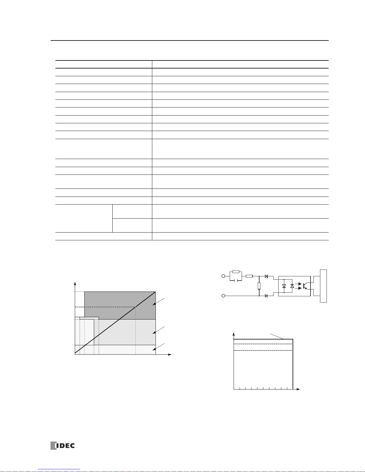
2: MODULE SPECIFICATIONS
FC5A MicroSmart User’s Manual FC9Y-B1268 2-37
AC Input Module Specifications
Type No. FC4A-N08A11
Input Points and Common Lines 8 points in 2 common lines
Termi nal Arra n gemen t See Input Module Terminal Arrangement on page 2-41.
Rated Input Voltage 100 to 120V AC (50/60 Hz)
Input Voltage Range 85 to 132V AC
Rated Input Current 17 mA/point (120V AC, 60 Hz)
Input Type AC input; Type 1, 2 (IEC 61131)
Input Impedance 0.8 k (60 Hz)
Turn O N T ime 25 ms
Turn O FF T ime 30 ms
Isolation
Between input terminals in the same common: Not isolated
Between input terminals in different commons: Isolated
Between input terminals and internal circuits: Photocoupler isolated
External Load for I/O Interconnection Not needed
Signal Determination Method Static
Effect of Improper Input Connection
If any input exceeding the rated value is
applied, pe
rmanent damage may be
caused.
Connector on Mother Board MC1.5/11-G-3.81BK (Phoenix Contact)
Connector Insertion/Removal Durability 100 times minimum
Internal Current Draw
All Inputs ON
60 mA (5V DC)
0 mA (24V DC)
All Inputs OFF
30 mA (5V DC)
0 mA (24V DC)
Weig ht 80g
Input Internal Circuit
Input Usage Limits
When using the FC4A-N08A11, all inputs can be turned
on simultaneously at 55°C, input voltage 132V AC.
FC4A-N08A11
Input
Internal Circuit
COM
480 k
220
0.33 µF
Input Voltage (V AC)
132
0
100
Input Simultaneous ON Ratio (%)
55°C
500
102
120
Input Operating Range
The input operating range of the Type 1 and 2 (IEC 61131-2) input
module is shown below:
FC4A-N08A11
74
20
0
1
Input Current (mA)
5
132
Input Voltage (V AC)
24 17
79
Tran sit ion
OFF Area
ON Area
100
13
Area
Phone: 800.894.0412 - Fax: 888.723.4773 - Web: www.clrwtr.com - Email: info@clrwtr.com

2: MODULE SPECIFICATIONS
2-38 FC5A MicroSmart User’s Manual FC9Y-B1268
DC Input Module Terminal Arrangement and Wiring Diagrams
FC4A-N08B1 (8-point DC Input Module) — Screw Terminal Type
Applicable Terminal Block: FC4A-PMT10P (supplied with the input module)
COM COM
0
1
2
3
4
5
6
7
DC.IN
01234567
Terminal No. Input
0I0
1I1
2I2
3I3
4I4
5I5
6I6
7I7
COM COM
COM COM
Source Input Wiring
Terminal No. Input
0I0
1I1
2I2
3I3
4I4
5I5
6I6
7I7
COM COM
COM COM
Sink Input Wiring
• Two COM terminals are interconnected.
• For input wiring precautions, see page 3-15.
+
–
+
–
2-wire Sensor
24V DC
NPN
+
–
+
–
2-wire Sensor
24V DC
PNP
FC4A-N16B1 (16-point DC Input Module) — Screw Terminal Type
Applicable Terminal Block: FC4A-PMT10P (supplied with the input module)
0
1
2
3
4
5
6
7
10
11
12
13
14
15
16
17
DC.IN
COM COM
10 11 12 13 14 15 16 17
0 1 2 3 4 5 6 7
COM COM
Terminal No. Input
0I0
1I1
2I2
3I3
4I4
5I5
6I6
7I7
COM COM
COM COM
10 I10
11 I11
12 I12
13 I13
14 I14
15 I15
16 I16
17 I17
COM COM
COM COM
Source Input Wiring
Terminal No. Input
0I0
1I1
2I2
3I3
4I4
5I5
6I6
7I7
COM COM
COM COM
10 I10
11 I11
12 I12
13 I13
14 I14
15 I15
16 I16
17 I17
COM COM
COM COM
Sink Input Wiring
• Four COM terminals are interconnected.
• For input wiring precautions, see page 3-15.
+
–
+
–
2-wire Sensor
24V DC
NPN
+
–
NPN
+
–
+
–
2-wire Sensor
24V DC
PNP
+
–
PNP
Phone: 800.894.0412 - Fax: 888.723.4773 - Web: www.clrwtr.com - Email: info@clrwtr.com

2: MODULE SPECIFICATIONS
FC5A MicroSmart User’s Manual FC9Y-B1268 2-39
FC4A-N16B3 (16-point DC Input Module) — Connector Type
Applicable Connector: FC4A-PMC20P (not supplied with the input module)
• Two COM terminals are interconnected.
• For input wiring precautions, see page 3-15.
Terminal No. Input Terminal No. Input
20 I0 19 I10
18 I1 17 I11
16 I2 15 I12
14 I3 13 I13
12 I4 11 I14
10 I5 9 I15
8I67I16
6I75I17
4COM3COM
2NC1NC
Source Input Wiring
+
–
+
–
2-wire Sensor
24V DC
NPN
+
–
+
–
2-wire Sensor
24V DC
NPN
Terminal No. Input Terminal No. Input
20 I0 19 I10
18 I1 17 I11
16 I2 15 I12
14 I3 13 I13
12 I4 11 I14
10 I5 9 I15
8I67I16
6I75I17
4COM3COM
2NC1NC
Sink Input Wiring
+
–
+
–
2-wire Sensor
24V DC
PNP
+
–
+
–
2-wire Sensor
24V DC
PNP
Phone: 800.894.0412 - Fax: 888.723.4773 - Web: www.clrwtr.com - Email: info@clrwtr.com

2: MODULE SPECIFICATIONS
2-40 FC5A MicroSmart User’s Manual FC9Y-B1268
FC4A-N32B3 (32-point DC Input Module) — Connector Type
Applicable Connector: FC4A-PMC20P (not supplied with the input module)
CN1
No. Input No. Input
20 I0 19 I10
18 I1 17 I11
16 I2 15 I12
14 I3 13 I13
12 I4 11 I14
10 I5 9 I15
8I67I16
6I75I17
4COM03COM0
2NC1NC
Source Input Wiring
• COM0 terminals are interconnected.
• COM1 terminals are interconnected.
• COM0 and COM1 terminals are not interconnected.
• For input wiring precautions, see page 3-15.
+
–
+
–
2-wire Sensor
24V DC
NPN
+
–
+
–
2-wire Sensor
24V DC
NPN
CN2
No. Input No. Input
20I2019I30
18I2117I31
16 I22 15 I32
14 I23 13 I33
12 I24 11 I34
10 I25 9 I35
8I267I36
6I275I37
4COM13COM1
2NC1NC
+
–
+
–
2-wire Sensor
24V DC
NPN
+
–
+
–
2-wire Sensor
24V DC
NPN
CN1
No. Input No. Input
20 I0 19 I10
18 I1 17 I11
16 I2 15 I12
14 I3 13 I13
12 I4 11 I14
10 I5 9 I15
8I67I16
6I75I17
4COM03COM0
2NC1NC
Sink Input Wiring
+
–
+
–
2-wire Sensor
24V DC
PNP
+
–
+
–
2-wire Sensor
24V DC
PNP
CN2
No. Input No. Input
20I2019I30
18I2117I31
16 I22 15 I32
14 I23 13 I33
12 I24 11 I34
10 I25 9 I35
8I267I36
6I275I37
4COM13COM1
2NC1NC
+
–
+
–
2-wire Sensor
24V DC
PNP
+
–
+
–
2-wire Sensor
24V DC
PNP
Phone: 800.894.0412 - Fax: 888.723.4773 - Web: www.clrwtr.com - Email: info@clrwtr.com

2: MODULE SPECIFICATIONS
FC5A MicroSmart User’s Manual FC9Y-B1268 2-41
AC Input Module Terminal Arrangement and Wiring Diagrams
FC4A-N08A11 (8-point AC Input Module) — Screw Terminal Type
Applicable Terminal Block: FC4A-PMT11P (supplied with the input module)
7 COM1
0
1
2
3
4
5
6
7
AC.IN
1023
COM0
NC 4 5 6
Term inal N o. Ou tp ut
0I0
1I1
2I2
3I3
COM0 COM0
NC NC
4I4
5I5
6I6
7I7
COM1 COM1
AC
AC
• Two COM terminals are not interconnected.
• For input wiring precautions, see page 3-15.
• Do not connect an external load to the input terminals.
Phone: 800.894.0412 - Fax: 888.723.4773 - Web: www.clrwtr.com - Email: info@clrwtr.com

2: MODULE SPECIFICATIONS
2-42 FC5A MicroSmart User’s Manual FC9Y-B1268
Output Modules
Digital output modules are available in 8- and 16-point relay output modules, 8-, 16- and 32-point transistor sink output
modules, and 8-, 16- and 32-point transistor source output modules with a screw terminal block or plug-in connector for
output wiring.
The output modules can be connected to the all-in-one 24-I/O type CPU module and all slim type CPU modules to e
xpand
output terminals. The all-in-one 10- and 16-I/O type CPU modules cannot connect output modules.
Output Module Type Numbers
Module Name Te rm i na l Type No.
8-point Relay Output
Removable Terminal Block
FC4A-R081
16-point Relay Output FC4A-R161
8-point Transistor Sink Output FC4A-T08K1
8-point Transistor Source Output FC4A-T08S1
16-point Transistor Sink Output
MIL Connector
FC4A-T16K3
16-point Transistor Source Output FC4A-T16S3
32-point Transistor Sink Output FC4A-T32K3
32-point Transistor Source Output FC4A-T32S3
Parts Description
The above figures illustrate the 8-point relay output module.
(1) Expansion Connector
(2) Module Label
(3) LED Indicator
(4) Terminal No.
(5) Cable Terminal/Connector
(1) Expansion Connector Connects to the CPU and other I/O modules.
(The all-in-one 10- and 16-I/O type CPU modules cannot be connected.)
(2) Module
Label Indicates the output m
odule Type No. and specifications.
(3) LED Indicator Turns on when a corresponding
output is on.
(4) Terminal No. Indicates te
rminal numbers.
(5) Cable Terminal/Connector Five differen
t terminal/connector styles are available for wiring.
Phone: 800.894.0412 - Fax: 888.723.4773 - Web: www.clrwtr.com - Email: info@clrwtr.com

2: MODULE SPECIFICATIONS
FC5A MicroSmart User’s Manual FC9Y-B1268 2-43
Relay Output Module Specifications
Type No. FC4A-R081 FC4A-R161
Output Points and Common Lines 8 NO contacts in 2 common lines 16 NO contacts in 2 common lines
Termi nal Arra n gemen t See Relay Output Module Terminal Arrangement on page 2-44.
Maximum Load Current
2A per point
7A per common line 8A per common line
Minimum Switching Load 1 mA/5V DC (reference value)
Initial Contact Resistance 30 m maximum
Electrical Life 100,000 operations minimum (rated load 1,800 operations/hour)
Mechanical Life 20,000,000 operations minimum (no load 18,000 operations/hour)
Rated Load
240V AC/2A (resistive load, inductive load cos ø = 0.4)
30V DC/2A (resistive load, inductive load L/R = 7 ms)
Dielectric Strength
Between output and
or terminals: 1,500V AC, 1 minute
Between output terminal and internal circuit: 1,500V AC, 1 minute
Between output terminals (COMs): 1,500V AC, 1 minute
Connector on Mother Board
MC1.5/11-G-3.81BK
(Phoenix Contact)
MC1.5/10-G-3.81BK
(Phoenix Contact)
Connector Insertion/Removal Durability 100 times minimum 100 times minimum
Internal Current Draw
All Outputs ON
30 mA (5V DC)
40 mA (24V DC)
45 mA (5V DC)
75 mA (24V DC)
All Outputs OFF
5 mA (5V DC)
0 mA (24V DC)
5 mA (5V DC)
0 mA (24V DC)
Internal Power Consumption
(at 24V DC while all outputs ON)
1.16W 2.10W
Weig ht 110g 145g
Contact Protection Circuit for Relay Output See page 3-17.
Note: Whe
n relay output modules are connected to the all-in-one 24-I/O type CPU module or a
ny slim type CPU module, the maxi-
mum number of relay outputs that can be turned on simultaneously, including the outputs on the CPU module, are shown below.
CPU Module Type
All-in-One 24-I/O CPU Module
Slim Type CPU Module
AC Power Type DC Power Type
Maximum Relay Outputs Turning On Simultaneously
33 44
108 total
54 (on the left of expansion interface module)
54 (on the right of expansion interface module)
Output Delay
Command
Output Relay Status
OFF delay: 10 ms maximum
Chatter: 6 ms maximum
ON delay: 6 ms maximum
ON
OFF
ON
OFF
Phone: 800.894.0412 - Fax: 888.723.4773 - Web: www.clrwtr.com - Email: info@clrwtr.com

2: MODULE SPECIFICATIONS
2-44 FC5A MicroSmart User’s Manual FC9Y-B1268
Relay Output Module Terminal Arrangement and Wiring Diagrams
FC4A-R081 (8-point Relay Output Module) — Screw Terminal Type
Applicable Terminal Block: FC4A-PMT11P (supplied with the output module)
L
7COM1
0
1
2
3
4
5
6
7
Ry.OUT
1023
COM0
NC456
Terminal No. Output
0Q0
1Q1
2Q2
3Q3
COM0 COM0
NC NC
4Q4
5Q5
6Q6
7Q7
COM1 COM1
L
Fuse
L
L
L
AC
Fuse
Fuse
DC
DC
Load
L
L
L
Fuse
+
–
AC
Fuse
Fuse
DC
DC
+
–
+
–
+
–
• COM0 and COM1 terminals are not interconnected.
• Connect a fuse appropriate for the load.
• For output wiring precautions, see page 3-16.
Fuse
FC4A-R161 (16-point Relay Output Module) — Screw Terminal Type
Applicable Terminal Block: FC4A-PMT10P (supplied with the output module)
0
1
2
3
4
5
6
7
10
11
12
13
14
15
16
17
Ry.OUT
COM1 COM1
10 11 12 13 14 15 16 17
0 1 2 3 4 5 6 7
COM0 COM0
L
Terminal No. Output
0Q0
1Q1
2Q2
3Q3
4Q4
5Q5
6Q6
7Q7
COM0 COM0
COM0 COM0
10 Q10
11 Q11
12 Q12
13 Q13
14 Q14
15 Q15
16 Q16
17 Q17
COM1 COM1
COM1 COM1
L
Fuse
+
–
L
L
L
AC
Fuse
Fuse
DC
DC
+
–
Load
L
L
L
L
L
Fuse
+
–
L
L
L
AC
Fuse
Fuse
DC
DC
+
–
L
L
L
• COM0 terminals are interconnected.
• COM1 terminals are interconnected.
• COM0 and COM1 terminals are not interconnected.
• Connect a fuse appropriate for the load.
• For output wiring precautions, see page 3-16.
Fuse
Phone: 800.894.0412 - Fax: 888.723.4773 - Web: www.clrwtr.com - Email: info@clrwtr.com

2: MODULE SPECIFICATIONS
FC5A MicroSmart User’s Manual FC9Y-B1268 2-45
Transistor Sink Output Module Specifications
Type No. FC4A-T08K1 FC4A-T16K3 FC4A-T32K3
Output Type Transistor sink output
Output Points and Common Lines
8 points
in 1 common line
16 points
in 1 common line
32 points
in 2 common lines
Termi nal Arra n gemen t
See Transistor Sink Output Module Terminal Arrangement on pages 2-46
and 2-47.
Rated Load Voltage 24V DC
Operating Load Voltage Range 20.4 to 28.8V DC
Rated Load Current 0.3A per output point 0.1A per output point
Maximum Load Current (at 28.8V DC)
0.3A per output point
3A per common line
0.1A per output point
1A per common line
Voltage Drop (ON Vol tage) 1V maximum (voltage between COM and output terminals when output is on)
Inrush Current 1A maximum
Leakage Current 0.1 mA maximum
Clamping Voltage 39V±1V
Maximum Lamp Load 8W
Inductive Load L/R = 10 ms (28.8V DC, 1 Hz)
External Current Draw 100 mA maximum, 24V DC (power voltage at the +V terminal)
Isolation
Between output terminal and internal cir
cuit: Photocoupler isola
ted
Between output terminals: Not isolated
Connector on Mother Board
MC1.5/10-G-3.81BK
(Phoenix Contact)
FL20A2MA (Oki El
ectric Cable)
Connector Insertion/Removal Durability 100 times minimum
Internal Current Draw
All Outputs ON
10 mA (5V DC)
20 mA (24V DC)
10 mA (5V DC)
40 mA (24V DC)
20 mA (5V DC)
70 mA (24V DC)
All Outputs OFF
5 mA (5V DC)
0 mA (24V DC)
5 mA (5V DC)
0 mA (24V DC)
10 mA (5V DC)
0 mA (24V DC)
Internal Power Consumption
(at 24V DC while all outputs ON)
0.55W 1.03W 1.82W
Output Delay
Turn ON time: 300 µs maximum
Turn OFF time: 300 µs maximum
Weig ht (approx.) 85g 70g 105g
Output Internal Circuit
+V
Output
Internal Circuit
COM(–)
Sink Output
Phone: 800.894.0412 - Fax: 888.723.4773 - Web: www.clrwtr.com - Email: info@clrwtr.com

2: MODULE SPECIFICATIONS
2-46 FC5A MicroSmart User’s Manual FC9Y-B1268
Transistor Sink Output Module Terminal Arrangement and Wiring Diagrams
FC4A-T08K1 (8-point Transistor Sink Output Module) — Screw Terminal Type
Applicable Terminal Block: FC4A-PMT10P (supplied with the output module)
L
Terminal No. Output
0Q0
1Q1
2Q2
3Q3
4Q4
5Q5
6Q6
7Q7
COM(–) COM(–)
+V +V
Fuse
L
L
+–
L
L
L
L
Load
L
COM(–)
+V
0
1
2
3
4
5
6
7
Tr.OUT
01234567
• Connect a fuse appropriate for the load.
• For output wiring precautions, see page 3-16.
Fuse
FC4A-T16K3 (16-point Transistor Sink Output Module) — Connector Type
Applicable Connector: FC4A-PMC20P (not supplied with
the output module)
• COM(–) terminals are interconnected.
• +V terminals are interconnected.
• Connect a fuse appropriate for the load.
• For output wiring precautions, see page 3-16.
Terminal No. Output Terminal No. Output
20 Q0 19 Q10
18 Q1 17 Q11
16 Q2 15 Q12
14 Q3 13 Q13
12 Q4 11 Q14
10 Q5 9 Q15
8Q67Q16
6Q75Q17
4COM(–)3COM(–)
2+V1+V
L
L
L
+–
L
L
L
L
LoadLFuse
L
L
L
+–
L
L
L
L
Load
L
Fuse
Phone: 800.894.0412 - Fax: 888.723.4773 - Web: www.clrwtr.com - Email: info@clrwtr.com

2: MODULE SPECIFICATIONS
FC5A MicroSmart User’s Manual FC9Y-B1268 2-47
FC4A-T32K3 (32-point Transistor Sink Output Module) — Connector Type
Applicable Connector: FC4A-PMC20P (not supplied with the output module)
• Terminals on CN1 and CN2 are not interconnected.
• COM0(–) terminals are interconnected.
• COM1(–) terminals are interconnected.
• +V0 terminals are interconnected.
• +V1 terminals are interconnected.
• Connect a fuse appropriate for the load.
• For output wiring precautions, see page 3-16.
CN1
Terminal No. Output Terminal No. Output
20 Q0 19 Q10
18 Q1 17 Q11
16 Q2 15 Q12
14 Q3 13 Q13
12 Q4 11 Q14
10 Q5 9 Q15
8Q67Q16
6Q75Q17
4COM0(–)3COM0(–)
2+V01+V0
L
L
L
+–
L
L
L
L
LoadLFuse
L
L
L
+–
L
L
L
L
Load
L
Fuse
CN2
Terminal No. Output Terminal No. Output
20Q2019Q30
18Q2117Q31
16Q2215Q32
14Q2313Q33
12Q2411Q34
10Q259Q35
8Q267Q36
6Q275Q37
4COM1(–)3COM1(–)
2+V11+V1
L
L
L
+–
L
L
L
L
LoadLFuse
L
L
L
+–
L
L
L
L
Load
L
Fuse
Phone: 800.894.0412 - Fax: 888.723.4773 - Web: www.clrwtr.com - Email: info@clrwtr.com

2: MODULE SPECIFICATIONS
2-48 FC5A MicroSmart User’s Manual FC9Y-B1268
Transistor Source Output Module Specifications
Type No. FC4A-T08S1 FC4A-T16S3 FC4A-T32S3
Output Type Transistor source output
Output Points and Common Lines
8 points
in 1 common line
16 points
in 1 common line
32 points
in 2 common lines
Terminal Arrangement
See Transistor Source Output Module Terminal Arrangement on pages 2-49 and 2-
50.
Rated Load Voltage 24V DC
Operating Load Voltage Range 20.4 to 28.8V DC
Rated Load Current 0.3A per output point 0.1A per output point
Maximum Load Current (at 28.8V DC)
0.3A per output point
3A per common line
0.1A per output point
1A per common line
Voltage Drop (ON Voltage) 1V maximum (voltage between COM and output
terminals when output is on)
Inrush Current 1A maximum
Leakage Current 0.1 mA maximum
Clamping Voltage 39V±1V
Maximum Lamp Load 8W
Inductive Load L/R = 10 ms (28.8V DC, 1 Hz)
External Current Draw 100 mA maximum, 24V DC (power voltage at the –V terminal)
Isolation
Between output terminal and internal circuit: Photocoupler isolated
Between output terminals: Not isolated
Connector on Mother Board
MC1.5/10-G-3.81BK
(P
hoenix Contact)
FL20A2MA (Oki Electric Cable)
Connector Insertion/Removal Durability 100 times minimum
Internal Current Draw
All Outputs ON
10 mA (5V DC)
20 mA (24V DC)
10 mA (5V DC)
40 mA (24V DC)
20 mA (5V DC)
70 mA (24V DC)
All Outputs OFF
5 mA (5V DC)
0 mA (24V DC)
5 mA (5V DC)
0 mA (24V DC)
10 mA (5V DC)
0 mA (24V DC)
Internal Power Consumption
(at 24V DC while all outputs ON)
0.55W 1.03W 1.82W
Output Delay
Turn ON time: 300 µs maximum
Turn OFF time: 300 µs maximum
Weig ht (approx.) 85g 70g 105g
Output Internal Circuit
Source Output
COM(+)
Output
Internal Circuit
–V
Phone: 800.894.0412 - Fax: 888.723.4773 - Web: www.clrwtr.com - Email: info@clrwtr.com

2: MODULE SPECIFICATIONS
FC5A MicroSmart User’s Manual FC9Y-B1268 2-49
Transistor Source Output Module Terminal Arrangement and Wiring Diagrams
FC4A-T08S1 (8-point Transistor Source Output Module) — Screw Terminal Type
Applicable Terminal Block: FC4A-PMT10P (supplied with the ou
tput module)
COM(+)
–V
0
1
2
3
4
5
6
7
Tr.OUT
01234567
L
Terminal No. Output
0Q0
1Q1
2Q2
3Q3
4Q4
5Q5
6Q6
7Q7
COM(+) COM(+)
–V –V
Fuse
L
L
+–
L
L
L
L
Load
L
• Connect a fuse appropriate for the load.
• For output wiring precautions, see page 3-16.
FC4A-T16S3 (16-point Transistor Source Output Module) — Connector Type
Applicable Connector: FC4A-PMC20P (not supplied with the outp
ut module)
• COM(+) terminals are interconnected.
• –V terminals are interconnected.
• Connect a fuse appropriate for the load.
• For output wiring precautions, see page 3-16.
Terminal No. Output Terminal No. Output
20 Q0 19 Q10
18 Q1 17 Q11
16 Q2 15 Q12
14 Q3 13 Q13
12 Q4 11 Q14
10 Q5 9 Q15
8Q67Q16
6Q75Q17
4COM(+)3COM(+)
2–V1–V
L
L
L
+–
L
L
L
L
LoadLFuse
L
L
L
+–
L
L
L
L
Load
L
Fuse
Phone: 800.894.0412 - Fax: 888.723.4773 - Web: www.clrwtr.com - Email: info@clrwtr.com

2: MODULE SPECIFICATIONS
2-50 FC5A MicroSmart User’s Manual FC9Y-B1268
FC4A-T32S3 (32-point Transistor Source Output Module) — Connector Type
Applicable Connector: FC4A-PMC20P (not supplied with the output module)
• Terminals on CN1 and CN2 are not interconnected.
• COM0(+) terminals are interconnected.
• COM1(+) terminals are interconnected.
• –V0 terminals are interconnected.
• –V1 terminals are interconnected.
• Connect a fuse appropriate for the load.
• For output wiring precautions, see page 3-16.
CN1
Terminal No. Output Terminal No. Output
20 Q0 19 Q10
18 Q1 17 Q11
16 Q2 15 Q12
14 Q3 13 Q13
12 Q4 11 Q14
10 Q5 9 Q15
8Q67Q16
6Q75Q17
4COM0(+)3COM0(+)
2–V01–V0
L
L
L
+–
L
L
L
L
LoadLFuse
L
L
L
+–
L
L
L
L
Load
L
Fuse
CN2
Terminal No. Output Terminal No. Output
20 Q20 19 Q30
18Q2117Q31
16Q2215Q32
14Q2313Q33
12Q2411Q34
10 Q25 9 Q35
8Q267Q36
6Q275Q37
4COM1(+)3COM1(+)
2–V11–V1
L
L
L
+–
L
L
L
L
LoadLFuse
L
L
L
+–
L
L
L
L
Load
L
Fuse
Phone: 800.894.0412 - Fax: 888.723.4773 - Web: www.clrwtr.com - Email: info@clrwtr.com

2: MODULE SPECIFICATIONS
FC5A MicroSmart User’s Manual FC9Y-B1268 2-51
Mixed I/O Modules
The 4-in/4-out mixed I/O module has 4-point DC sink/source inputs and 4-point relay outputs, with a screw terminal
block for I/O wiring. The 16-in/8-out mixed I/O module has 16-point DC sink/source inputs and 8-point relay outputs,
with a wire-clamp terminal block for I/O wiring.
The mixed I/O modules can be connected to the all-in-one 24-I/O type CPU module and all slim type CPU module
s to
expand input and output terminals. The all-in-one 10- and 16-I/O type CPU modules cannot connect mixed I/O modules.
Mixed I/O Module Type Numbers
Module Name Te r mi n al Type No.
4-in/4-out Mixed I/O Module Removable Terminal Block FC4A-M08BR1
16-in/8-out Mixed I/O Module Non-removable Wire-clamp Terminal Block FC4A-M24BR2
Parts Description
(1) Expansion Connector
(2) Module Label
(3) LED Indicator
(4) Terminal No.
(5) Cable Terminal
The above figures illustrate the 4-in/4-out mixed I/O module.
(1) Expansion Connector Connects to the CPU and other I/O modules.
(The all-in-one 10- and 16-I/O type CPU modules cannot be connect
ed.)
(2) Module Label Indicates the mixe
d I/O module Type No. and specifications.
(3) LED Indicator Turns on when a corres
ponding input or output is on.
(4) Terminal No. Indicates terminal numbers.
(5)
Cable Terminal Two different t
erminal styles are available for wiring.
Phone: 800.894.0412 - Fax: 888.723.4773 - Web: www.clrwtr.com - Email: info@clrwtr.com

2: MODULE SPECIFICATIONS
2-52 FC5A MicroSmart User’s Manual FC9Y-B1268
Mixed I/O Module Specifications
Type No. FC4A-M08BR1 FC4A-M24BR2
I/O Points
4 inputs in 1 common line
4 outputs in 1 common line
16 inputs in 1 common line
8 outputs in 2 common lines
Terminal Arrangement See Mixed I/O Module Terminal Arrangement on pages 2-53 and 2-54.
Connector on Mother Board
MC1.5/11-G-3.81BK
(Phoenix Contact)
Input: F6018-17P (Fujicon)
Output: F6018-11P (Fujicon)
Connector Insertion/Removal Durability 100 times minimum Not removable
Internal Current Draw
All I/Os ON
25 mA (5V DC)
20 mA (24V DC)
65 mA (5V DC)
45 mA (24V DC)
All I/Os OFF
5 mA (5V DC)
0 mA (24V DC)
10 mA (5V DC)
0 mA (24V DC)
Internal Power Consumption
(at 24V DC while all outputs ON)
0.65W 1.52W
Weig ht 95g 140g
DC Input Specifications (Mixed I/O Module)
Input Points and Common Line 4 points in 1 common line 16 points in 1 common line
Rated Input Voltage 24V DC sink/source input signal
Input Voltage Range 20.4 to 28.8V DC
Rated Input Current 7 mA/point (24V DC)
Input Impedance 3.4 k
Turn O N T ime 4 ms (24V DC)
Turn OFF Time 4 ms (24V DC)
Isolation
Between input terminals: Not isolated
Internal circuit: Photocoupler isolated
External Load for I/O Interconnection Not needed
Signal Determination Method Static
Effect of Improper Input Connection
Both sinking and sourcing input signals can be connected. If any input exceeding
th
e rated value is applied, permanent damage may be caused.
Cable Length 3m (9.84 ft.) in compliance with electromagnetic immunity
Input Operating Range
The input operating range of Type 1 (IEC 61131-2) input modules is shown below:
Input Internal Circuit
I/O Usage Limits
When using the FC4A-M24BR2 at an ambient temperature of
55°C in the normal mounting direction, limit the inputs and
outputs, respectively, which turn on simultaneously along line
(1).
When using at 45°C, all I/Os can be turned on simultaneously
at input voltage 28.8V DC as indicated with line (2).
When using the FC4A-M08BR1, all I/Os can be turned on simultaneously at 55°C, input voltage 28.8V DC.
Tran sit io n
OFF Area
Input Voltage (V DC)
28.8
15
5
0
1.2 8.4
Input Current (mA)
ON Area
Area
74.2
24
Input
Internal Circuit
COM
3.3 k
Input Voltage (V DC)
28.8
0
100
I/O Simultaneous ON Ratio (%)
26.4
(2) 45°C
80
(1) 55°C
0
Phone: 800.894.0412 - Fax: 888.723.4773 - Web: www.clrwtr.com - Email: info@clrwtr.com

2: MODULE SPECIFICATIONS
FC5A MicroSmart User’s Manual FC9Y-B1268 2-53
Relay Output Specifications (Mixed I/O Module)
Type No. FC4A-M08BR1 FC4A-M24BR2
Output Points and Common Lines 4 NO contacts in 1 common line 8 NO contacts in 2 common lines
Maximum Load Current
2A per point
7A per common line
Minimum Switching Load 1 mA/5V DC (reference value)
Initial Contact Resistance 30 m maximum
Electrical Life 100,000 operations minimum (rated load 1,800 operations/hour)
Mechanical Life 20,000,000 operations minimum (no loa
d 18,000 operations/hour)
Rated Load
240V AC/2A (resistive load, inductive load cos ø = 0.4)
30V DC/2A (resistive load, inductive load L/R = 7 ms)
Dielectric Strength
Between output and
or terminals: 1,500V AC, 1 minute
Between output terminal and internal circuit: 1,500V AC, 1 minute
Between output terminals (COMs): 1,500V AC, 1 minute
Contact Protection Circuit for Relay Output See page 3-17.
Output Delay
Command
Output Relay Status
OFF delay: 10 ms maximum
Chatter: 6 ms maximum
ON delay: 6 ms maximum
ON
OFF
ON
OFF
Mixed I/O Module Terminal Arrangement and Wiring Diagrams
FC4A-M08BR1 (Mixed I/O Module) — Screw Terminal Type
Applicable Terminal Block: FC4A-PMT11P (supplied with the mixed I/O module)
L
3 COM1
0
1
2
3
0
1
2
3
DC.IN
Ry.OUT
1023
COM0
NC012
Ry.OUTDC.IN
Ter mina l No. I/O
0I0
1I1
2I2
3I3
COM0 COM0
NC NC
0Q0
1Q1
2Q2
3Q3
COM1 COM1
Fuse
L
AC
Fuse
Fuse
DC
DC
Load
L
L
+
–
+
–
+
–
Sink Input Wiring
• COM0 and COM1 terminals are not interconnected.
• For wiring precautions, see pages 3-15 and 3-16.
Fuse
Relay Output Wiring
24V DC
+
–
2-wire Sensor
PNP
+
–
Source Input Wiring
24V DC
+
–
2-wire Sensor
NPN
Phone: 800.894.0412 - Fax: 888.723.4773 - Web: www.clrwtr.com - Email: info@clrwtr.com

2: MODULE SPECIFICATIONS
2-54 FC5A MicroSmart User’s Manual FC9Y-B1268
FC4A-M24BR2 (Mixed I/O Module) — Wire-clamp Terminal Type
Terminal No. Input
1I0
2I1
3I2
4I3
5I4
6I5
7I6
8I7
9I10
10 I11
11 I12
12 I13
13 I14
14 I15
15 I16
16 I17
17 COM0
Source Input Wiring
Terminal No. Input
1I0
2I1
3I2
4I3
5I4
6I5
7I6
8I7
9I10
10 I11
11 I12
12 I13
13 I14
14 I15
15 I16
16 I17
17 COM0
Sink Input Wiring
+
–
+
–
2-wire Sensor
24V DC
NPN
+
–
+
–
2-wire Sensor
24V DC
PNP
L
Ter mina l No . O utp ut
1Q0
2Q1
3Q2
4Q3
5COM1
6NC
7Q4
8Q5
9Q6
10 Q7
11 COM2
L
Fuse
L
L
L
AC
Fuse
Fuse
DC
DC
Load
L
L
L
Fuse
+
–
AC
Fuse
Fuse
DC
DC
+
–
+
–
+
–
• COM0, COM1, and COM2 terminals are not interconnected.
• Connect a fuse appropriate for the load.
• For wiring precautions, see pages 3-15 and 3-16.
Fuse
Relay Output Wiring
Phone: 800.894.0412 - Fax: 888.723.4773 - Web: www.clrwtr.com - Email: info@clrwtr.com

2: MODULE SPECIFICATIONS
FC5A MicroSmart User’s Manual FC9Y-B1268 2-55
Analog I/O Modules
Analog I/O modules are available in 3-I/O types, 2-, 4-, and 8-input types, and 1-, 2- and 4-output types. The input channel can accept voltage and current signals, thermocouple and resistance
thermometer signals, or thermistor signals. The
output channel generates voltage and current signals.
Analog I/O Module Type Numbers
Name I/O Signal I/O Points Category Type No.
Analog I/O Module
Voltage (0 to 10V DC)
Current (4 to 20mA)
2 inputs
END Refresh Type
FC4A-L03A1
Voltage (0 to 10V DC)
Current (4 to 20mA)
1 output
Thermocouple (K, J, T)
Resistance thermometer (Pt100)
2 inputs
FC4A-L03AP1
Voltage (0 to 10V DC)
Current (4 to 20mA)
1 output
Analog Input Module
Voltage (0 to 10V DC)
Current (4 to 20mA)
2 inputs FC4A-J2A1
Voltage (0 to 10V DC)
Current (4 to 20mA)
Thermocouple (K, J, T)
Resistance thermometer
(Pt100, Pt1000, Ni100, Ni1000)
4 inputs
Ladder Refresh Type
FC4A-J4CN1
Voltage (0 to 10V DC)
Current (4 to 20mA)
8 inputs FC4A-J8C1
Thermistor (NTC, PTC) 8 inputs FC4A-J8AT1
Analog Output Module
Voltage (0 to 10V DC)
Current (4 to 20mA)
1 output END Refresh Type FC4A-K1A1
Voltage (–10 to +10V DC)
Current (4 to 20mA)
2 outputs
Ladder Refresh Type
FC4A-K2C1
Voltage (0 to 10V DC)
Current (4 to 20mA)
4 outputs FC4A-K4A1
END Refresh Type and Ladder Refresh Type
Depending on the internal circuit design for data refreshing, analog I/O modules are categorized into two types.
END Refresh Type
Each END refresh type analog I/O module is allocated 20 data registers to store analog I/O data and parameters for controlling analog I/O operation. These data registers are updated at every end processing while the CPU module is running. WindLDR has ANST
macro to program the analog I/O modules.
The CPU module checks the analog I/O configuration only once at the end processing in the first scan. If you have changed the
parameter while the CPU is running, stop and restart the CPU to enable the new parameter.
Ladder Refresh Type
Each ladder refresh type analog I/O module can be allocated any data registers to store analog I/O data and parameters for controlling analog I/O operation. The data registers are programmed in the ANST macro. Analog I/O data are updated at the ladder step
following the ANST macro. Analog I/O parameters are updated when the ANST macro is executed, so analog I/O parameters can be
changed while the CPU is running.
Analog I/O Module Category END Refresh Type Ladder Refresh Type
While CPU
is running
Parameter Refreshing At the end processing in the first scan When executing ANST macro
Analog I/O Data
Refreshing
At the end processing
In the step after ANST macro
(always refreshed whether input to ANST is on or
off)
While CPU
is stopped
Analog Output Data
Refreshing
When M8025 (maintain outputs while CPU
stopped) is on, output data is refreshed. When
off, output is turned off.
Maintains output status when the CPU is stopped.
Output data can be changed using STPA instruction
while the CPU is stopped. See page 9-22.
Data Register Allocation By default Optionally designated in ANST macro
Phone: 800.894.0412 - Fax: 888.723.4773 - Web: www.clrwtr.com - Email: info@clrwtr.com

2: MODULE SPECIFICATIONS
2-56 FC5A MicroSmart User’s Manual FC9Y-B1268
Parts Description
The terminal style depends on the model of analog I/O modules.
(1) Expansion Connector
(2) Module Label
(3) Power LED (PWR)
(4) Terminal No.
(5) Cable Terminal
(3) Status LED (STAT)
(1) Expansion Connector Connects to the CPU and other I/O modules.
(The all-in-one 10- and 16-I/O type CPU modules cannot be connected.)
(2) Module
Label Indicates the analog I/O module Type No.
and specifications.
Four analog I/O modules FC4A-L03A1, FC4A-L03AP1, FC4A-J2A1, and FC4A-K1A1 of v
ersion
200 or higher have the version number indicated on the module label attached to the side
of the module. Confirm the version number because some specifications differ depending
on the version number. Analog I/O modules earlier than version 200 do not have a version
number indicated on the module label.
Analog I/O Module Version
(3) Power LED (PWR) END refresh type FC4A-L03A1, FC4A-L03AP1, FC4A-J2A1, FC4A-K1A1, FC4A-K4A1 (Note):
Turns on when power is supplied to the analog I/O module.
Note: Power LED of FC4A-K4A1 flashes when external power supply error is occurring. For
details about operating s
tatus, see pages 9-14 and 9-17.
(3) Status LED (STAT) Ladder refresh type F
C4A-J4CN1, FC4A-J8C1, FC4A-J8AT1, FC4A-K2C1:
Indicates the operating status of the analog I/O module.
Status LED Analog Input Operating Status
OFF Analog I/O module is stopped
ON Normal operation
Flash
Initializing
Changing configuration
Hardware initialization error
External power supply error
(4) Terminal No. Indicates terminal numbers.
(5) Cable Terminal All analog I/O modules have a r
emovable terminal block.
Phone: 800.894.0412 - Fax: 888.723.4773 - Web: www.clrwtr.com - Email: info@clrwtr.com

2: MODULE SPECIFICATIONS
FC5A MicroSmart User’s Manual FC9Y-B1268 2-57
Analog I/O Module Specifications
General Specifications (END Refresh Type)
Type No. FC4A-L03A1 FC4A-L03AP1 FC4A-J2A1 FC4A-K1A1
Rated Power Voltage 24V DC
Allowable Voltage Range 20.4 to 28.8V DC
Terminal Arrangement See Analog I/O Module Terminal Arrangement on pages 2-64 to 2-67.
Connector on Mother Board MC1.5/11-G-3.81BK (Phoenix Contact)
Connector Insertion/Removal Durability 100 times minimum
Internal Current Draw
50 mA (5V DC)
0 mA (24V DC)
50 mA (5V DC)
0 mA (24V DC)
50 mA (5V DC)
0 mA (24V DC)
50 mA (5V DC)
0 mA (24V DC)
External Current Draw (Not
e 1)
50 (45)
mA
(Note 2)
(24V DC)
50 (40) mA
(Note 2)
(24V DC)
40 (35) mA
(Note 2)
(24V DC)
40 mA (24V DC)
Weight (Approx.) 100g (85g) (Note 2)
Note 1: The external current draw is the value when all analog inputs are used and the analog output value is at 100%.
Note 2: Values in ( ) represen
t analog I/O modules earlier than version 200. For analog I/O module version, see page 2-56.
General Specifications (Ladder Refresh Type)
Type No. FC4A-J4CN1 FC4A-J8C1 FC4A-J8AT1
Rated Power Voltage 24V DC
Allowable Voltage Range 20.4 to 28.8V DC
Terminal Arrangement
See Analog I/O Module Terminal Arrangement on pages 2-64
to 2-67.
Connector on Mother Board MC1.5/10-G-3.81BK (Phoenix Contact)
Connector Insertion/Removal Durability 100 times minimum
Internal Current Draw
50 mA (5V DC)
0 mA (24V DC)
40 mA (5V DC)
0 mA (24V DC)
45 mA (5V DC)
0 mA (24V DC)
External Current Draw (Not
e) 55 mA (24V DC) 50 mA (24V DC) 55 mA
(24V DC)
Weig ht 140g 140g 125g
Type No. FC4A-K2C1 FC4A-K4A1
Rated Power Voltage 24V DC
Allowable Voltage Range 20.4 to 28.8V DC
Terminal Arrangement
See Analog I/O Module Terminal
Arrangement on pages 2-64 to 2-67.
Connector on Mother Board
MC1.5/10-G-3.81BK
(Phoenix Contact)
MC1.5
/11-G-3.81BK
(Phoenix Contact)
Connector Insertion/Removal Durability 100 times minimum
Internal Current Draw
60 mA (5V DC)
0 mA (24V DC)
65 mA (5V DC)
0 mA (24V DC)
External Current Draw (Not
e) 85 mA (24V DC) 130 mA (24V DC)
Weight (
Approx.) 110g 100g
Note: The e
xternal current draw is the value when all analog inputs are used and the analog output value is at 100%.
Phone: 800.894.0412 - Fax: 888.723.4773 - Web: www.clrwtr.com - Email: info@clrwtr.com

2: MODULE SPECIFICATIONS
2-58 FC5A MicroSmart User’s Manual FC9Y-B1268
Analog Input Specifications (END Refresh Type)
Type No. FC4A-L03A1 / FC4A-J2A1 FC4A-L03AP1
Analog Input Signal Type Vo ltage Inp ut Current Input Thermocouple
Resistance
Thermome
ter
Input Ra
nge 0 to 10V DC 4 to 20 mA DC
Type K
(0 to 1300°C)
Type J
(0 to 1200°C)
Type T
(0 to 400°C)
Pt 100
3-wire type
(–100 to 500°C)
Input Impedance 1 M minimum 250 1 M minimum 1 M minimum
Allowable Conductor Resistance
(per wire)
— — — 200 maximum
Input Detection Current — — — 1.0 mA maximum
AD
Conversion
Sample Durati
on Time 10 (20) ms (Note 1)
10 (20) ms (Note
1)
20 ms
Sample Repetition Time 20 ms 20 ms
40 (20) ms
(Note 1)
Total Input System Transfer
Time (Note 2)
60 (105) ms + 1 sca
n time
(Note 1)
60 (200) ms
+ 1 scan time
(Note 1)
80 (200) ms
+ 1 scan time
(Note 1)
Type of Input
Single-ended
in
put
Differentia
l input
Operating Mode Self-scan
Conversion Method type AD
C
Input Error
Maximum
Error at 25°C ±0.2% of full scale
±0.2% of full scale +
cold junction compensation error
(±4°C maximum)
±0.2% of full scale
Temperature Coefficient ±0.006% of full scale/°C
Repeatability after
Stabilization T ime
±0.5% of full scale
Non-lineality ±0.2% of full scale
Maximum Error ±1% of full scale
Data
Digital Resolution
4096 increments (12 bits)
13,000 increments maximum (14 bits) (Note 3)
Input Value of LSB 2.5 mV 4 µA
K:
0.100°C/0.180°F
(0.325°C)
J:
0.100°C/0.180°F
(0.300°C)
T:
0.100°C/0.180°F
(0.100°C)
(Note 3)
0.100°C/0.180°F
(0.150°C)
(Note 3)
Data Type in Application
Program
Default:
0 to 4095
Optional: –32768 to 32767 (selectable for each channel) (Note 4)
Monotonicity Ye s
Input Data Out of Range Detectable (Note 5)
Phone: 800.894.0412 - Fax: 888.723.4773 - Web: www.clrwtr.com - Email: info@clrwtr.com

2: MODULE SPECIFICATIONS
FC5A MicroSmart User’s Manual FC9Y-B1268 2-59
Note 1: Values in ( ) represent analog I/O modules earlier than version 200. For analog I/O module version, see page 2-56.
Note 2: Total input system transfer time = Sample repetition time + Inte
rnal processing time
Note 3: Minimum values represent analog input data in Celsius and Fahrenheit. Values in ( ) represen
t analog I/O modules earlier than
version 200.
Note 4: The data processed in the analog I/O module can be linear-converted to a value between –32768 and 32767. The optional
range designa
tion, and analog I/O data minimum and maximum values can be selected using data registers allocated to analog I/O
modules. See page 9-13.
Note 5: When
an error is det
ected, a corresponding error code is stored to a data register allocated to analog I/O operating status. See
page 9-7.
Noise
Resistanc
e
Maximum Temporary
Deviation dur
ing Electrical
Noise Tests
±1% maximum
(when 1 kV is directly applied to the power supply line and a 1 kV clamp voltage is
applied to I/O lines)
(±3% maximum) (Note 1)
(when a 500V clamp voltage is applied to the power supply
and I/O lines)
(Not assured)
(Note 1)
Input Filter No
Recommended Cable for
Noi
se Immunity
Twiste
d pair shielded cable —
Crosstalk 2 LSB maximum
Isolation
Between input and power circuit: Transformer isolated
Between input and internal circuit: Photocoupler-isolated
Effect of Improper Input Connection No damage
Maximum Permanent Allowed Overload
(No Damage)
13V DC 40 mA DC —
Selection of Analog Input Signal Type Usin
g programming software
Calibration or Verification to Maintain Rated
Accuracy
Not possible
Type No. F
C4A-L03A1 / FC4A-J2A1 FC4A-L03AP1
An
alog Input Signal T
ype Voltage Input Current Input Thermocouple
Resistance
Thermometer
Phone: 800.894.0412 - Fax: 888.723.4773 - Web: www.clrwtr.com - Email: info@clrwtr.com

2: MODULE SPECIFICATIONS
2-60 FC5A MicroSmart User’s Manual FC9Y-B1268
Analog Input Specifications (Ladder Refresh Type)
Type No. FC4A-J4CN1 / FC4A-J8C1 FC4A-J4CN1
Analog Input Signal Type Voltage Input Current Input Thermocouple
Resistance
Thermome
ter
Input Ra
nge 0 to 10V DC 4 to 20 mA DC
Type K:
0 to 1300°C
Type J:
0 to 1200°C
Type T:
0 to 400°C
Pt100, Pt1000:
3-wire type
(–100 to 500°C)
Ni100, Ni1000:
3-wire type
(–60 to 180°C)
Input Impedance 1 M
FC4A-J4CN1:
7
1 M —
FC4A-J8C1: 100
Input Detection Current — — — 0.1 mA
AD
Con
version
Sample Dura
tion Time 2 ms maximum
Sample Repetition Time
FC4A-J4CN1: 10 ms maximum
FC4A-J8C1: 2 ms maximum
30 ms maximum 10 ms maximum
Total Input System Transfer
Time (Note 1)
FC4A-J4CN1
:
50 ms channels + 1 scan time
FC4A-J8C1:
8 ms channels + 1 scan time
85 ms
channels
+ 1 scan time
50 ms
channels
+ 1 scan time
Type of Input Single-ended input
Operating Mode Self-scan
Conversion Method
FC4A-J4CN1: type ADC
FC4A-J8C1: Successive approximation register method
Input Error
Maximum Error at 25°C ±0.2% of full scale
±0.2% of full scale +
cold junction compensation error
(±3°C maximu
m)
Pt100, Ni100:
±0.4% of full scale
Pt1000, Ni1000:
±0.2% of full scale
Cold Junction
Compensation Error
— —
±3.0°C
maximum
—
Temperature Coefficient ±0.005% of full scale/°C
Repeatability after
Stabilization Ti
me
±0.5% of full scale
Non-lineality ±0.04% of full scale
Maximum Error ±1% of full scale
Phone: 800.894.0412 - Fax: 888.723.4773 - Web: www.clrwtr.com - Email: info@clrwtr.com

2: MODULE SPECIFICATIONS
FC5A MicroSmart User’s Manual FC9Y-B1268 2-61
Note 1: Total input system transfer time = Sample repetition time + Internal processing time
The total input system transfer time increases in proportion to the number of channels used.
Note 2: The data processed in the analog I/O module can be linear-converted to a value between –32768 and 32767. The optional
range designa
tion, and analog I/O data minimum and maximum values can be selected using data registers allocated to analog I/O
modules. See page 9-13.
Note 3: When
an error is det
ected, a corresponding error code is stored to a data register allocated to analog I/O operating status. See
page 9-7.
Data
Digital Resolution 50000 increments (16 bits)
K:
Approx.
24000 increments
(15 bits)
J: Approx.
33000 increments
(15 bits)
T: Approx.
10000 increments
(14 bits)
Pt100: Approx.
6400 increments
(13 bits)
Pt1000: Approx.
64000 increments
(16 bits)
Ni100: Approx.
4700 increments
(13 bits)
Ni1000: Approx.
47000 increments
(16 bits)
Input Value of LSB 0.2 mV 0.32 µA
K: 0.058°C
J: 0.038°C
T: 0.042°C
Pt100:
0.086°C
Pt1000: 0.0086°C
Ni100: 0.037°C
Ni1000: 0.0037°C
Data Type in Application
Program
Default: 0 to 50000
Default:
0 to 50000
Pt100, Ni100:
0 to 6000
Pt1000, Ni1000:
0 to 60000
Optional: –32768 to 32767 (selectable for each channel) (Note 2)
— Temperature: Celsius, Fahrenheit
Monotonicity Yes
Input Data Out of Range Detectable (Note 3)
Noise
Resistance
Maximum Temporary
Deviation during Electrical
Noise Tests
±3% maximum
(when a 500V clamp voltage is applied to the power supply
and I/O lines)
Not assu
red
Input Filter Software
Recommended Cable for
Noise Immunity
Twisted
pair cable —
Crosstalk 2 LSB maximum
Isolation
Between input and power circuit: Transformer isolated
Between input and internal circuit: Photocoupler-isolated
Effect of Improper Input Connection No damage
Maximum Permanent Allowed Overload
(No Damage)
11V DC 22 mA DC —
Selection of Analog In
put Signal Type Using programming software
Calibration or Verification to Maintain
Rated Accuracy
Not possible
Type No. FC4A-J4CN1 / FC4A-J8C1 FC4A-J4CN1
Analo
g Input Signal
Type Voltage Input Current Input Thermocouple
Resistance
Thermometer
Phone: 800.894.0412 - Fax: 888.723.4773 - Web: www.clrwtr.com - Email: info@clrwtr.com

2: MODULE SPECIFICATIONS
2-62 FC5A MicroSmart User’s Manual FC9Y-B1268
Analog Input Specifications (Ladder Refresh Type)
Type No. FC4A-J8AT1
Analog Input Signal Type NTC Thermistor PTC Thermistor
Input Range –50 to 150°C
Applicable Thermistor 100 k maximum
Input Detection Current 0.1 mA
AD
Con
version
Sample Duration T
ime 2 ms maximum
Sample Repetition Time 2 ms maximum
Total Input System Transfer
Time (Note 1)
10 ms channels + 1 scan time (Note 1)
Type of Input Single-ended input
Operating Mode Self-scan
Conversion Method Successive approximation register method
Input Error
Maximum Error at 25°C ±0.2% of full scale
Temperature Coefficient ±0.005% of full scale/°C
Repeatability after
S
tabilization Time
±0.5% of
full scale
Non-lineality No
Maximum Error ±1% of full scale
Data
Digital Resolution Approx. 4000 increments (12 bits)
Input Value of LSB 25
Data Type in Application
Program
Default: 0 to
4000
Optional: –32768 to 32767 (selectable for each channel) (Note 2)
Temperature: Celsius, Fahrenheit (NTC only)
Resistance: 0 to 10000
Monotonicity Yes
Input Data Out of Range Detectable (Note 3)
Noise
R
esistance
Maximum Te
mporary
Deviation during Electrical
Noise Tes
ts
±3% maximum
(when a 500V clamp voltage is applied to the power supply and I/O lines)
Input Filter Software
Recommended Cable for
N
oise Immunity
—
Crosstalk 2 LSB ma
ximum
Isolation
Between input and power circuit: Transformer isolated
Between input and internal circuit: Photocoupler-isolated
Effect of Improper Input Connection No damage
Selection of Analog Input Signal Type Using p
rogramming software
Calibration or Verification to Maintain
Rated Accuracy
Not poss
ible
Note 1: T
otal input system transfer time = Sample repetition time + Internal processing time
The total input system transfer time increases in proportion to the number of channels used.
Note 2: The data processed in the analog I/O module can be linear-converted to a value between –32768 and 32767. The optional
range designa
tion, and analog I/O data minimum and maximum values can be selected using data registers allocated to analog I/O
modules. See page 9-13.
Note 3: W
hen an error is detected, a corresponding error code is stored to a data register allocated to analog I/O operating status. See
page 9-7.
Phone: 800.894.0412 - Fax: 888.723.4773 - Web: www.clrwtr.com - Email: info@clrwtr.com

2: MODULE SPECIFICATIONS
FC5A MicroSmart User’s Manual FC9Y-B1268 2-63
Analog Output Specifications
Category END Refresh Type Ladder Refresh
Type No. FC4A-L03A1 FC4A-L03AP1 FC4A-K1A1 FC4A-K4A1 FC4A-K2C1
Output Range
Voltage 0 to 10V DC –10 to +10V DC
Current 4 to 20 mA DC
Load
Load Impedance 1 (2) k minimum (voltage), 300 maximum (current) (Note 1)
Applicable Load Type Resistive load
DA
Conversion
Settling T
ime
10 (50) ms
(Note 1)
10 (130) ms
(Note 1)
10 (50) ms
(Note 1)
2 ms/ch
(Note 2)
1 ms/ch
Total Output System
Tr
ansfe r T ime
Settling time + 1 scan time
2 ms channels +
1 scan time
1 ms channels
+ 1 scan time
Output
Error
Maximum Error at 25°C ±0.2% of full scale
Temperature Coefficient ±0.015% of full scale/°C
±0.005% of full
scale/°C
Repeatability after
Stabilization Time
±0.5% of full scale
Output Voltage Drop ±1% of full scale
Non-lineality ±0.2% of full scale
Output Ripple 1 LSB maximum 20 mV maximum ±0.1% of full scale
Overshoot 0%
Tot al Er ror ±1% of full scale
Data
Digital Resolution 4096 increments (12 bits)
50000 increments
(16 bits)
Output
Value of
LSB
Voltage 2.5 mV 0.4 mV
Current 4 µA 0.32 µA
Data Type in Application
Program
Defaul
t: 0 to 4095 (voltage, current)
–25000 to 25000
(voltage)
0 to 50000
(curr
ent)
Optional: –32768 to 32767 (selectable for each channel) (Note 3)
Monotonicity Yes
Current Loop Open Not detectable
Noise
Resistance
Maxi
mum Temporary
Deviation duri
ng
Electrical Noise Tests
(Note 4)
±1% (±3%) maximum (Note 1) ±4% maximum ±3% maximum
Recommended Cable for
Noise Immunity
Twisted p
air shielded cable Twisted pair cable
Crosstalk No crosstalk because of 1 channel output 2 LSB maximum
Isolation
Between input and power circuit: Transformer isolated
Between input and internal circuit: Photocoupler-isolated
Effect of Improper Output Connection No damage
Selection of Analog Output Signal Type Using programming software
Calibration or Verification to Maintain
Rated Accura
cy
Not possible
Note 1: V
alues in ( ) represen
t analog I/O modules earlier than version 200. For analog I/O module version, see page 2-56.
Note 2: Rise time is not included.
Note 3: The
data processed in the analog I/O module can be linear-converted to a value between –32768 and 32767. The optional
range designat
ion, and analog I/O data minimum and maximum values can be selected using data registers allocated to analog I/O
modules. See page 9-13.
Note 4: F
or analog I/O modules of version 200 or higher, the value re
presents when 1 kV is directly applied to the power supply line
and a 1 kV clamp voltage is applied to I/O lines. For analog I/O modules earlier than version 200, the value represents when a 500V
clamp voltage is applied to the power supply and I/O lines.
Phone: 800.894.0412 - Fax: 888.723.4773 - Web: www.clrwtr.com - Email: info@clrwtr.com

2: MODULE SPECIFICATIONS
2-64 FC5A MicroSmart User’s Manual FC9Y-B1268
Analog I/O Module Terminal Arrangement and Wiring Diagrams
FC4A-L03A1 (Analog I/O Module) — Screw Terminal Type
Applicable Terminal Block: FC4A-PMT11P (supplied with the analog I/O module)
Terminal No. Channel
+
24V DC
–
+
OUT
–
NC
IN0+
–
NC
IN1+
–
• Connect a fuse appropriate for the applied voltage and current draw, at the position shown in the dia-
gram. This is required when equipment containing the MicroSmart is destined for Europe.
• Do not connect any wiring to unused terminals.
• Before turn on the power, make sure that wiring to the analog I/O module is correct. If wiring is incor-
rect, the analog I/O module may be damaged.
• When the analog I/O module may malfunction due to noise, use the shielded cable for the analog input
and output and connect both ends of the shield to a ground.
Fuse
+–
24V DC
Analog voltage/current
input device
+
–
+
–
+
–
Analog voltage/current
output device
Analog voltage/current
output device
FC4A-L03AP1 (Analog I/O Module) — Screw Terminal Type
Applicable Terminal Block: FC4A-PMT11P (supplied with the analog I/O module)
Terminal No. Channel
+
24V DC
–
+
OUT
–
NC A
IN0+B’
–B
NC A
IN1+B’
–B
Thermocouple
• Connect a fuse appropriate for the applied voltage and current draw, at the position shown in the dia-
gram. This is required when equipment containing the MicroSmart is destined for Europe.
• When connecting a resistance thermometer, connect the three wires to RTD (resistance temperature
detector) terminals A, B’, and B of input channel IN0 or IN1.
• When connecting a thermocouple, connect the two wires to terminals + and – of input channels IN0 or
IN1.
• Do not connect any wiring to unused terminals.
• Do not connect the thermocouple to a hazardous voltage (60V DC or 42.4V peak or higher).
• When the analog I/O module may malfunction due to noise, use the shielded cable for the analog input
and output and connect both ends of the shield to a ground.
Fuse
+–
24V DC
Resistance
thermometer
+
–
B
+
–
A
B’
Analog voltage/current
input device
Phone: 800.894.0412 - Fax: 888.723.4773 - Web: www.clrwtr.com - Email: info@clrwtr.com

2: MODULE SPECIFICATIONS
FC5A MicroSmart User’s Manual FC9Y-B1268 2-65
FC4A-J2A1 (Analog Input Module) — Screw Terminal Type
Applicable Terminal Block: FC4A-PMT11P (supplied with the analog input module)
Terminal No. Channel
+
24V DC
–
NC
—
NC
NC
IN0+
–
NC
IN1+
–
• Connect a fuse appropriate for the applied voltage and current draw, at the position shown in the dia-
gram. This is required when equipment containing the MicroSmart is destined for Europe.
• Do not connect any wiring to unused terminals.
• When the analog I/O module may malfunction due to noise, use the shielded cable for the analog input
and output and connect both ends of the shield to a ground.
Fuse
+–
24V DC
+
–
+
–
Analog voltage/current
output device
Analog voltage/current
output device
FC4A-J4CN1 (Analog Input Module) — Screw Terminal Type
Applicable Terminal Block: FC4A-PMT10P (supplied with the analog input module)
Term inal N o. Cha nn el
24V
24V DC
0V
NC —
CS
IN0
+
–
I–
CS
IN1
+
–
IN1
I–
CS
IN2
+
–
I–
CS
IN3
+
–
I–
• Connect a fuse appropriate for the applied voltage and current draw, at the position shown in the diagram. This is required when
equipment containing the MicroSmart is destined for Europe.
• When connecting a resistance thermometer, connect three wires B, B’, and A to the CS (current sense), +, and – terminals of
input channels IN0 through IN3, respectively.
• When connecting a thermocouple, connect the + wire to the + terminal and the – wire to the CS and – terminals.
• Do not connect the thermocouple to a hazardous voltage (60V DC or 42.4V peak or higher).
• Do not connect any wiring to unused terminals.
• – terminals of input channels IN0 through IN3 are interconnected.
• When the analog I/O module may malfunction due to noise, use the shielded cable for the analog input and output and connect
both ends of the shield to a ground.
Fuse
+–
24V DC
Analog voltage
output device
–
+
Resistance
thermometer
A
B
B’
Thermocouple
+
–
NC
–
+
NC
NC
Analog current
output device
Phone: 800.894.0412 - Fax: 888.723.4773 - Web: www.clrwtr.com - Email: info@clrwtr.com

2: MODULE SPECIFICATIONS
2-66 FC5A MicroSmart User’s Manual FC9Y-B1268
FC4A-J8C1 (Analog Input Module) — Screw Terminal Type
Applicable Terminal Block: FC4A-PMT10P (supplied with the analog input module)
Term inal N o. Cha nn el
24V
24V DC
0V
NC —
+
IN0
–
+
IN1
–
+
IN2
–
+
IN3
–
+
IN4
–
+
IN5
–
+
IN6
–
+
IN7
–
Fuse
+–
24V DC
Analog voltage/current
output device
–
+
• Connect a fuse appropriate for the applied voltage and current draw, at the position shown in the diagram. This is
required when equipment containing the MicroSmart is destined for Europe.
• Do not connect any wiring to unused terminals.
• – terminals of input channels IN0 through IN7 are interconnected.
• When the analog I/O module may malfunction due to noise, use the shielded cable for the analog input and output
and connect both ends of the shield to a ground.
Analog voltage/current
output device
–
+
Analog voltage/current
output device
–
+
Analog voltage/current
output device
–
+
Analog voltage/current
output device
–
+
Analog voltage/current
output device
–
+
Analog voltage/current
output device
–
+
Analog voltage/current
output device
–
+
FC4A-J8AT1 (Analog Input Module) — Screw Terminal Type
Applicable Terminal Block: FC4A-PMT10P (supplied with the analog input module)
Term inal N o. Cha nn el
24V
24V DC
0V
NC —
A
IN0
B
A
IN1
B
A
IN2
B
A
IN3
B
A
IN4
B
A
IN5
B
A
IN6
B
A
IN7
B
Fuse
+–
24V DC
NTC/PTC
Thermistor
B
A
• Connect a fuse appropriate for the applied voltage and current draw, at the position shown in the diagram. This is
required when equipment containing the MicroSmart is destined for Europe.
• Do not connect any wiring to unused terminals.
• When the analog I/O module may malfunction due to noise, use the shielded cable for the analog input and output
and connect both ends of the shield to a ground.
NTC/PTC
Thermistor
B
A
NTC/PTC
Thermistor
B
A
NTC/PTC
Thermistor
B
A
NTC/PTC
Thermistor
B
A
NTC/PTC
Thermistor
B
A
NTC/PTC
Thermistor
B
A
NTC/PTC
Thermistor
B
A
Phone: 800.894.0412 - Fax: 888.723.4773 - Web: www.clrwtr.com - Email: info@clrwtr.com

2: MODULE SPECIFICATIONS
FC5A MicroSmart User’s Manual FC9Y-B1268 2-67
FC4A-K1A1 (Analog Output Module) — Screw Terminal Type
Applicable Terminal Block: FC4A-PMT11P (supplied with the analog output module)
Terminal No. Channel
+
24V DC
–
+
OUT
–
NC
—NC
NC
NC
—NC
NC
• Connect a fuse appropriate for the applied voltage and current draw, at the position shown in the dia-
gram. This is required when equipment containing the MicroSmart is destined for Europe.
• Do not connect any wiring to unused terminals.
• When the analog I/O module may malfunction due to noise, use the shielded cable for the analog input
and output and connect both ends of the shield to a ground.
Fuse
+–
24V DC
+
–
Analog voltage/current
input device
FC4A-K2C1 (Analog Output Module) — Screw Terminal Type
Applicable Terminal Block: FC4A-PMT10P (supplied with the analog output module)
Terminal No. Channel
24V
24V DC0V
NC —
V+
OUT0I+
–
V+
OUT1I+
–
Fuse
+–
24V DC
+
–
Analog voltage
input device
+
–
NC
NC
Analog current
input device
• Connect a fuse appropriate for the applied voltage and current draw, at the position shown in the dia-
gram. This is required when equipment containing the MicroSmart is destined for Europe.
• Do not connect any wiring to unused terminals.
• – terminals of output channels OUT0 and OUT1 are interconnected.
• When the analog I/O module may malfunction due to noise, use the shielded cable for the analog input
and output and connect both ends of the shield to a ground.
Phone: 800.894.0412 - Fax: 888.723.4773 - Web: www.clrwtr.com - Email: info@clrwtr.com

2: MODULE SPECIFICATIONS
2-68 FC5A MicroSmart User’s Manual FC9Y-B1268
FC4A-K4A1 (Analog Output Module) — Screw Terminal Type
Applicable Terminal Block: FC4A-PMT11P (supplied with the analog output module)
Terminal No. Channel
+
24V DC-
FG
+
OUT0
-
+
OUT1
-
+
OUT2
-
+
OUT3
-
Fuse
+–
Analog
voltage/current
input device
+
–
Analog
voltage/current
input device
+
–
Analog
voltage/current
input device
+
–
Analog
voltage/current
input device
+
–
24V DC
• Connect a fuse appropriate for the applied voltage and current draw, at the position shown in the
diagram. This is required when equipment containing the MicroSmart is destined for Europe.
• Do not connect any wiring to unused terminals.
• When the analog I/O module may malfunction due to noise, use the shielded cable for the analog
input and output and connect both ends of the shield to a ground.
Phone: 800.894.0412 - Fax: 888.723.4773 - Web: www.clrwtr.com - Email: info@clrwtr.com

2: MODULE SPECIFICATIONS
FC5A MicroSmart User’s Manual FC9Y-B1268 2-69
Type of Protection
Input Circuits
1 k
NC (A)
Multiplexer
+ (B’)
FC4A-L03A1, FC4A-L03AP1, FC4A-J2A1
– (B)
1 k
1 k
+V2 +V1
–V1
10
Input Data
Input
Selection
Signal
FC4A-J4CN1
15 K
CS
Input Circuit
+
–
I–
7
Current
Source
+
Input Circuit
–
FC4A-J8C1
10 k
Input
Selection
Signal
100
FC4A-J8AT1
A
Input Circuit
B
Current
Source
+
Multiplexer
FC4A-L03A1, FC4A-J2A1 (Ver. 200 or higher)
–
10
Input
Selection
Signal
FC4A-L03AP1 (Ver. 200 or higher)
A
Multiplexer
B’
B
10 k
Current
Source
15 M
VCC1 VCC2
Input
Selection
Signal
VCC2
1 M
1 M
39 k
100
NC
Phone: 800.894.0412 - Fax: 888.723.4773 - Web: www.clrwtr.com - Email: info@clrwtr.com

2: MODULE SPECIFICATIONS
2-70 FC5A MicroSmart User’s Manual FC9Y-B1268
Output Circuits
FC4A-L03A1, FC4A-L03AP1, FC4A-K1A1 FC4A-K2C1
Output Circuit
+
–
Output Circuit
V+
I+
–
FC4A-L03A1, FC4A-L03AP1, FC4A-K1A1
Output Circuit
+
–
(Ver. 200 or higher)
FC4A-K4A1
Control Circuit
+
–
Protection Circuit
AMP
Volt age
Control Circuit
+
–
Protection Circuit
AMP
Current
Phone: 800.894.0412 - Fax: 888.723.4773 - Web: www.clrwtr.com - Email: info@clrwtr.com

2: MODULE SPECIFICATIONS
FC5A MicroSmart User’s Manual FC9Y-B1268 2-71
Power Supply for Analog I/O Modules
When supplying power to the analog I/O modules, take the following considerations.
•
Power Supply for FC4A-L03A1, FC4A-L03AP1, FC4A-J2A1, FC4A-K1A1, and FC4A-K4A1
Use separate power supplies for the MicroSmart CPU module and FC4A-L03A1, FC4A-L03AP1, FC4A-J2A1, FC4A-K1A1,
and FC4A-K4A1. Power up the analog I/O modules at least 1 second earlier than the CPU module. This is recommended
to ensure correct operation of the analog I/O control.
Note: When re-powering up the analog I/O modules FC4A-L03A1, -L03AP1, and -J2A1, a time interval is needed before turning on
these modules. If a single power supply is used for the MicroSmart CPU module and the analog I/O modules, turn on the analog I/O
modules at least 5 seconds (at 25°C) after turning off these modules. If separate power supplies are used for the MicroSmart CPU module and the analog I/O modules, turn on the analog I/O modules at least 30 seconds (at 25°C) after turning off the analog I/O modules
whether the CPU m
odule is powered up or not.
• Power Supply for FC4A-J4CN1, FC4A-J8C1, FC4A-J8AT1, and FC4A-K2C1
Use the same power supply for the MicroSmart CPU module and FC4A-J4CN1, FC4A-J8C1, FC4A-J8AT1, and FC4A-K2C1 to
suppress the influence of noises.
After the CPU module has started to run, ladder refresh type analog input modul
es perform initialization for a maximum
of 5 seconds. During this period, the analog input data have an indefinite value. Design the user program to make sure
that the analog input data are read to the CPU module after the analog input operating status has changed to 0 (normal
operation). For the analog input operating status, see page 9-14.
Wiring Analog I/O Lines
Separate the analog I/O lines, particularly resistance thermometer inputs, from motor lines as much as possible to suppress the influence of noises.
Term inal N o. Ch anne l
+
24V DC
–
+
OUT
–
NC A
IN0+B’
–B
NC A
IN1+B’
–B
Fuse
+–
24V DC
Resistance
thermometer
B
+
–
A
B’
Analog voltage/current
input device
+
–
Analog voltage/current
output device
Separate the analog I/O line
from the power line.
Note: FC5A all-in-one 24-I/O type CPU modules cannot use analog I/O modules in combination with the AS-Interface master module
(FC4A-AS62M) and/or expansion RS232C/RS485 communication module (FC5A-SIF2 or FC5A-SIF4). When using these modules in combination with analog I/O modules, use the slim type CPU module.
Wiring 2-Wire Analog Current Output Devices
To use an analog input module with a 2-wire analog device, wire the analog device in series with a separate 24V DC
power supply.
Term inal N o. Cha nn el
24V
24V DC
0V
NC —
+
IN0
–
+
IN1
–
+
IN2
–
Fuse
+–
24V DC
Analog current output
device
–
+
+–
24V DC
Phone: 800.894.0412 - Fax: 888.723.4773 - Web: www.clrwtr.com - Email: info@clrwtr.com

2: MODULE SPECIFICATIONS
2-72 FC5A MicroSmart User’s Manual FC9Y-B1268
Expansion Interface Module
Slim type CPU modules can normally connect a maximum of seven I/O modules. Using the expansion interface module
makes it possible to connect additional eight I/O modules to expand another 256 I/O points. The maximum number of I/
O points is 512, including the I/Os in the CPU module.
Expansion interface modules are available in two mounting s
tyles: for i
ntegrated mounting and separate mounting.
For the integrated mounting, expansion interface module FC5A-EXM2 is mounted next to the seventh I/O module and
more I/O modules are mounted ne
xt to the expansion interface module.
For the separate mounting, expansion interface master module FC5A-EXM1M an
d expansion interface slave module
FC5A-EXM1S are used. The expansion interface master module is mounted at the end of I/O modules, the expansion
interface slave module is used at the beginning of the other I/O modules, and the master and slave modules are connected with expansion interface cable FC5A-KX1C.
Expansion Interface Module Type Number
Module Name Type No. Remarks
Expansion Interface Module FC5A-EXM2 For integrated mounting
Expansion Interface Master Module FC5A-EXM1M
For separate mountingExpansion Interface Slave Module FC5A-EXM1S
Expansion Interface Cable FC5A-KX1C
Parts Description
Expansion Interface Module FC5A-EXM2
(6) Expansion Connector 1
(8) Module Label
(1) Power LED1 (PWR1)
(4) Error LED (ERR)
(2) Power LED2 (PWR2)
(3) Run LED (RUN)
(5) Power Terminal Block
(7) Expansion Connector 2
(1) Power LED1 (PWR1) Turns on when power is supplied from the CPU module.
(2) Power LED2 (PWR2) Turns on when power is supplied to trai
ling I/O modules.
(3) Run LED (RUN) Turns on when the expans
ion interface module is executing I/O refresh.
(4) Error LED (ERR) Turns on or flashe
s when an error occurs in the expansion interface module.
(5) Power Terminal Block Connect 24V DC power to the
se terminals.
(6) Expansion Connector 1 Connects to I/O and function modules
mounted on the CPU module side.
(7) Expansion Connector 2 Connects to trailing I/O module
s.
(8) Module Label Indicates the exp
ansion interface module Type No. and specifications.
Phone: 800.894.0412 - Fax: 888.723.4773 - Web: www.clrwtr.com - Email: info@clrwtr.com

2: MODULE SPECIFICATIONS
FC5A MicroSmart User’s Manual FC9Y-B1268 2-73
Expansion Interface Master Module FC5A-EXM1M
(5) Expansion Connector 1
(8) Module Label
(1) Power LED1 (PWR1)
(4) Error LED (ERR)
(3) Run LED (RUN)
(7) Expansion Interface Cable Connector
Expansion Interface Slave Module FC5A-EXM1S
(6) Expansion Connector 2
(9) Power Terminal Block
(7) Expansion Interface Cable Connector
(2) Power LED2 (PWR2)
(8) Module Label
(1) Power LED1 (PWR1) Turns on when power is supplied to the expansion interface module.
(2) Power LED2 (PWR2) Turns on when power is supplied t
o trailing I/O modules.
(3) Run LED (RUN) Turns on when the expansion in
terface module is executing I/O refresh.
(4) Error LED (ERR) Turns on or flashes when an error occur
s in the expansion interface module.
(5) Expansion Connector 1 Connects to I/O and function module
s mounted on the CPU module side.
(6) Expansion Connector 2 Connects to trailing I/O module
s.
(7) Expansion Interface Cable Connector Connects the expansion in
terface cable.
(8) Module Label Indicates the expa
nsion interface module Type No. and specifications.
(9) Power Terminal Block Connect 24V DC power to the
se terminals.
Phone: 800.894.0412 - Fax: 888.723.4773 - Web: www.clrwtr.com - Email: info@clrwtr.com

2: MODULE SPECIFICATIONS
2-74 FC5A MicroSmart User’s Manual FC9Y-B1268
General Specifications (Expansion Interface Module)
Type No.
FC5A-EXM2
Expansion Interface
Module
FC5A-EXM1M
Expansion Interface
Master Module
FC5A-EXM1S
Expansion Interface
Slave Module
Rated Power Voltage
24V DC (supplied from
external powe
r)
—
24V DC (supplied from
external power)
Allowable Voltage Range
20.4 to 26.4V DC
(including ripple)
—
20.4 to 26.4V DC
(including ripple)
Current Draw
Internal power (supplied
fr
om CPU module):
50 mA
(5V DC)
0 mA (24V DC)
External power:
With I/O modules
(Note 1)
750 mA (26.4V DC)
Internal power (supplied
from CPU module):
90 mA (5V DC)
0 mA (24V DC)
Int
ernal power (supplied
fr
om CPU module):
0 mA (5V DC)
0 mA (24V DC)
Exter
nal power:
With I/O modules
(Note 1)
750 mA (26.4V DC)
Maximum Power Consumption
(External Power) (Note 1)
19W (26.4V DC) — 19 (26.4V DC)
Allowable Momentary Power
Interruption
10 ms min
imum
(24V DC)
—
10 ms minimum
(24V DC)
Applicable CPU Module Slim type CPU modules
I/O Expansion
Between CPU module and expansion interface module:
7 I/O modules maximum
(6 modules maximum incl. a maximum of 2 AS-Interface master modules)
Beyond the expansion interface module:
8 digital I/O modules maximum (AC input modules are not applicable) (Note 2)
I/O Refresh Time See page A-5.
Communication through Expansion
In
terface Cable
— Proprietary pr
otocol
Isolation from Internal Circuit Not isolated Only communication interface part is isolated.
Dielectric Strength Between power and
terminals: 500V AC, 1 minute
Insulation Resistance Between power and
terminals: 10 M minimum (500V DC megger)
Noise Resistance
DC power terminals: 1.0 kV, 50 ns to 1 µs
Expansion interface cable (coupling
clamp): 1.5 kV
, 50 ns to 1 µs
Inrush Current 50A maximum (24V DC)
Grounding Wire UL1015 AWG22, UL1007 AWG18
Power Supply Wire UL1015 AWG22, UL1007 AWG18
EMC Compliant Cable Length — 1m (FC5A-KX1C)
Power
Supp
ly
Connector
Connector on Mother
Board
MSTB
2.5/3-GF-5.08BK
(P
hoenix Contact)
—
MKDSN1.5/3-5.08-BK
(P
hoenix Contact)
Connector Insertion/
Removal Durability
100 times minimum — —
Expansion
Cable
Connector
Connector on Mother
Board
—
FCN-365P024-AU
(Fujit
su Component)
FCN-365P024-AU
(Fujitsu Component)
Connector Insertion/
Removal Durability
— 100 times minimum 100 times minimum
Effect of Improper Power Supply
Co
nnection
Rever
se polarity: No operation, no damage
Improper voltage: Permanent damage may be caused
Improper lead connection: Permanent damage may be caused
Effect of Improper Expansion Cable
Co
nnection
—
Reverse polarity: Permanent damage may be caused
Improper voltage Permanent damage may be caused
Improper lead connection:
Permanent damage may be caused
Weig ht 140g 70g 135g
Note 1: Power consumption by the expansion interface module and eight I/O modules
Note 2: The m
aximum number of relay outputs that can be turned on simultaneously is 54 points.
Phone: 800.894.0412 - Fax: 888.723.4773 - Web: www.clrwtr.com - Email: info@clrwtr.com

2: MODULE SPECIFICATIONS
FC5A MicroSmart User’s Manual FC9Y-B1268 2-75
Error LED
The ERR LED on expansion interface modules flashes and turns on depending on the error condition.
Error LED Description
Turns ON
When the CPU module has an error.
When the scan time exceeds 1000 ms.
(Do not set the constant scan time of special data register
D8022 to longer than 1000 ms.)
Flashes
(500ms period)
When the expansion interface module or the expansion interface slave module is not powered by the external power supply.
Flashes
(1000ms period)
When an initialization error occurred in an I/O module connected to the right of the expansion interface
mod
ule.
When more than eight I/O modules are mounted to the right of the expansion interface module.
When any module other than digital I/O modules is mounted to the righ
t of the expansion interface module.
Note: When an AC input module is mo
unted to the right of the expansion interface module, the ERR LED does not turn on.
Special Data Register for Expansion Interface Module
Slim type CPU modules have a special data register for the expansion interface module. Special data register D8252
stores the refresh time (in units of 100 µs) of additional expansion I/O modules mounted to the right of the expansion
interface module.
DR No. Data Register Function DR Value Updated R/W
D8252 Expansion interface module I/O refresh time (100 µs) Every scan R
Phone: 800.894.0412 - Fax: 888.723.4773 - Web: www.clrwtr.com - Email: info@clrwtr.com

2: MODULE SPECIFICATIONS
2-76 FC5A MicroSmart User’s Manual FC9Y-B1268
Expansion Interface Module Terminal Arrangement
FC5A-EXM2 (Expansion Interface Module)
Applicable Terminal Block: MSTB2.5/3-GF-5.08BK (supp
lied with the expansion interface module)
EX
PWR2
RUN
ERR
PWR1
2
4V D
C
+
• For power wiring precautions, see page 2-77.
FC5A-EXM1M (Expansion Interface Master Module) FC5A-EXM1S (Expansion Interface Slave Module)
EX
RUN
ERR
PWR1
EX
PWR2
• For power wiring precautions, see page 2-77.Applicable Cable: FC5A-KX1C
Phone: 800.894.0412 - Fax: 888.723.4773 - Web: www.clrwtr.com - Email: info@clrwtr.com
 Loading...