

Page 1
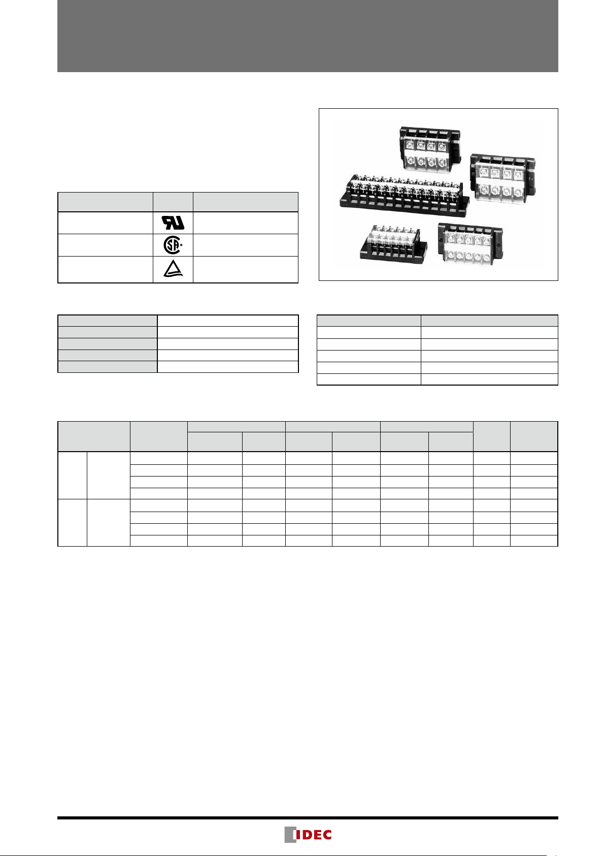
BTB/BTBH Series Surface Mount Terminal Blocks
Surface mount terminal blocks with 2 to 30 poles.
Touch-down terminals reduce wiring time.
• Self-lifting (BTB series) and touch down terminal (BTBH)
available.
• Flame-resistant plastic (UL94V-0).
• Terminal blocks can be easily combined and all poles can be
secured with a pair of connecting rods and nuts.
• Complies with JIS C 8201-7-1.
• UL recognized and CSA certified.
Applicable Standards Mark
UL1059
Certification Organization/
File No.
UL recognized
File No. E78117
CSA 22.2 No. 158
EN60947-1
EN60947-7-1
General Specifications
Dielectric Strength 2500V AC, 1 minute
Insulation Resistance 100 MΩ minimum
Operating Temperature –25 to +55°C (no freezing)
Storage Temperature –25 to +70°C (no freezing)
Operating Humidity 45 to 85% RH (no condensation)
CSA (File No. LR64803)
TÜV Rheinland
License No. R9551515
Material
Parts Name Material
Housing Modified PPE
Bus Bar Brass (nickel-plated)
Terminal Screw Steel (zinc chrome-plated)
Connecting Rod/Nut Steel (zinc chrome-plated)
Dust Cover Polycarbonate
Ratings and Terminal Screw Tightening Torque
Part Part No.
BTB15C
BTB Self-lifting
Touch-
BTBH
down
∗ The rated applicable wire size is 1.25 mm2, but 2 mm2 wire can also be used.
The wire size in ( ) does not comply with JIS standards.
The rated current differs according to operating conditions. See “Selecting Terminal Blocks by Current According to JIS Standards” on page4.
Specify the number of poles in place of .
BTB15LC
BTB30C
BTB50C
BTBH15C
BTBH15LC
BTBH30C
BTBH50C
300V/10A 22-14 500V/22A 2 (18-14) 630V/16A
300V/15A 22-12 500V/22A 2 (18-14) 630V/21A 2 M3.5 1.0 to 1.3
300V/30A 18-10 500V/38A 5.5 (14-10) 630V/40A 5.5 M4 1.4 to 2.0
600V/50A 16-6 500V/67A 14 (10 -6) 1000V/70A 14 M5 2.6 to 3.7
300V/10A 22-14 500V/22A 2 (18-14) 630V/16A
300V/15A 22-14 500V/22A 2 (18-14) 630V/21A 2 M3.5 1.0 to 1.3
300V/30A 18-10 500V/38A 5.5 (14-10) 630V/40A 5.5 M4 1.4 to 2.0
600V/50A 16-6 500V/67A 14 (10-6) 630V/70A 14 M5 2.6 to 3.7
UL/CSA EN JIS
Voltage/
Current
Wire Size
(AWG)
Voltage/
Current
Wire Size
(AWG)
Voltage/
Current
Wire Size
(mm
1.25 (2) ∗
1.25 (2) ∗
Terminal
Screw
2
)
M3 0.6 to 1.0
M3 0.6 to 1.0
Tightening
Torque
37
Page 2
BTB/BTBH Series Surface Mount Terminal Blocks
6.6 max.
ø3.2 min.
3.3 min.
BTB15C/BTBH15C
Style
BTB15C
(Self-lifting terminal)
Note: Dust covers and marking strips are supplied with the terminal block.
No. of
Poles
2 BTB15C2 1
3 BTB15C3 1
4 BTB15C4 1
5 BTB15C5 1
6 BTB15C6 1
7 BTB15C7 1
8 BTB15C8 1
9 BTB15C9 1
10 BTB15C10 1
11 BTB15C11 1
12 BTB15C12 1
13 BTB15C13 1
14 BTB15C14 1
15 BTB15C15 1
16 BTB15C16 1
17 BTB15C17 1
18 BTB15C18 1
19 BTB15C19 1
20 BTB15C20 1
21 BTB15C21 1
22 BTB15C22 1
23 BTB15C23 1
24 BTB15C24 1
25 BTB15C25 1
26 BTB15C26 1
27 BTB15C27 1
28 BTB15C28 1
29 BTB15C29 1
30 BTB15C30 1
Part No.
Package
Quantity
Style
BTBH15C
(Touch-down
terminal)
No. of
Poles
2 BTBH15C2 1
3 BTBH15C3 1
4 BTBH15C4 1
5 BTBH15C5 1
6 BTBH15C6 1
7 BTBH15C7 1
8 BTBH15C8 1
9 BTBH15C9 1
10 BTBH15C10 1
11 BTBH15C11 1
12 BTBH15C12 1
13 BTBH15C13 1
14 BTBH15C14 1
15 BTBH15C15 1
16 BTBH15C16 1
17 BTBH15C17 1
18 BTBH15C18 1
19 BTBH15C19 1
20 BTBH15C20 1
21 BTBH15C21 1
22 BTBH15C22 1
23 BTBH15C23 1
24 BTBH15C24 1
25 BTBH15C25 1
26 BTBH15C26 1
27 BTBH15C27 1
28 BTBH15C28 1
29 BTBH15C29 1
30 BTBH15C30 1
Part No.
Package
Quantity
Specifications
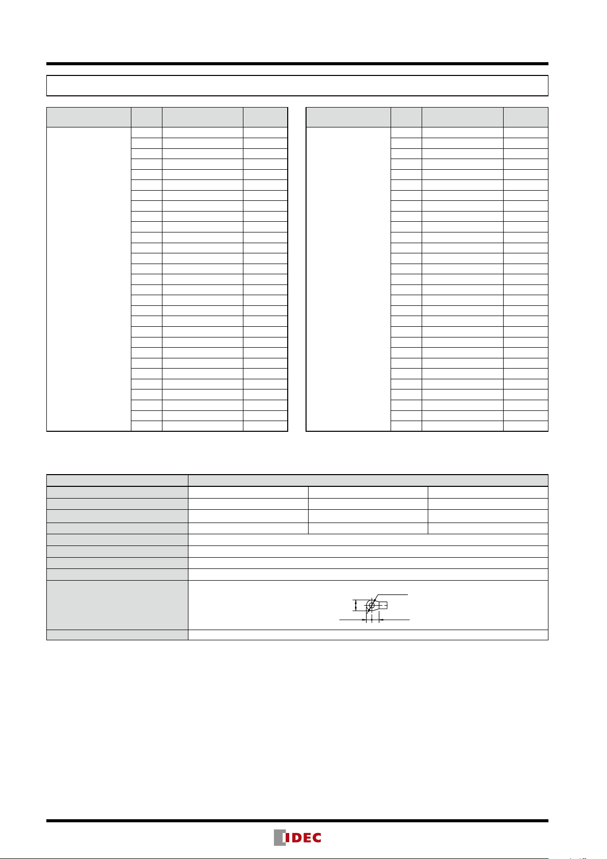
BTB15C/BTBH15C
Standards UL/CSA EN JIS
Insulation Voltage 300V 500V 630V
Wire Size 22-14 AWG 2 mm
Rated Current 10A 22A 16A
Terminal screw M3
Crimping Terminal 1.25-3 (2-3)
Max. No. of Crimping Terminals 2
Tightening Torque 0.6 to 1.0 N · m
Crimping Terminal Dimensions (mm)
Accessory: Jumper BNJ36, BNJ36B, BNJ36F, BNJ36FB (see page 43)
2
∗ The rated applicable wire size is 1.25 mm
The wire size in ( ) does not comply with JIS standards.
, but 2 mm2 wires can also be connected.
2
(18-14 AWG)
5 max.
1.25 mm
2
(2 mm2) ∗
38
Page 3
BTB/BTBH Series Surface Mount Terminal Blocks
8.5 max.
ø3.6 min.
BTB15LC/BTBH15LC
Style
BTB15LC
(Self-lifting terminal)
Note: Dust covers and marking strips are supplied with the terminal block.
No. of
Poles
2 BTB15LC2 1
3 BTB15LC3 1
4 BTB15LC4 1
5 BTB15LC5 1
6 BTB15LC6 1
7 BTB15LC7 1
8 BTB15LC8 1
9 BTB15LC9 1
10 BTB15LC10 1
11 BTB15LC11 1
12 BTB15LC12 1
13 BTB15LC13 1
14 BTB15LC14 1
15 BTB15LC15 1
16 BTB15LC16 1
17 BTB15LC17 1
18 BTB15LC18 1
19 BTB15LC19 1
20 BTB15LC20 1
21 BTB15LC21 1
22 BTB15LC22 1
23 BTB15LC23 1
24 BTB15LC24 1
25 BTB15LC25 1
26 BTB15LC26 1
27 BTB15LC27 1
28 BTB15LC28 1
29 BTB15LC29 1
30 BTB15LC30 1
Part No.
Package
Quantity
Style
BTBH15LC
(Touch-down
terminal)
No. of
Poles
2 BTBH15LC2 1
3 BTBH15LC3 1
4 BTBH15LC4 1
5 BTBH15LC5 1
6 BTBH15LC6 1
7 BTBH15LC7 1
8 BTBH15LC8 1
9 BTBH15LC9 1
10 BTBH15LC10 1
11 BTBH15LC11 1
12 BTBH15LC12 1
13 BTBH15LC13 1
14 BTBH15LC14 1
15 BTBH15LC15 1
16 BTBH15LC16 1
17 BTBH15LC17 1
18 BTBH15LC18 1
19 BTBH15LC19 1
20 BTBH15LC20 1
21 BTBH15LC21 1
22 BTBH15LC22 1
23 BTBH15LC23 1
24 BTBH15LC24 1
25 BTBH15LC25 1
26 BTBH15LC26 1
27 BTBH15LC27 1
28 BTBH15LC28 1
29 BTBH15LC29 1
30 BTBH15LC30 1
Part No.
Package
Quantity
Specifications
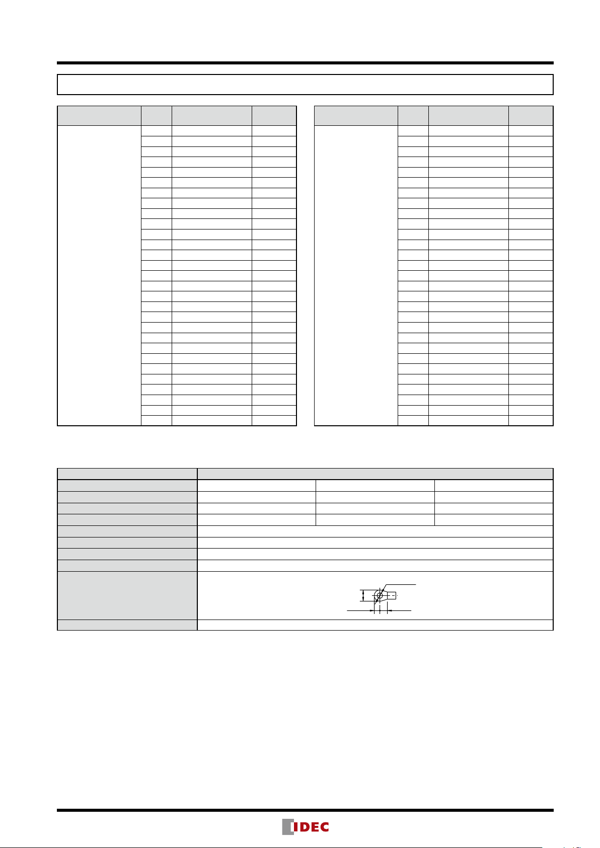
BTB15LC/BTBH15LC
Standards UL/CSA EN JIS
Insulation Voltage 300V 500V 630V
Wire Size 22-14 AWG 2 mm
Rated Current 15A 22A 21A
Terminal screw M3.5
Crimping Terminal 2-3.5
Max. No. of Crimping Terminals 2
Tightening Torque 1.0 to 1.3 N · m
Crimping Terminal Dimensions (mm)
Accessory: Jumper BNJ46, BNJ46B, BNJ46F, BNJ46FB (see page 43)
2
(18-14 AWG) 2 mm2
5 max.
4 min.
39
Page 4

BTB/BTBH Series Surface Mount Terminal Blocks
9.5 max.
ø4.2 min.
4.5 min.
BTB30C/BTBH30C
Style
BTB30C
(Self-lifting terminal)
Note: Dust covers and marking strips are supplied with the terminal block.
No. of
Poles
2 BTB30C2 1
3 BTB30C3 1
4 BTB30C4 1
5 BTB30C5 1
6 BTB30C6 1
7 BTB30C7 1
8 BTB30C8 1
9 BTB30C9 1
10 BTB30C10 1
11 BTB30C11 1
12 BTB30C12 1
13 BTB30C13 1
14 BTB30C14 1
15 BTB30C15 1
16 BTB30C16 1
17 BTB30C17 1
18 BTB30C18 1
19 BTB30C19 1
20 BTB30C20 1
21 BTB30C21 1
22 BTB30C22 1
23 BTB30C23 1
24 BTB30C24 1
25 BTB30C25 1
26 BTB30C26 1
27 BTB30C27 1
28 BTB30C28 1
29 BTB30C29 1
30 BTB30C30 1
Part No.
Package
Quantity
Style
BTBH30C
(Touch-down
terminal)
No. of
Poles
2 BTBH30C2 1
3 BTBH30C3 1
4 BTBH30C4 1
5 BTBH30C5 1
6 BTBH30C6 1
7 BTBH30C7 1
8 BTBH30C8 1
9 BTBH30C9 1
10 BTBH30C10 1
11 BTBH30C11 1
12 BTBH30C12 1
13 BTBH30C13 1
14 BTBH30C14 1
15 BTBH30C15 1
16 BTBH30C16 1
17 BTBH30C17 1
18 BTBH30C18 1
19 BTBH30C19 1
20 BTBH30C20 1
21 BTBH30C21 1
22 BTBH30C22 1
23 BTBH30C23 1
24 BTBH30C24 1
25 BTBH30C25 1
26 BTBH30C26 1
27 BTBH30C27 1
28 BTBH30C28 1
29 BTBH30C29 1
30 BTBH30C30 1
Part No.
Package
Quantity
Specifications
BTB30C/BTBH30C
Standards UL/CSA EN JIS
Insulation Voltage 300V 500V 630V
Wire Size 18-10 AWG 5.5 mm
Rated Current 30A 38A 40A
Terminal screw M4
Crimping Terminal 1.25-4 to 5.5-4
Max. No. of Crimping Terminals 2
Tightening Torque 1.4 to 2.0 N · m
Crimping Terminal Dimensions (mm)
Accessory: Jumper BNJ56, BNJ56B, BNJ56F, BNJ56FB (see page 43)
2
(14-10 AWG) 5.5 mm
6 max.
2
40
Page 5

BTB50C/BTBH50C
4.5 min.
12.8 max.
ø5.2 min.
BTB/BTBH Series Surface Mount Terminal Blocks
Style
BTB50C
(Self-lifting terminal)
Note: Dust cover and marking strips are supplied with the terminal block.
No. of
Poles
2 BTB50C2 1
3 BTB50C3 1
4 BTB50C4 1
5 BTB50C5 1
6 BTB50C6 1
7 BTB50C7 1
8 BTB50C8 1
9 BTB50C9 1
10 BTB50C10 1
11 BTB50C11 1
12 BTB50C12 1
13 BTB50C13 1
14 BTB50C14 1
15 BTB50C15 1
16 BTB50C16 1
17 BTB50C17 1
18 BTB50C18 1
19 BTB50C19 1
20 BTB50C20 1
Part No.
Package
Quantity
Style
BTBH50C
(Touch-down
terminal)
No. of
Poles
2 BTBH50C2 1
3 BTBH50C3 1
4 BTBH50C4 1
5 BTBH50C5 1
6 BTBH50C6 1
7 BTBH50C7 1
8 BTBH50C8 1
9 BTBH50C9 1
10 BTBH50C10 1
11 BTBH50C11 1
12 BTBH50C12 1
13 BTBH50C13 1
14 BTBH50C14 1
15 BTBH50C15 1
16 BTBH50C16 1
17 BTBH50C17 1
18 BTBH50C18 1
19 BTBH50C19 1
20 BTBH50C20 1
Part No.
Package
Quantity
Specifications
BTB50C/BTBH50C BTB50C BTBH50C
Standards UL/CSA EN JIS
Insulation Voltage 600V 500V 1000V 630V
Wire Size 16-6 AWG 14 mm
Rated Current 50A 67A 70A
Terminal screw M5
Crimping Terminal 1.25-5 to 14-5
Max. No. of Crimping Terminals 2
Tightening Torque 2.6 to 3.7 N · m
2
(10-6 AWG) 14 mm
2
Crimping Terminal Dimensions (mm)
6.5 max.
Accessory: Jumper BNJ62, BNJ62B (page 43)
41
Page 6

BTB/BTBH Series Surface Mount Terminal Blocks
M3
Recommended Tightening
M3.5
Recommended Tightening
M4
ightening
Recommended Tightening
Dimensions
• L (Length of the terminal block) and P (mounting hole centers) are nominal dimensions for each terminal block.
Because the terminal blocks are combined together with bolts, there may be differences in the dimensions depending on
the number of poles combined.
BTB15C/BTBH15C (8.5-mm Terminal Centers)
16A
12.5
6.7
M4 Hole
8.5
P
L
Dust Cover
Dimensions L and P (mm)
No. of
2 3 4 5 6 7 8 9 10 11 12 13 14 15 16
Poles
L 42 50.5 59 67.5 76 84.5 93
P 33 41.5 50 58.5 67 75.5 84 92.5 101
No. of
17 18 19 20 21 22 23 24 25 26 27 28 29 30 —
Poles
L
169.5
178
186.5
195
203.5
P
160.5
169
177.5
Weight (per pole) BTB15: Approx. 9g
BTBH15: Approx. 10g
186
194.5
212
203
Torque: 1.0 N·m
34
M3 Terminal Screw
14.5
28 max.
9.5
10 1.5
110
220.5
229
220
237.5
228.5
211.5
118.5
109.5
246
237
127
118
254.5
245.5
135.5
126.5
263
254
144
135
271.5
262.5
152.5
143.5
280 —
271 —
BTB15LC/BTBH15LC (
12.5
8.5
10.5
Dust Cover
Dimensions L and P (mm)
No. of
2 3 4 5 6 7 8 9 10 11 12 13 14 15 16
Poles
L 46 56.5 67 77.5 88 98.5 109
161
P 37 47.5 58 68.5 79 89.5 100
152
No. of
17 18 19 20 21 22 23 24 25 26 27 28 29 30 —
Poles
L
203.5
214
224.5
P
194.5
Weight (per pole) BTB15L: Approx. 12g
235
205
215.5
226
BTBH15L: Approx. 13g
P
L
245.5
236.5
10.5-mm Terminal Centers
M4 Hole
256
247
Torque: 1.0 N·m
34
M3.5 Terminal Screw
14.5
28 max.
9.5
119.5
130
110.5
121
266.5
277
268
287.5
278.5
257.5
140.5
131.5
298
289
151
142
308.5
299.5
161.5
152.5
319
310
21A
172
163
329.5
320.5
182.5
173.5
340 —
331 —
)
193
184
BTB30C/BTBH30C (12-mm Terminal Centers)
40A
12.5
9.6
12
Dust Cover
M4 Hole
P
L
Dimensions L and P (mm)
No. of
2 3 4 5 6 7 8 9 10 11 12 13 14 15 16
Poles
L 49 61 73 85 97 109 121 133 145 157 169 181 193 205 217
P 40 52 64 76 88 100 112 124 136 148 160 172 184 19 6 208
No. of
17 18 19 20 21 22 23 24 25 26 27 28 29 30 —
Poles
L 229 241 253 265 277 289 301 313 325 337 349 361 373 385 —
P 220 232 244 256 268 280 292 304 316 328 340 352 364 376 —
Weight (per pole) BTB30: Approx. 20g
BTBH30: Approx. 22g
Recommended T
Torque: 1.0 N·m
38
M4 Terminal Screw
16.4
31 max.
9.5
BTB50C/BTBH50C (15.5-mm Terminal Centers)
244
233
259.5
248.5
M5
275
264
13.5
13
15.5
Dust Cover
M5 Hole
P
L
Torque: 1.0 N·m
48
M5 Terminal Screw
19.3
38 max.
14
Dimensions L and P (mm)
No. of
2 3 4 5 6 7 8 9 10 11 12 13 14 15 16
Poles
L 58 73.5 89
P 47 62.5 78 93.5 109
No. of
17 18 19 20
Poles
L
290.5
P
279.5
Weight (per pole) BTB50: Approx. 35g
104.5
306
321.5
337
295
310.5
326
BTBH50: Approx. 40g
120
135.5
124.5
151
140
166.5
155.5
182
171
197.5
186.5
213
202
70A
228.5
217.5
42
Page 7

BTB/BTBH Series Surface Mount Terminal Blocks
Insulation
42.5 (6-pole)
1.4 min.
Insulation
R1.85
42.5 (6-pole)
1.4 min.
Insulation
2.8
5.5
11
10.5
52.5 (6-pole)
8.2
ø4.2
0.8
1.4
Insulation
2.8
5.511
10.5
4.5
8.2
R2.1
4.2
52.5 (6-pole)
1.4
0.8
Insulation
6 9.5
12
1.7
60 (6-pole)
ø4.2
9.3
0.8
1.4
Insulation
6 9.55.8
12
1.7
60 (6-pole)
R2.1
4.2
9.3
1.4
0.8
holes)
Accessories
The dust cover and marking strip (fiber) are supplied with the product.
Jumpers for 6 Poles (Material: Brass, Plating: Nickel, Insulation: PVC)
Terminal
Center
Shape Insulation Part No. Ordering No. Dimensions (mm)
Rated
Current
Package
Quantity
Applicable
Terminal
Block
8.5 mm
10.5 mm
12 mm
Ring
Fork
Ring
Fork
Ring
Fork
Without BNJ36 BNJ36PN10
With BNJ36B BNJ36BPN10
Without BNJ36F BNJ36FPN10
With BNJ36FB BNJ36FBPN10
Without BNJ46 BNJ46PN10
With BNJ46B BNJ46BPN10
Without BNJ46F BNJ46FPN10
With BNJ46FB BNJ46FBPN10
Without BNJ56 BNJ56PN10
With BNJ56B BNJ56BPN10
Without BNJ56F BNJ56FPN10
With BNJ56FB BNJ56FBPN10
ø3.7
8.5
6.4
9
4.5
8.5
6.4
3.7
9 4.5
4.5
0.8
2
20A 10
0.8
2
20A 10
30A 10
BTB15
BTBH15
BTB15L
BTBH15L
BTB30
BTBH30
Notes: Jumpers for more than 6 poles are not available.
Jumper for 2 poles
Part No. Ordering No.
BNJ62 BNJ62PN10
Terminal
Centers
Insulation Dimensions
Ring Terminal
Without
(
14.5 mm
BNJ62B BNJ62BPN10 With
• Material: nickel-coated brass
• Sheath: PVC
Note 1: Ensure that the total current to the jumper does not exceed the maximum current.
Note 2: Ensure that the current does not exceed the rated current of the terminal block to be used.
Current
(Note 1, 2)
80A
Applicable
Terminal Block
BTB50
BTBH50
Package
Quantity
10
Marking Strip (Supplied with the terminal block. Order as spare parts when necessary)
Applicable Terminal Block
BTB/BTBH
(all models)
Part No. Ordering No. Material Size Package Quantity
BNM9 BNM9PN10
Fiber strip
(matte surface)
1000 mm × 9.5 mm × 0.5 mm 10
Dust Cover (Supplied with the terminal block. Order as spare parts when necessary)
Applicable Terminal Block Ordering No. Material Length
BTB15C/BTBH15C
BTB15LC/BTBH15LC
BTB-CV15L1 Polycarbonate 500 mm 1
BTB30C/BTBH30C BTB-CV30L1 Polycarbonate 500 mm 1
BTB50C/BTBH50C BTB-CV50L1 Polycarbonate 500 mm 1
Package Quantity
43
Page 8

BTB/BTBH Series Surface Mount Terminal Blocks
Wire
Insulation
Terminal Metal Part
Washer Width
Safety Precautions
Notes on Wiring
Crimping Terminals
• When using crimping terminals, be sure to use insulated terminals to prevent electric
shocks.
Without Crimping Terminals
• Insert the wire until the insulation comes into contact with the terminal metal part.
• Strip the insulation so that the wire is longer than the width of the wire clamp.
• When connecting two wires, use wires of the same length.
• To prevent damage, ensure to use plain washers when installing.
44
 Loading...