

Page 1
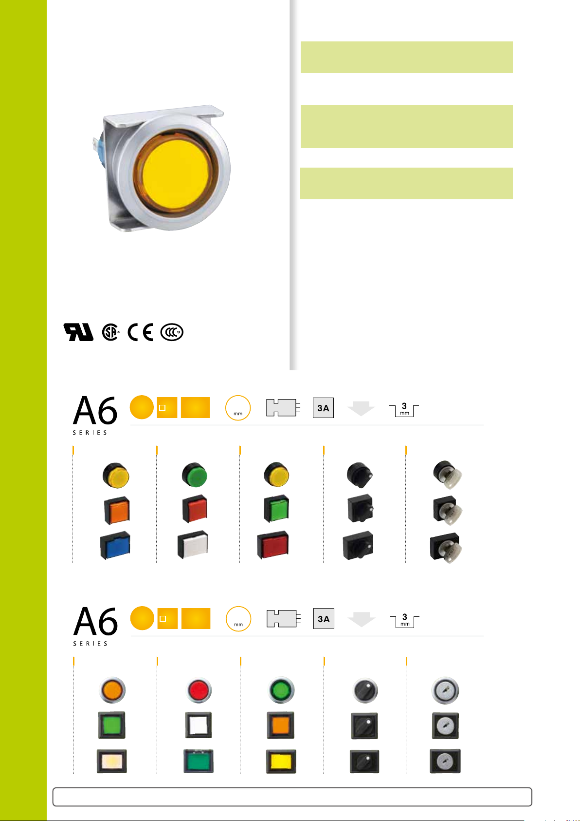
ø16 Switches & Pilot Lights
[ Bezel size ][ From panel front ][ Shape ][ Contact rating ][ Action ]
[ Operating stroke ]
Suitable for a wide variety of
office and factory aplications.
A6 Series
Light duty in short 22 mm body length.
Flush bezel accessories can be used
to change A6 series to Flush Silhouette
switches.
• See website for details on approvals and standards.
Features IDEC’s original mechanism for snap-action switching.
The LED lamp contains a current-limiting
resistor and a diode for protection
against reverse connection.
Degree of protection: IP40 and IP65
(IEC 60529)
Standard Bezel
ø18 18
Illuminated Pushbuttons Pilot Lights Selector Switches Key Selector SwitchesPushbuttons
Flush Bezel
ø24
Illuminated Pushbuttons Pilot Lights Selector Switches Key Selector SwitchesPushbuttons
Flush bezel accessories provide a sleek updated look. Enables downsizing of equipment.
18×24
[ Bezel size ][ From panel front ][ Shape ][ Contact rating ][ Action ][ Operating stroke ]
24
18×24
9
2
Unibody
Unibody
Light
Light
Unibody
B-147
Page 2

ø16 A6 Series Miniature Switches & Pilot Lights
(+) (–)
Resistor
Protection Diode
Light duty in short 22mm body length.
Specications and Ratings
Contact Ratings (Contact Block)
Rated Insulation Voltage 250V
Rated Thermal Current 3A
Operating Voltage (AC/DC) 12V 24V 110V 220V
AC 50/60 Hz
DC
Contact Material Gold plated silver
• Minimum applicable load: 5V AC/DC, 1 mA
(applicable range may vary with operating conditions and load types)
Resistive Load — — 1.0A 0.5A
Inductive Load — — 0.7A 0.5A
Resistive Load 1.0A 1.0A 0.2A —
Inductive Load 0.7A 0.7A 0.1A —
Weight (example)
AL6M-M24: 8g
AL6M-M221: 46g
AL6M-P4: 6g
Weight (approx.)
AL6M-P21: 45g
AB6M-M2: 7g
AS6M-2Y2: 9g
AS6M-2KT2A: 21g
Specifications
Operating Temperature –25 to +55°C (no freezing)
Storage Temperature –30 to +80°C (no freezing)
Operating Humidity 45 to 85% RH (no condensation)
Contact Resistance 50 mΩ maximum (initial value)
Insulation Resistance 100 MΩ minimum (500V DC megger)
Between live and dead metal parts: 2,000V AC, 1 minute
Switch Unit
Strength
Dielectric
Illumination Unit
Vibration Resistance
Shock Resistance
Mechanical Durability
(minimum operations)
Electrical Durability
(minimum operations)
Degree of Protection IP40, IP65 (IEC 60529)
Terminal Style Solder terminal
Between terminals of different poles: 2,000V AC, 1 minute
Between terminals of the same pole: 1,000V AC, 1 minute
Between contact and lamp terminals: 1,500V AC, 1 minute
Between live part and ground: 2,000V AC, 1 minute
Operating extremes: 5 to 55 Hz, amplitude 0.75 mm
Damage limits: 500 m/s
Operating extremes: 200 m/s2 (20G)
Momentary: 1,000,000 operations
Maintained: 100,000 operations
Pushlock Turn Reset
Selector Switch: 250,000 operations
Key Selector Switch: 250,000 operations
Other than Maintained
Maintained: 50,000 operations
(Switching frequency 1200 operations/h)
2
(50G)
: 100,000 operations
: 100,000 operations
Switches & Pilot Lights
APEM
Switches &
Pilot Lights
Control Boxes
Emergency
Stop Switches
Enabling
Switches
Safety Products
Explosion Proof
Terminal Blocks
Relays & Sockets
Circuit
Protectors
Power Supplies
LED Illumination
Controllers
Operator
Interfaces
Sensors
AUTO-ID
Flush Silhouette
ø16
ø22
ø30
Miniature
Pilot Lights
LED Lamp Ratings (LATD)
Part No.
Lamp Base Exclusive for A series control units
Voltage Range 5V DC ±5% 12V AC/DC ±10% 24V AC/DC ±10%
Rated Voltage 5V DC 12V AC/DC 24V AC/DC
Current Draw
Color Code
Lamp Base Color Same as illumination color (except JW - gray base)
Voltage Marking Die stamped on the base
Life (reference value) Approx. 50,000 hours (The luminance is reduced to 50% of the initial intensity when used on complete DC.)
Internal Circuit
• Specify a color code in place of ➁ in the Part No.
A (amber), G (green), JW (pure white), R (red), S (blue)
• Use a pure white (JW) LED lamp for yellow illumination.
LATD-5
➁
AC — 9 mA (A, G, R), 8 mA (JW, S) 9 mA (A, GC, R), 8 mA (JW, SC)
DC 8 mA (A, G, R), 7 mA (JW, S) 8 mA (A, G, R), 7 mA (JW, S) 8 mA (A, GC, R), 7 mA (JW, SC)
➁
A (amber), G (green), JW (pure white), R (red), S (blue)
Download catalogs and CAD from http://asia.idec.com/downloads
LATD-1
➁
LED Chip
Zener Diode
LATD-2
LB
➁
A6
B-148
Page 3
Switches & Pilot Lights
APEM
Switches &
Pilot Lights
Control Boxes
Emergency
Stop Switches
Enabling
Switches
Safety Products
Explosion Proof
Terminal Blocks
Relays & Sockets
Circuit
Protectors
Power Supplies
LED Illumination
Controllers
Operator
Interfaces
Sensors
AUTO-ID
Flush Silhouette
ø16
ø22
ø30
Miniature
Pilot Lights
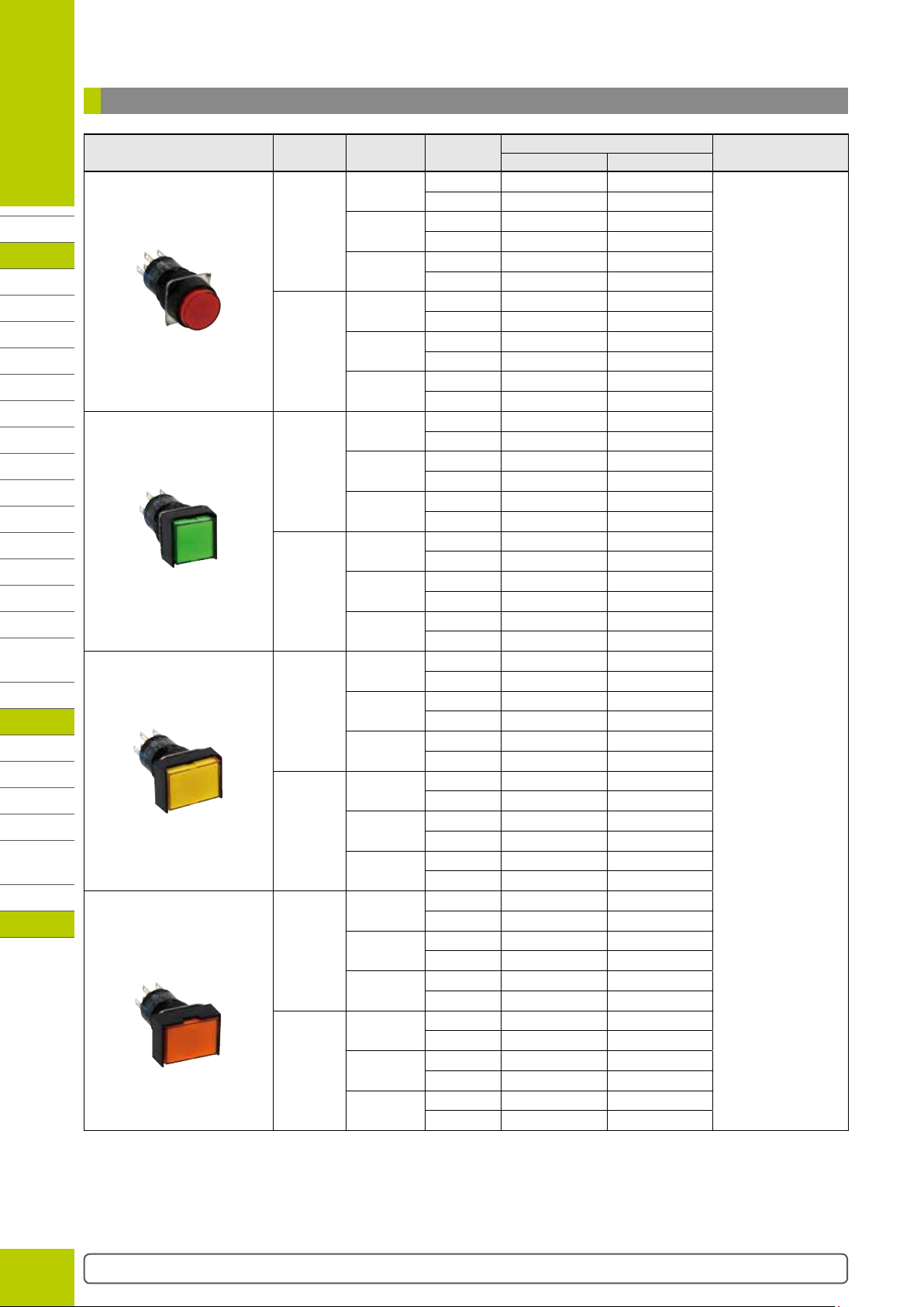
ø16 A6 Series Miniature Switches & Pilot Lights
Illuminated Pushbuttons
Package Quantity: 1
Shape Operation
Round
AL6M
Momentary
Maintained
Square
AL6Q
Momentary
Maintained
Rectangular
AL6H
Momentary
Maintained
LB
Rectangular
w/three-sided barrier
A6
AL6G
Momentary
Maintained
• See B-151 for dimensions.
• See B-166 for marking plate size and engraving area.
• A pure white (JW) LED lamp is used for yellow illumination.
• Part No. with “C” after the color code uses polycarbonate lens.
Operating
Voltage
5V DC
12V AC/DC
24V AC/DC
5V DC
12V AC/DC
24V AC/DC
5V DC
12V AC/DC
24V AC/DC
5V DC
12V AC/DC
24V AC/DC
5V DC
12V AC/DC
24V AC/DC
5V DC
12V AC/DC
24V AC/DC
5V DC
12V AC/DC
24V AC/DC
5V DC
12V AC/DC
24V AC/DC
Contact
SPDT AL6M-M11➁ AL6M-M11P➁
DPDT
SPDT
DPDT
SPDT
DPDT
SPDT
DPDT
SPDT
DPDT
SPDT
DPDT
SPDT
DPDT
SPDT
DPDT
SPDT
DPDT
SPDT
DPDT
SPDT
DPDT
SPDT
DPDT
SPDT
DPDT
SPDT
DPDT
SPDT
DPDT
SPDT
DPDT
SPDT
DPDT
SPDT
DPDT
SPDT
DPDT
SPDT
DPDT
SPDT
DPDT
SPDT
DPDT
SPDT
DPDT
SPDT
DPDT
AL6M-M21➁ AL6M-M21P➁
AL6M-M13➁ AL6M-M13P➁
AL6M-M23➁ AL6M-M23P➁
AL6M-M14➁C AL6M-M14P➁C
AL6M-M24➁C AL6M-M24P➁C
AL6M-A11➁ AL6M-A11P➁
AL6M-A21➁ AL6M-A21P➁
AL6M-A13➁ AL6M-A13P➁
AL6M-A23➁ AL6M-A23P➁
AL6M-A14➁C AL6M-A14P➁C
AL6M-A24➁C AL6M-A24P➁C
AL6Q-M11➁ AL6Q-M11P➁
AL6Q-M21➁ AL6Q-M21P➁
AL6Q-M13➁ AL6Q-M13P➁
AL6Q-M23➁ AL6Q-M23P➁
AL6Q-M14➁C AL6Q-M14P➁C
AL6Q-M24➁C AL6Q-M24P➁C
AL6Q-A11➁ AL6Q-A11P➁
AL6Q-A21➁ AL6Q-A21P➁
AL6Q-A13➁ AL6Q-A13P➁
AL6Q-A23➁ AL6Q-A23P➁
AL6Q-A14➁C AL6Q-A14P➁C
AL6Q-A24➁C AL6Q-A24P➁C
AL6H-M11➁ AL6H-M11P➁
AL6H-M21➁ AL6H-M21P➁
AL6H-M13➁ AL6H-M13P➁
AL6H-M23➁ AL6H-M23P➁
AL6H-M14➁C AL6H-M14P➁C
AL6H-M24➁C AL6H-M24P➁C
AL6H-A11➁ AL6H-A11P➁
AL6H-A21➁ AL6H-A21P➁
AL6H-A13➁ AL6H-A13P➁
AL6H-A23➁ AL6H-A23P➁
AL6H-A14➁C AL6H-A14P➁C
AL6H-A24➁C AL6H-A24P➁C
AL6G-M11➁ AL6G-M11P➁
AL6G-M21➁ AL6G-M21P➁
AL6G-M13➁ AL6G-M13P➁
AL6G-M23➁ AL6G-M23P➁
AL6G-M14➁ AL6G-M14P➁
AL6G-M24➁ AL6G-M24P➁
AL6G-A11➁ AL6G-A11P➁
AL6G-A21➁ AL6G-A21P➁
AL6G-A13➁ AL6G-A13P➁
AL6G-A23➁ AL6G-A23P➁
AL6G-A14➁ AL6G-A14P➁
AL6G-A24➁ AL6G-A24P➁
Part No.
IP40 IP65
➁ Illumination
Color Code
Specify a color code in
place of ➁ in the Part No.
A: amber
G: green
JW: pure white
R: red
S: blue
Y: yellow
B-149
Page 4

ø16 A6 Series Miniature Switches & Pilot Lights
Pilot Lights
Package Quantity: 1
Round
AL6M-P
Square
AL6Q-P
Rectangular
AL6H-P
Shape Operating Voltage
5V DC
12V AC/DC
24V AC/DC
5V DC
12V AC/DC
24V AC/DC
5V DC
12V AC/DC
Part No.
IP40 IP65
AL6M-P1➁ AL6M-P1P➁
AL6M-P3➁ AL6M-P3P➁
AL6M-P4➁C AL6M-P4P➁C
AL6Q-P1➁ AL6Q-P1P➁
AL6Q-P3➁ AL6Q-P3P➁
AL6Q-P4➁C AL6Q-P4P➁C
AL6H-P1➁ AL6H-P1P➁
AL6H-P3➁ AL6H-P3P➁
➁ Illumination
Color Code
Specify a color code in place of
➁ in the Part No.
A: amber
G: green
JW: pure white
R: red
S: blue
Y: yellow
Switches & Pilot Lights
APEM
Switches &
Pilot Lights
Control Boxes
Emergency
Stop Switches
Enabling
Switches
Safety Products
Explosion Proof
Terminal Blocks
Relays & Sockets
Circuit
Protectors
Power Supplies
LED Illumination
Controllers
Operator
Interfaces
Sensors
AUTO-ID
24V AC/DC
Rectangular w/three-sided barrier
AL6G-P
5V DC
12V AC/DC
24V AC/DC
• See B-151 for dimensions.
• See B-166 for marking plate size and engraving area.
• A pure white (JW) LED lamp is used for yellow illumination.
• Part No. with “C” after the color code uses polycarbonate lens.
AL6H-P4➁C AL6H-P4P➁C
AL6G-P1➁ AL6G-P1P➁
AL6G-P3➁ AL6G-P3P➁
AL6G-P4➁ AL6G-P4P➁
Flush Silhouette
ø16
ø22
ø30
Miniature
Pilot Lights
LB
A6
Download catalogs and CAD from http://asia.idec.com/downloads
B-150
Page 5

Switches & Pilot Lights
2.6
1.0
1.2
Panel Thickness 0.5 to 6
Pilot Light Illuminated Pushbutton
(TOP)
Terminal (–)
(TOP)
+0.2
18 min.
+0.2
18 min.
ø16 A6 Series Miniature Switches & Pilot Lights
APEM
Switches &
Pilot Lights
Control Boxes
Emergency
Stop Switches
Enabling
Switches
Safety Products
Explosion Proof
Terminal Blocks
Relays & Sockets
Circuit
Protectors
Power Supplies
LED Illumination
Controllers
Operator
Interfaces
Sensors
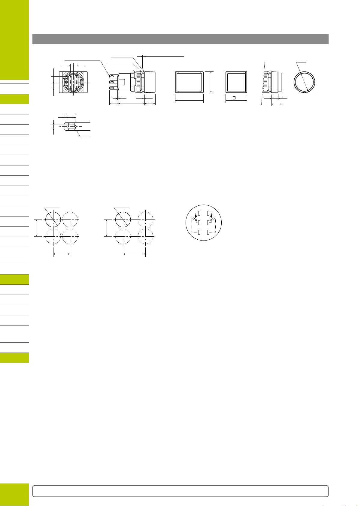
Dimensions (Illuminated Pushbuttons & Pilot Lights)
Terminal Width 2.8×0.5t
2.5 3
55
66
Rubber Gasket
Anti-rotation Ring
Locking Ring
1 0.6
8229
Terminal Arrangement (bottom view)
Illuminated Pushbutton Pilot Light
NC1
NC2
NO1
NO2
C1
Lamp
Terminal (+)
C2
Lamp
Terminal (–)
With contact: NC1, NO1, C1 terminal only
Lamp
Terminal (+)
Lamp
All dimensions in mm.
Rectangular
Rectangular w/3-way barrier Round
(
)
TOP
24
2-R0.6
Square
(
)
TOP
18
18
5.7
9
*Solder/tab terminal
Ø18
(
TOP
)
AUTO-ID
Flush Silhouette
ø16
ø22
ø30
Miniature
Pilot Lights
Mounting Hole Layout
Round/Square Rectangular
ø16.2
0
18 min.
LB
A6
Rectangular w/3-way barrier
ø16.2
0
24 min.
Note: Determine mounting centers to
ensure easy operation.
B-151
Page 6
ø16 A6 Series Miniature Switches & Pilot Lights
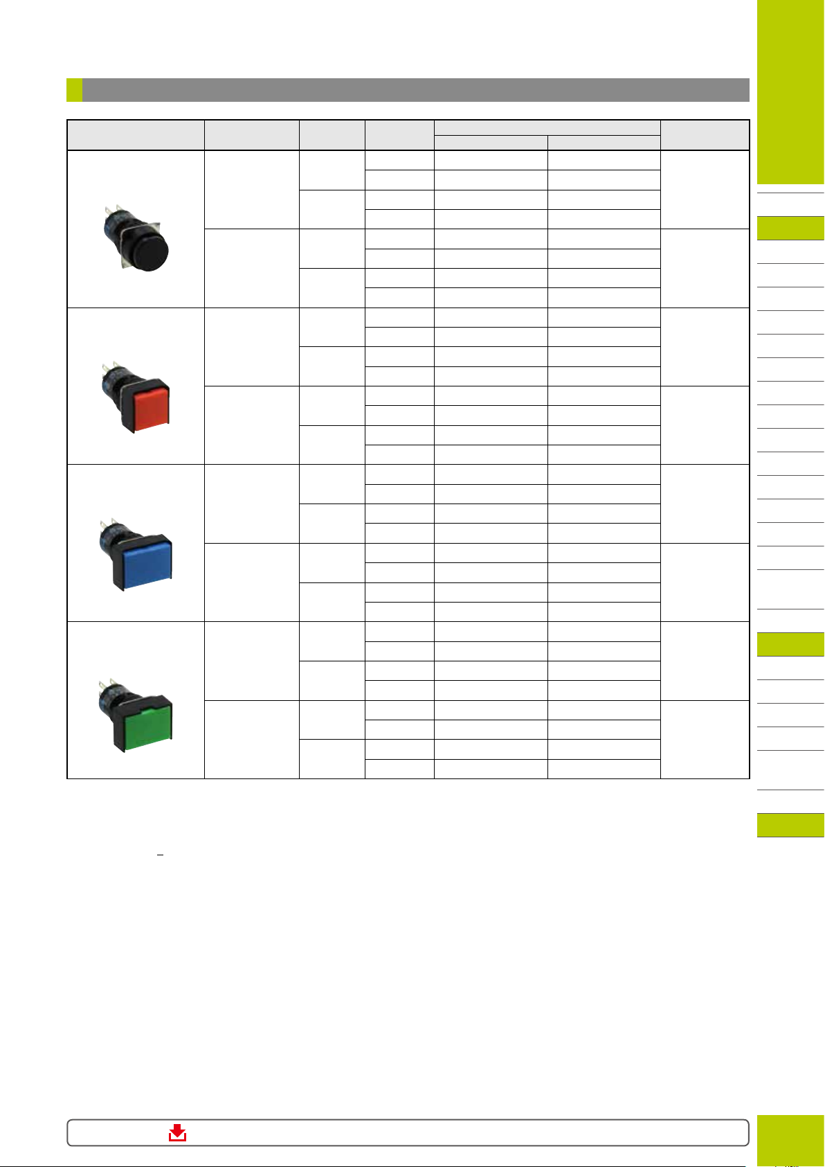
Pushbuttons
Package Quantity: 1
Shape Button Style Operation Contact
Round
AB6M
Square
AB6Q
Rectangular
AB6H
Rectangular
w/three-sided barrier
AB6G
Button
Lens
Button
Lens
Button
Lens
Button
Lens
Momentary
Maintained
Momentary
Maintained
Momentary
Maintained
Momentary
Maintained
Momentary
Maintained
Momentary
Maintained
Momentary
Maintained
Momentary
Maintained
SPDT
DPDT
SPDT
DPDT
SPDT
DPDT
SPDT
DPDT
SPDT
DPDT
SPDT
DPDT
SPDT
DPDT
SPDT
DPDT
SPDT
DPDT
SPDT
DPDT
SPDT
DPDT
SPDT
DPDT
SPDT
DPDT
SPDT
DPDT
SPDT
DPDT
SPDT
DPDT
IP40 IP65
AB6M-M1➀C AB6M-M1P➀C
AB6M-M2➀C AB6M-M2P➀C
AB6M-A1➀C AB6M-A1P➀C
AB6M-A2➀C AB6M-A2P➀C
AB6M-M1L➁ AB6M-M1PL➁
AB6M-M2L➁ AB6M-M2PL➁
AB6M-A1L➁ AB6M-A1PL➁
AB6M-A2L➁ AB6M-A2PL➁
AB6Q-M1➀C AB6Q-M1P➀C
AB6Q-M2➀C AB6Q-M2P➀C
AB6Q-A1➀C AB6Q-A1P➀C
AB6Q-A2➀C AB6Q-A2P➀C
AB6Q-M1L➁ AB6Q-M1PL➁
AB6Q-M2L➁ AB6Q-M2PL➁
AB6Q-A1L➁ AB6Q-A1PL➁
AB6Q-A2L➁ AB6Q-A2PL➁
AB6H-M1➀C AB6H-M1P➀C
AB6H-M2➀C AB6H-M2P➀C
AB6H-A1➀C AB6H-A1P➀C
AB6H-A2➀C AB6H-A2P➀C
AB6H-M1L➁ AB6H-M1PL➁
AB6H-M2L➁ AB6H-M2PL➁
AB6H-A1L➁ AB6H-A1PL➁
AB6H-A2L➁ AB6H-A2PL➁
AB6G-M1➀ AB6G-M1P➀
AB6G-M2➀ AB6G-M2P➀
AB6G-A1➀ AB6G-A1P➀
AB6G-A2➀ AB6G-A2P➀
AB6G-M1L➁ AB6G-M1PL➁
AB6G-M2L➁ AB6G-M2PL➁
AB6G-A1L➁ AB6G-A1PL➁
AB6G-A2L➁ AB6G-A2PL➁
• Specify a color code in place of ➀ or ➁ in the Part No.
• See B-151 for dimensions.
• See B-166 for marking plate size and engraving area.
• Black is available for lens style buttons. Black lens consists of a clear lens and a black marking plate. Specify “B” in place of ➁ in the Part No.
Example:AB6H-M2LB
• Part No. with “C” after the color code uses polycarbonate lens.
Part No.
Color Code ➀➁
B black
G: green
R: red
S: blue
W: white
Y: yellow
A: amber
G: green
R: red
S: blue
W: white
Y: yellow
B black
G: green
R: red
S: blue
W: white
Y: yellow
A: amber
G: green
R: red
S: blue
W: white
Y: yellow
B black
G: green
R: red
S: blue
W: white
Y: yellow
A: amber
G: green
R: red
S: blue
W: white
Y: yellow
B black
G: green
R: red
S: blue
W: white
Y: yellow
A: amber
G: green
R: red
S: blue
W: white
Y: yellow
Switches & Pilot Lights
APEM
Switches &
Pilot Lights
Control Boxes
Emergency
Stop Switches
Enabling
Switches
Safety Products
Explosion Proof
Terminal Blocks
Relays & Sockets
Circuit
Protectors
Power Supplies
LED Illumination
Controllers
Operator
Interfaces
Sensors
AUTO-ID
Flush Silhouette
ø16
ø22
ø30
Miniature
Pilot Lights
LB
A6
Download catalogs and CAD from http://asia.idec.com/downloads
B-152
Page 7
Switches & Pilot Lights
Pushbutton
+0.2
18 min.
ø16.2
+0.2
18 min.
(TOP)
2.6
2-R0.6
1.0
1.2
ø16 A6 Series Miniature Switches & Pilot Lights
APEM
Switches &
Pilot Lights
Control Boxes
Emergency
Stop Switches
Enabling
Switches
Safety Products
Explosion Proof
Terminal Blocks
Relays & Sockets
Circuit
Protectors
Power Supplies
LED Illumination
Controllers
Operator
Interfaces
Sensors
AUTO-ID
Dimensions (Pushbuttons)
Terminal Width 2.8×0.5t
2.5 3
55
* Solder/Tab Terminal
• See B-164 for lens and button maintenance parts.
Rubber Gasket
Anti-rotation Ring
Locking Ring
1
8229
Mounting Hole Layout
Round/Square Rectangular
ø16.2
0
18 min.
w/3-way barrier
0
24 min.
Panel Thickness 0.5 to 6
0.6
Rectangular
Rectangular w/3-way barrier
)
(
)
TOP
18
TOP
1824
Terminal Arrangement (bottom view)
Pushbutton
NC1
NC2
NO1
NO2
C1
C2
Note: SPDT has only NC1, NO1, and C1 terminals.
All dimensions in mm.
ø18
RoundSquare
(
)(
TOP
5.7
9
Flush Silhouette
ø16
ø22
ø30
Miniature
Pilot Lights
Note: Determine mounting centers to ensure easy operation.
LB
A6
B-153
Page 8

Selector Switches
L
R
NOCNC—NOCNC
L
R
Left
NO
C
Right
Contact
C
NC
NO
C
C
NC
Left
Contact
Right
C
R
L
NO
C
C
NC
Left
Contact
Right
Contact
Left
Contact
NO
C
Right
Contact
C
NC
NO
C
C
NC
Left
Contact
Right
L
C
R
LCR
C
LR
R
L
(C)
R
L
R
L
(C)
L
R
ø16 A6 Series Miniature Switches & Pilot Lights
Switches & Pilot Lights
Operator position can be changed by IDEC’s original bezel rotating
How to change the operator position
and locking system. The bezel can be locked at every 45° and bezel
rotation is prevented while mounting on a panel.
Example: 3-position
(C)
Normal Operator Position
Package Quantity: 1
Shape Position Contact
Round
AS6M-Y
Maintained
90°
2-position
Spring return from right to left
SPDT AS6M-2Y1C AS6M-2Y1PC
DPDT AS6M-2Y2C AS6M-2Y2PC
SPDT AS6M-21Y1C AS6M-21Y1PC
DPDT AS6M-21Y2C AS6M-21Y2PC
Maintained DPDT AS6M-3Y2C AS6M-3Y2PC
Spring return from right to center DPDT AS6M-31Y2C AS6M-31Y2PC
45°
Spring return from left to center DPDT AS6M-32Y2C AS6M-32Y2PC
3-position
Spring return two-way DPDT AS6M-33Y2C AS6M-33Y2PC
Square
AS6Q-Y
Maintained
90°
2-position
Spring return from right to left
SPDT AS6Q-2Y1C AS6Q-2Y1PC
DPDT AS6Q-2Y2C AS6Q-2Y2PC
SPDT AS6Q-21Y1C AS6Q-21Y1PC
DPDT AS6Q-21Y2C AS6Q-21Y2PC
Maintained DPDT AS6Q-3Y2C AS6Q-3Y2PC
Spring return from right to center DPDT AS6Q-31Y2C AS6Q-31Y2PC
45°
Spring return from left to center DPDT AS6Q-32Y2C AS6Q-32Y2PC
3-position
Spring return two-way DPDT AS6Q-33Y2C AS6Q-33Y2PC
Rectangular
AS6H-Y
Maintained
90°
2-position
Spring return from right to left
SPDT AS6H-2Y1C AS6H-2Y1PC
DPDT AS6H-2Y2C AS6H-2Y2PC
SPDT AS6H-21Y1C AS6H-21Y1PC
DPDT AS6H-21Y2C AS6H-21Y2PC
Maintained DPDT AS6H-3Y2C AS6H-3Y2PC
Spring return from right to center DPDT AS6H-31Y2C AS6H-31Y2PC
45°
Spring return from left to center DPDT AS6H-32Y2C AS6H-32Y2PC
3-position
Spring return two-way DPDT AS6H-33Y2C AS6H-33Y2PC
• Bezel: black • Knob: black
(C)
Pull out the bezel to release the lock. Rotate the bezel, and push it in at 45°
intervals to lock the bezel.
Part No.
IP40 IP65
Package Quantity: 1
Contact Operation
Position
Operation
Maintained
90° 2-position
Spring return
from right
Maintained
Spring return
from right
45° 3-position
Spring return
from left
Two-way
return
Left Center Right
SPDT
DPDT
Contact
NC
NO
—
DPDT
NC
NC NO
NO
NC NO
NC NO
Contact
Contact
APEM
Switches &
Pilot Lights
Control Boxes
Emergency
Stop Switches
Enabling
Switches
Safety Products
Explosion Proof
Terminal Blocks
Relays & Sockets
Circuit
Protectors
Power Supplies
LED Illumination
Controllers
Operator
Interfaces
Sensors
AUTO-ID
Flush Silhouette
ø16
ø22
ø30
Miniature
Pilot Lights
LB
A6
Download catalogs and CAD from http://asia.idec.com/downloads
B-154
Page 9

Switches & Pilot Lights
(TOP)
+0.2
18 min.
+0.2
18 min.
55
Panel Thickness 0.5 to 6
ø16 A6 Series Miniature Switches & Pilot Lights
APEM
Switches &
Pilot Lights
Control Boxes
Emergency
Stop Switches
Enabling
Switches
Safety Products
Explosion Proof
Terminal Blocks
Relays & Sockets
Circuit
Protectors
Power Supplies
LED Illumination
Controllers
Operator
Interfaces
Sensors
Dimensions (Selector Switches)
All dimensions in mm.
Dimensions All dimensions in mm.
Terminal Width 2.8×0.5t
2.5 3
Terminal Arrangement (bottom view)
(Selector Switch)
NC1
NC2
NO1
NO2
C1
C2
SPDT has NC1, NO1, and C1 only.
Rubber Gasket
Anti-rotation Ring
Locking Ring
1
8
Rectangular
(
)
TOP
18
8
22
15.5
24
Square
(
TOP
18
)
Round
(
TOP
)
ø18
Mounting Hole Layout
Round/Square Rectangular
ø16.2
0
18 min.
Note: Determine mounting centers to ensure easy operation.
ø16.2
0
24 min.
AUTO-ID
Flush Silhouette
ø16
ø22
ø30
Miniature
Pilot Lights
LB
A6
B-155
Page 10

ø16 A6 Series Miniature Switches & Pilot Lights
LR
R
L
R
C
C
LR
C
C
C
C
C
C
C
LR
RL
NOCNC—NOCNC
Left
Contact
NOCNC
Right
Contact
NOCNC
NOCNC NOCNC
Left
Contact
Right
Contact
RL
C
RL
C
L
C
R
C
R
L
NOCNC NOCNC
Left
Contact
Right
Contact
Left
Contact
NOCNC
Right
Contact
NOCNC
NOCNC NOCNC
Left
Contact
Right
Contact
Key Selector Switches
Package Quantity: 1
Part No.
Round
AS6M
Shape Position Operation
Maintained
90°
2-position
Spring return from right B
Maintained
45°
3-position
Spring return from right
Spring return from left
Spring return two-way
Key Retained
at ●
A
B
C
A
B
C
D
E
G
H
B
D
G
C
D
H
D
L
L
LCR
L
L
C
L
C
L
L
L
L
C
L
L
C
L
L
L
Contact
IP40 IP65
SPDT AS6M-2KT1AC AS6M-2KT1PAC
DPDT AS6M-2KT2AC AS6M-2KT2PAC
SPDT AS6M-2KT1BC AS6M-2KT1PBC
DPDT AS6M-2KT2BC AS6M-2KT2PBC
R
SPDT AS6M-2KT1CC AS6M-2KT1PCC
DPDT AS6M-2KT2CC AS6M-2KT2PCC
SPDT AS6M-21KT1BC AS6M-21KT1PBC
DPDT AS6M-21KT2BC AS6M-21KT2PBC
DPDT AS6M-3KT2AC AS6M-3KT2PAC
R
DPDT AS6M-3KT2BC AS6M-3KT2PBC
R
DPDT AS6M-3KT2CC AS6M-3KT2PCC
R
DPDT AS6M-3KT2DC AS6M-3KT2PDC
DPDT AS6M-3KT2EC AS6M-3KT2PEC
R
DPDT AS6M-3KT2GC AS6M-3KT2PGC
R
DPDT AS6M-3KT2HC AS6M-3KT2PHC
R
DPDT AS6M-31KT2BC AS6M-31KT2PBC
R
DPDT AS6M-31KT2DC AS6M-31KT2PDC
R
DPDT AS6M-31KT2GC AS6M-31KT2PGC
R
DPDT AS6M-32KT2CC AS6M-32KT2PCC
R
DPDT AS6M-32KT2DC AS6M-32KT2PDC
R
DPDT AS6M-32KT2HC AS6M-32KT2PHC
R
DPDT AS6M-33KT2DC AS6M-33KT2PDC
Switches & Pilot Lights
APEM
Switches &
Pilot Lights
Control Boxes
Emergency
Stop Switches
Enabling
Switches
Safety Products
Explosion Proof
Terminal Blocks
Relays & Sockets
Circuit
Protectors
Power Supplies
LED Illumination
Controllers
Operator
Interfaces
Sensors
AUTO-ID
Flush Silhouette
ø16
ø22
ø30
Miniature
Pilot Lights
• Key is retained at ● positions and removable at positions.
• Two keys are supplied.
• The front of key cylinder is made of metal.
• Only one type of key is available
Contact Operation
Operator Position & Contact Operation (Top View)
Positions Contact
90° 2-position
Maintained
Spring return from right
45° 3-position
Maintained
Spring return
from right
Spring return
from left
Download catalogs and CAD from http://asia.idec.com/downloads
Spring return
two-way
SPDT
DPDT
DPDT
LB
A6
Left Center Right
—
B-156
Page 11

Switches & Pilot Lights
LR
R
C
C
LR
C
C
C
C
C
C
C
C
LR
RL
NOCNC—NOCNC
Left
Contact
NOCNC
Right
Contact
NOCNC
NOCNC NOCNC
Left
Contact
Right
Contact
RL
C
RL
C
L
C
R
C
R
L
NOCNC NOCNC
Left
Contact
Right
Contact
Left
Contact
NOCNC
Right
Contact
NOCNC
NOCNC NOCNC
Left
Contact
Right
Contact
APEM
Switches &
Pilot Lights
Control Boxes
Emergency
Stop Switches
Enabling
Switches
Safety Products
Explosion Proof
Terminal Blocks
Relays & Sockets
Circuit
Protectors
Power Supplies
LED Illumination
Controllers
Operator
Interfaces
Sensors
AUTO-ID
Flush Silhouette
ø16
ø22
ø16 A6 Series Miniature Switches & Pilot Lights
Key Selector Switches
Package Quantity: 1
Part No.
Square
AS6Q
Shape Position Operation
Maintained
90°
2-position
Spring return from right B
Maintained
45°
3-position
Spring return from right
Spring return from left
Key Retained
at ●
A
B
C
A
B
C
D
E
G
H
B
D
G
C
D
L
L
L
LCR
L
L
L
L
L
L
L
L
L
L
Contact
IP40 IP65
SPDT AS6Q-2KT1AC AS6Q-2KT1PAC
DPDT AS6Q-2KT2AC AS6Q-2KT2PAC
SPDT AS6Q-2KT1BC AS6Q-2KT1PBC
DPDT AS6Q-2KT2BC AS6Q-2KT2PBC
R
SPDT AS6Q-2KT1CC AS6Q-2KT1PCC
DPDT AS6Q-2KT2CC AS6Q-2KT2PCC
R
SPDT AS6Q-21KT1BC AS6Q-21KT1PBC
DPDT AS6Q-21KT2BC AS6Q-21KT2PBC
DPDT AS6Q-3KT2AC AS6Q-3KT2PAC
R
DPDT AS6Q-3KT2BC AS6Q-3KT2PBC
C
R
DPDT AS6Q-3KT2CC AS6Q-3KT2PCC
R
DPDT AS6Q-3KT2DC AS6Q-3KT2PDC
DPDT AS6Q-3KT2EC AS6Q-3KT2PEC
R
DPDT AS6Q-3KT2GC AS6Q-3KT2PGC
R
DPDT AS6Q-3KT2HC AS6Q-3KT2PHC
R
DPDT AS6Q-31KT2BC AS6Q-31KT2PBC
R
DPDT AS6Q-31KT2DC AS6Q-31KT2PDC
C
R
DPDT AS6Q-31KT2GC AS6Q-31KT2PGC
R
DPDT AS6Q-32KT2CC AS6Q-32KT2PCC
C
R
DPDT AS6Q-32KT2DC AS6Q-32KT2PDC
ø30
Miniature
Pilot Lights
• Key is retained at ● positions and removable at positions.
• Two keys are supplied.
• The front of key cylinder is made of metal.
LB
• Only one type of key is available.
A6
Contact Operation
Positions Contact
90° 2-position
45° 3-position
Maintained
Maintained
Spring return
from right
H
Spring return two-way D
Operator Position & Contact Operation (Top View)
Spring return from right
Spring return
from left
Spring return
two-way
R
L
L
DPDT AS6Q-32KT2HC AS6Q-32KT2PHC
R
DPDT AS6Q-33KT2DC AS6Q-33KT2PDC
Left Center Right
SPDT
DPDT
—
DPDT
B-157
Page 12

ø16 A6 Series Miniature Switches & Pilot Lights
LR
L
R
L
R
L
R
LCR
L
C
R
C
R
L
C
R
L
LR
C
L
C
R
C
L
R
C
L
R
C
R
L
L
C
R
C
R
L
C
R
L
C
L
R
C
R
L
LR
RL
NOCNC—NOCNC
Left
Contact
NOCNC
Right
Contact
NOCNC
NOCNC NOCNC
Left
Contact
Right
Contact
RL
C
RL
C
L
C
R
C
R
L
NOCNC NOCNC
Left
Contact
Right
Contact
Left
Contact
NOCNC
Right
Contact
NOCNC
NOCNC NOCNC
Left
Contact
Right
Contact
Key Selector Switches
Package Quantity: 1
Part No.
Rectangular
AS6H
Shape Position Operation
Maintained
90°
2-position
Spring return from right B
Key Retained
at ●
A
B
C
A
B
Contact
SPDT
IP40 IP65
AS6H-2KT1AC AS6H-2KT1PAC
DPDT AS6H-2KT2AC AS6H-2KT2PAC
SPDT AS6H-2KT1BC AS6H-2KT1PBC
DPDT AS6H-2KT2BC AS6H-2KT2PBC
SPDT AS6H-2KT1CC AS6H-2KT1PCC
DPDT AS6H-2KT2CC AS6H-2KT2PCC
SPDT AS6H-21KT1BC AS6H-21KT1PBC
DPDT AS6H-21KT2BC AS6H-21KT2PBC
DPDT AS6H-3KT2AC AS6H-3KT2PAC
DPDT AS6H-3KT2BC AS6H-3KT2PBC
Switches & Pilot Lights
APEM
Switches &
Pilot Lights
Control Boxes
Emergency
Stop Switches
Enabling
Switches
Safety Products
Explosion Proof
Maintained
45°
3-position
Spring return from right
Spring return from left
Spring return two-way
• Key is retained at ● positions and removable at positions.
• Two keys are supplied.
• The front of key cylinder is made of metal.
• Only one type of key is available.
C
DPDT AS6H-3KT2CC AS6H-3KT2PCC
Terminal Blocks
Relays & Sockets
D
E
G
DPDT AS6H-3KT2DC AS6H-3KT2PDC
DPDT AS6H-3KT2EC AS6H-3KT2PEC
DPDT AS6H-3KT2GC AS6H-3KT2PGC
Circuit
Protectors
Power Supplies
LED Illumination
Controllers
H
B
DPDT AS6H-3KT2HC AS6H-3KT2PHC
DPDT AS6H-31KT2BC AS6H-31KT2PBC
Operator
Interfaces
Sensors
AUTO-ID
D
G
DPDT AS6H-31KT2DC AS6H-31KT2PDC
DPDT AS6H-31KT2GC AS6H-31KT2PGC
Flush Silhouette
C
D
H
DPDT AS6H-32KT2CC AS6H-32KT2PCC
DPDT AS6H-32KT2DC AS6H-32KT2PDC
DPDT AS6H-32KT2HC AS6H-32KT2PHC
ø16
ø22
ø30
Miniature
D
DPDT
AS6H-33KT2DC AS6H-33KT2PDC
Pilot Lights
LB
A6
Contact Operation
90° 2-position
45° 3-position
Maintained
Operator Position & Contact Operation (Top View)
Positions Contact
Left Center Right
SPDT
Maintained
Spring return from right
DPDT
—
DPDT
Spring return
from right
Spring return
from left
Spring return
two-way
Download catalogs and CAD from http://asia.idec.com/downloads
B-158
Page 13

Switches & Pilot Lights
2.6
2-R0.6
1.0
1.2
Rubber Gasket
55
Panel Thickness 0.5 to 6
TOP
3 2.5
Left Contact
Right Contact
(TOP)
+0.2
18 min.
+0.2
18 min.
7
17
8.1
Key No.
t =1.8
ø16 A6 Series Miniature Switches & Pilot Lights
APEM
Switches &
Pilot Lights
Control Boxes
Emergency
Stop Switches
Enabling
Switches
Safety Products
Explosion Proof
Terminal Blocks
Relays & Sockets
Circuit
Protectors
Power Supplies
LED Illumination
Controllers
Operator
Interfaces
Sensors
AUTO-ID
Dimensions
Terminal Width 2.8×0.5t
2.5 3
NC
NO
C
Anti-rotation Ring
Locking Ring
1
82226
Mounting Hole Layout
Round/Square Rectangular
ø16.2
0
18 min.
Note: Determine mounting centers to ensure easy operation.
ø16.2
0
24 min.
All dimensions in mm.
Round Square
(
)
TOP
9
ø18
(
TOP
)
18
Rectangular
(
)
TOP
24
18
Terminal Arrangement (bottom view)
(Key Selector Switch)
NC1
NC2
NO1
NO2
C1
C2
SPDT has NC1, NO1, and C1 only.
Flush Silhouette
ø16
ø22
ø30
Miniature
Pilot Lights
Spare Key
18
ø3.0
∗
LB
A6
B-159
Page 14

ø16 A6 Series Miniature Switches & Pilot Lights
Spring Return
26
ø18
Mounting Hole
Mounting Hole
Gaske
2.512
6
Switches & Pilot Lights
Accessories
Locking Ring Wrench
Lamp Holder Tool
ø10
Lens Removal Tool
[Remains open}
For pushbuttons,
illuminated
pushbuttons
[Spring return]
For pushbuttons,
illuminated
pushbuttons
Switch Guard
Dust Cover
➀ ➁ ➂
Terminal Cover
Socket
Mounting Hole Plug
Shape Material Part No. Ordering No.
ø18
60
ø9
Metal
(nickel-plated
brass)
MT-001 MT-001 1
Rubber OR-77 OR-77 1 • Used to install and remove the LED lamps.
55
Stainless Steel MT-101 MT-101 1
60
For round/
square units
LB9Z-K2 LB9Z-K2 1
(110°, 180°)
For rectangular
units (remains
110°
180°
LB9Z-K3P LB9Z-K3P 1
110°, 180°)
Guard
For round/
square units
(180°)
(polyacetal)
Cover
(polyarylate)
See B-161 for
dimen sions.
AL-K6S AL-K6S 1
AL-K6SP AL-K6SP 1
AL-KH6S AL-KH6S 1
For rectangular
units (180°)
➀ For round
units
➁ For square
units
➂
For rectangular
units
Translucent cover:
elastomer
Black part:
polypropylene
AL-KH6SP
AL-D6 AL-D6 1
AL-DQ6 AL-DQ6 1
AL-DH6 AL-DH6 1
AL-KH6SP
Polyamide (white)
See B-162 for
AL-V6 AL-V6PN10 10
dimen sions.
➀
➁
➀ Solder
Terminal
➁ PC Board
Terminal
AL-C6 AL-C6 1
See B-162 for
dimen sions.
AL-C6V AL-C6V 1
Package
Quantity
1
All dimensions in mm.
Remarks
• Used to tighten the locking ring when
installing A6 control units into a panel.
• Used to install and remove lenses and
buttons.
• Degree of protection: IP40
• Used to protect pushbuttons from
inadvertent operation.
• Degree of protection: IP65
• Used to protect pushbuttons from
inadvertent operation.
• Degree of protection: IP40
• Used to protect pushbuttons from
inadvertent operation.
• Degree of protection: IP65 (when used
with IP65 control units)
• Used to protect pushbuttons from
inadvertent operation.
• Degree of protection: IP40
• Used to protect pushbuttons from
inadvertent operation.
• Degree of protection: IP65 (when used
with IP65 control units)
• Used to protect pushbuttons from
inadvertent operation.
• When mounting the control units with the
dust covers installed, refer to mounting
hole layout on B-162.
• Operating temperature: –10 to +55°C
• When wiring the terminals, insert the lead
wires into the terminal cover holes before
soldering.
• Terminal cover is not attached and must
be ordered separately.
• Plugs on the rear of the A series control
units.
• Degree of protection: IP65
APEM
Switches &
Pilot Lights
Control Boxes
Emergency
Stop Switches
Enabling
Switches
Safety Products
Explosion Proof
Terminal Blocks
Relays & Sockets
Circuit
Protectors
Power Supplies
LED Illumination
Controllers
Operator
Interfaces
Sensors
AUTO-ID
Flush Silhouette
ø16
ø22
ø30
Miniature
Pilot Lights
LB
A6
Mounting Hole Plug
Rubber
Nitryl rubber
(black)
AL-B6 AL-B6PN05 5
ø16.5
• Degree of protection: IP65
Plug: metal
• Tightening torque: 0.1 to 0.29 N·m.
(diecast)
Metal
Locking ring:
polyacetal
Gasket: nitrile
AL-BM6 AL-BM6 1
ø17.8
t
Locking Ring
Panel Thickness 0.5 to
Download catalogs and CAD from http://asia.idec.com/downloads
ø16.2
ø16.2
+0.2
0
+0.2
0
B-160
Page 15

Switches & Pilot Lights
Panel Thickness
Panel Thickness
Panel Thickness
Panel Thickness
Panel Thickness
Waterproof
Gasket for Switch
Guard
Panel Thickness
Waterproof
Gasket for Switch
Guard
ø16 A6 Series Miniature Switches & Pilot Lights
APEM
Switches &
Pilot Lights
Control Boxes
Emergency
Stop Switches
Enabling
Switches
Safety Products
Explosion Proof
Terminal Blocks
Relays & Sockets
Circuit
Protectors
Power Supplies
LED Illumination
Controllers
Operator
Interfaces
Sensors
AUTO-ID
Dimensions
Switch Guard
[Remains open]
For round/square units (Degree of protection: IP40)
LB9Z-K2
0.5 to 5.6
Rubber Gasket
[Spring return]
For round/square units (Degree of protection: IP40)
AL-K6S
0.5 to 5
Rubber Gasket
12.4
32.7
32.9
110°
180°
34
R22
33
All dimensions in mm.
For rectangular units (Degree of protection: IP65)
LB9Z-K3P
0.5 to 5.6
18
13
11
23.5
Rubber Gasket
12.4
32.7
110°
180°
32.9
24
13
11
23.5
For rectangular units (Degree of protection: IP40)
AL-KH6S
0.5 to 5
18
13
11
23.5
Rubber Gasket
34
R22
33
24
13
11
23.5
Flush Silhouette
ø16
ø22
ø30
Miniature
Pilot Lights
13.5
For round/square units (Degree of protection: IP65)
AL-K6SP
0.5 to 5
Rubber Gasket
LB
A6
34
R22
13.50.4
13.5
For rectangular units (Degree of protection: IP65)
AL-KH6SP
0.5 to 5
33
18
13
11
23.5
Rubber Gasket
34
R22
13.50.4
33
24
13
11
23.5
B-161
Page 16

ø16 A6 Series Miniature Switches & Pilot Lights
+0.3
(Bottom View)
17.3
ø24
0.3 13
for Dust Cover
0.3
13
24
for Dust Cover
0.3
13
30
for Dust Cover
ø16.2
+0.2
24 min.
+0.2
24 min.
Anti-rotation Ring
Locking Ring
Rubber Gasket
Terminal Width 2.8×0.5t
Round
(
TOP
)
Rectangular
(
TOP
)
Square
(
TOP
)
2.5 3
55
66 1 0.6 9
822
15.5
Panel Thickness 0.5 to 6
AL6Q-LK2-H➁
AB6Q-BK2-H➁
AL6Q-LK2-Q➁
AB6Q-BK2-Q➁
AL6Q-LK2-M➁
AB6Q-BK2-M➁
23.5
17.5
0.6 9
15.5
23.5
ø23.5
0.6
12.5
Switches & Pilot Lights
Dimensions
Socket
8-1.6 Holes
0
32.5
66
PC Board
Mounting Hole Layout
0
55
(
AL-C6V
Terminal 1.5×0.3t
33.5
16.2 3.8
)
33.5
16.2 7.5
2.4
Solder Terminal
(
)
AL-C6
TOP
2.5 3
66
55
PC Board Terminal
Terminal Cover
Note: When wiring the terminals, insert the lead wires
ø16.8
33.5
into the terminal cover holes before soldering.
Dust Cover Mounting Hole Centers
For Round Units
(AL-D6)
For Square Units
(AL-DQ6)
For Rectangular Units
(AL-DH6)
Round/Square Units Rectangular Units
All dimensions in mm.
Lamp
Terminal (+)
Terminal Arrangement
(Bottom View)
ø16.2
(
TOP
NC1 NC2
NO1 NO2
C1 C2
0
)
Lamp
Terminal (–)
APEM
Switches &
Pilot Lights
Control Boxes
Emergency
Stop Switches
Enabling
Switches
Safety Products
Explosion Proof
Terminal Blocks
Relays & Sockets
Circuit
Protectors
Power Supplies
LED Illumination
Controllers
Operator
Interfaces
Sensors
7.5
Waterproof Gasket
Large Lens and Large Button
7.5
Waterproof Gasket
24
7.5
Waterproof Gasket
24 min.
30 min.
AUTO-ID
Flush Silhouette
ø16
ø22
ø30
Miniature
Pilot Lights
LB
A6
Download catalogs and CAD from http://asia.idec.com/downloads
B-162
Page 17

Switches & Pilot Lights
1.5 (LAPP)
HE5B Enabling Switch
Head
Housing
Cable Gland
20
33
SUS304
3.0 mm
APEM
Switches &
Pilot Lights
Control Boxes
Emergency
Stop Switches
Enabling
Switches
Safety Products
Explosion Proof
Terminal Blocks
Relays & Sockets
Circuit
Protectors
Power Supplies
LED Illumination
Controllers
Operator
Interfaces
Sensors
AUTO-ID
ø16 A6 Series Miniature Switches & Pilot Lights
Grip Switch Housing
Grip Style Enabling Switch Housing
The following switches can be installed on the grip style enabling switch
housing to be used as hand-held switches.
• AB6M pushbuttons (IP65, except for AB6M-V)
• AS6M selector switches (IP65)
• AS6M key selector switches (IP65)
Note: Illuminated pushbuttons and pilot lights cannot be used. When using HE9Z-
GSH51, be sure to used IP65 switches.
Part No. Ordering No. Package Quantity
HE9Z-GSH51 HE9Z-GSH51 1
Specications
Applicable Standards IEC/EN 60529
Operating Temperature –25 to 60°C (no freezing)
Relative Humidity 45 to 85% RH (no condensation)
Storage Temperature –40 to 80°C (no freezing)
Pollution Degree 3
Shock Resistance Damage limits: 500 m/s
Vibration Resistance Damage limits: 5 to 55 Hz, amplitude 0.5 mm
Electric Shock Protection Class
Class II (when using HE5B-M2P*)
Applicable Cable Outside diameter ø4.5 to 10 mm
Conduit Port Size
Degree of Protection
M16 (cable gland is supplied with the grip style
enabling switch housing)
IP65 (with HE5B-M2P*)
NEMA type 4X indoor use only
(with HE5B-M2P*)
Weight (approx.) 65g (grip style enabling switch housing only)
• The above specications are for the grip style enabling switch housing only.
2
Notes:
• The HE9Z-GSH51 grip style enabling switch housing does not
include the HE5B enabling switch. The enabling switch must be
ordered separately.
• The HE5B enabling switch must be installed and wired to the
HE9Z-GSH51 grip style enabling switch housing by the user. For
infor mation on wiring, see the instruction sheet supplied with
the HE9Z-GSH51.
Flush Silhouette
ø16
ø22
ø30
Miniature
Pilot Lights
Dimensions
HE9Z-GSH51
HE9Z-GSH51 + HE5B Construction
LB
A6
Mounting Bracket
Part No: HE9Z-GH1
(ordered separately)
144
92
39
Cable Gland
Part No. SKINTOP BS-M16 =
38
Locking Ring
HE5B Enabling Switch (not supplied with the grip style enabling switch housing)
(78)
• Anti-rotation ring is not required when installing the HE5B enabling switch on the HE9Z-GSH51 grip style enabling
switch housing. Use the locking ring only.
50
2-ø5.3
(For M5 mounting screws)
Plastic Coating
B-163
81
86
Material:
Thickness:
All dimensions in mm.
Page 18

Maintenance Parts
ø16 A6 Series Miniature Switches & Pilot Lights
Switches & Pilot Lights
Lens
Button
Marking Plate
Large Lens Unit
Locking Ring
Shape Specication Part No. Ordering No.
Round
Square
Rectangular
Round
Square
Rectangular
Round
Square
Rectangular
Round (installed
on round units)
Square (installed
on square units)
Rectangular
(installed on
square units)
Polyarylate
Polyarylate
Acrylic
Translucent
color lens
Opaque
button
Translucent
color lens
Opaque
button
Translucent
color lens
Opaque
button
White AL6M-W AL6M-WPN05
Black AL6M-B AL6M-BPN05
White AL6Q-W AL6Q-WPN05
Black AL6Q-B AL6Q-BPN05
White AL6H-W AL6H-WPN05
Black AL6H-B AL6H-BPN05
AL6M-L➁ AL6M-L➁PN05
AL6Q-L➁ AL6Q-L➁PN05
AL6H-L➁ AL6H-L➁PN05
AB6M-B➀ AB6M-B➀PN05
AB6Q-B➀ AB6Q-B➀PN05
AB6H-B➀ AB6H-B➀PN05
AL6M-LK2-M➁ AL6M-LK2-M➁
AB6M-BK2-M➁ AB6M-BK2-M➁
AL6Q-LK2-Q➁ AL6Q-LK2-Q➁
AB6Q-BK2-Q➁ AB6Q-BK2-Q➁
AL6Q-LK2-H➁ AL6Q-LK2-H➁
AB6Q-BK2-H➁ AB6Q-BK2-H➁
Package
Quantity
5
1
Remarks
Specify a color code in place of ➁ in the
Part No.
A (amber), C (clear), G (green)
R (red), S (blue), Y (yellow)
• Use a C (clear) lens for JW (pure white)
illumination.
Specify a color code in place of ➀ in the
Part No.
B (black), G (green), R (red)
S (blue), W (white), Y (yellow)
• Specify a color code in place of ➁ in
the Part No.
• Degree of protection: IP65
➁ Color Code
Translucent Color Lens Opaque Button
A (amber)
G (green)
R (red)
S (blue)
W (white)
Y (yellow)
Note: Use a white (W) translucent color lens for
pure white (JW) illumination.
B (black)
G (green)
R (red)
S (blue)
W (white)
Y (yellow)
• See B-162 for dimensions.
APEM
Switches &
Pilot Lights
Control Boxes
Emergency
Stop Switches
Enabling
Switches
Safety Products
Explosion Proof
Terminal Blocks
Relays & Sockets
Circuit
Protectors
Power Supplies
LED Illumination
Controllers
Operator
Interfaces
Sensors
AUTO-ID
Flush Silhouette
ø16
ø22
ø30
Anti-rotation Ring
Spare key
Spare Key
Reversible
Non-reversible
Gasket
Key selector
(disc tumbler key)
Key selector
(wave key)
Polyacetal HA9Z-LN HA9Z-LNPN10
Stainless Steel LB9Z-LP1 LB9Z-LP1PN10
Brass with
nickel plating
Diecast zinc alloy
(nickel-plated)
AS6-SK-132 AS6-SK-132PN02 2 • Thickness 1.8 mm
LA9Z-SK- LA9Z-SK-PN02
Rubber AP6M-WM AP6M-WMPN10 10
• Black
10
• Specify a key number in place of in
the Part No.
2
0H: Standard key (reversible)
1H to 2H: Reversible key
3H to 6H: Non-reversible key
Miniature
Pilot Lights
LB
A6
Download catalogs and CAD from http://asia.idec.com/downloads
B-164
Page 19

Switches & Pilot Lights
13.3
BAA1000
M3.5
T
APEM
Switches &
Pilot Lights
Control Boxes
Emergency
Stop Switches
Enabling
Switches
Safety Products
Explosion Proof
Terminal Blocks
Relays & Sockets
Circuit
Protectors
Power Supplies
LED Illumination
Controllers
Operator
Interfaces
Sensors
ø16 A6 Series Miniature Switches & Pilot Lights
LED Lamps
Dimensions
Operating
Volt age
5V DC ±5% —
8 mA (A, R, W)
6V DC ±5%
12
4
12V AC/DC ±10%
Voltage
Electrode
24V AC/DC ±10%
7 mA (G)
6 mA (JW, S)
9 mA (A, G, R, W)
8 mA (JW, S)
9 mA (A, G, R, W)
8 mA (JW, S)
• Use a pure white (JW) LED lamp for yellow illumination
Current Draw
AC DC
8 mA (A, G, R, W)
7 mA (JW, S)
6 mA (A, R, W)
5 mA (G)
4 mA (JW, S)
8 mA (A, G, R, W)
7 mA (JW, S)
8 mA (A, G, R, W)
7 mA (JW, S)
Transformer
Transformer Primary Voltage Secondary Voltage Part No. (Ordering No.)
For 24V
• Terminal cover is supplied as standard.
• Connect only one LATD to a transformer.
100/110V AC ±10% TWR512
200/220V AC ±10% TWR522
400/440V AC ±10% TWR542
Part No. Ordering No.
LATD-5➁
LATD-5➁
LATD-5➁PN10
LATD-6➁
LATD-6➁
LATD-6➁PN10
LATD-1➁
LATD-1➁
LATD-1➁PN10
LATD-2➁
LATD-2➁
LATD-2➁PN10
➁ Illumination
Color Code
Specify a color code
in place of ➁ in the
Ordering No.
A: amber
G: green
JW: pure white
R: red
S: blue
W: white
Package
Quantity
1
10
1
10
1
10
1
10
Applicable LED
LATD-2➁
Base
Exclusive for
A6 series
Package Quantity: 1
AUTO-ID
Flush Silhouette
ø16
ø22
ø30
Miniature
Pilot Lights
Specifications
Operating Voltage
Current Draw 2.4VA
Rated Insulation Voltage 600V
Insulation Resistance 100 MΩ minimum (500V DC megger)
Operating Temperature –30 to +60°C (no freezing)
Storage Temperature –40 to +80°C (no freezing)
Operating Humidity 35 to 85% RH (no condensation)
Vibration Resistance
Shock Resistance
Dielectric Strength 2,500V AC, 1 minute
Terminal Screw M3.5
Applicable Wire 2 mm
LB
Weight (approx.) 87g
A6
100/110V AC, 200/220V AC,
400/440V AC (50/60Hz)
Damage limits: 30Hz, amplitude 1.5 mm
Operating extremes: 5 to 55Hz, amplitude 0.5 mm
Damage limits: 1,000 m/s
Operating extremes: 100 m/s
2
maximum, 2 wires maximum
2
2
Dimensions All dimensions in mm.
Terminal Screw
2
Secondary Side Primary Side
2-ø3.3
Mounting Hole
erminal Cover
5
JAPAN
PRI.
22
SEC.
1
3 4
40
48
52
30
41
40
45.5
Accessories When ordering, specify the Ordering No.
Shape Material Part No. Ordering No. Package Quantity
DIN 35 mm Rail
Weight: 200g approx
DIN 35 mm Rail
Weight: 320g approx
End Clip
Aluminum
Length: 1000 mm
Steel
Length: 1000 mm
BAA1000 BAA1000PN10 10
BAP1000 BAP1000PN10 10
Metal (zinc-plated steel)
Applicable rail: BAA1000, BAP1000
BNL6 BNL6PN10 10
Weight: 15g approx
• See H-071 for DIN rail products.
B-165
Page 20

Safety Precautions
ø
12.0
0.8
0.8
12.0
0.8
13.6ø
13.6
ø10
For removing lampsFor installing lamps
ø16 A6 Series Miniature Switches & Pilot Lights
Switches & Pilot Lights
• Turn off the power to A series control units before starting installation,
removal, wiring, maintenance, and inspection of the control units.
Failure to turn power off may cause electrical shocks or re hazard.
• To avoid a burn on your hand, use the lamp holder tool when
replacing lamps.
Operating Instructions
Replacement of Lens and Marking Plate
Removal
Remove the lens assembly (color lens, marking plate, lens holder, and
spring) by holding the color lens recesses with the Lens Removal Tool
(MT-101) and pulling it out. Remove the marking plate by disengaging
the latches between the color lens and lens holder.
The marking plate must be engraved on the front side as shown at
right.
When using a color film, insert it between the color lens and marking
plate.
Engraving
Surface
Fitting Grooves
Grooves
Color Lens Marking Plate Lens Holder
Installation
Place the marking plate on the lens holder in the correct direction, and
press the color lens onto the lens holder to engage the latches.
Put the spring on the lens holder and insert the lens holder into the
housing in the correct direction.
Marking
For A series illuminated pushbuttons, legends and symbols can be
engraved on the built-in marking plates, or printed film can be inserted
under the lens for labelling purposes.
Marking Plate & Engraving Area
Round Square Rectangular
Engraving
Area
12.0
Engraving Area
• Engraving must be made on the engraving area within 0.5mm deep.
• The marking plate is made of white acrylic resin.
Built-in Marking Plate and
Engraving
Area
12.0
Engraving
Area
18.0
• For wiring, use wires of a proper size to meet the voltage and
current requirements. Failure to tighten terminal screws may cause
overheating and create a re hazard.
All dimensions in mm.
Replacing the LED Lamp
Removal
Use the lamp holder tool (OR-77) to remove lamps. Do not use pliers.
Installation
Use the lamp holder tool (OR-77) to install lamps. Note the correct side
of the tool for removal or installation.
OR-77
55
ø9
Panel Mounting
When mounting the control units into a panel, use the optional locking
ring wrench (MT-001) to tighten the locking ring. Do not use pliers.
Tightening torque must not exceed 0.88 N·m. Excessive tightening will
damage the locking ring.
Wiring
Solder the terminal at 350°C within 3 seconds using a 60W soldering
iron. Sn-Ag-Cu is recommended when using lead-free solder. When
soldering, do not touch the control unit with the soldering iron. Also
ensure that no tensile force is applied to the terminal. Do not bend the
terminal or apply excessive force to the terminal. Use a non-corrosive
rosin flux.
Installing the Socket
Install the socket on the control unit with the TOP markings on the
control unit and the socket placed in the same direction.
Switch Guard
IP65 (IEC 60529) switch guards must be used with IP65 (IEC 60529)
control units only. Even if IP65 type switch guards are installed,
enclosed type (IP40) control units are not made waterproof.
Switch Guard
Control Unit
Item
IP65 (IEC 60529) IP40 (IEC 60529)
IP65 IP65 IP40
IP40 IP40 IP40
APEM
Switches &
Pilot Lights
Control Boxes
Emergency
Stop Switches
Enabling
Switches
Safety Products
Explosion Proof
Terminal Blocks
Relays & Sockets
Circuit
Protectors
Power Supplies
LED Illumination
Controllers
Operator
Interfaces
Sensors
AUTO-ID
Flush Silhouette
ø16
ø22
ø30
Miniature
Pilot Lights
LB
A6
11.8
• Thickness = 0.1 mm × 1 lm
Film (not supplied)
Applicable Marking
• Recommended lm material: polyester
13.6
19.6
Download catalogs and CAD from http://asia.idec.com/downloads
B-166
Page 21

Switches & Pilot Lights
Hinge
ø16 A6 Series Miniature Switches & Pilot Lights
APEM
Switches &
Pilot Lights
Control Boxes
Emergency
Stop Switches
Enabling
Switches
Safety Products
Explosion Proof
Terminal Blocks
Relays & Sockets
Circuit
Protectors
Power Supplies
LED Illumination
Controllers
Operator
Interfaces
Sensors
AUTO-ID
Flush Silhouette
ø16
ø22
ø30
Miniature
Pilot Lights
Operating Instructions
Opening/closing the Switch Guard
(LB9Z-K2, LB9Z-K3P)
When opening/closing the switch guard while the switch guard is not
installed on a panel, make sure to hold the hinge. Holding the base
might result in damage. Also do not apply force on the guard in other
than open/close directions, otherwise the hinge may be damaged.
Base
Operating Voltage of LED Lamps
The operating voltage of 5V DC is measured at complete DC.
Other Notes
Close Proximity Mounting
When mounting pilot lights or illuminated pushbuttons collectively or
lighting them continuously, heat may cause the ambient temperature
to rise above the rated operating temperature. When the mounting
panel is not made of metal or when the control units are mounted in an
enclosed panel, provide for ventilation or lower the operating voltage.
Replacement of Buttons (Illuminated/Non-illuminated)
Do not replace buttons of maintained action units while the button is
in the locked position. Replacing the button in the locked position may
damage the internal mechanism. Be sure to release the button before
replacing.
Operating and Storage Environment
1. Make sure that the operating/storage temperature and humidity are
within the ratings.
2. Do not use enclosed type units in an environment subject to oil,
water or dust accumulation. In such an area, use the waterproof/
oiltight units (IP65).
Microswitch Contacts
Do not connect NO and NC contacts of a microswitch to different
voltages or different power sources to prevent a dead short-circuit.
IP65 Units
IP65 units are evaluated by conventional cutting and cooling oils, and
can not be used with some special oils. Contact IDEC for resistance
against specific oils.
LB
All dimensions in mm.
Selector Switches with Key
Observe the following instructions to prevent malfunction or damage.
• Insert the key to the bottom of the key hole.
• Do not remove the key from any key retained position.
• Besides the standard key (key number 0H), six other key numbers are
available. Use a key of the matching number with the key cylinder.
The standard key does not have a key number indication.
B-167
A6
 Loading...