

IDEAL Networks LanTEK III User Manual

LanTEK III

COPYRIGHT NOTICE
The information contained in this document is the property of IDEAL INDUSTRIES Ltd. and
is supplied without liability for errors and omissions. No part of this document may be
reproduced or used except as authorized by contract or other written permission from
IDEAL INDUSTRIES Ltd. The copyright and all restrictions on reproduction and use apply
to all media in which this information may be placed.
IDEAL INDUSTRIES Ltd. pursues a policy of continual product improvement and reserves
the right to alter without notice the specification, design, price or conditions of supply of
any product or service.
© IDEAL INDUSTRIES LTD. 2016
All rights reserved
Publication ref: 161809
Issue 2 - 01/16
(Applies to software revision 3.061 onwards)
IDEAL INDUSTRIES LTD.
Stokenchurch House
Oxford Road
Stokenchurch
High Wycombe
Buckinghamshire
HP14 3SX UK
www.idealnetworks.net

LanTEK III 161809 Iss 2
User Manual Page2
Safety Precautions
Exercise caution when handling rechargeable batteries (accumulators)
All lithium-ion battery packs (Li-ion), regardless of their indicated charge state, are capable
of producing electrical current sufficient to cause personal injury and/or property damage.
Do not dispose of lithium-ion battery packs (Li-ion) in a fire or with regular waste. Lithiumion battery packs (Li-ion) may explode if exposed to open flame. The battery packs are
hazardous waste and may contaminate ground water sources if disposed of in landfills.
IDEAL INDUSTRIES, LTD. tries to provide the maximum protection possible by installing an
automatic reset fuse in the battery packs, to help stop high current discharge as quickly as
possible. However, these fuses may not completely protect against a momentary arc
discharge, which can result if the battery pack's electrical contacts are shorted. The
following battery pack handling precautions must be closely followed to avoid risk of injury.
• When a battery pack is not installed in the Display (DH) or Remote (RH) handset, it
should be kept in a clean, dry, non-conductive package.
• Keep conductive materials away from the battery pack at all times.
• Keep contact sides of the battery pack away from each other at all times.
• Battery packs can be charged while in the Display (DH) and in the Remote (RH)
handset, but also externally with the adapter. Charging in any other manner may
cause the battery pack to explode.
• Always install, remove, store, and charge the battery packs in a non-explosive
atmosphere.
• Observe operating and storage temperatures (see chapter 1.3. Dimensions, Weights,
Operating Conditions).
• Do not allow children or persons unfamiliar with the precautionary instructions in
this manual to handle or recharge the battery packs.
• Do not open the battery pack case. There are no user-serviceable parts inside the
case, and the batteries in the case are not replaceable.
LanTEK III 161809 Iss 2
User Manual Page3
Disclaimer
IDEAL INDUSTRIES, LTD. does not assume any liability for death, injury or damage to
equipment or property resulting from improper use of the battery packs.
IDEAL INDUSTRIES, LTD. will not be liable for consequential damages that may result from
tampering with the battery packs or charger or their use thereafter.
Subject to technical changes.
Environmental Protection
If you have any questions concerning these precautions, the operating instructions, or any
other concerns about the safe use and disposal of the battery packs used in LanTEK®III,
please contact a representative of IDEAL INDUSTRIES, LTD. For contact information, please
refer to Chapter Customer Service.
Using the LanTEK®III Cable Certifier
All cable parameter default settings programmed in the LanTEK®III Cable Certifier are based
on generic standards, proposed industry recommendations for cables and network links,
the latest technical information available from International LAN cabling standards
committees, the LAN industry, and IDEAL INDUSTRIES' own experience and testing.
Before performing any measurements, IDEAL INDUSTRIES, LTD. recommends to request
detailed information from contractor or project manager on the standards to be used for
measuring, to ensure that relevant parameters are complied with.
Information on the use of this Instruction Manual
The following symbols used in this manual indicate that the user should exercise particular
caution in order to prevent personal injury or damage to the LanTEK®II Cable Certifier or the
system under test.
WARNING!
This symbol indicates potentially lethal voltages. The life and/or health of the person
performing the activity or anybody in the vicinity is at risk.
CAUTION!
This symbol indicates that the relative activity could possibly harm the environment or
damage technical equipment.
NOTE:
Here you will find general notes, additional information, or support.
Typographical Conventions
• Boldface Refers to a button on LanTEK®III Cable Certifier.
• Italics Refers to a menu option in this Operating Manual.
• Quotation marks " " Identifies a "Screen Message".

LanTEK III 161809 Iss 2
User Manual Page4
CONTENTS
Chapter 1.
Your LanTEK III Cable Certifier ............................................................................ 6
1.1 Technical Information................................................................................................................................ 6
1.2 Product Specifications .............................................................................................................................. 7
1.3 Dimensions, Weights, Operating Conditions .................................................................................. 7
1.4 Performance Specifications .................................................................................................................... 8
Chapter 2. Product Description ............................................................................................... 9
2.1 The Display Handset (DH) ....................................................................................................................... 9
2.1.1 Controls and Ports/Connectors .................................................................................................. 9
2.1.2 TFT Display ......................................................................................................................................... 11
2.1.3 Function Keys F1 to F10 ............................................................................................................... 12
2.1.4 Soft Key ............................................................................................................................................... 12
2.2 The Remote Handset (RH) ............................................................................................................... 13
2.2.1 Controls and Ports/Connectors ................................................................................................ 13
2.3 Power Management ............................................................................................................................ 15
2.3.1 Operating the Display and Remote handset from AC Power ...................................... 15
2.3.2 Battery Charging ............................................................................................................................. 16
2.4 Talkset ....................................................................................................................................................... 16
Chapter 3. Basics of the Cable Test ....................................................................................... 17
3.1 Testing of cables and relevant requirements ............................................................................... 17
3.1.1 Setup for Permanent Link Test ................................................................................................. 17
3.1.2 Setup for Channel Link Test ....................................................................................................... 18
3.1.3 Setup for other Test Methods .................................................................................................... 18
Chapter 4. Preferences ............................................................................................................. 19
4.1 Open Preferences ..................................................................................................................................... 19
4.2 User Information ................................................................................................................................... 19
4.3 Autotest Options ................................................................................................................................. 20
4.4 Contrast .................................................................................................................................................... 21
4.5 Timeout Options ................................................................................................................................... 21
4.6 Measurement Units ............................................................................................................................. 22
4.7 Talkset ...................................................................................................................................................... 22
4.8 Date and Time ...................................................................................................................................... 23
4.9 Restore Default .................................................................................................................................... 24
4.10 Clear Memory ........................................................................................................................................ 24
4.11 Temperature .......................................................................................................................................... 25
Chapter 5. Autotest ................................................................................................................. 26
5.1 Set Autotest Pref ...................................................................................................................................... 27
5.2 Select Job Folder ................................................................................................................................ 28
5.2.1 Enable Existing Job Folder ........................................................................................................ 28
5.2.2 Create New Job Folder ............................................................................................................... 29
5.3 Set Cable Name (cable ID) .............................................................................................................. 30
5.3.1 Simple Cable ID ................................................................................................................................ 31
5.3.2 Default Cable ID .............................................................................................................................. 33
5.4 Labeling Standard TIA/EIA 606-A .............................................................................................. 35
5.4.1 Cable Name in Format TIA/EIA 606A .................................................................................. 36
5.4.2 Cable Parameter 606A Drop .................................................................................................... 36
5.4.3 Cable Parameter 606A Backbone .......................................................................................... 37
5.4.4 Cable Parameter 606A Backbone Pair/Fiber .................................................................... 37
5.5 Select Twisted Pair Cabling ............................................................................................................ 38
5.5.1 Specify Cable Type ....................................................................................................................... 39
5.5.2 Create Cable Type ......................................................................................................................... 39
5.5.3 Edit and Calculate NVP ............................................................................................................... 42
5.5.4 Enter Reference Temperature .................................................................................................. 43
5.6 DualMODE™ Function for Twisted Pair Cabling ..................................................................... 44
5.6.1 Implement DualMODE™ ............................................................................................................... 44
5.7 Edit NVP Default Value of a Cable .............................................................................................. 46
5.8 Coaxial Cable Standards .................................................................................................................. 47

LanTEK III 161809 Iss 2
User Manual Page5
5.8.1 Autotest Test Series for Coaxial Cables ............................................................................... 48
5.9 Calibration .............................................................................................................................................. 48
5.9.1 Twisted Pair Cabling ..................................................................................................................... 48
5.9.2 Coaxial Cable ................................................................................................................................... 50
5.10 Perform Autotest ................................................................................................................................ 52
5.11 Open Job Folder of Autotest ......................................................................................................... 52
5.11.1 Job Options ...................................................................................................................................... 53
5.11.2 Test Options ..................................................................................................................................... 54
5.11.3 Copy Job Folder to USB Removable Storage ................................................................... 54
5.11.4 Alien Crosstalk Measurements (AXT) ................................................................................... 54
5.12 Autotest Results and Graphs ......................................................................................................... 55
5.12.1 Graph Formats, Layouts and Controls .................................................................................. 56
Chapter 6. Structured Cabling Testing ................................................................................. 58
6.1 Test Setup for Single Test Analysis .................................................................................................. 58
6.2 Test Run of Single Test Analysis .................................................................................................. 58
6.3 Perform Single Test Analysis ......................................................................................................... 58
6.4 Evaluation of Analysis Test Results ............................................................................................. 59
6.4.1 Graphs for Analysis Tests ........................................................................................................... 59
6.5 Overview of Single Test Analysis ................................................................................................. 60
6.6 Wiremap Test ....................................................................................................................................... 60
6.7 Length Test ............................................................................................................................................. 61
6.7.1 Length Test Error ............................................................................................................................ 61
6.8 Resistance Test ..................................................................................................................................... 61
6.8.1 Resistance Test Error ................................................................................................................... 62
6.9 NEXT, ACR-F (ELFEXT) and Power Sum ................................................................................. 62
6.10 Power Sum NEXT, Power Sum ACR-F (ELFEXT) ................................................................. 63
6.10.1 NEXT Test and ACR-F (Power Sum ELFEXT) Test Error ........................................ 64
6.11 Insertion Loss Test (Attenuation) ................................................................................................ 64
6.11.1 Insertion Loss test Error .............................................................................................................. 64
6.12 Return Loss Test .................................................................................................................................. 64
6.12.1 Return Loss Test Error ................................................................................................................. 65
6.13 Impedance Test ................................................................................................................................... 65
6.13.1 Impedance Error ............................................................................................................................. 65
6.14 Delay and Skew Test ......................................................................................................................... 66
6.14.1 Delay and Skew Test Error ................................................................................................... 66
6.15 Capacitance Test ................................................................................................................................. 66
6.15.1 Capacitance Test Error ................................................................................................................ 67
6.16 ACR-N (ACR) Test and Power Sum ACR-N (Power Sum ACR) Test ........................... 67
6.16.1 ACR-N (ACR) Test and Power Sum ACR-N (Power Sum ACR) Test Error ..... 67
6.16.2 Troubleshooting ACR-N (ACR) Test and Power Sum ACR-N Test Error ......... 67
6.17 Headroom Test..................................................................................................................................... 67
6.17.1 Headroom Test Error .................................................................................................................... 68
6.18 Custom Cable Preferences and Cable Parameters ............................................................... 68
6.18.1 Creating a New Custom Cable Type...................................................................................... 68
6.18.2 Select Custom Cable Type .................................................................................................... 69
6.18.3 Custom Cable Parameters..................................................................................................... 70
Chapter 7. Coaxial Cable Test ................................................................................................. 71
7.1 Properties of Coaxial Cables ................................................................................................................ 71
7.2 Troubleshooting Coaxial Cables .................................................................................................... 71
Chapter 8. Tone Generator ..................................................................................................... 72
8.1.1 Enable Tone Generator with Display handset (DH) ........................................................ 72
8.1.2 Enable Tone Generator with Remote handset (RH) ....................................................... 73
Chapter 9. LanTEK Firmware Upgrade ................................................................................. 74
9.1 Perform Firmware Upgrade................................................................................................................. 74
9.1.1 Using the Computer ...................................................................................................................... 74
9.1.2 Firmware Upgrade with USB Removable Storage .......................................................... 75
Chapter 10. Customer Service ................................................................................................. 76

LanTEK III 161809 Iss 2
User Manual Page6
Chapter 1. Your LanTEK III Cable Certifier
The LanTEK®III Cable Certifier is designed to measure twisted pair cables (TP), coaxial
cables and fiber-optic cables used for high-speed data transmission in communications
networks.
1.1 Technical Information
Features LanTEK®III-500 LanTEK®III-1000
Frequency range 500 MHz 1000 MHz
Cable specification CAT 3/ISO C,
CAT 5/ISO D, 5e/D new, 6/E
Cable specification CAT 6A/ISO E
A
Cable specification ISO F, ISO FA Upgradeable
Accuracy level III / IIIe / IV IIIe (ETL) IIIe / IV (ETL)
DualMODE™-tests
Permanent Link test with patch
cord for non RJ45 connectors
Permanent Link test with
permanent link Adapter for RJ45
connectors
CAT 6 test storage capacity with
graphs
1700 1700
USB port
Serial port (concerns only
Service)
Fiber (LWL) loss and length
measurement (FiberTEK™ FDX )
Optional Optional
Communication over fiber (LWL)
and copper (Full Duplex)
LCD-display on Remote handset
(RH)
Tone generator to determine
connection on near and remote
end
Lithium-ion battery packs
Wireless connection to IDEAL
AnyWARE™ app
external dongle
external dongle

LanTEK III 161809 Iss 2
User Manual Page7
1.2 Product Specifications
Standard Test Compliance
ANSI/TIA/EIA 568A, 568B, 568-C2 CAT 6
A
/6/5E/3, ISO FA/F/EA/D/C, AS/NZS 3080, IEEE
802.3 Ethernet, EN50173 – FA/F/E/D/C
Cable Types
UTP/SCTP/FTP CAT 3/5E/6
A
/7/7A (100 Ω); Coax (50/75 Ω)
1.3 Dimensions, Weights, Operating Conditions
Dimensions:
(L) 254 mm x (W) 127 mm x (D) 53 mm
Weights:
Display handset (DH) 1180 g (incl. battery)
Remote handset (RH) 1120 g (incl. battery pack)
Battery pack 548 g
Battery Packs Display Handset (DH) and Remote Handset (RH):
Lithium-ion battery packs (Li-ion)
Operating life with Battery Pack:
18 hours under normal conditions
Charging Time:
In handset 6-8 hours
External 4 hours
Operating Temperature (min/max):
0
o
C to +50o C (Operate only if handset temperature is close to ambient temperature!)
Storage Temperature (min/max):
-20
o
C to +70o C
Relative Humidity:
5% to 90%, noncondensing

LanTEK III 161809 Iss 2
User Manual Page8
1.4 Performance Specifications
LanTEK®III Range Resolution Accuracy
Length (50 - 100 Ωcable)
0 – 605 m
0.1 m
+ (3 % + 1 m)
Delay
0 - 8000 ns
1 ns/0.1 m
+ (3 % + 1 ns)
Average impedance
35 – 180
0,1
+ (3 % + 1 )
Capacitance (bulk)
0 - 100 nF
1 pF or 3
digits
+ (2 % + 20 pF)
Capacitance
0 - 333 pF/m
0.1 pF
+ (2 % +1 pF)
DC loop resistance
35 -200
0,1
+ (1 % + 2 )
Attenuation
1 MHz - 1 GHz
0.1 dB
Level III/IIIe/IV
NEXT (crosstalk)
1 MHz - 1 GHz
0.1 dB
Level III/IIIe/IV
Return loss
1 MHz - 1 GHz
0.1 dB
Level III/IIIe/IV
ELFEXT / ACR-F
1 MHz – 1 GHz
0.1 dB
Level III/IIIe/IV
ACR / ACR-N
1 MHz – 1 GHz
0.1 dB
Level III/IIIe/IV

LanTEK III 161809 Iss 2
User Manual Page9
Chapter 2. Product Description
2.1 The Display Handset (DH)
The Display handset (DH) ensures control of preferences and test functions during
individual cable tests.
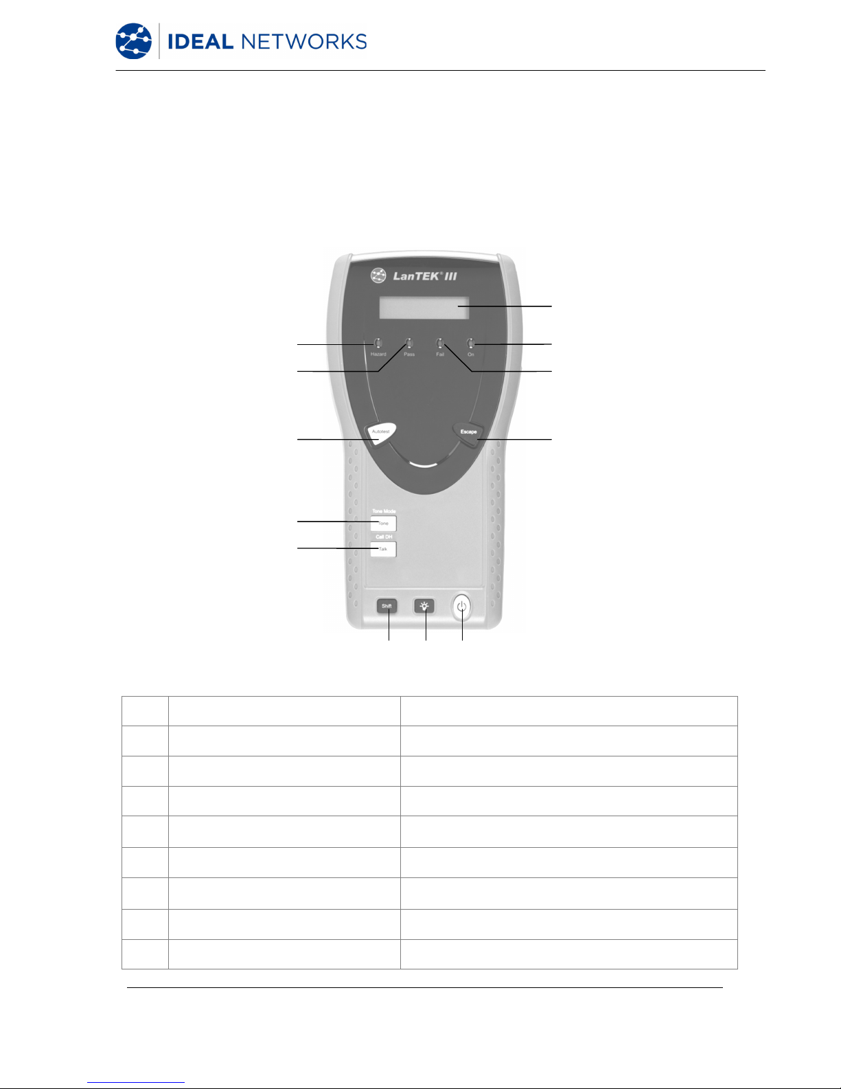
2.1.1 Controls and Ports/Connectors
Controls
Description
1 On/Off Power the Display handset (DH) on/off.
2 Dim Backlight Dim Backlight in two stages.
3 Shift Toggle key activities having dual functions.
4 Help / Language Open Help Menu / Open Language Selection
5 Talk / Call RH
Activate Talkset function / call Remote Handset
(RH).
6 Length / Analyze
Open Length Measurement / Open Diagnostics
Menu.
7 Wiremap / File
Open analyze function "Wiremap" / Open Job
List.
8
7
6
5
4
9
10
12
11
13
3 2 1
Fig. 1 The Display Handset (DH) Front view
LanTEK III 161809 Iss 2
User Manual Page10
Controls Description
8 Autotest
Direct execution of test run pre-programmed
for established standards.
9 TFT-Display
Display of menus, test results, graphs, activity
selection and function keys.
10
Function keys
F1 to F5 / F6 to F10
Select menu options displayed on screen.
11 Arrow Keys / Enter
Navigate menus on TFT Display / Enter key to
activate and edit the selected menu.
12 Escape
Abort and exit the current menu without
making changes.
13 Alphanumeric Keys Enter numbers, letters and special characters.
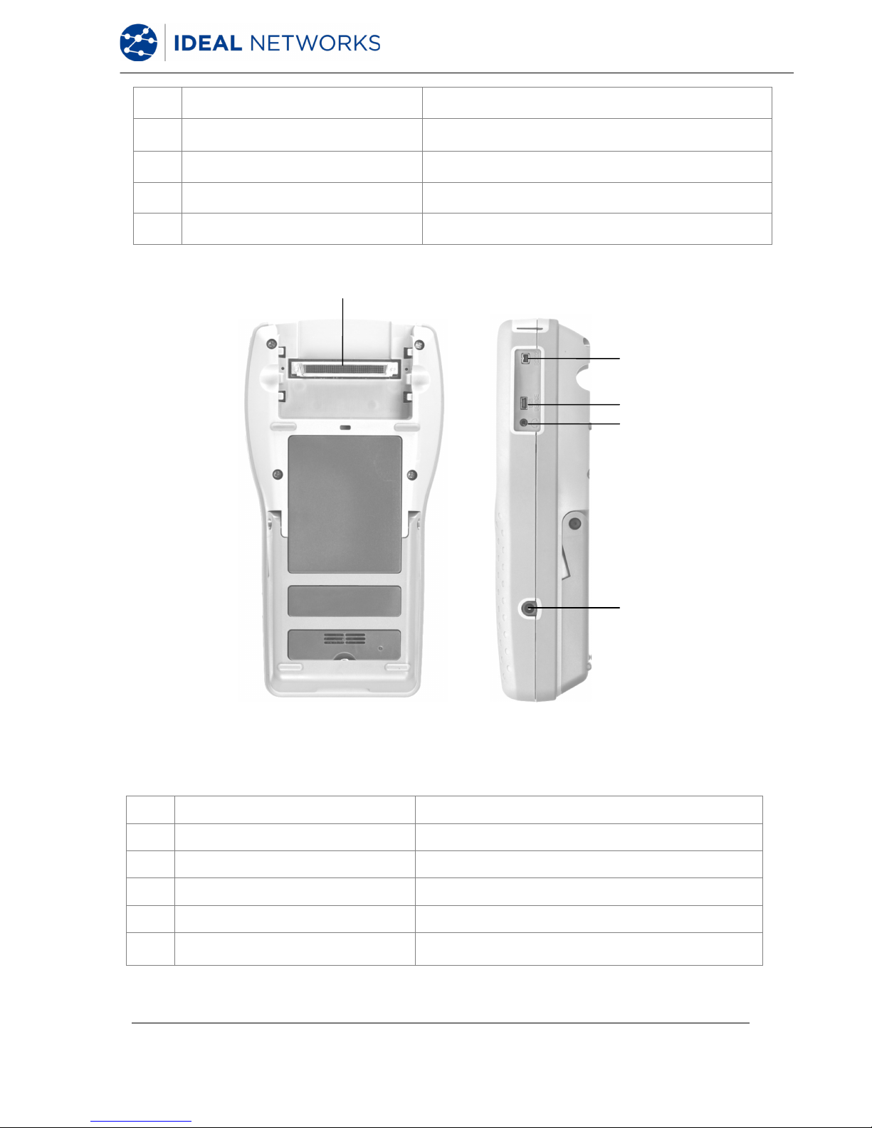
Ports/Connectors Description
14 Low-NEXT-Connector Connect a test adapter.
15 Service and Maintenance Jack Connection for service and maintenance work.
16 USB Port
Connect USB removable devices to transmit
data and to load Firmware-Updates.
17 USB Device Connect to a computer
18 Talkset Jack Connect a Talkset.
19 DC Input Jack
Connect an external power supply and charge
battery pack.
14
15
16
17
18
19
Fig. 2 The Display Handset (DH) Rear and side view
LanTEK III 161809 Iss 2
User Manual Page11
2.1.2 TFT Display
Ready screen appears on operational Display handset (DH).
1 2 3
18
17
16
15
14
13
4
5
6
7
8
12 11 10 9
Fig. 3 TFT Display
Display Description
1
Power supply and charge
state
Indicates battery operation or external power supply and
charge state of battery pack (%).
2 Talkset indicator Indicates whether talkset function is active.
3 Screen Title
Indicates that display handset (DH) or selected function
is ready.
4 Time and Date Displays the time and date.
5 Field calibration Select the field calibration.
6 Preferences Select the instrument preferences.
7 Toner Select the tone generator.
8 General Help Select the Help menu.
9 Cable Type Select or edit the cable type.
10 Fiber Select the fiber measurement.
11 Analyze Perform individual cable tests in real time.
12 Instrument Display the information on LanTEK®II Cable Certifier.
13 Function Name Displays the name of highlighted function.
14 Cable ID Select cable naming function.
15 Stored Tests Select file manager for the stored tests.
16 Job Name Display the current job name.
17 Test Standard Display the cable type selected for tests.
18 Records Number of records stored.
LanTEK III 161809 Iss 2
User Manual Page12
2.1.3 Function Keys F1 to F10
Function keys F1 to F5 have dual functions (F6 to F10). Pressing down the Shift key while
simultaneously pressing one of the function keys F1 to F5 will activate the 2nd function of
the function key (example: Shift + F4 equals function F8).
2.1.4 Soft Key
Soft keys indicate possible menu options at the bottom of the screen. To select the
according option, press the corresponding Function Key (F1 - F5) below the soft key.
The example below shows the setting of Timeout options by using the soft keys at the
bottom of the screen. The Value is set by Function Keys F1 (Increase) and F2 (Decrease).
Softkeys
Function keys
Fig. 4 Soft keys and function keys
LanTEK III 161809 Iss 2
User Manual Page13
2.2 The Remote Handset (RH)
The Remote handset (RH) works with the Display handset (DH) to perform autotests or
individual real time analyze tests. The Remote handset (RH) is located at the end of the
cable link and communicates with the Display handset (DH). To perform measurements, the
Remote handset (RH) is automatically activated by the Display handset (DH).
2.2.1 Controls and Ports/Connectors
9
8
7
5
4
10
11
12
6
3 2 1
Fig. 5 The Remote Handset (RH) Front view
Controls Description
1 On/Off Power the Remote handset (RH) on/off.
2 Dim Backlight Dim Backlight in two stages.
3 Shift Toggle key activities having dual functions.
4 Talk / Call DH
Activate Talkset function / call Remote handset
(RH).
5 Tone / Tone Mode Power the tone generator on/off.
6 Escape
Abort and exit the current action without making
changes.
7 Autotest Start the Autotest.
8 Pass LED Test result: Passed.
LanTEK III 161809 Iss 2
User Manual Page14
Controls Description
9 Hazard LED
Excessive line voltage (TELCO): Excessive
voltage at measurement input.
10 S/W-LCD Display Two line alphanumeric display
11 On LED The Remote Handset is on.
12 Fail LED Test result: Fail.
13
14
15
16
17
Fig. 6 The Remote Handset (RH) Rear and side view
Ports/Connectors Description
13 Low-NEXT-Connector Connect a test adapter.
14 Service and Maintenance Jack Connection for service and maintenance work.
15 USB Device Connect to a computer for firmware updates.
16 Talkset Jack Connect a Talkset.
17 DC Input Jack
Connect an external power supply and charge
battery pack.
LanTEK III 161809 Iss 2
User Manual Page15
2.3 Power Management
Both the Display (DH) and Remote (RH) handset use interchangeable rechargeable lithiumion battery packs (Li-ion).
• The Display (DH) and Remote (RH) handsets can be run on battery power for
approximately 18 hours. Actual battery power times depends on various factors,
such as operating time versus standby time, use of the display backlight, and
ambient temperature.
• When charge state of battery drops below the required voltage, a warning appears.
Tester automatically shuts down before testing results are affected.
• To save battery power, the Display (DH) and Remote (RH) handset automatically
power down after a certain period of inactivity.
• If the instrument will not be used for a prolonged time it is recommended that the
battery protection strips be inserted to conserve battery charge.
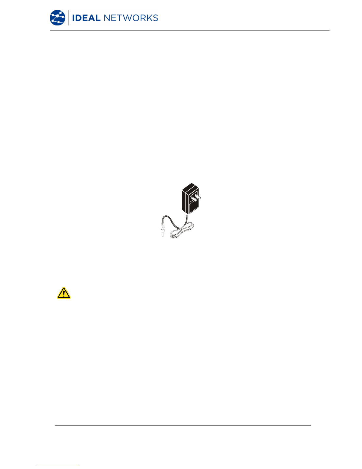
2.3.1 Operating the Display and Remote handset from AC Power
The Display (DH) and Remote (RH) handset can also be operated from an external DC
source (AC/DC adapter). The adapters are universally applicable.
Fig. 7 Adapter for LanTEK III DH and RH
When using the AC/DC adapter to power the handsets, please note that:
• Both handset batteries will receive a trickle charge.
• A power plug will appear in the upper left corner of the Display handset (DH).
CAUTION!
Only the adapter provided with the instrument shall be used. Other types of adapters
may cause damage to the tester.
NOTE:
Do not connect to AC power when testing shielded cables, as this may result in ground
loops which in turn can cause input protection warnings.

LanTEK III 161809 Iss 2
User Manual Page16
2.3.2 Battery Charging
The batteries of the Display (DH) and Remote (RH) handset are charged using the adapter.
It takes approximately 6-8 hours until the batteries in the instrument are fully charged. If the
batteries are charged externally, charge time is approximately 4 hours.
During recharging, the instrument is calibrated to the corresponding battery. This ensures
an accurate indication of the charge state at all times.
NOTE:
Charge time depends on charge state of battery.
When the battery is removed, the Display handset (DH) data and preferences are preserved
in the flash ROM by a coin cell lithium battery.
2.4 Talkset
The LanTEK®III Cable Certifier is designed for use with a talkset. This function allows
communication between the Display (DH) and Remote (RH) handset through an externally
attached microphone/headset. For this purpose, the Display (DH) and Remote (RH)
handset must be connected to the test adapters through a cable.
LanTEK III 161809 Iss 2
User Manual Page17
Chapter 3. Basics of the Cable Test
3.1 Testing of cables and relevant requirements
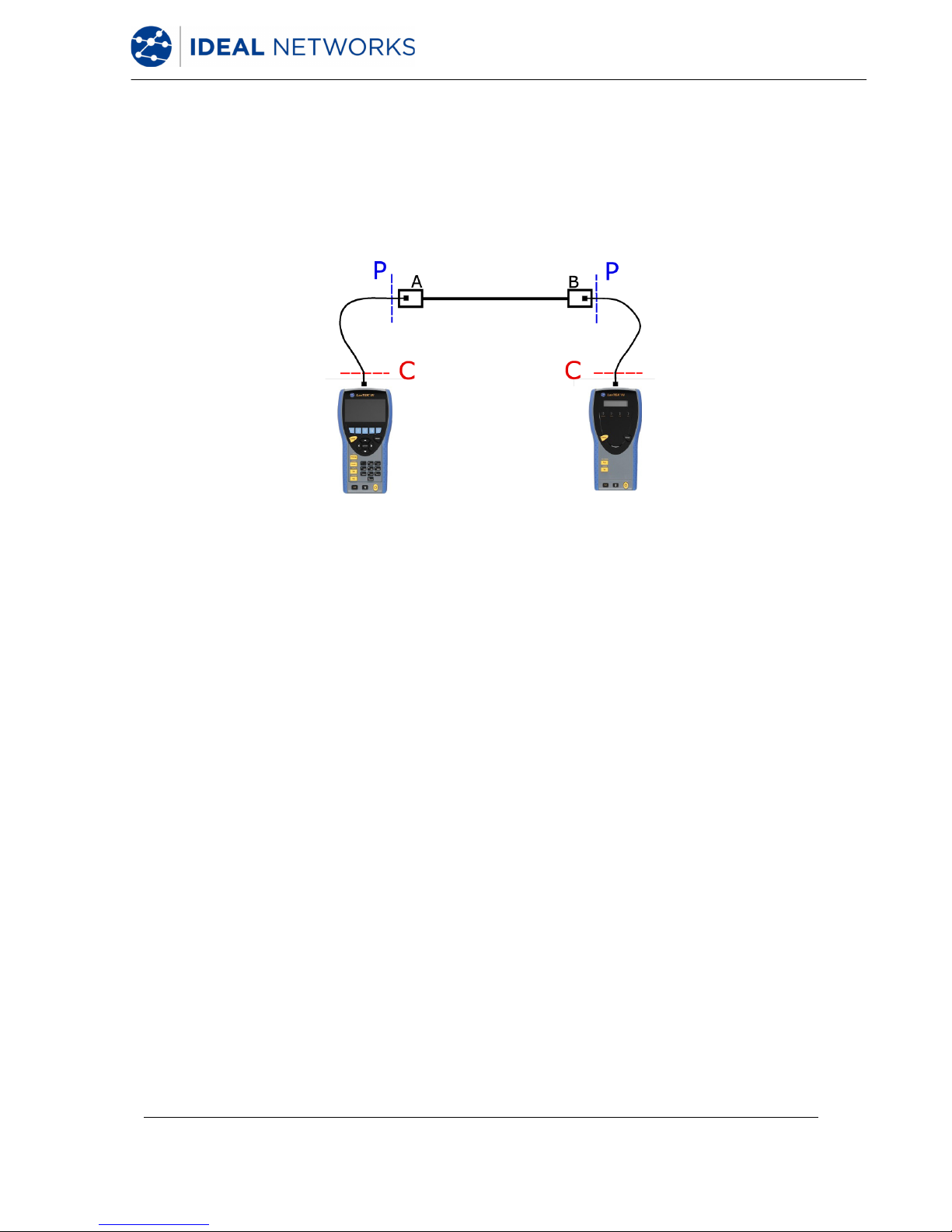
The following sections describe typical setup for permanent link and channel link testing.
Fig. 8 Illustration of test setup
The area marked with P indicates the typical test setup of a Permanent Link.
The area marked with C indicates the typical test setup of a Channel Link.
3.1.1 Setup for Permanent Link Test
The standards ANSI, EIA, TIA and ISO all differentiate between permanent link and channel
link on specifications for testing of communication networks. A permanent link consists of
up to 90 meters of horizontal cabling. (Maximum length limit applies to TIA standards only.)
The permanent link shown above serves to certify the installation of the horizontal cabling
before network connection and user hook-up. Adapters, patch cords and jumpers are
excluded from testing.
Depending on the link under test, Permanent Link testing with LanTEKIII requires different
Adapters:
• All RJ-45 cabling systems:
R161051
Permanent Link Adapter
R161050
PL Adapter Replacement Tips
• All non-45 cabling systems:
R161056
LanTEK® GG45-Adapter
R161054
LanTEK® TERA-Adapter
R161055
LanTEK® EC7-Adapter
NOTE:
Please visit www.idealnetworks.net for an
up to date full list of test Adapters.

LanTEK III 161809 Iss 2
User Manual Page18
3.1.2 Setup for Channel Link Test
A channel link includes all components of a cabling system. It consists of up to 90 meters
horizontal cabling, including patch cords, jumpers, and test adapters at each cable end. The
channel link shown above serves to certify the network installation, including the horizontal
cable line and patch cord.
Channel link testing requires different test Adapters depending on the link under test:
R161056
LanTEK® GG45-Adapter
R161054
LanTEK® TERA-Adapter
R161055
LanTEK® EC7-Adapter
R161053
LanTEK® Cat. 6A-Adapter for RJ-45
R161052
LanTEK® Cat. 6-Adapter for RJ-45
NOTE:
Please visit www.idealnetworks.net for an
up to date full list of test Adapters.
3.1.3 Setup for other Test Methods
Depending on the testing requirements other than permanent link and channel, LanTEKIII
offers various testing configurations:
• Coaxial testing
R161057
LanTEK® Coax-Kit
• Testing of End-to-End (E2E) , Device- or Direct Attach Links:
R160050
& R161053
LanTEK® Industrial Ethernet Kit
& LanTEK® Cat. 6A-Adapter for RJ-45
(both Adapters are required)
NOTE:
Please visit www.idealnetworks.net for an
up to date full list of test Adapters.
LanTEK III 161809 Iss 2
User Manual Page19
Chapter 4. Preferences
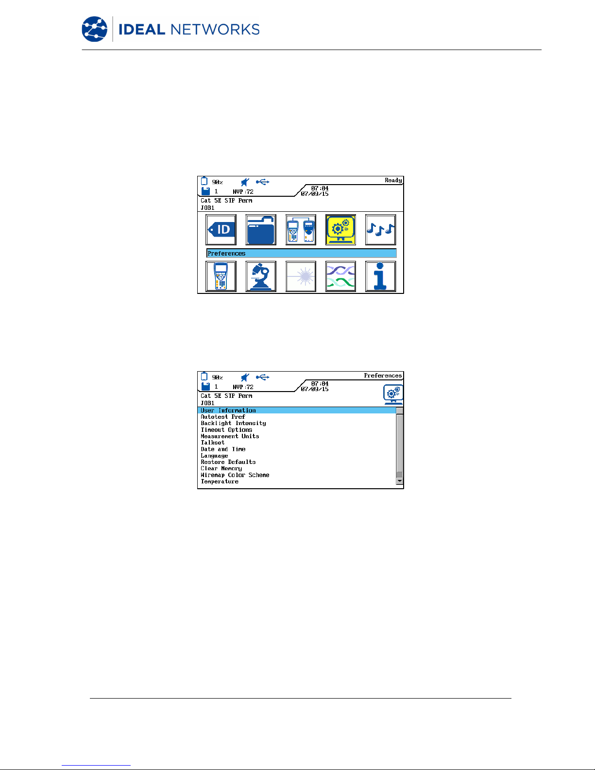
Most instrument configurations are set by using the "Preferences" menu.
4.1 Open Preferences
1. Use Arrow Keys to navigate to "Preferences" and press Enter.
Fig. 9 Open Preferences
2. Next, the instrument preferences can be set by using the listed menus.
Fig. 10 Preference Selection
4.2 User Information
This menu can be used to provide information on assigned Technician, Company and
Contractor.
1. Use Arrow Keys to navigate to "User Information" menu and press Enter.

LanTEK III 161809 Iss 2
User Manual Page20
Fig. 11 User Information
2. Use Arrow Keys to navigate to desired option Name, Company or Contractor.
3. Use Alphanumeric Keys to enter the desired information.
4. Make corrections to entries by using the soft keys (delete at cursor
position), (delete characters to the left of cursor), /
(insert alphanumeric characters at cursor position / overwrite highlighted entry).
5. Press Enter to save the information entered. Press Escape to exit the menu without
making changes.
4.3 Autotest Options
Use this menu to set Autotest options.
1. Use Arrow Keys to navigate to "Autotest Options" menu and press Enter.
Fig. 12 Autotest Options
2. Use Arrow keys to select the desired option.
3. Use soft key to activate or deactivate the selected option. An activated
option is indicated by the green box.
4. Press Enter to save the information entered. Press Escape to exit the menu without
making changes.
LanTEK III 161809 Iss 2
User Manual Page21
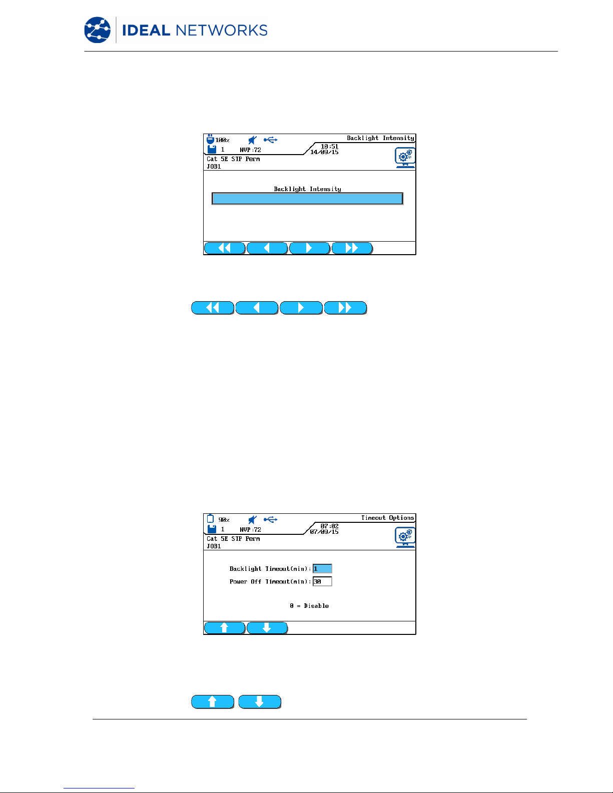
4.4 Contrast
Use this menu to set Dim Backlight on screen.
1. Use Arrow Keys to navigate to "Contrast" menu and press Enter.
Fig. 13 Contrast
2. Use soft keys to set backlight intensity.
3. Press Enter to save the information entered. Press Escape to exit the menu without
making changes.
4.5 Timeout Options
Use this menu to set the time after which backlight automatically dims and the LanTEK®III
Cable Certifier automatically shuts down when tester is not in use.
Default settings:
Backlight 1 minute
Tester 30 minutes
1. Use Arrow Keys to navigate to "Timeout Options" menu and press Enter.
Fig. 14 Timeout Options
2. Use Arrow keys to select the desired option.
3. Use soft keys to set the desired value.
LanTEK III 161809 Iss 2
User Manual Page22
4. Press Enter to save the information entered. Press Escape to exit the menu without
making changes
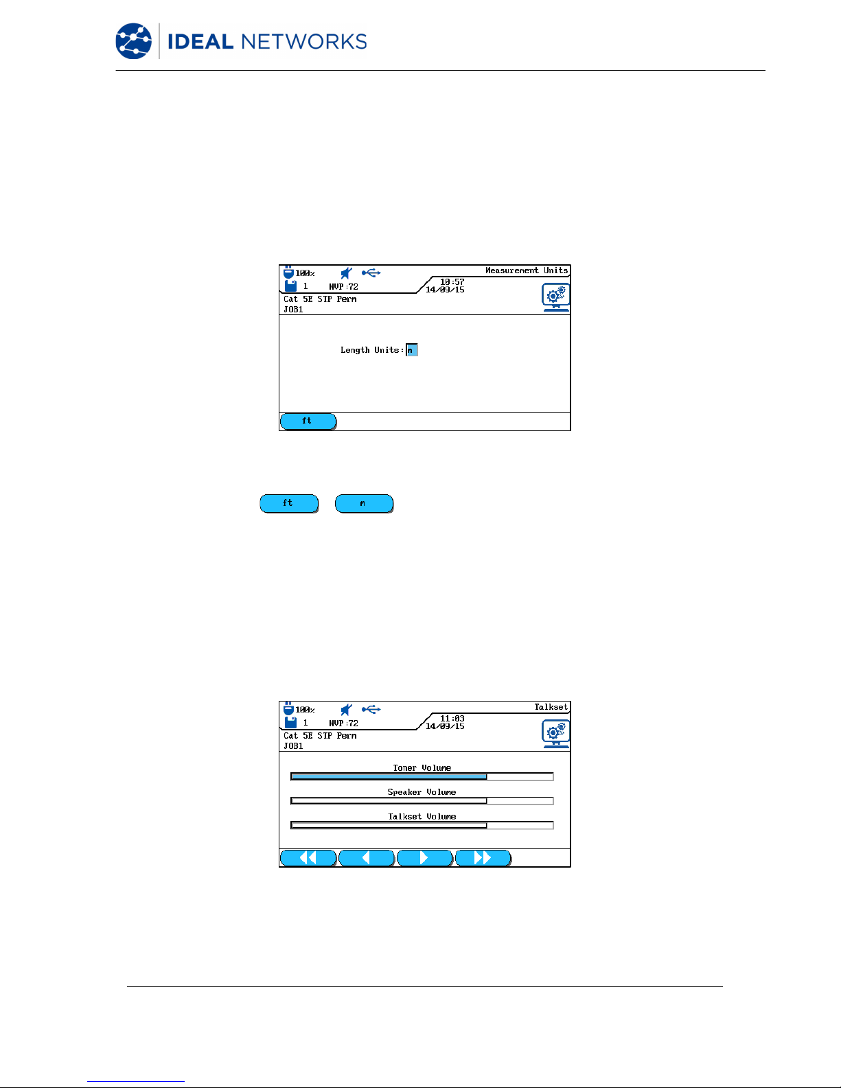
4.6 Measurement Units
Use this menu to specify the measurement unit for length measurements ft or m (foot or
meter). The default setting depends on the language selected.
1. Use Arrow Keys to navigate to "Measurement Units" menu and press Enter.
Fig. 15 Measurement Units
2. Use soft key / (foot / meter) to select the desired unit.
3. Press Enter to save the information entered. Press Escape to exit the menu without
making changes.
4.7 Talkset
Use this menu to set signal strength of tone generator, volume of internal speaker and
volume of talkset. Also use this menu to change the talkset mode.
1. Use Arrow Keys to navigate to "Talkset" menu and press Enter.
Fig. 16 Talkset
2. Use Arrow Keys to select the desired option.
LanTEK III 161809 Iss 2
User Manual Page23
3. On options Toner Volume, Speaker Volume or Talkset Volume, use soft keys
to set signal strength and volume.
4. Press Enter to save the information entered. Press Escape to exit the menu without
making changes.
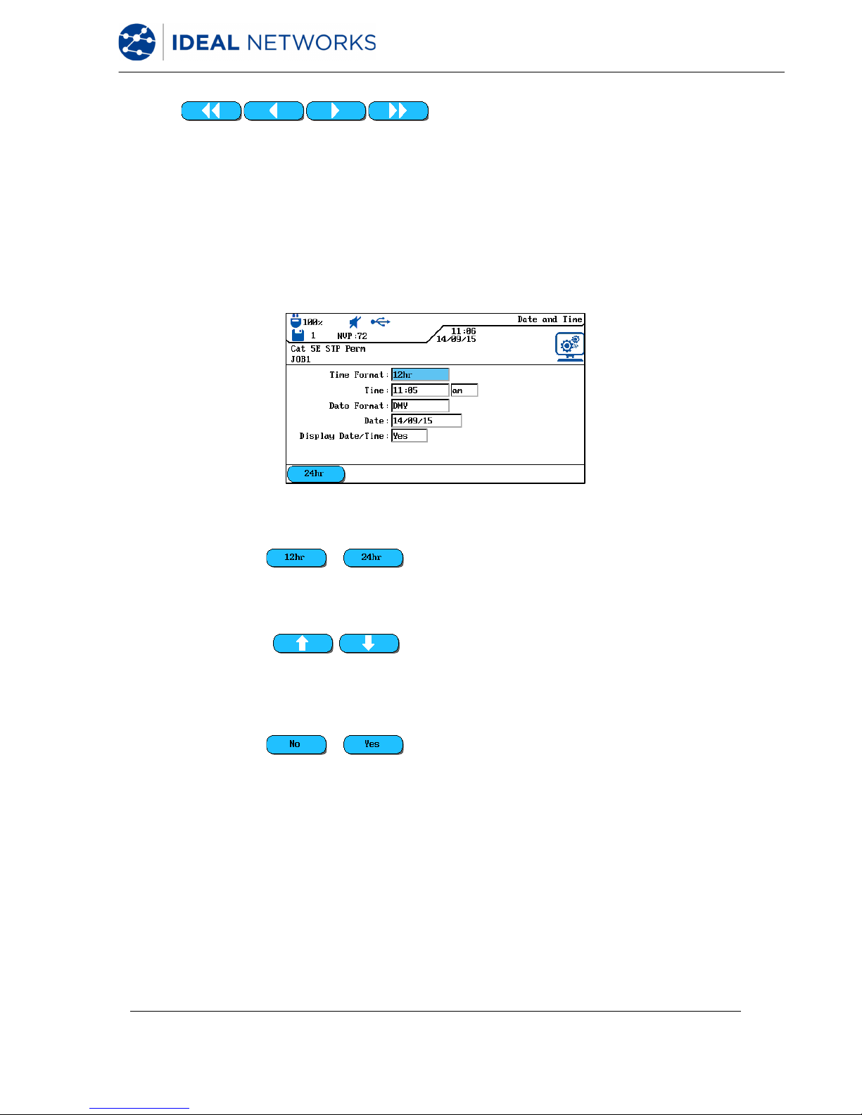
4.8 Date and Time
Accurate date and time settings are important for the reliable identification of records and
test reports.
1. Use Arrow Keys to navigate to "Date and Time" menu and press Enter.
Fig. 17 Date and Time
2. Use soft key / to set the desired Time format.
3. Use Arrow Keys to navigate to option Time.
4. Use Alphanumeric Keys to enter the time.
5. Use Arrow Keys to navigate to option Date Format.
6. Use soft keys to select the desired format MDY
(month/day/year), DMY (day/month/year) or YMD (year/month/day).
7. Use Arrow Keys to navigate to option Date.
8. Use Alphanumeric Keys to enter the date.
9. Use Arrow Keys to navigate to option Date/Time Display.
10. Use soft key / to select the desired setting.
11. Press Enter to save the information entered. Press Escape to exit the menu without
making changes.
 Loading...