

IDEAL Networks FiberTEK III User Manual

FiberTEK III

FiberTEK III Document 164802 Iss 4
User Manual Page 1
COPYRIGHT NOTICE
The information contained in this document is the property of IDEAL INDUSTRIES Ltd. and is
supplied without liability for errors and omissions. No part of this document may be
reproduced or used except as authorized by contract or other written permission from
IDEAL INDUSTRIES Ltd. The copyright and all restrictions on reproduction and use apply to
all media in which this information may be placed.
IDEAL INDUSTRIES Ltd. pursues a policy of continual product improvement and reserves the
right to alter without notice the specification, design, price or conditions of supply of any
product or service.
© IDEAL INDUSTRIES LTD. 2016
All rights reserved
Publication ref: 164802
Issue 4 - 02/2016
(Applies to LanTEK III software revision 3.067 onwards)
IDEAL INDUSTRIES LTD.
Stokenchurch House
Oxford Road
Stokenchurch
High Wycombe
Buckinghamshire
HP14 3SX UK
www.idealnetworks.net

FiberTEK III Document 164802 Iss 4
User Manual Page 2
Safety Precautions
WARNING!
NEVER look directly into the port of measuring adapter, at connector surface, open fiber ends or
into couplers. There is a risk of light emerging from the fiber that is not visible, which could
permanently damage your eyes.
If you are not sure whether the device is switched on or whether the fiber transmits light, for safety
reasons always assume that the device is active.
Handle bare fibers properly; there is a risk of injury from fiber splinters.
Protect your eyes when working with bare fibers; fiber splinters could permanently damage your
eyes.
Never let fiber scraps lie openly and never dispose of them loosely in normal waste containers;
there is a risk of injury from fiber splinters.
CAUTION!
When connecting the measuring adapter to a light-conducting line, the maximum measuring range
must be observed (see specifications of individual modules). Exceeding it could result in damages
to FiberTEK™ III modules.
NOTE:
Before connecting cable adapter to FiberTEK™ III adapter, ensure that the plugs of cable
connectors are clean.
Clean ferrules of measuring adapter only with dry, lint-free, non-abrasive materials.
The plugs can be cleaned with suitable fiber cleaning cloths or cleaning pens. IDEAL
recommends cleaning set #1219-00-1621025205 (2.5 mm) and 025204 (1.25 mm) to care
for the modules and patch cord.
Disclaimer
IDEAL INDUSTRIES, LTD. does not assume any liability for death, injury or damage to
equipment or property resulting from improper use of the battery packs.
IDEAL INDUSTRIES, LTD. will not be liable for consequential damages that may result from
tampering with the battery packs or charger or their use thereafter.
Subject to technical changes.
Environmental Protection
If you have any questions concerning these precautions, the operating instructions, or any
other concerns about the safe use and disposal of the battery packs used in LanTEK
®
III,
please contact a representative of IDEAL INDUSTRIES, LTD.

FiberTEK III Document 164802 Iss 4
User Manual Page 3
Information on the use of this Instruction Manual
The following symbols used in this manual indicate that the user should exercise particular
caution in order to prevent personal injury or damage to the FiberTEK™ III or the system
under test.
WARNING!
This symbol indicates potentially lethal voltages or dangerous situations. The life and/or
health of the person performing the activity or anybody in the vicinity is at risk.
CAUTION!
This symbol indicates that the relative activity could possibly harm the environment or
damage technical equipment.
NOTE:
Here you will find general notes, additional information, or support.
Typographical Conventions
• Boldface Refers to a button on LanTEK III Cable Certifier.
• Italics Refers to a menu option in this Operating Manual.
• Quotation marks " " identify a "Screen Message".

FiberTEK III Document 164802 Iss 4
User Manual Page 4
CONTENTS
Chapter 1.
Specifications ............................................................................................................ 5
Chapter 2. Product Description .................................................................................................. 8
2.1 Test Modules .................................................................................................................................................... 8
2.1.1 Controls, Ports, Indicators and Connectors .............................................................................. 8
2.2 Fiber Adapters ......................................................................................................................................... 10
2.3 Encircled Flux ........................................................................................................................................... 10
Chapter 3. Calibration ................................................................................................................. 11
3.1 Field Calibration ............................................................................................................................................ 11
3.2 Performing Field Calibration ............................................................................................................... 11
Chapter 4. Testing using FiberTEK™ III .................................................................................... 14
4.1 Test Setup According to Reference Method with Three Test Cords .................................... 14
4.2 Test Setup According to Reference Method with One Test Cord ..................................... 14
4.3 Set Autotest Pref..................................................................................................................................... 15
4.3.1 Selection of Fiber Test Standard ................................................................................................ 15
4.3.2 Selection of Refractive Index ........................................................................................................ 16
4.3.3 Selection of Fiber size and Wavelength .................................................................................. 16
4.3.4 Determine Loss Budget ................................................................................................................... 17
4.4 Evaluation of Autotest Results for Fibers (LWL) ...................................................................... 18
4.4.1 Passed/Failed Rating ....................................................................................................................... 18
4.4.2 Saving Current Autotest Results ................................................................................................. 18
4.4.3 Manual Saving of Autotest Results (Autosave off) ............................................................. 19
4.4.4 Working with Jobs ....................................................................................................................... 19
4.4.5 Display of Result Details ................................................................................................................. 19
Chapter 5. FiberTEK™ III Analyse Mode .................................................................................. 20
5.1.1 Continuous Run ................................................................................................................................. 20
5.1.2 Power Meter Mode ............................................................................................................................ 21

FiberTEK III Document 164802 Iss 4
User Manual Page 5
Chapter 1. Specifications
Operational Conditions
(unless specified
otherwise)
1. At 23 ±1 ºC unless otherwise specified.
2. After ten-minute warm-up time.
Testing speed
Autotest 8 seconds for each fiber / fiber pair (i.e. twice this for a BiDirectional test)
Input (Meter) connectors Universal with adaptors for FC, ST, SC and LC
Output (Source)
connectors
Universal with adaptors for FC, ST, SC and LC
Fiber type
9/125 µm, 50/125 μm and 62.5/125 μm
Source type and nominal
wavelength
MM LED: 850 nm LED and 1300 nm LED
SM Laser: 1310 nm and 1550 nm FP laser
Source wavelengths
MM: 850 ±20 nm
1300 nm -35 to +30 nm
SM: 1310 ±20 nm
1550 nm ±30 nm
Source spectral width
MM LED: Source spectral width (Full-Width Half-Maximum -
FWHM):
35 nm at 850 nm typical
80 nm at 1300 nm typical
Source power in light
source mode
MM 850 nm LED: -20 to -23 dBm nominal
With EF mode conditioner: -23 to -26 dBm nominal
MM 1300 nm LED: -15 to -20 dBm
With EF mode conditioner: -18 to -23 dBm
SM Laser: > -7 dBm
Source power stability
850, 1300 nm LED: ±0.25 dBm over 8 hours
1310, 1550 nm Lasers: ±0.25 dBm over 8 hours
Encircled Flux Compliance
Using optional external mode conditioner, complies withTIA-526-14B and IEC 61280-1-4 at the end of the cable
Length measurement
MM LED: 0 – 7,500 m of 50/125 or 62.5/125 µm fiber
SM Laser: : 0 - 20,000 m 9/125 µm fiber
Length measurement
accuracy
±1.5 m ±2% of length, 2 m minimum
Power meter type InGaAs detector
Power meter calibrated
wavelengths
MM: 850 nm, 1300nm
SM: 1310 nm, 1550 nm
Power measurement
range
0 to -55 dBm (850 nm)
0 to –60 dBm (1300/1310 nm and 1550 nm)
Power measurement
uncertainty (accuracy)
±0.25 dB at – 20 dBm, calibration performed with an FC adaptor
Measurement linearity
• 850 nm: target ±0.2 dB between 0 and -45 dBm, ± 0.25 dB below
-45 dBm
• 1300/1310 nm and 1550 nm: target ±0.2 dB between 0 and -55
dBm, ± 0.2 dB below -55 dBm
Display resolution
Power/attenuation: 0.01dB or dBm
Power W: 3 digits
1.00 to 9.99 nW
10.0 to 99.9 nW
100 to 999 nW
1.00 to 9.99 uW
10.0 to 99.9 uW
100 to 999 uW
Length: 0.1m / 0.5ft
Display update rate Approximately 2 updates per second on power meter function
FiberTEK III Document 164802 Iss 4
User Manual Page 6
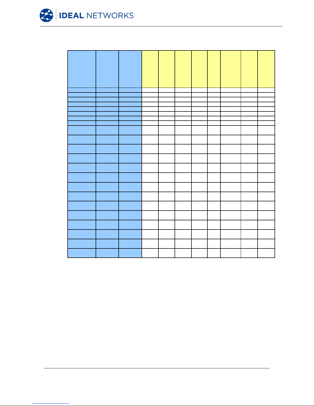
Standards
Organization
Classification or
Application
Fiber Type
Core size (um) /
wavelength (nm)
Max Link Channel
Loss (dB)
Max Connector
Insertion Loss (dB)
Max Splice
Insertion Loss (dB)
Min Connector
Return Loss (dB)
Maximum Distance
(m)
Min Operating
Distance (m)
(
50um/62.5um)
Max Fiber
Attenuation
(d
B/km)
Min Fiber
Bandwidth (MHz-
km
)
TIA 568-B.3 Horizontal link Multimode 62.5/850
n/s
0.75 0.3
>20 90 n/s 3.5 160
Horizontal link Multimode 50/850
n/s
0.75 0.3
>20 90 n/s 3.5 500
Horizontal link Multimode 62.
5/1300
n/s
0.75 0.3
>20 90 n/s 1.5 500
Horizontal link Multimode 50/1300
n/s
0.75 0.3
>20 90 n/s 1.5 500
Backbone Multimode 62.5/850
n/s
0.75 0.3
>20 2km n/s 3.5 160
Backbone Multimode 50/850
n/s
0.75 0.3
>20 2km n/s 3.5 500
Backbone Multimode 62.5/1300
n/s
0.75 0.3
>20 2km n/s 1.5 500
Backbone Multimode 50/1300
n/s
0.75 0.3
>20 2km n/s 1.5 500
Horizontal link Single mode 9/1310
n/s
0.75 0.3
>26 90 n/s 1.0 n/a
Horizontal link Single mode 9/
1550
n/s
0.75 0.3
>26 90 n/s 1.0 n/a
Backbone (ISP) Single mode 9/1310
n/s
0.75 0.3
>26 3km n/s 1.0 n/a
Backbone (ISP) Single mode 9/
1550
n/s
0.75 0.3
>26 3km n/s 1.0 n/a
Backbone (OSP)
Single mode 9/1310
n/s
0.75 0.3
>26 3km n/s 0.5 n/a
Backbone (OSP)
Single mode 9/1550
n/
s
0.75 0.3
>26 3km n/s 0.5 n/a
OF-300 OM1
50 or
62.5/1300
1.95
0.75 ea/
1.5 total
0.3
>20 n/
s 300 1.5 500
OF-300 OM2
50 or
62.5/850
2.55
0.75 ea/
1.5 total
0.3
>20 n/
s 300 3.5 500
OF-300 OM2
50 or
62.5/1300
1.95
0.75 ea/
1.5 total
0.3
>20 n/
s 300 1.5 500
OF-300 OM3 50/850
2.55
0.75 ea/
1.5 total
0.3
>20 n/
s 300 3.5 1500
OF-300 OM3 50/
1300
1.95
0.75 ea/
1.5 total
0.3
>20 n/
s 300 1.5 500
OF-300 OS1
9/1310 or
1550
1.80
0.75 ea/
1.5 total
0.3
>35 n/
s 300 1.0 n/s
OF-500 OM1
50 or
62.5/850
3.25
0.75 ea/
1.5 total
0.3
>20 n/
s 500 3.5 200
OF-500 OM1
50 or
62.5/1300
2.25
0.75 ea/
1.5 total
0.3
>20 n/
s 500 1.5 500
Summary of Fiber Optic Cabling Standards & Application Requirements
ISO 11801
Generic
C
abling
ISO 11801
Generic
C
abling
Generic
Cabling
FiberTEK III Document 164802 Iss 4
User Manual Page 7
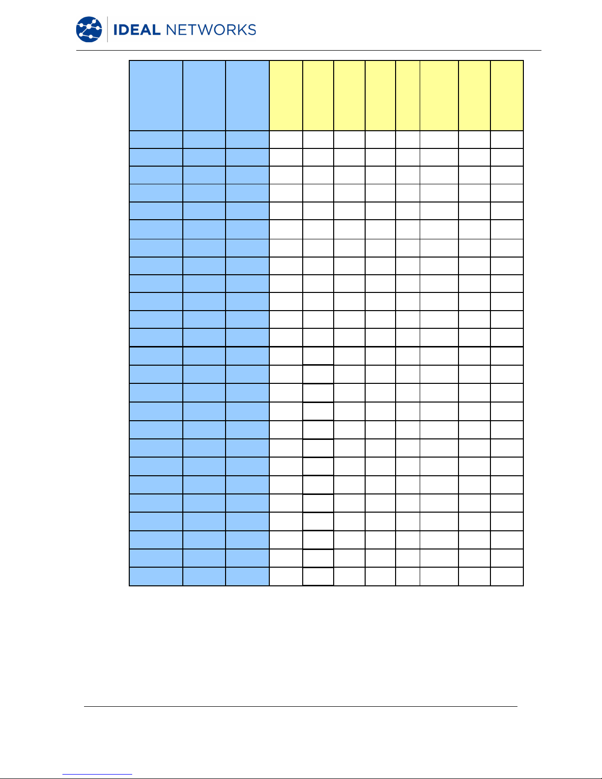
Standards
Organization
Classification or
Application
Fiber Type
Core size (um) /
wavelength (nm)
Max Link Channel
Loss (dB)
Max Connector
Insertion Loss (dB)
Max Splice
Insertion Loss (dB)
Min Connector
Return Loss (dB)
Maximum Distance
(m)
Min Operating
Distance (m)
(50um/62.5um)
Max Fiber
Attenuation
(dB/km)
Min Fiber
Bandwidth (MHz-
km)
OF-500 OM2
50 or
62.5/850
3.25
0.75 ea/
1.5 total
0.3
>20 n/s 500 3.5 500
OF-500 OM2
50 or
62.5/1300
2.25
0.75 ea/
1.5 total
0.3
>20 n/s 500 3.5 500
OF-500 OM3 50/850
3.25
0.75 ea/
1.5 total
0.3
>20 n/s 500 3.5 1500
OF-500 OM3 50/130
2.25
0.75 ea/
1.5 total
0.3
>20 n/s 500 1.5 500
OF-500 OS1
9/1310 or
1550
2.00
0.75 ea/
1.5 total
0.3
>35 n/s 500 1.0 n/a
OF-2000 OM1
50 or
62.5/850
8.50
0.75 ea/
1.5 total
0.3
>20 n/s 2km 3.5 200
OF-2000 OM1
50 or
62.5/1300
4.50
0.75 ea/
1.5 total
0.3
>20 n/s 2km 1.5 500
OF-2000 OM2
50 or
62.5/850
8.50
0.75 ea/
1.5 total
0.3
>20 n/s 2km 3.5 500
OF-2000 OM2
50 or
62.5/1300
4.50
0.75 ea/
1.5 total
0.3
>20 n/s 2km 1.5 500
OF-2000 OM3 50/850
8.50
0.75 ea/
1.5 total
0.3
>20 n/s 2km 3.5 1500
OF-2000 OM3 50/130
4.50
0.75 ea/
1.5 total
0.3
>20 n/s 2km 1.5 500
OF-2000 OS1
9/1310 or
1550
3.50
0.75 ea/
1.5 total
0.3
>35 n/s 2km 1.0 n/a
IEEE 802.3 10Base-FL
Multimode/
OM1-OM2
62.5/850
12.50
0.75 ea/
1.5 total
n/s
>20 2km 0 3.75 160
10Base-FL
Multimode/
OM1-OM3
50/850
12.50
0.75 ea/
1.5 total
n/s
>20 1.5km 0 3.75 160
100Base-FX
Multimode/
OM1-OM3
62.5 or
50/1300
11.00
0.75 ea/
1.5 total
n/s
n/s 2km 0 3.75 500
1000Base-SX
Multimode/
OM1-OM2
62.5/850
2.33
0.75 ea/
1.5 total
n/s
>20 n/s 220 3.75 160
1000Base-SX
Multimode/
OM2-OM3
62.5/850
2.53
0.75 ea/
1.5 total
n/s
>20 n/s 275 3.75 200
1000Base-SX
Multimode/
OM1-OM3
50/850
3.25
0.75 ea/
1.5 total
n/s
>20 n/s 500 3.5 400
1000Base-SX
Multimode/
OM2-OM3
50/850
3.43
0.75 ea/
1.5 total
n/s
>20 n/s 550 3.5 500
1000Base-LX
Multimode/
OM1-OM2
62.5/1300
2.32
0.75 ea/
1.5 total
n/s
>20 n/s 550 1.5 500
1000Base-LX
Multimode/
OM1-OM2
50/1300
2.32
0.75 ea/
1.5 total
n/s
>20 n/s 550 1.5 400/500
1000Base-LX
Singlemode/
OS1
9/1310
4.50
0.75 ea/
1.5 total
n/s
>26 n/s 5km 0.5 n/a
10GBase-SR
MultimodeOM1
62.5/850
2.60
0.75 ea/
1.5 total
n/s
>20 n/s 26 3.5 160
10GBase-SR
MultimodeOM1
62.5/805
2.50
0.75 ea/
1.5 total
n/s
>20 n/s 33 3.5 200
10GBase-SR
Multimode/
OM2-OM3
50/850
2.20
0.75 ea/
1.5 total
n/s
>20 n/s 66 3.5 400
ISO 11801
Generic
Cabling
 Loading...