

CS Series With Cree SmartCast™ Technology
CS14™, CS18™ LED Linear Luminaire
8' and 4' Luminaires
IMPORTANT SAFEGUARDS
When using electrical equipment, basic safety precautions should
always be followed including the following:
READ AND FOLLOW ALL SAFETY INSTRUCTIONS
1. DANGER- Risk of shock- Disconnect power before installation.
DANGER – Risque de choc – Couper l’alimentation avant
l’installation.
2. This luminaire must be installed in accordance with the NEC or your
local electrical code. If you are not familiar with these codes and
requirements, consult a qualied electrician.
Ce produit doit être installé conformément à NEC ou votre code
électrique local. Si vous n’êtes pas familier avec ces codes et ces
exigences, veuillez contacter un électricien qualié.
3. Check to make sure that all the xture connections have been properly
made and the xture is grounded to avoid potential electrical shocks.
4. Do not handle energized module with wet hands or when standing on
wet or damp surfaces, or in water.
5. Suitable for damp locations.
Convient aux emplacements humides.
SAVE THESE INSTRUCTIONS FOR FUTURE
REFERENCE
WARNING - Maximum connected load with a single power supply shall
not exceed maximum ampacity rating of #12 AWG THHN through-wire
conductors. Use only lighting controls with relay or FET-based outputs,
or lighting controls with neutral connection. Reference www.cree.com/
lighting for recommended dimming control options. Avoid handling
LEDs directly. Not intended for use in environments containing airborne
corrosive agents such as chemical solvents, cleaners, or cutting uids
INSTALLATION INSTRUCTIONS
INSTRUCTIONS D’INSTALLATION
• The CS Series LED linear luminaire is for
suspended, with cable or threaded rod, or
surface mount applications using appropriate
tong hangers. Reference individual mounting
accessory installation instructions for specific
mounting types.
• Designed for use in 120–277V, 50-60 Hertz
protected circuit (fuse box, circuit breaker) and
supply wire shall be rated minimum 12AWG,
600V, 90 C rated).
TO I NSTALL :
1
2
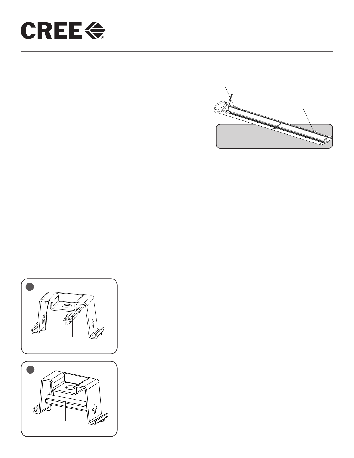
Cross Brace
Cross Brace
NOTE: When removing luminaire from packaging, keeping
protective plastic wrap on fixture during installation and
construction.
FOR PLASTIC TONG HANGERS (TM):
NOTE: Center hole can accommodate 1/2" diameter rod
maximum.
STEP 1:
Remove cross brace and securely insert it into the “+” shaped
openings in the plastic tong hanger. See Figures 1 & 2. For single
units or end row fixtures, place the plastic tong hanger assembly
into center spine no more than 18" from each end of fixture and
twist approximately 45 degrees until the plastic tong hanger
assembly is securely in place and approximately 90 degrees to
the length of fixture. See Figure 3.
STEP 2:
For continuous row installation, continue with next fixture using
a minimum of one tong hanger per unit. Each bracket should be
properly snug and be difficult to slide along the back spine.
1 of 4 LPN00212X0003A7
FOR OPTIONAL METAL TONG HANGERS
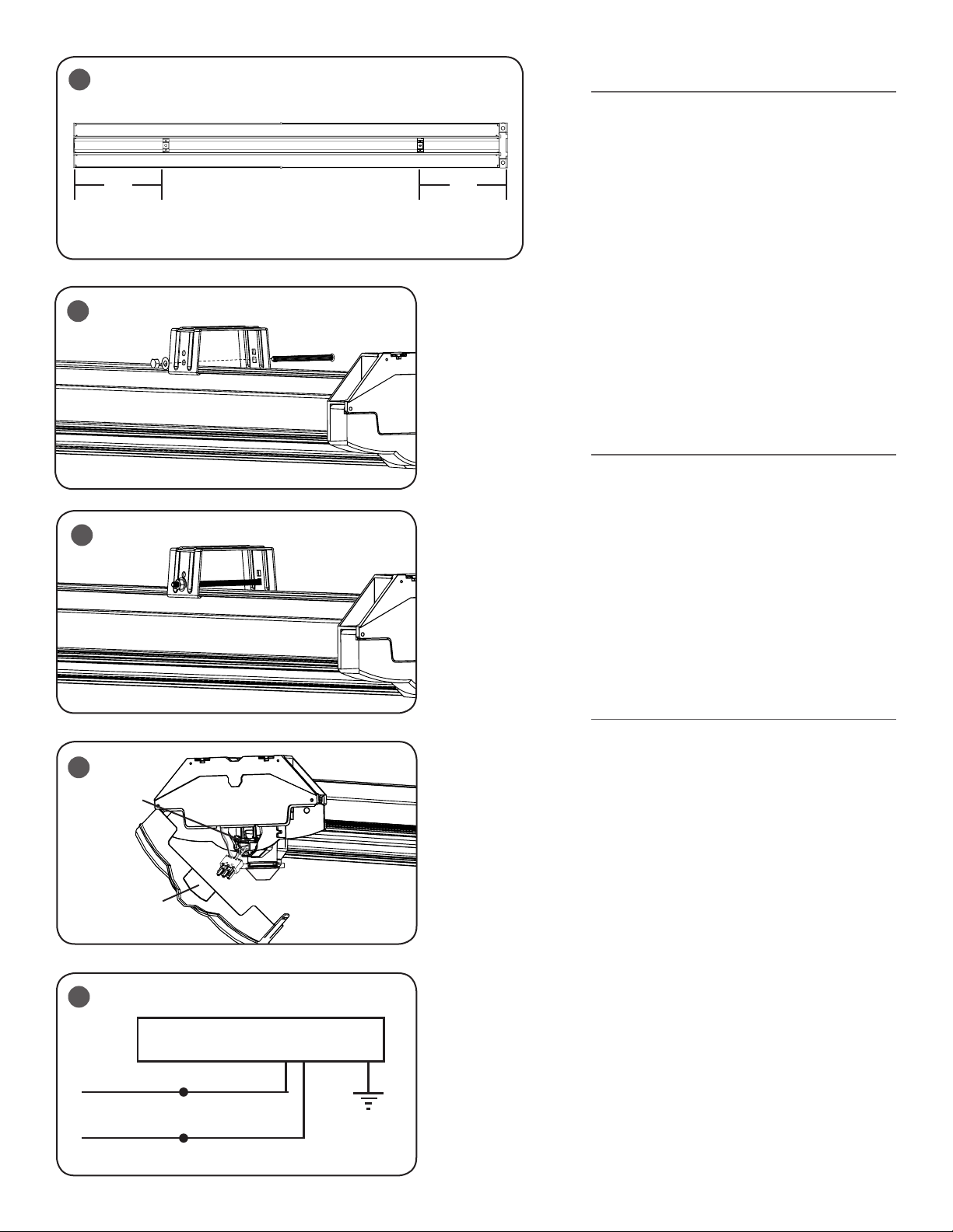
3
18"18"
4
(TMM):
NOTE: Center hole can accommodate 3/8" diameter
rod maximum. Recommended for surface mount
installations.
STEP 1:
For single units or end row fixtures, place metal
tong hanger bracket over center spine no more
than 18" from each end of fixture. See Figure
3. Insert supplied bolt through the metal tong
hanger and secure with lock washer and nut,
tightening to secure spine to the metal tong
hanger. See Figure 4 & 5. Additional suspension
points are optional depending on field
conditions.
STEP 2:
For continuous row installation, continue with
next fixture using a minimum of one tong hanger
per unit. Each bracket should be properly snug
and be difficult to slide along the back spine.
FOR SUSPENDED MOUNTING:
STEP 1:
For suspended individual mount luminaires, one
Power Feed with Cable Support and one Cable
Support is required.
5
STEP 2:
For continuous row installation, begin row
(luminaire #1) with one Power Feed with
Cable Support and one Cable Support. Each
subsequent luminaire, one Cable Support is
required; not to exceed 18" from end of luminaire.
For environments that do not allow proper
spacing of cable support, Unistrut may be
required, supplied by others.
6
AC Power
Compartment
Knockout
7
LINE
NEUTRAL
ELECTRICAL CONNECTIONS
STEP 1:
For powering the fixture(s), open wiring
compartment swing door on end of the luminaire
and extend wiring in preparation for connections.
See Figure 6.
STEP 2:
Bring AC feed into wiring compartment
through conduit hole on left side. Remove black
connector and terminate leads according to local
codes.
STEP 3:
Make electrical connections referring to Figure 7.
STEP 4:
Close swing door assuring no leads are pinched.
See Figure 6.
DRIVER ASSEMBLY
BLACK
WHITE
2 of 4 LPN00212X0003A7
 Loading...