

Ideal Lighting CREE Lighting PLM Users Manual
Wireless Plug Load Controller
Wireless Plug Load Controller with SmartCast® Technology
Includes: CPLC-JB-CWC
When using electrical equipment, basic safety precautions should always be
IMPORTANT SAFEGUARDS
followed including the following:
READ AND FOLLOW ALL SAFETY
INSTRUCTIONS
1. DANGER- Risk of shock- Disconnect power before installation.
DANGER – Risque de choc – Couper l’alimentation avant l’installation.
2. Must be installed in accordance with the NEC or your local electrical
code. If you are not familiar with these codes and requirements, consult a
qualied electrician.
Ce produit doit être installé conformément à NEC ou votre code électrique
local. Si vous n’êtes pas familier avec ces codes et ces exigences, veuillez
contacter un électricien qualié.
3. Indoor use only and Suitable for Damp Locations.
Pour usage interieur seulement et convient aux emplacements humides.
4. This equipment should be installed and operated with a minimum distance
20cm between the radiator and your body.
L’équipement doit etre installe d’une facon qu’une distance minimum de 20cm
soit maintenue entre l’emetteur et toute partie du corps.
SAVE THESE INSTRUCTIONS FOR
FUTURE REFERENCE
NOTE:
• Not for use with equipment that requires constant power or equipment that
presents a hazard if automatically energized. Devices requiring soft shutdown
(such as computers) or other power related requirements (such as projectors,
DVRs or Clocks) may not be compatible.
INSTALLATION INSTRUCTIONS
• Suitable for use in other Environmental Air Space
(Plenums) in accordance with section 300.22,(c) of the
National Electrical Code.
• Voltage: 120 VAC, 60Hz.
• AC Load Type:
• 20 A Resistive load @ 120VAC
• 1 HP Motor load @ 120VAC
• 20A Standard ballast load @ 120VAC
• 20A Tungsten (incandescent) load @ 120VAC
• 20A General use @ 120VAC
• Contact Closure Output (CCO) load:
• Up to 24VDC, 0.5A resistive load on dry contacts
(N/O, COM, N/C)
• For connection to Class 2 circuit only.
• Install using a junction box that has a 1/2" knockout.
1
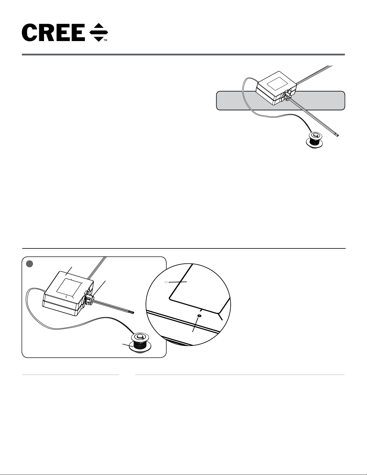
Wireless Plug
Load Controller
This End Insert into
Junction Box
Occupancy
Sensor
UNIT DESCRIPTION
The Wireless Plug Load Controller is used
to control 120V AC receptacles in response
to attached occupancy sensor and through
wireless commands from other Cree
Smartcast® Technology devices. The Wireless
Plug Load Controller also offers contact
closure output (CCO) to control third party
equipment.
1 of 5
Blue LED
Placement
Test/Reset
Button Inside
INSTALLATION
NOTE: For ease of installation, Cree
recommends using a Junction Box with a ½"
knockout.
STEP 1:
Disconnect power to circuit by turning circuit
breaker OFF before installation.
STEP 2:
Remove Junction Box cover.
STEP 3:
Remove knockout and firmly install plastic
relay box into Junction Box until it snaps and
is securely attached
Blue LED is Inside the Relay Box, Light will
Shine Through at the LED Placement Shown
Below.
STEP 4:
Strip existing Junction Box wires ½".
STEP 5:
Make wiring connection per the Electrical
Connections section.
STEP 6:
Attach Junction Box cover.
STEP 7:
Install sensor into ceiling by drilling a 2" hole
into the ceiling.
LPN00544X0001A0_C
2
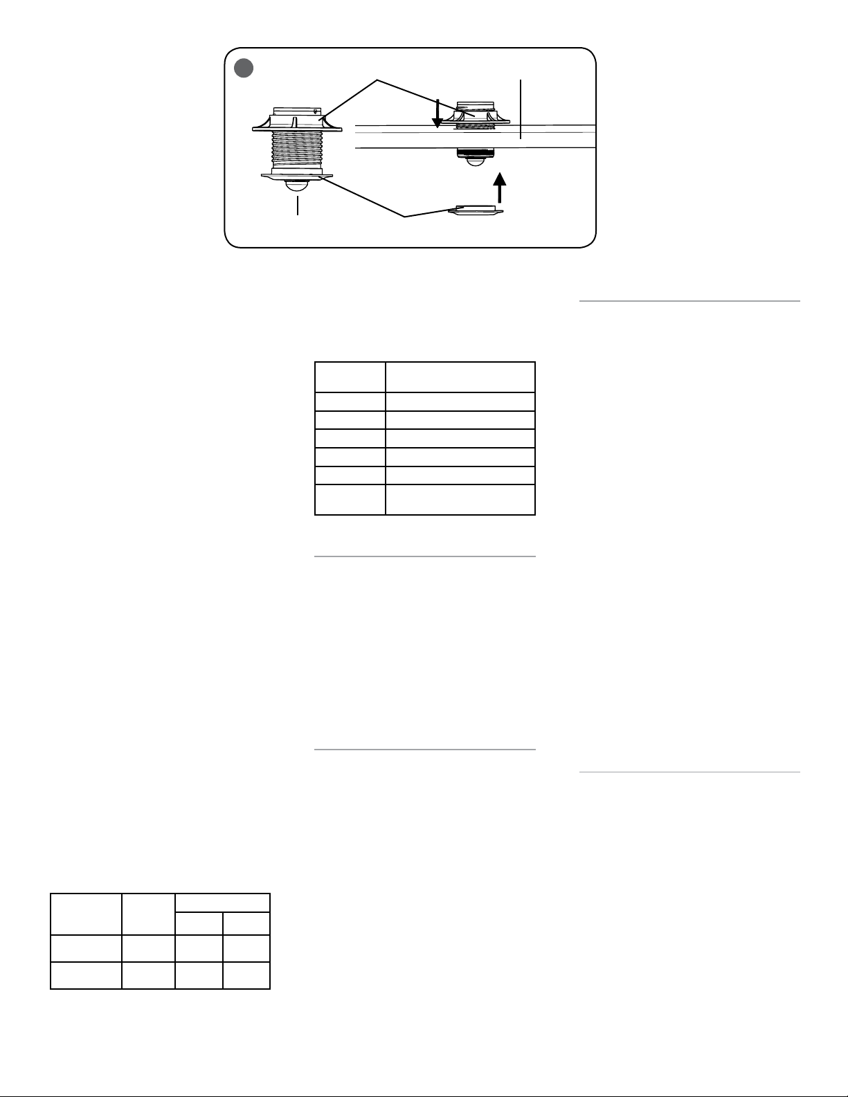
Large Trim Ring
Ceiling
STEP 8:
Unscrew the small trim ring near the sensor
and place sensor assembly through the
ceiling. See Figure 2.
STEP 9:
Secure the sensor assembly by screwing the
small trim ring removed in Step 8 back onto
the sensor assembly. Tighten the larger trim
ring above the ceiling until it is snugged tight
against the ceiling. See
Figure 2.
STEP 10:
Switch the circuit breaker ON.
STEP 11:
The blue LED should repeat a two blink
sequence. If the blue LED is blinking
but does not respond with the two-blink
sequence, please follow the RESET
instructions to return the Wireless Plug Load
Controller to factory defaults.
STEP 12:
Verify the LOAD wiring with the following
TEST instructions:
• Press and hold the Test/Reset button
for 5 sec then release. The blue LED
should respond with a five-blink
sequence. Once TEST mode has been
entered, LOAD enters State 1. See
Figure 1.
• Press and hold Test/Reset button for
1 sec then release to transition to
the next state. The sequence repeats
after State 2. Please refer to the load
table below.
• To exit test mode at any time, press
and hold the Test/Reset button for
5 sec then release. The five-blink
sequence ends when TEST mode is
exited.
Plug Load
Controller
State
State 1 Off Open Closed
State 2 On Closed Open
LOAD
STATUS
CCO Status
N/O N/C
2 of 5
Occupancy
Sensor
Small Trim Ring
STEP 13:
Perform commissioning using Cree
Configuration Tool (OneButton® Setup). The
table below shows different blink patterns
and their meanings.
Status LED
indicator
1 Blink Normal mode
2 Blink Ready for OneButton
3 Blink OneButton
4 Blink Select mode
5 Blink TEST Mode
Solid ON or
OFF
Operating Mode
®
Setup in process
Error- contact Cree Customer
Service
RESET (FACTORY DEFAULTS)
STEP 1:
Press and hold Test/Reset button until the
LED flashes fast (approximately 30 seconds).
STEP 2:
Release the Test/Reset button for 1 second
(Fast flashing continues). Press and hold
Test/Reset for 1 second until fast flashing
stops. If the blue LED does not respond with
the two-blink sequence, please repeat the
RESET procedure.
TROUBLESHOOTING:
Out of the box, if the LOAD does not turn on
when power is applied:
1. Check blue LED to make sure it is
blinking. If Blue LED is on solid or off,
call Cree Customer Service.
2. If not in two blink mode, then
perform a RESET (See RESET
section).
3. If in two blink mode, then perform
TEST mode (See Step 12)
4. If TEST mode fails, check wiring with
power off.
5. If wiring is correct and the LOAD is
still off, call Cree Customer Service.
®
Setup
FCC NOTICE
This device complies with Part 15 of the
FCC Rules. Operation is subject to the
following two conditions: (1) this device
may not cause harmful interference, and
(2) this device must accept any interference
received, including interference that may
cause undesired operation. Any changes or
modifications not expressly approved by the
party responsible for compliance could void
the user’s authority to operate the device.
This device has been tested and found to
comply with the limits for a Class A digital
device, pursuant to Part 15 of the FCC
Rules. These limits are designed to provide
reasonable protection against harmful
interference when the device is operated
in a commercial environment. This device
generates, uses, and can radiate radio
frequency energy and, if not installed and
used in accordance with the instruction
manual, may cause harmful interference
to radio communications. Operation of this
device in a residential area is likely to cause
harmful interference in which case the user
will be required to correct the interference at
his own expense.
In addition, this device complies with ICES005 of the Industry Canada (IC) Regulations.
INDUSTRY CANADA STATEMENT
This device complies with Industry Canada
licence-exempt RSS standard(s). Operation
is subject to the following two conditions: (1)
this device may not cause interference, and
(2) this device must accept any interference,
including interference that may cause
undesired operation of the device. In
addition, this device complies with ICES-005
of the Industry Canada (IC) Regulations.
Le présent appareil est conforme aux CNR
d’Industrie Canada applicables aux appareils
radio exempts de licence. L’exploitation est
autorisée aux deux conditions suivantes : (1)
l’appareil ne doit pas produire de brouillage,
et (2) l’utilisateur de l’appareil doit accepter
tout brouillage radioélectrique subi,
même si le brouillage est susceptible d’en
compromettre le fonctionnement.
LPN00544X0001A0_C
 Loading...