

Cree Wireless Wall Controls With SmartCast™ Technology
IMPORTANT SAFEGUARDS
When using electrical equipment, basic safety precautions should always be
followed including the following:
READ AND FOLLOW ALL SAFETY INSTRUCTIONS
1. Before installing wall controls turn off the power at the circuit breaker.
2. These wall controls must be installed in accordance with the national and
local building codes and electrical wiring codes including wiring methods
and wiring connections. If you are not familiar with these codes and
requirements, consult a qualied electrician.
3. Indoor use only and suitable for damp locations.
4. Any changes or modications to these devices not explicitly approved by
manufacturer could void your authority to operate this equipment.
SAVE THESE INSTRUCTIONS FOR FUTURE REFERENCE
• Voltage: 120-277V, 60Hz
• Depth in Wall: 1.5"
• For ease of installation, Cree recommends the use of a deep wall box.
Wireless Dimmer and Wireless Switch
Includes: CWD-CWC-XX and CWS-CWC-XX
INSTALLATION INSTRUCTIONS
WIRELESS DIMMER
CWD-CWC
WIRELESS SWITCH
CWS-CWC
1
On
Off
Dimming
Up
LED
Dimming
Down
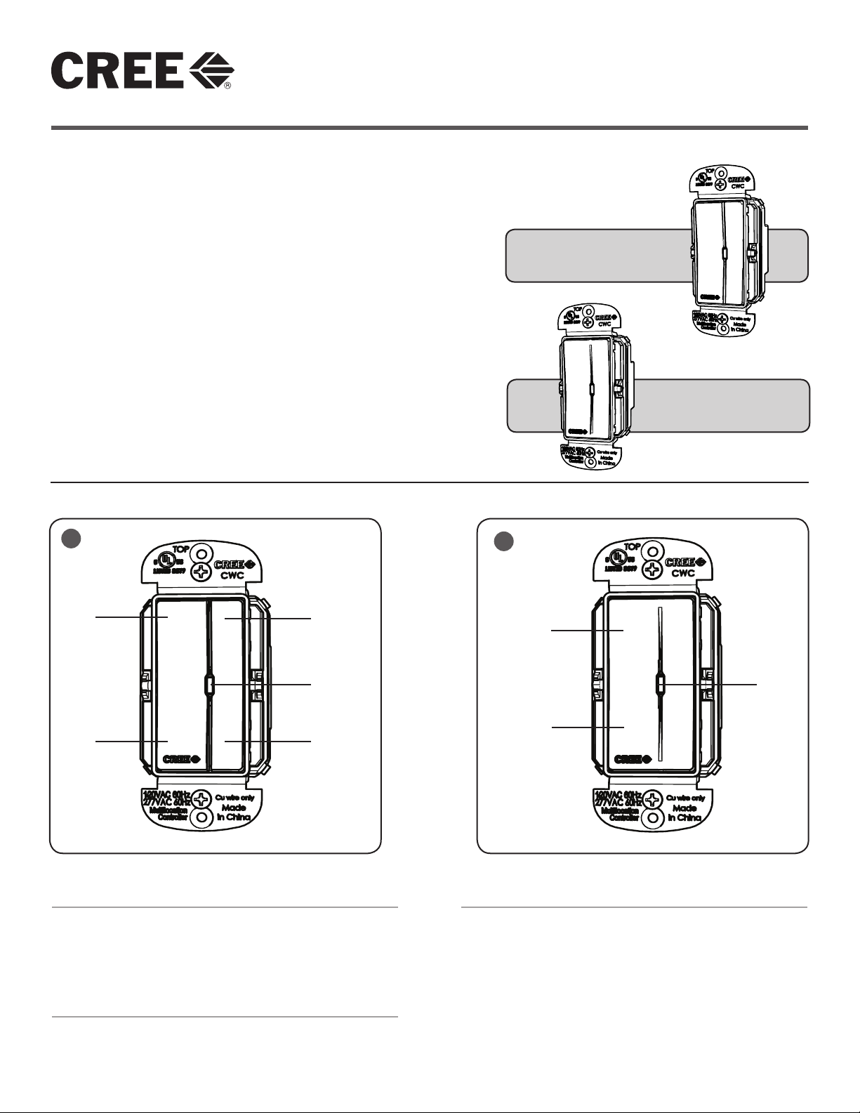
UNIT DESCRIPTION
The Cree Wireless Wall Controls are used with other
SmartCast™ Technology enabled devices to provide wireless
control of LED luminaires. The Cree Wireless Wall Controls
provide on, off, and dimming control options.
2
On
LED
Off
WALL CONTROLS FEATURES
• The Cree Wireless Dimmer supports on, off, and
dimming controls. See Figure 1.
• The Cree Wireless Switch supports on and off, controls.
See Figure 2.
LOAD TYPES
Cree Wall Controls support Cree SmartCast™ Technology
enabled devices only.
1 of 3
LPN000180_H
3
Wall Control LED does not
NEUT
GND
LINE
blink in a 2-blink sequence
prior to OneButton™ Setup
Wall Control will not join a
network
Issue Resolution
Check wiring
(LINE/NEUT/GND required)
Reset Device and verify 2-blink sequence
for the LED
Check wiring (NEUT required)
NOTE: LED may illuminate if NEUT not
connected
Reset Device and verify 2-blink sequence
for the LED
Wall Control Troubleshooting
SUPPLY
LEADS
INSTALLATION
NOTE: For ease of installation, Cree recommends using a deep
wall box.
STEP 1:
Disconnect power to circuit by turning circuit breaker OFF
before installation.
STEP 2:
If necessary remove existing wall plate and switch.
STEP 3:
Strip existing wires ½". If two wires will be connected to the
same terminal on the CWD-CWC or CWS-CWC device, both
wires must be the same gauge (12AWG or 14AWG).
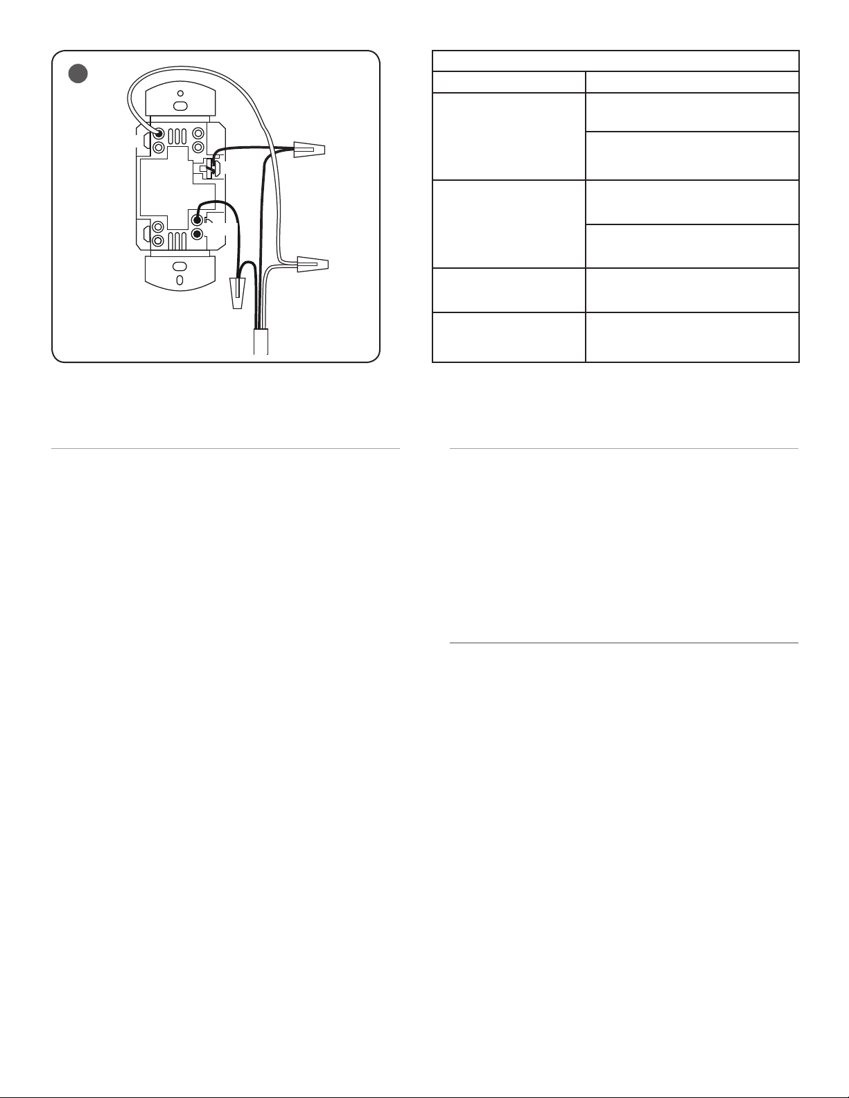
STEP 4:
Wire the LINE (black), NEUTRAL (white), and GND (green or
bare) supply wires to the corresponding pigtail leads on the
CWD-CWC or CWS-CWC, as shown in Figure 3.
NOTE: If replacing an existing wall switch, the wall control shall
be wired as instructed; however, the switched power to the
load must also be tied directly to the AC supply leads.
STEP 5:
Attach the wall plate (reference the wall plate instruction
sheet).
STEP 6:
Switch the circuit breaker ON.
STEP 7:
Press and release the OFF paddle. The blue LED should blink
twice and then go off. If the blue LED does not respond with
the two-blink sequence, please follow the RESET instructions
to return the wall control to factory defaults.
Replaced existing Wall
Control and fixtures will not
turn on
Wall Control will not control
fixtures
Check Wiring (each fixture shall be wired
with constant HOT)
Check group assignments with
Configuration Tool
RESET WALL CONTROLS
STEP 1:
Press/Hold (approx 30 sec) ON paddle until the LED flashes
fast.
STEP 2:
Briefly release the paddle for less than
1 sec (Fast flashing continues)
STEP 3:
Press/Hold ON paddle for 1 sec until fast flashing stops. If
the blue LED does not respond with the two-blink sequence,
please repeat the RESET procedure.
CLEANING
Clean using a cloth dampened only with water and a little mild
detergent. Use of solvents or hydrocarbon-based cleaners may
cause permanent damage.
2 of 3
LPN000180_H
 Loading...