

Ideal Lighting CREE Lighting CIF Users Manual
Wireless 0-10V Dimming/Switching Interface with SmartCast™ Technology
IMPORTANT SAFEGUARDS
When using electrical equipment, basic safety precautions should always be
followed including the following:
READ AND FOLLOW ALL SAFETY INSTRUCTIONS
1. Before installing turn off the power at the circuit breaker.
2. Must be installed in accordance with the national and local building codes and
electrical wiring codes including wiring methods and wiring connections. If you
are not familiar with these codes and requirements, consult a qualied electrician.
3. Indoor use only and suitable for damp locations.
4. Any changes or modications to these devices not explicitly approved by
manufacturer could void your authority to operate this equipment.
SAVE THESE INSTRUCTIONS FOR FUTURE REFERENCE
• Voltage: 120-277V, 60Hz
• Load Type: 120-277VAC 5-2.1A 600W MAX. (Electric Ballast/ General
Purpose (LED))
• Install using a junction box that has a 1/2" knockout
0-10V Interface
Includes: CIF-10V-CWC-SNSR
INSTALLATION INSTRUCTIONS
Blue LED is Inside the Relay Box, Light
will Shine Through at the LED Placement
Shown Below.
Blue LED
Placement
UNIT DESCRIPTION
The Cree Wireless 0-10V Interface is used to
wirelessly control LED luminaires that do not
have built in Cree SmartCast ™ Technology. The
Cree Wireless 0-10V Interface provides on, off,
and 0-10V dimming control.
LOAD TYPES
0-10V dimmable loads (IEC60929)
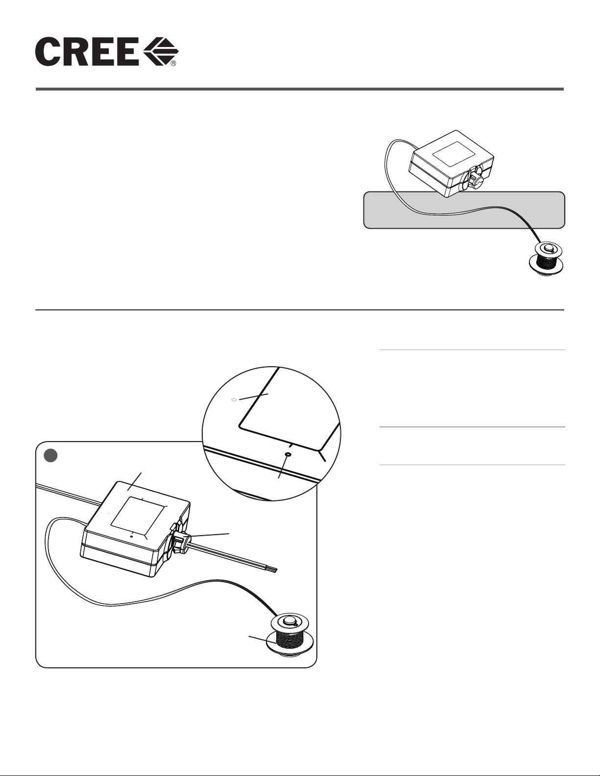
1
Interface Box
Test/Reset
Button Inside
INSTALLATION
NOTE: For ease of installation, Cree
recommends using a Junction Box with a ½"
knockout.
STEP 1:
This End Insert into
Junction Box
Disconnect power to circuit by turning circuit
breaker OFF before installation.
STEP 2:
Remove Junction Box cover.
STEP 3:
Remove knockout and firmly install plastic
relay box into Junction Box until it snaps and is
securely attached
STEP 4:
Strip existing Junction Box wires ½".
Sensor
STEP 5:
Make wiring connection per the Electrical
Connection section.
STEP 6:
Attach Junction Box cover.
STEP 7:
Install sensor into ceiling by drilling a 2" hole
into the ceiling.
1 of 3
LPN00212X0005A3_B
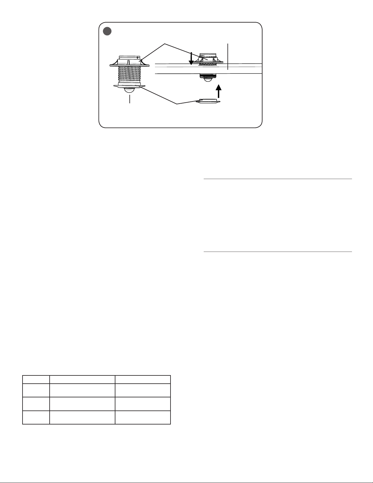
2
Large Trim Ring
Ceiling
Sensor
Small Trim Ring
STEP 8:
Unscrew the small trim ring near the sensor and place sensor
assembly through the ceiling. See Figure 2.
STEP 9:
Secure the sensor assembly by screwing the small trim ring
removed in Step 8 back onto the sensor assembly. Tighten
the larger trim ring above the ceiling until it is snugged tight
against the ceiling. See Figure 2.
STEP 10:
Switch the circuit breaker ON.
STEP 11:
The blue LED should repeat a two blink sequence. If the blue
LED does not respond with the two-blink sequence, please
follow the RESET instructions to return the 0-10V Interface to
factory defaults.
STEP 12:
Verify the LOAD wiring with the following TEST instructions:
• Press and hold the Test/Reset button for 5 sec then
release. The blue LED should respond with a five-blink
sequence. Once test mode has been entered, LOAD
enters State 1. See Figure 1.
• Press and hold Test/Reset button for 1 sec then
release to transition to the next state. The sequence
repeats after State 3. Please refer to the load table
below for your load type.
• To exit test mode at any time, press and hold the Test/
Reset button for 5 sec then release. The five-blink
sequence ends when test mode is exited.
RESET
STEP 1:
Press and hold Test/Reset button until the LED flashes fast
(approximately 30 seconds).
STEP 2:
Release the Test/Reset button for 1 second (Fast flashing
continues). Press and hold Test/Reset for 1 second until fast
flashing stops. If the blue LED does not respond with the
two-blink sequence, please repeat the RESET procedure.
TROUBLESHOOTING:
Out of the box, if the LOAD does not turn on when power is
applied:
Perform TEST mode to verify proper functionality of the load
type
• If TEST mode fails, check Wiring with power off.
• If wired correctly, check to see if Blue LED is blinking.
• If Blue LED is blinking, then perform a RESET (See
RESET section).
• If Blue LED is on solid or off, call Cree Customer
Service.
• If you have done a RESET, and the LOAD is still off,
call Cree Customer Service.
If LOAD is unresponsive use Cree Configuration Tool to verify
configuration.
Dimmable Non-Dimmable
State 1 Off Off
State 2 Max light output (10V) On
State 3 Min light output (1V) On
2 of 3
LPN00212X0005A3_B
 Loading...