

IDEAL INDUSTRIES, INC.
TECHNICAL MANUAL
IDEAL OTDR
Form number: 33-960 Series Revision: September 12, 2008

Copyright © 2008 IDEAL All rights reserved. No part of this publication may
be reproduced, stored in a retrieval system or transmitted in any form, be it
electronically, mechanically, or by any other means such as photocopying,
recording or otherwise, without the prior written permission of IDEAL
(IDEAL).
Information provided by IDEAL is believed to be accurate and reliable.
However, no responsibility is assumed by IDEAL for its use nor for any
infringements of patents or other rights of third parties that may result from
its use. No license is granted by implication or otherwise under any patent
rights of IDEAL.
IDEAL’s Commerce And Government Entities (CAGE) code under the
North Atlantic Treaty Organization (NATO) is 0L8C3.
The information contained in this publication is subject to change without
notice.
Trademarks
IDEAL’s trademarks have been identified as such. However, the presence
or absence of such identification does not affect the legal status of any
trademark.
Units of Measurement
Units of measurement in this publication conform to SI standards and
practices.
Version number: 4.0.1
ii IDEAL

Contents
Contents
Certification Information ....................................................................................................... vi
1 Introducing the IDEAL OTDR ........................................................................ 1
Main Features .........................................................................................................................1
Power Sources ........................................................................................................................5
Typical Applications ................................................................................................................5
OTDR Basic Principles ..............................................................................................................6
Conventions ............................................................................................................................8
2 Safety Information ....................................................................................... 9
Laser Safety Information (Units without VFL) ..........................................................................9
Laser Safety Information (Units with VFL) .............................................................................10
Electrical Safety Information .................................................................................................10
3 Getting Started with Your OTDR ............................................................... 11
Turning the Unit On and Off .................................................................................................11
Using Menus and Keypad .....................................................................................................13
4 Customizing Your OTDR ............................................................................. 15
Selecting the Distance Units .................................................................................................15
Selecting the Language of Operation ...................................................................................16
Setting the Date and Time ....................................................................................................17
Adjusting the Brightness .......................................................................................................18
Selecting a Printer .................................................................................................................19
Configuring the Power Management Settings ......................................................................20
5 Setting Up Your OTDR ................................................................................ 21
Installing the Universal Interface (UI) ....................................................................................21
Cleaning and Connecting Optical Fibers ...............................................................................22
Setting General OTDR Parameters .........................................................................................23
Setting the Acquisition Parameters .......................................................................................25
Setting Analysis Parameters ..................................................................................................28
Setting Pass/Fail Thresholds ..................................................................................................30
Setting Macrobend Parameters .............................................................................................32
Setting Storage Parameters ..................................................................................................34
OTDR iii

Contents
6 Testing Fibers ..............................................................................................37
Testing in Auto Mode ...........................................................................................................38
Testing in Fault Finder Mode .................................................................................................41
Testing in Manual (Advanced) Mode .....................................................................................43
Monitoring Fiber in Real Time Mode .....................................................................................46
Launch Conditions for Multimode Measurements ................................................................49
7 Managing Test Results ................................................................................51
Summary Pane ......................................................................................................................51
Events Pane ..........................................................................................................................52
Trace Pane .............................................................................................................................53
Trace Info. Pane ....................................................................................................................54
Using Markers .......................................................................................................................56
Using Zoom Controls ............................................................................................................57
Printing Test Results ..............................................................................................................59
Opening Trace Files ...............................................................................................................60
Saving Files ...........................................................................................................................61
Checking Available Memory ..................................................................................................63
Creating Folders ....................................................................................................................63
Copying, Renaming, or Deleting Files and Folders ................................................................64
Transferring Results to a Computer .......................................................................................66
8 Using Your OTDR as a Light Source ............................................................71
Activating/Deactivating a Light Source .................................................................................72
Modulating the Source Signal ..............................................................................................73
9 Maintenance ................................................................................................75
Cleaning UI Connectors ........................................................................................................76
Recharging Main Batteries ....................................................................................................78
Replacing Batteries ...............................................................................................................79
Recalibrating the Unit ...........................................................................................................80
Upgrading the IDEAL OTDR Software ...................................................................................81
Recycling and Disposal (Applies to European Union Only) ....................................................83
10 Troubleshooting ..........................................................................................85
Solving Common Problems ...................................................................................................85
Obtaining Online Help ..........................................................................................................88
Customer Support and Technical Assistance .........................................................................89
Transportation ......................................................................................................................91
iv IDEAL

Contents
11 Warranty ..................................................................................................... 93
General Information .............................................................................................................93
Liability .................................................................................................................................93
Exclusions .............................................................................................................................94
Service and Repairs ...............................................................................................................95
IDEAL Service Centers Worldwide .........................................................................................96
A Description of Event Types ........................................................................ 97
Span Start ............................................................................................................................97
Span End .............................................................................................................................97
Continuous Fiber .................................................................................................................98
End of Analysis ....................................................................................................................99
Non-Reflective Event ..........................................................................................................100
Positive Event .....................................................................................................................101
Launch Level ......................................................................................................................102
Fiber Section ......................................................................................................................103
Reflective Event (Possible Echo) .........................................................................................104
Echo ..................................................................................................................................105
Merged Reflective Event ....................................................................................................106
Reflective Event .................................................................................................................108
Index .............................................................................................................. 109
OTDR v

Certification Information
Certification Information
F.C.C. Information
Electronic test equipment is exempt from Part 15 compliance (FCC) in
the United States. However, compliance verification tests are
systematically performed on most IDEAL equipment.
Information
Electronic test equipment is subject to the EMC Directive in the European
Union. The EN61326 standard prescribes both emission and immunity
requirements for laboratory, measurement, and control equipment.
This unit has undergone extensive testing according to the European Union
Directive and Standards.
vi IDEAL

Certification Information
DECLARATI ON OF CONFORM ANCE
Ideal Industries Limited
Unit 3, Europa Court
Europa Boulevard
Westbrook
Warrington
Cheshire
WA5 7TN
United Kingdom
Declare that the following product(s):
IDEAL 33-960 Series handheld OTDR with all accessories
to which this declaration relates are in conformity with the following standard(s) or other
normative document(s):
EN 55022:1998/A2:2003 Limits and Methods of Measurement of Radio
EN 60825-1:1994/A2:2001 Safety of laser products – Part 1: Equipment
EN 61326:1997/A3:2003 Electrical Equipment for Measurement, Control
Disturbance Characteristics of Information
Technology Equipment
classifications, requirements, and user´s guide
and Laboratory Use – EMC Requirements
following the provisions of the following European Community Directives:
89/336/EEC Electromagnetic Compatibility and 72/23/EEC Low Voltage Safety.
Issued on 1st of July, 2008
For and on behalf of Ideal Industries at the above address
Tony Kumeta,
European General Manager
Ideal Industries Limited
Unit 3, Europa Court
Europa Boulevard
Westbrook
Warrington
Cheshire
WA5 7TN
United Kingdom
www.europe.idealindustries.de
OTDR vii

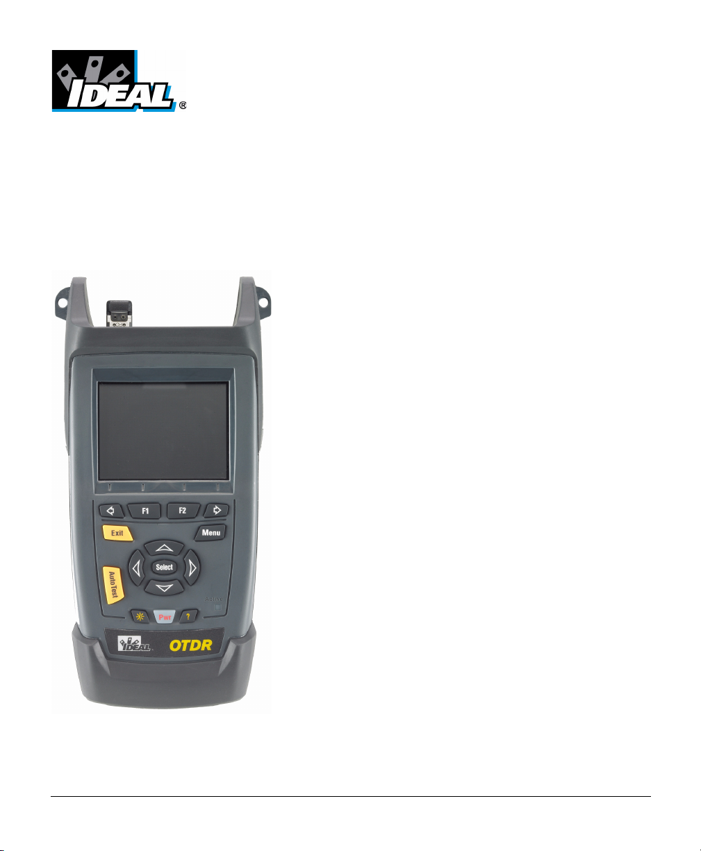
1 Introducing the IDEAL OTDR
The IDEAL OTDR is a compact handheld OTDR optimized for access/FTTx
network testing. The unit can be equipped with optional power meter,
visual fault locator (VFL), and fiber inspection probe.
Main Features
³ Test can be started by pressing a single key
³ Possible to test with acquisition duration as short as 5 seconds
³ One or two OTDR ports (singlemode, multimode, or filtered
wavelength)
³ Screen optimized for outdoor use
³ USB ports (host and client)
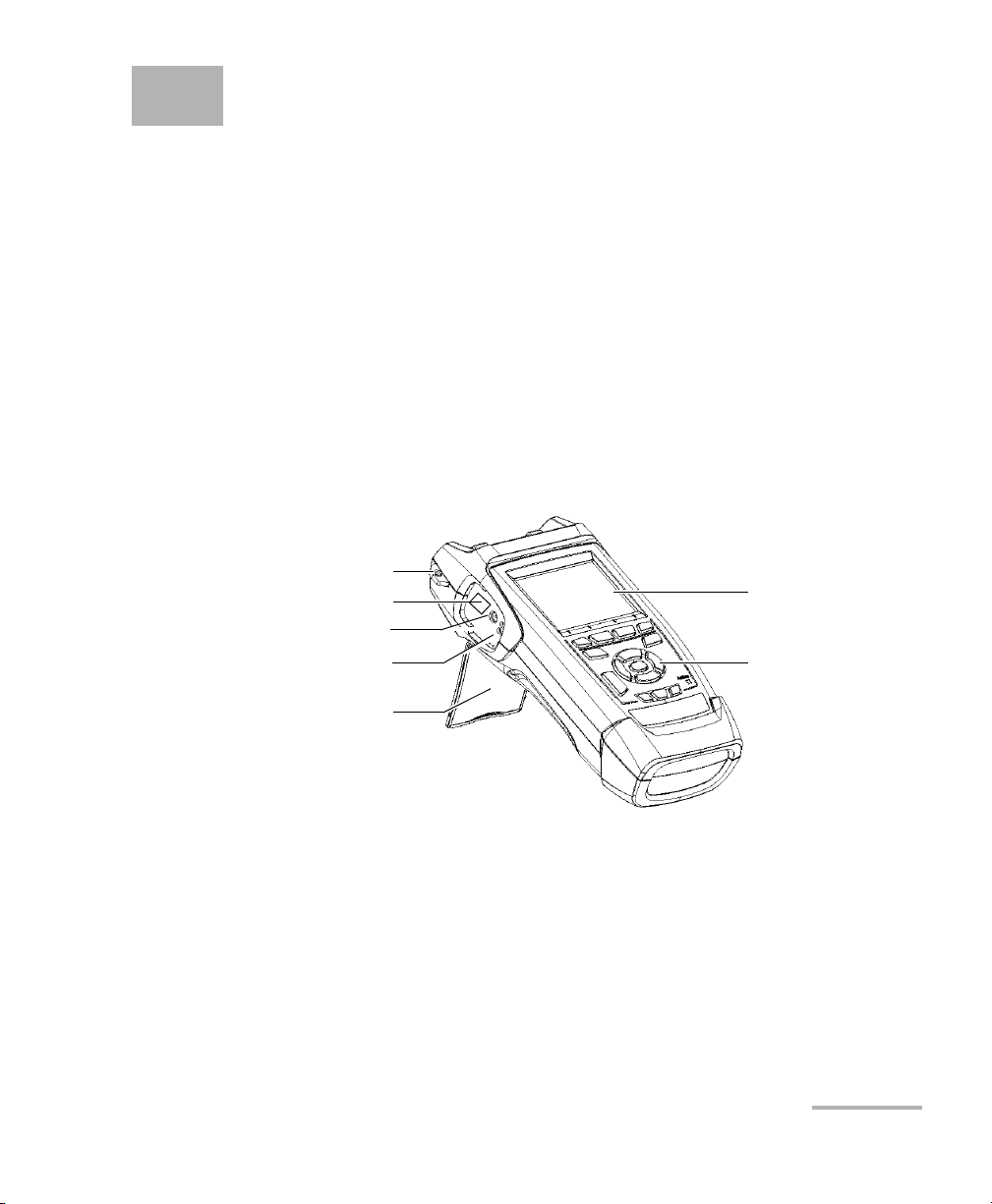
Shoulder strap eyelet
RJ-45 connector
AC adapter/charger connector
Battery charge
status LEDs (one per battery)
Stand
OTDR 1
Display
Keypad
Introducing the IDEAL OTDR
Main Features
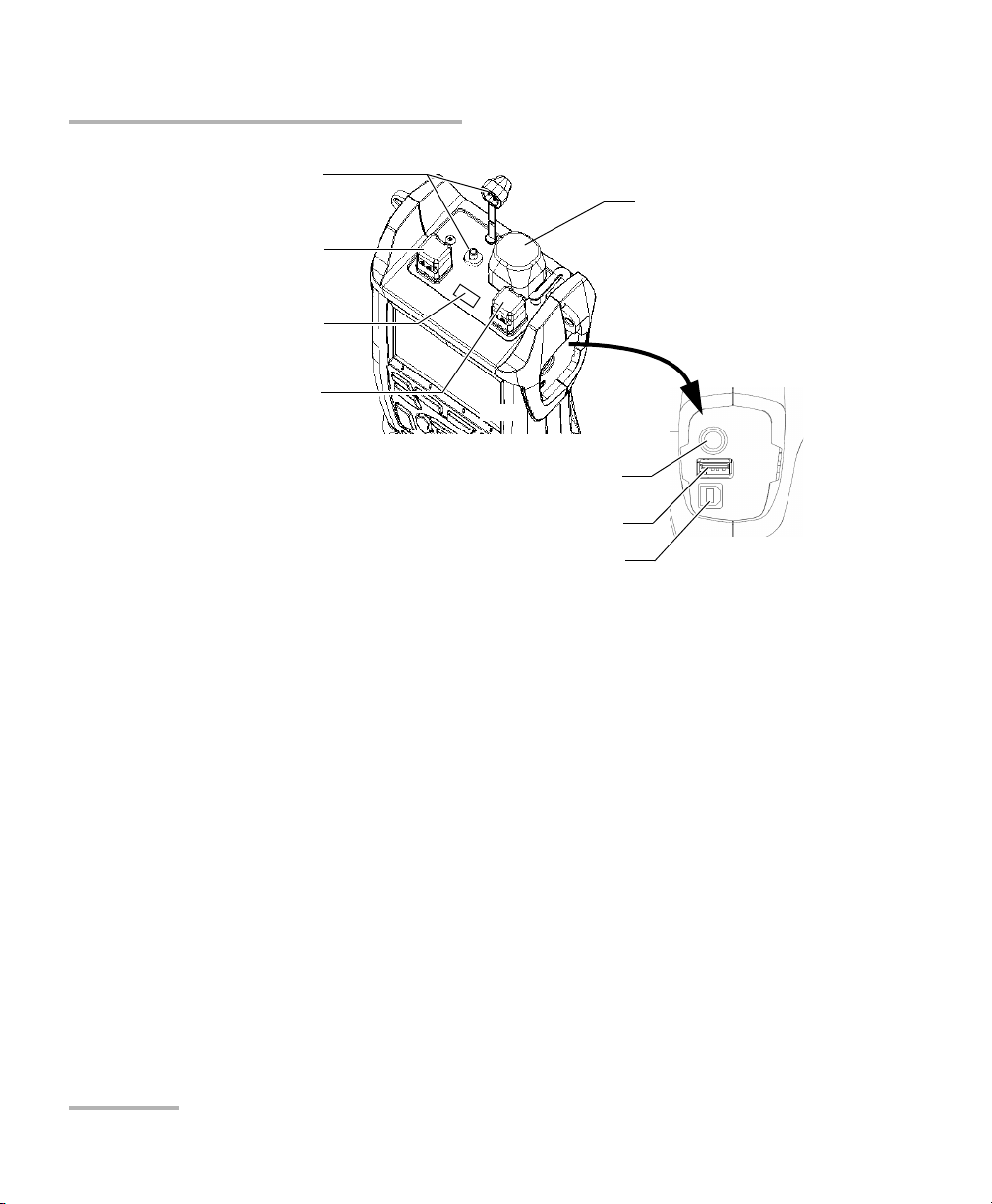
Visual fault locator port
and soft cap (optional)
Singlemode OTDR port
Infrared port (for printer)
On some models only:
Singlemode OTDR port for
in-service testing
OR
Multimode OTDR port
Power meter detector port
(optional)
Inspection probe
connector
USB host port
(for data transfer using memory drive)
USB client port
(for data transfer via ActiveSync)
Note: Ports and connectors on your unit may differ from the illustration.
2 IDEAL
Introducing the IDEAL OTDR
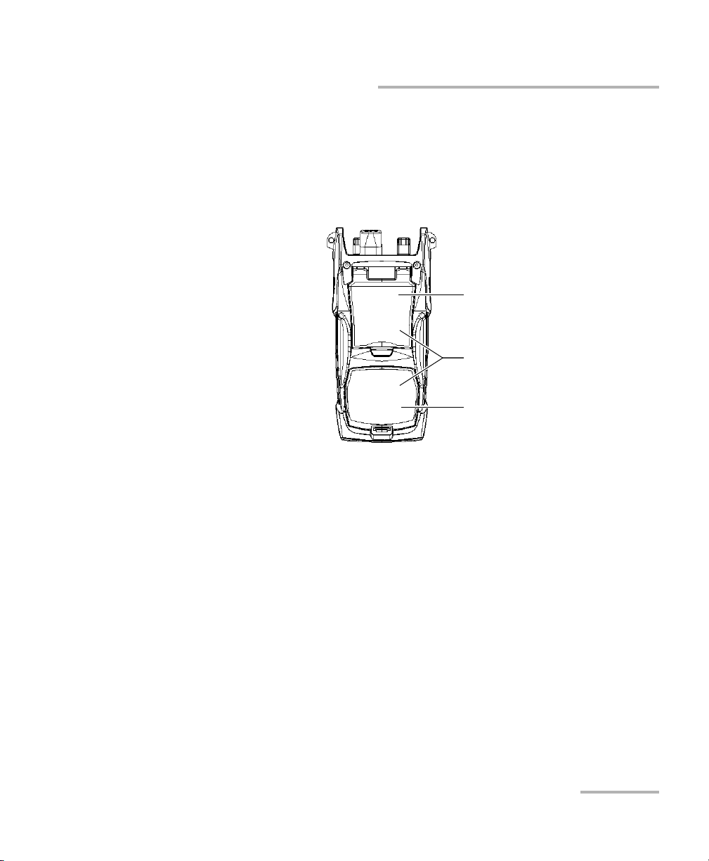
Other test utilities:
³ Visual fault locator to inspect or identify fibers (optional)
³ Video fiber inspection probe (optional)
³ Power meter (optional)
Safety label and serial number
(under the stand)
Quick reference labels
Battery compartment
(two rechargeable batteries)
Main Features
OTDR 3

Introducing the IDEAL OTDR
Main Features
Other useful characteristics:
³ Customizable test thresholds with visual pass/fail analysis
³ Memory for 500 OTDR traces and possible data transfer to a computer
³ Energy-saving features: automatic backlight or unit shutdown
³ Multilingual graphical user interface
³ Comprehensive online help available from each function and Quick
Reference labels affixed to back of unit
³ Data post-processing: You can install the OTDR Viewer software
(provided on the installation CD) on a computer to view and analyze
OTDR traces. You can access more features such as:
³ customized printout
³ batch printing
³ conversion of traces to many formats such as Telcordia or ASCII.
4 IDEAL

Introducing the IDEAL OTDR
Power Sources
Power Sources
The unit operates with the following power sources:
³ AC adapter/charger (connected to standard power outlet—indoor use
only). Compatible car outlet adapter available upon request.
³ Two lithium-ion rechargeable batteries (automatically take over if you
disconnect the AC adapter/charger). Battery recharge is automatic
when the AC adapter/charger is connected.
Typical Applications
You can use the OTDR for several applications, such as:
³ Short-link testing
³ Service activation
³ Fault finder
³ Troubleshooting (dark and live fibers)
OTDR 5

Introducing the IDEAL OTDR
OTDR Basic Principles
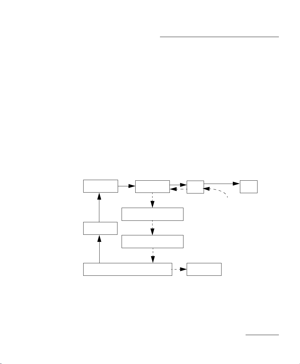
OTDR Basic Principles
An OTDR sends short pulses of light into a fiber. Light scattering occurs in
the fiber due to discontinuities such as connectors, splices, bends, and
faults. An OTDR then detects and analyzes the backscattered signals. The
signal strength is measured for specific intervals of time and is used to
characterize events.
The OTDR calculates distances as follows:
where
c = speed of light in a vacuum (2.998 x 10
t = time delay from the launch of the pulse to the reception of the
pulse
n = index of refraction of the fiber under test (as specified by the
manufacturer)
Distance
Distance
c
t
-- -
-- -
×=
n
2
8
m/s)
6 IDEAL
Introducing the IDEAL OTDR
OTDR Basic Principles
An OTDR uses the effects of Rayleigh scattering and Fresnel reflection to
measure the fiber condition, but the Fresnel reflection is tens of thousands
of times greater in power level than the backscatter.
³ Rayleigh scattering occurs when a pulse travels down the fiber and
small variations in the material, such as variations and discontinuities
in the index of refraction, cause light to be scattered in all directions.
However, the phenomenon of small amounts of light being reflected
directly back toward the transmitter is called backscattering.
³ Fresnel reflections occur when the light traveling down the fiber
encounters abrupt changes in material density that may occur at
connections or breaks where an air gap exists. A very large quantity of
light is reflected, as compared with the Rayleigh scattering. The
strength of the reflection depends on the degree of change in the index
of refraction.
generator
Set of
instructions
Laser
diode
Pulse
Light pulses
Optical
coupler
Returned signal
Avalanche
photodetector (APD)
Analog-to-digital
converter (A/D)
Analyzed signal
Microprocessor
Light pulses
OTDR
port
Reflections coming
Display
Fiber
back to the OTDR
When the full trace is displayed, each point represents an average of many
sampling points. You will have to zoom to see each point (see Using Zoom
Controls on page 57).
OTDR 7

Introducing the IDEAL OTDR
Conventions
Conventions
Before using the product described in this manual, you should understand
the following conventions:
Indicates a potentially hazardous situation which, if not avoided,
could result in death or serious injury. Do not proceed unless you
understand and meet the required conditions.
Indicates a potentially hazardous situation which, if not avoided,
may result in minor or moderate injury. Do not proceed unless you
understand and meet the required conditions.
Indicates a potentially hazardous situation which, if not avoided,
may result in component damage. Do not proceed unless you
understand and meet the required conditions.
WARNING
CAUTION
CAUTION
IMPORTANT
Refers to information about this product you should not overlook.
8 IDEAL

2 Safety Information
WARNING
Do not install or terminate fibers while a light source is active.
Never look directly into a live fiber and ensure that your eyes are
protected at all times.
WARNING
Use of controls, adjustments and procedures for operation and
maintenance other than those specified herein may result in
hazardous radiation exposure or impair the protection provided by
this unit.
Laser Safety Information (Units without VFL)
Your instrument is a Class 1M laser product in compliance with standards
IEC 60825-1 Amendment 2: 2001 and 21 CFR 1040.10. Invisible laser
radiation may be encountered at the output port.
The product is safe under reasonably foreseeable conditions of operation
but it may be hazardous if you use optics within a diverging or collimated
beam. Do not view directly with optical instruments.
Affixed to back
(under the stand)
OTDR 9

Safety Information
Laser Safety Information (Units with VFL)
Laser Safety Information (Units with VFL)
Your instrument is a Class 3R laser product in compliance with standards
IEC 60825-1 Amendment 2: 2001 and 21 CFR 1040.10. It is potentially
harmful in direct intrabeam viewing.
The following label(s) indicate that the product contains a Class 3R source:
Affixed to back
(under the stand)
Indicated on
connector panel
Electrical Safety Information
The AC adapter/charger provided with this unit (14.4 W/9 V) is specifically
designed to work with your IDEAL OTDR.
WARNING
Use the AC adapter/charger indoors only.
Any other AC adapter/charger or power source
(for example, car outlet) must output at least 12 W.
10 IDEAL

3 Getting Started with Your
OTDR
Turning the Unit On and Off
When you turn the unit on, you may use it immediately under normal
conditions.
When the unit is turned off, it keeps the following parameters in its internal
memory:
³ Test parameters
³ User-defined thresholds
³ Regional, LCD, and energy-saving settings
³ Saved test results
IMPORTANT
If you remove batteries (and the AC adapter/charger is
disconnected), the unit will turn off without saving the above
elements.
OTDR 11

Getting Started with Your OTDR
Turning the Unit On and Off
There are two ways to turn off the IDEAL OTDR
³ Suspend: the next time you turn your unit on, you will quickly return to
your work environment.
³ Shutdown: completely cuts power to the unit; the unit will perform a
complete restart routine the next time you use it. You should perform a
shutdown if you do not intend to use your unit for a week or more.
To turn the unit on:
Press Pwr. The unit initializes for a few seconds and displays the OTDR
Parameters pane.
To enter the suspend mode:
Hold down the Pwr key for about two seconds. Release the key as soon as
you hear a beep.
To perform a shutdown:
Hold down the Pwr key for about five seconds. You will hear a first beep;
release the key after you hear a second beep.
12 IDEAL
Getting Started with Your OTDR
Using Menus and Keypad
Using Menus and Keypad
You can access optical tools from the keypad or menu. Menu options may
differ depending on your unit configuration.
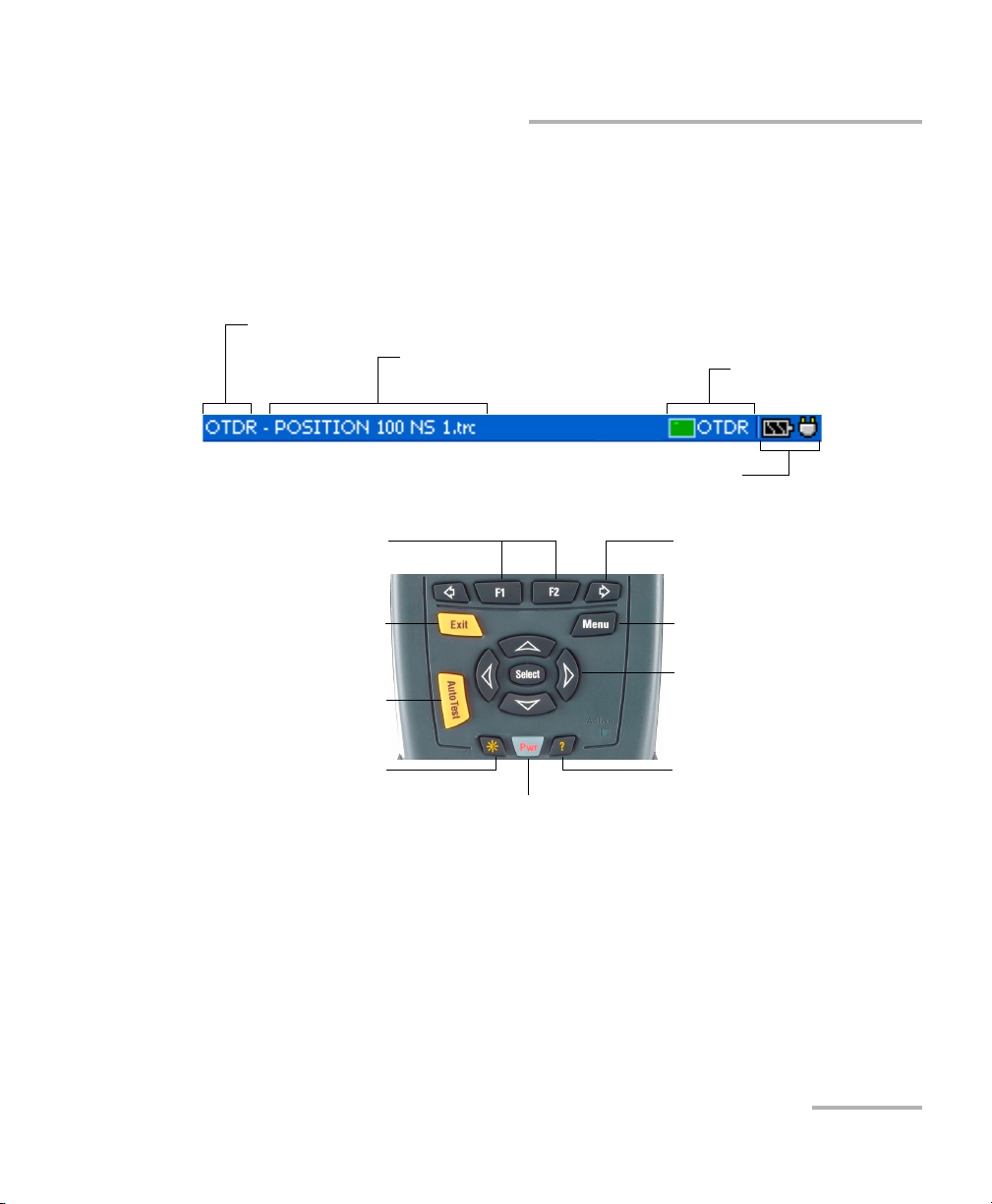
Status Bar
Utility name (OTDR, File Manager, etc.)
Trace name OTDR status
(active/not active)
Battery status and AC adapter/charger status
Keypad
To activate the function
displayed directly above
To scroll through available
functions
To cancel/exit current function
To start (or stop) an acquisition
To adjust brightness (four levels)
To turn unit on/off
To access the main menu
To move around, select items,
and change parameters
To access help about
current function
To access main features:
1. Press the Menu key.
2. Use the arrows to select a feature and press Select.
OTDR 13

Getting Started with Your OTDR
Using Menus and Keypad
To activate F1/F2 functions:
1. Use the left/right function arrows (on each side of the F1/F2 keys) to
display the desired function or parameter.
2. Press the F1 or F2 key located just below.
To access and modify on-screen parameters:
1. Use the arrows to select an on-screen item (list, check box, etc.).
2. Press Select to activate or open it.
To enter text or numbers with an on-screen keyboard:
³ Use the left/right function arrows (on each side of the F1/F2 keys) to
move the cursor in the text.
³ Use the up/down and left/right arrows to select a character, and then
press Select to add it.
³ Press OK (F1 key) to accept the element, and then hide the keyboard.
14 IDEAL
4 Customizing Your OTDR
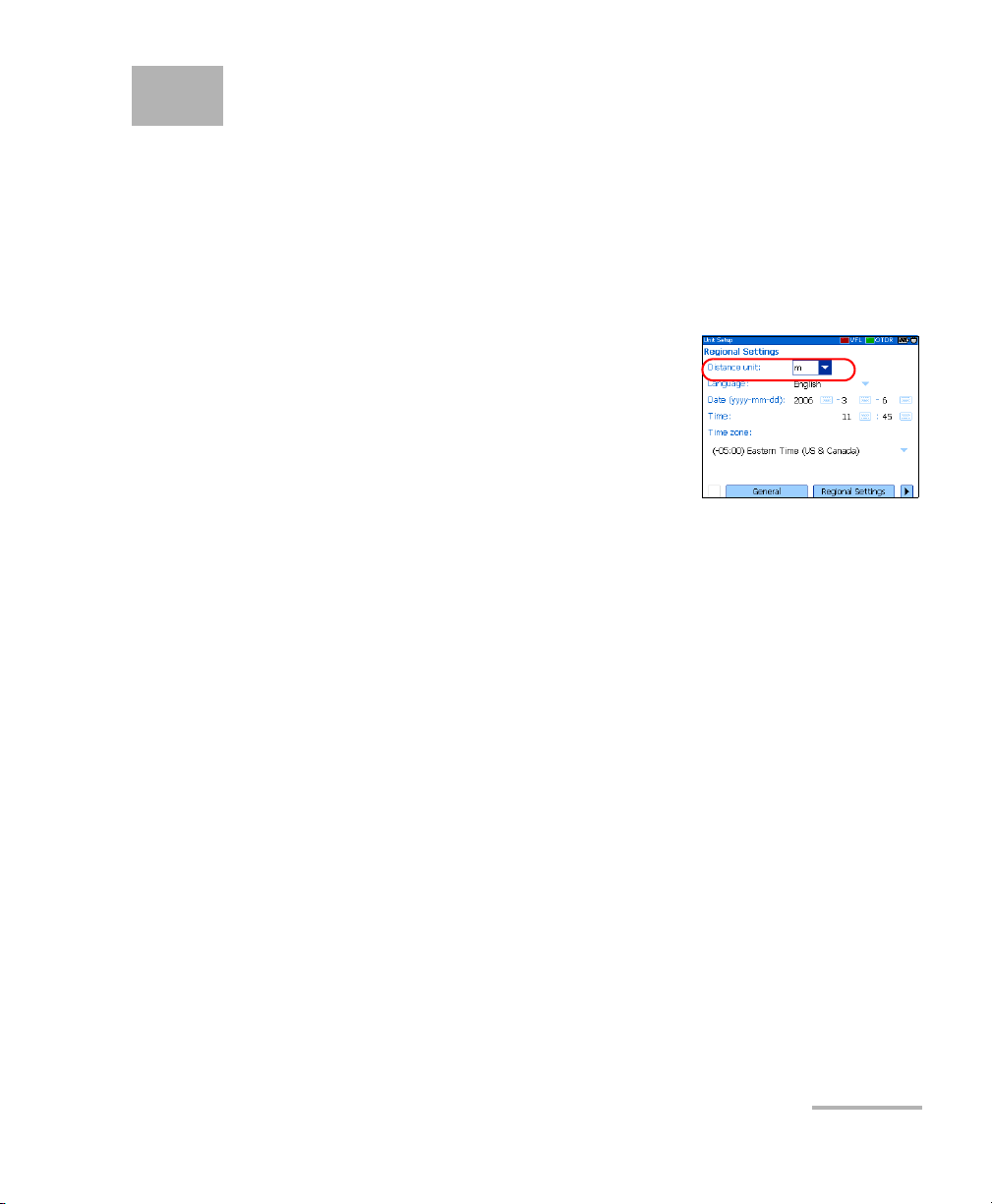
Selecting the Distance Units
There are three distance units available: meters, miles, and kilofeet.
Note: The attenuation values are always expressed in dBs per kilometer.
To select distance units:
1. Press Menu, select Setup > Unit, and then
press Select.
2. Use the left/right function arrows until you
see Regional Settings, and then press F2 to
display the pane.
3. Press Select to open the Distance unit list.
4. With the current distance unit highlighted, use the up/down arrows to
select the desired unit, and then press Select to activate it.
OTDR 15
Customizing Your OTDR
Selecting the Language of Operation
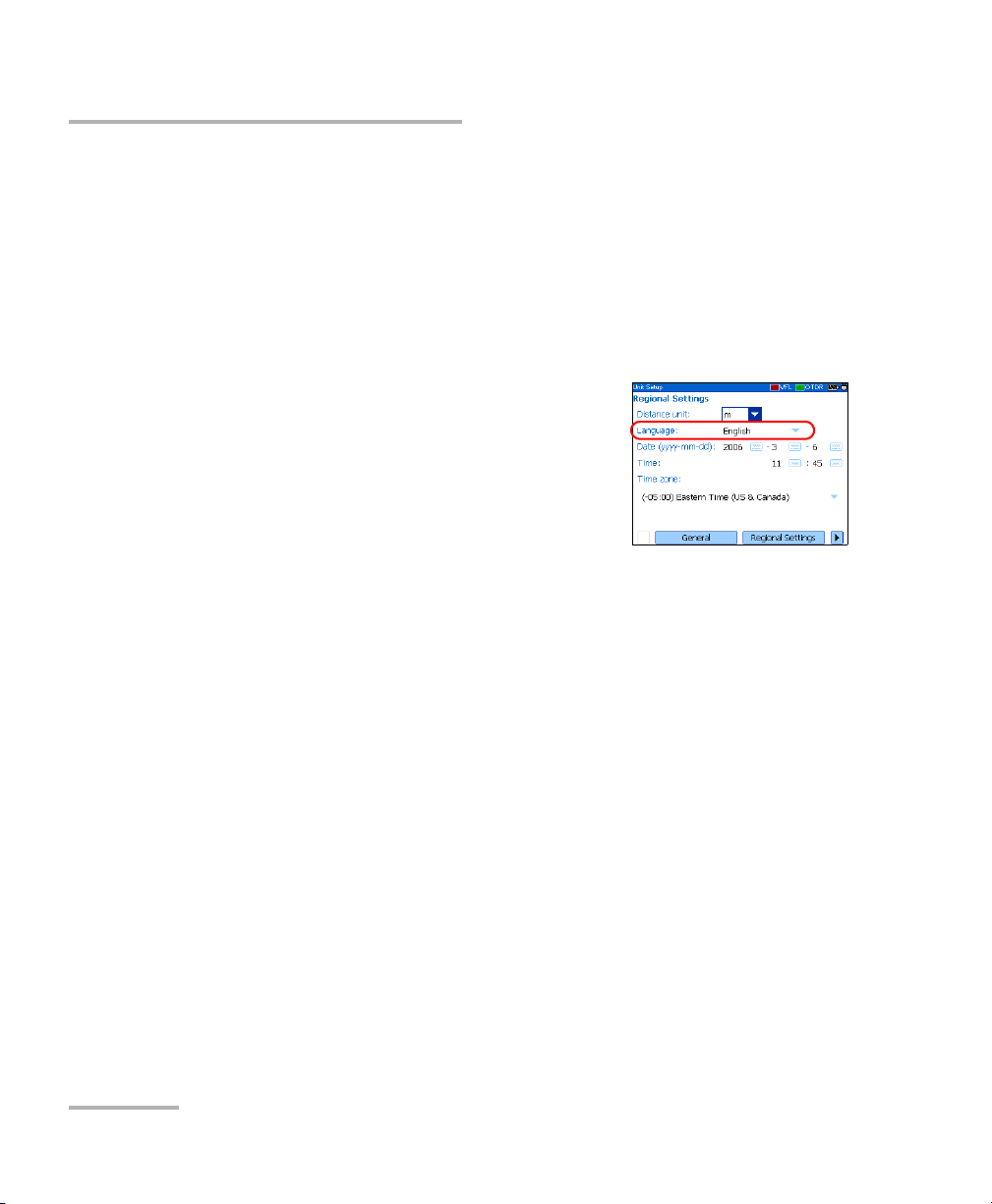
Selecting the Language of Operation
You may display the user interface in one of the available languages
(default is English). If other languages become available in the future, you
could access them by replacing the unit software (see Upgrading the
IDEAL OTDR Software on page 94). Values are kept in memory when you
turn the unit off.
To select a new interface language:
1. Press Menu, select Setup > Unit, and then
press Select.
2. Use the left/right function arrows until you
see Regional Settings, and then display the
pane (F1/F2 key).
3. Use the up/down arrows to select the
Language list, and then press Select to open it.
4. With the current language highlighted, use the up/down arrows to
select the desired language, and then press Select to activate it.
Once you have modified the language, you will be prompted to restart
your unit.
16 IDEAL
Customizing Your OTDR
Setting the Date and Time
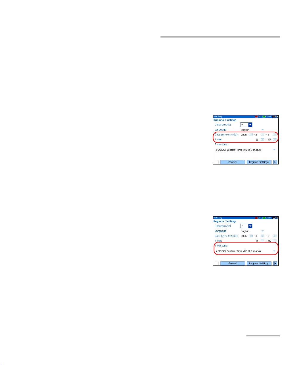
Setting the Date and Time
When saving results, the unit also saves the corresponding date and time.
You must enter the date according to the year-month-day format and the
time according to the 24-hour format.
You can also modify the time zone.
To set the date and time:
1. Press Menu, select Setup > Unit, and then
press Select.
2. Use the left/right function arrows until you
see Regional Settings, and then display the
pane (F1/F2 key).
3. Use the arrows to select any of the date or
time settings, and then press Select to display the on-screen keyboard
(for details about using keyboards, see Using Menus and Keypad on
page 13).
4. Enter the new value and press OK (F1/F2 key).
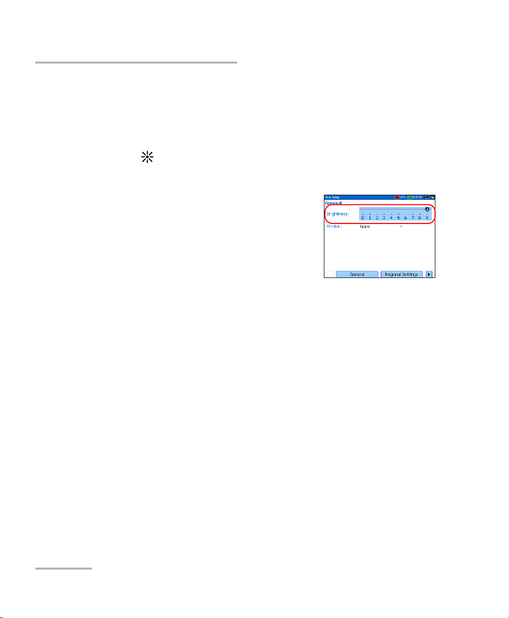
To modify the time zone:
1. Press Menu, select Setup > Unit, and then
press Select.
2. Use the left/right function arrows until you
see Regional Settings, and then display the
pane (F1/F2 key).
3. Use the arrows to select the Time zone list,
and then press Select to open it.
4. With the current time zone highlighted, use the up/down arrows to
select the desired time zone, and then press Select to activate it.
OTDR 17
Customizing Your OTDR
Adjusting the Brightness
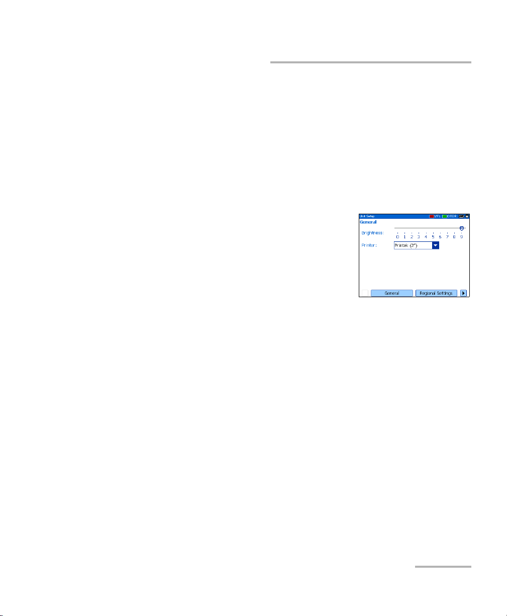
Adjusting the Brightness
To fit your work environment, you may adjust the LCD brightness. Values
are kept in memory when you turn the unit off.
To adjust the display brightness:
Press the key repeatedly to switch between brightness levels (0-3-6-9).
OR
1. Press Menu, select Setup > Unit, and then
press Select.
2. If necessary, use the left/right function
arrows until you see General, and then
display the pane (F1/F2 key).
By default, the Brightness slider is selected.
3. Use the left/right arrows to adjust the brightness level.
18 IDEAL
Customizing Your OTDR
Selecting a Printer
Selecting a Printer
To print reports, you must configure the printer first. Your unit supports the
Printek 2” printer only and communicates with it via the infrared port
located on the top panel.
If you want to print on a network printer or if you want to print other type of
reports, you must transfer the desired files on a computer on which
OTDR Viewer is installed.
To select a printer:
1. Press Menu, select Setup > Unit, and then
press Select.
2. If necessary, use the left/right function
arrows until you see General, and then
display the pane (F1/F2 key).
3. Use the up/down arrows to select the Printer
list, and then press Select to open it.
4. With the current printer highlighted, use the up/down arrows to select
the desired printer, and then press Select to activate it.
OTDR 19
Customizing Your OTDR
Configuring the Power Management Settings
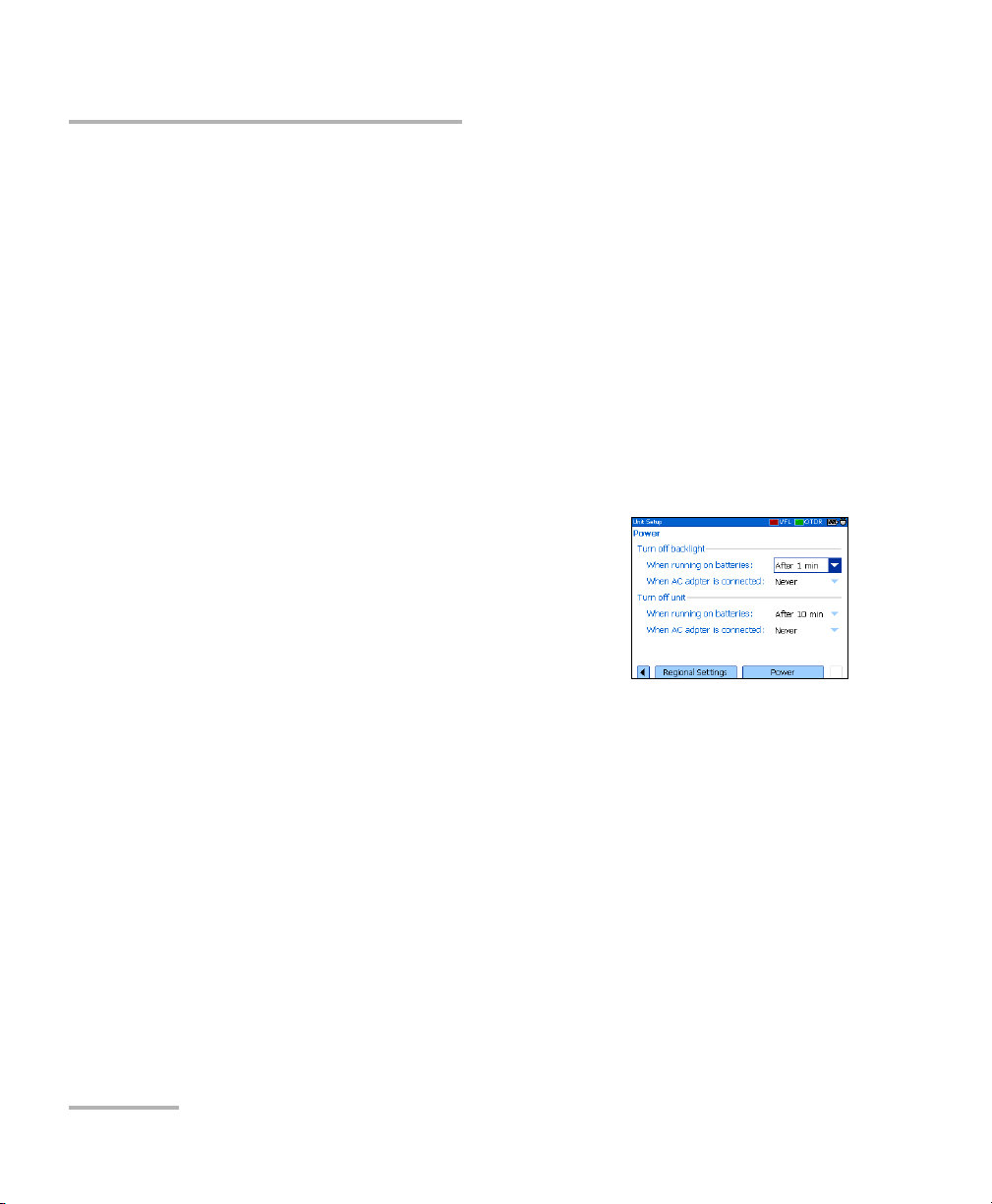
Configuring the Power Management Settings
When you do not use the unit for a while, the display may be dimmed to
save power.
You can set idle durations for AC adapter/charger and battery operation.
The unit goes in suspend mode after the specified duration has expired
(see Turning the Unit On and Off on page 11).
Values are kept in memory when you turn the unit off.
Note: When the backlight is dimmed, the unit operation is not interrupted. Press
any key to return to normal operation.
To configure the power management settings:
1. Press Menu, select Setup > Unit, and then
press Select.
2. Use the left/right function arrows until you
see Power, and then display the pane
(F1/F2 key).
3. Use the up/down arrows to go to the Tu rn
off backlight or Turn off unit section.
4. Use the up/down arrows to select the battery or AC adapter/charger
duration list, and then press Select to open the list.
5. With the current duration highlighted, use the up/down arrows to
select the desired duration (or Never), and then press Select to
confirm.
20 IDEAL
5 Setting Up Your OTDR
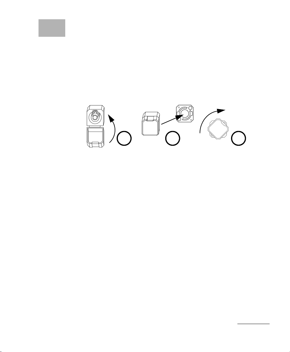
Installing the Universal Interface (UI)
The UI fixed baseplate is available for connectors with angled (APC) or
non-angled (UPC) polishing.
To install a UI connector adapter onto the UI baseplate:
1. Hold the UI connector adapter so the dust cap opens downwards.
2 3 4
2. Close the dust cap in order to hold the connector adapter more firmly.
3. Align keys and insert the connector adapter into the baseplate.
4. While pushing firmly, turn the connector adapter clockwise on the
baseplate to lock it in place.
OTDR 21

Setting Up Your OTDR
Cleaning and Connecting Optical Fibers
Cleaning and Connecting Optical Fibers
To ensure maximum power and to avoid erroneous readings:
³ Always clean fiber ends as explained below before inserting
them into the port. IDEAL is not responsible for damage or
errors caused by bad fiber cleaning or handling.
³ Ensure that your patchcord has appropriate connectors. Joining
mismatched connectors will damage the ferrules.
To connect the fiber-optic cable to the port:
1. Carefully align the connector and port to prevent the fiber end from
touching the outside of the port or rubbing against other surfaces.
If your connector features a key, ensure that it is fully fitted into the
port’s corresponding notch.
2. Push the connector in so that the fiber-optic cable is firmly in place,
thus ensuring adequate contact.
IMPORTANT
If your connector features a screwsleeve, tighten the connector
enough to firmly maintain the fiber in place. Do not overtighten, as this
will damage the fiber and the port.
Note: If your fiber-optic cable is not properly aligned and/or connected, you will
notice heavy loss and reflection.
22 IDEAL

Setting General OTDR Parameters
Setting General OTDR Parameters
You can set preferences such as:
³ Grid: You can display or hide the grid appearing on the graph’s
background. By default, the grid is displayed.
³ Zoom and markers: You can display or hide the zoom controls as well
as the markers appearing on the graph.
³ Automatic zoom on fiber span: You can set the trace display to show
only the portion of the trace that is located between the span start and
the span end, in full-trace view. By default, this feature is selected.
Even if the application automatically zooms in on the fiber span, you
can adjust the zoom manually. You can even zoom in on events
located outside the fiber span. For more information on how to use the
zoom controls, see Using Zoom Controls on page 57.
³ Reference file: You can enable or disable the selection of a reference
trace. A reference trace is used to compare fibers of a same cable,
monitor fiber deterioration, or compare fibers before and after
installation. This trace appears in red on the graph.
³ Summary pane (available only with the optional FTTx software
package): By default, the Summary pane is automatically displayed as
soon as an acquisition is complete. You can disable this automatic
display (you can always access it via the Summary button from the
OTDR pane.)
³ Event (fiber) sections: You can display or hide event (fiber) sections in
the Events pane, depending on the types of values you want to view. If
you display event sections, the Events pane will include section length
and section attenuation.
For example, by hiding the event (fiber) sections, you can obtain the
running total of connector and splice losses instead of having a loss
value for the entire link. Information on event sections is also available
from the Trace pane, in the events table located just below the graph.
OTDR 23

Setting General OTDR Parameters
To set the general OTDR parameters:
1. Press Menu, select Setup > OTDR, and then
press Select.
2. Display the General pane (F1/F2 key).
3. Use the up/down arrows to highlight the
desired item, and then press Select to
select it.
You can press Select one more time to clear the boxes.
To revert to the factory-default settings:
1. Press Menu, select Setup > OTDR, and then press Select.
2. From the General pane, use the arrows to select Default, and then
press Select to confirm.
24 IDEAL

Setting the Acquisition Parameters
Setting the Acquisition Parameters
You can set parameters such as IOR (group index), backscatter, and helix
factor. You can also enable or disable the first connector check.
Setting the IOR, Backscatter, and Helix Factor
Your unit contains default IOR (group index), backscatter, and helix factor
values that you can modify if they do not suit your testing needs. You
should set the IOR (group index), backscatter, and helix factor before
performing tests in order to apply them to all newly acquired traces.
³ The index of refraction (IOR) (also known as group index) is used to
convert time-of-flight to distance. Having the proper IOR is crucial for
all OTDR measurements associated with distance (event position,
attenuation, total length, etc.). IOR is provided by the cable or fiber
manufacturer.
³ The (Rayleigh) backscatter value represents the amount of backscatter
in a particular fiber. The backscatter is used in the calculation of ORL
and reflectance, and it can usually be obtained from the cable
manufacturer.
³ The helix factor takes into account the difference between the length
of the cable and the length of the fiber inside the cable; it does not vary
with wavelengths.
The length of the OTDR distance axis is always equivalent to the
physical length of the cable (not the fiber).
OTDR 25

Setting the Acquisition Parameters
To set the IOR, backscatter, and helix factor parameters:
1. Press Menu, select Setup > OTDR, and then press Select.
2. Display the Acquisition pane (F1/F2 key).
3. Use the up/down arrows to select the wavelength box, and then press
Select to open it.
4. Select the wavelength for which you want to modify parameters. Press
Select to confirm your choice.
5. Use the arrows to select any of the settings, and then press Select to
display the on-screen keyboard (for details about using keyboards, see
Using Menus and Keypad on page 13).
Do not change the default backscatter parameter unless you have
values provided by the fiber manufacturer. If you set this parameter
incorrectly, your reflectance measurements will be inaccurate.
6. Enter the new value and press OK (F1/F2 key).
IMPORTANT
As you enter the value, the application indicates the minimum or
maximum value allowed.
26 IDEAL

Setting the Acquisition Parameters
Enabling or Disabling the First Connector Check
The first connector check feature is used to verify that the fibers are
properly connected to the OTDR. It verifies the injection level and the
reflectance of the first connector. It displays a message when a unusually
high loss or reflectance occur at the first connection.
You enable or disable this feature for all wavelengths at a time.
To enable or disable the first connector check:
1. Press Menu, select Setup > OTDR, and then
press Select.
2. Display the Acquisition pane (F1/F2 key).
3. Use the up/down arrows to highlight First
connector check, and then press Select to
select it.
You can press Select one more time to clear the box.
Reverting to Factory-Default Acquisition Settings
You can revert to factory settings at any time. The IOR (group index),
backscatter, and helix factor will be reset and the first connector check
feature will be disabled.
To revert to factory-default settings:
1. Press Menu, select Setup > OTDR, and then press Select.
2. From the Acquisition pane, use the arrows to select Default, and then
press Select.
3. When the application prompts you, answer Yes (F1/F2 key).
OTDR 27

Setting Analysis Parameters
Setting Analysis Parameters
³ To define the actual fiber span start, you can set the launch fiber length.
When you perform tests with your unit, you connect a launch fiber
between your unit and the fiber under test. This is why, by default, the
fiber span includes the launch fiber.
When you define the length of the launch fiber, the application sets the
fiber span start at the beginning of the fiber under test. Therefore, only
events related to the defined fiber span will be taken into account. The
application will include the loss caused by the span start event in the
displayed values. The span start event will also be taken into account
when determining the status (pass/fail) of connector loss and
reflectance.
The span start becomes event 1 and its distance reference becomes 0.
Events excluded from the fiber span are shaded in the event table, and
do not appear in the trace display. The cumulative loss is calculated for
the defined fiber span only.
³ To optimize event detection, you can set the following detection
thresholds:
³ Splice loss threshold: To display or hide small non-reflective events.
³ Reflectance threshold: To hide false reflective events generated by
noise, transform non-harmful reflective events into loss events, or
detect reflective events that could be harmful to network and other
fiber-optic equipment.
³ End-of-fiber threshold: To stop the analysis as soon as an important
loss event occurs; for example, an event that could compromise
signal transmission down to the end of a network.
28 IDEAL

Setting Analysis Parameters
To set analysis parameters:
1. Press Menu, select Setup > OTDR, and then
press Select.
2. Display the Analysis pane (F1/F2 key).
3. Use the arrows to select any of the settings,
and then press Select to display the
on-screen keyboard (for details about using
keyboards, see Using Menus and Keypad on page 13).
4. Enter the new value and press OK (F1/F2 key).
As you enter the value, the application indicates the minimum or
maximum value allowed.
To revert to the factory-default settings:
1. Press Menu, select Setup > OTDR, and then press Select.
2. From the Acquisition pane, use the arrows to select Default, and then
press Select.
OTDR 29

Setting Pass/Fail Thresholds
Setting Pass/Fail Thresholds
Note: This function is available only with the optional FTTx software package.
You can enable and set pass/fail threshold parameters for your tests.
You can define thresholds to specify acceptable values (in dB) for splice
loss, connector loss, reflectance, span loss and span ORL, and this, for
each wavelength.
Each time a measurement exceeds a threshold, the result appears in white
on a red background in the Summary pane preceded by the word “FAIL”,
also in red. Values appearing in the event table will also be displayed in
white on a red background.
To set pass/fail thresholds:
1. Press Menu, select Setup > OTDR, and then
press Select.
2. Use the left/right function arrows until you
see Pass/Fail Thresholds, and then display
the pane (F1/F2 key).
3. Press Select to open the wavelength list.
4. Use the up/down arrows to select the desired wavelength. Press Select
to confirm your choice.
30 IDEAL

Setting Pass/Fail Thresholds
5. Use the up/down arrows to highlight the desired threshold name.
If necessary, press Select to select the check box. If you clear the check
box, the application will not use the threshold.
6. Use the arrows to highlight the threshold value, and then press Select
to display the on-screen keyboard (for details about keyboards, see
Using Menus and Keypad on page 13).
7. Set the threshold.
As you enter the value, the application indicates the minimum or
maximum value allowed.
8. Press OK (F1/F2 key) to hide the keyboard.
To revert to the factory-default settings:
1. Press Menu, select Setup > OTDR, and then press Select.
2. From the Pass/Fail Thresholds pane, use the arrows to select Default,
and then press Select.
3. When the application prompts you, answer Yes (F1/F2 key).
OTDR 31

Setting Macrobend Parameters
Setting Macrobend Parameters
Note: This function is available only with the optional FTTx software package.
Your unit can locate macrobends by comparing the loss values measured
at a certain location, for a certain wavelength (for example, 1310 nm) with
the loss values measured at the corresponding location, but for a greater
wavelength (for example, 1550 nm).
The unit will identify a macrobend when comparing two loss values if:
³ Of the two loss values, the greater loss occurred at the greater
wavelength.
AND
³ The difference between the two loss values exceeds the defined delta
loss value. The default delta loss value is 0.5 dB (which is suitable for
most fibers) but you can modify it.
You can also disable macrobend detection.
Note: Macrobend detection is only possible with singlemode wavelengths.
32 IDEAL

Setting Macrobend Parameters
To set macrobend parameters:
1. Press Menu, select Setup > OTDR, and then
press Select.
2. Display the Macrobend pane (F1/F2 key).
3. If necessary, press Select to select the
Display macrobend check box.
If you clear the check box, the application
will not detect macrobends.
4. Press Select to open the Wavelengths list.
5. Use the up/down arrows to select the desired wavelengths. Press
Select to confirm your choice.
6. Use the arrows to highlight the Delta (dB) value, and then press Select
to display the on-screen keyboard (for details about keyboards, see
Using Menus and Keypad on page 13).
7. Set the delta (loss difference) value.
As you enter the value, the application indicates the minimum or
maximum value allowed.
8. Press OK (F1/F2 key) to hide the keyboard.
OTDR 33

Setting Storage Parameters
Setting Storage Parameters
Each time you save a trace, the unit suggests a file name based on
autonaming settings. After saving a result, the unit prepares the next file
name by incrementing the suffix.
File names: maximum of 20 characters for prefix and 3 digits for suffix.
By default, traces are saved in native (.trc) format, but you can configure
your unit to save them in Bellcore (.sor) format.
Note: If you select the Bellcore (.sor) format, the unit will create one trace file per
wavelength (for example, TRACE001_1310.sor and TRACE001_1550.sor, if
you selected both 1310 nm and 1550 nm for your test). The native format
contains all wavelengths in a single trace file.
To set the autonaming scheme:
1. Press Menu, select Setup > OTDR, and then
press Select.
2. Use the left/right function arrows until you
see Storage, and then display the pane
(F1/F2 key).
3. Use the up/down arrows to select File name prefix or File name
suffix.
4. Press Select to display the on-screen keyboard (for details about using
keyboards, see Using Menus and Keypad on page 13).
5. Enter the name (prefix) or number (suffix), and then press OK
(F1/F2 key) to hide the keyboard.
34 IDEAL

Setting Storage Parameters
To set the file format:
1. Press Menu, select Setup > OTDR, and then
press Select.
2. Use the left/right function arrows until you
see Storage, and then display the pane
(F1/F2 key).
3. Use the arrows to select Default file format, and then press Select to
open the list.
4. Use the up/down arrows to select the desired format, and then press
Select to confirm.
To revert to the factory-default for file format and autonaming
scheme:
1. Press Menu, select Setup > OTDR, and then press Select.
2. Use the left/right function arrows until you see Storage, and then
display the pane (F1/F2 key).
3. Use the up/down arrows to select Default, and then press Select to
confirm.
OTDR 35


6Testing Fibers
The OTDR offers different test modes:
³ Auto: sets all test parameters, performs tests at the specified
wavelengths, and provides complete results.
³ Fault finder: rapidly locates fiber ends and displays length of the fiber
under test. This function is available only with the optional FTTx
software package.
³ Manual (advanced): offers all the tools you need to perform complete
OTDR tests and measurements manually and gives you control over all
test parameters.
³ Real time: enables to view sudden changes in the fiber link. In this
mode, trace is refreshed instead of averaged.
You can start a test from any pane by pressing the Auto Test key. The unit
will use the current parameters. You can stop a test by pressing the
Auto Test key one more time.
Your unit may be equipped with two OTDR ports:
³ OTDR SM port: singlemode port to perform conventional OTDR tests
on dark fibers.
³ OTDR MM port (optional): multimode port to perform conventional
OTDR tests on dark fibers.
OR
³ OTDR SM Live port (optional): singlemode port with a filtered
wavelength to perform troubleshooting tests on live fibers.
OTDR 37

Testing F i be r s
Testing in Auto Mode
Testing in Auto Mode
The application will automatically evaluate the best settings according to
the fiber link currently connected to the unit (in less than 5 seconds).
By default, fiber characteristics are evaluated each time you start a test.
This is particularly useful if you often have to test fiber links of different
lengths.
If you prefer, you can set your unit to keep the same settings (range and
pulse) for all acquisitions. This could be useful if you need to test several
similar fibers (same length) within the same cable. It is always possible to
reset the fiber settings later.
If you intend to test at multimode wavelengths, carefully read Launch
Conditions for Multimode Measurements on page 49.
To acquire traces in Auto mode:
1. Clean the connectors properly (see Cleaning and Connecting Optical
2. Connect a launch fiber between the device under test and the OTDR
Fibers on page 22).
port. If necessary, set the launch fiber length (see Setting Analysis
Parameters on page 28).
If your unit is equipped with two OTDR ports, ensure that you connect
the fiber to the appropriate port (OTDR SM, OTDR MM, or
OTDR SM Live for filtered wavelength).
CAUTION
Never connect a live fiber to the OTDR SM or OTDR MM port. Any
incoming signal greater than –40 dBm will affect the OTDR
acquisition. Any incoming signal greater than –20 dBm could
damage your OTDR permanently.
38 IDEAL

Testing F ib e rs
Testing in Auto Mode
3. Press Menu, select OTDR, and then press Select.
4. Use the left/right function arrows until you see Parameters, and then
display the pane (F1/F2 key).
5. Select the test mode as follows:
5a. Use the arrows to select the OTDR
mode list, and then press Select to open
the list.
5b. Use the up/down arrows to select Auto,
and then press Select to confirm.
6. Select test wavelengths as follows:
6a. If your unit supports singlemode and multimode wavelengths,
under Waveleng t h, from the list, select the desired fiber type (for
C fiber, select 50 μm and for D fiber, select 62.5 μm).
6b. Use the arrows to select the desired wavelengths and press Select
to confirm each selection.
7. Select duration of the acquisition as follows:
7a. Use the arrows to select the Duration list, and then press Select to
open it.
7b. Use the up/down arrows to select the desired duration for the
acquisition, and then press Select to confirm.
OTDR 39

Testing F i be r s
Testing in Auto Mode
8. Specify whether the unit must keep the fiber settings for all acquisitions
or not, as follows:
8a. Use the arrows to select the Keep parameters list, and then press
Select to open it.
8b. If you want the unit to reset the settings for each acquisition,
select No.
OR
If you want the unit to always use the same parameters, select
Yes.
8c. Press Select to confirm.
Note: Even if you configured the unit to keep the parameters, it is possible to reset
the fiber settings by selecting No, and then starting an acquisition. If
desired, you can set back the option to Ye s to use the new settings for the
next acquisitions.
9. Press Auto Test to start the acquisition.
You can stop the acquisition at any time by pressing Auto Test once
again.
40 IDEAL

Testing F ib e rs
Testing in Fault Finder Mode
Testing in Fault Finder Mode
Note: This function is available only with the optional FTTx software package.
The application offers you a special testing feature to rapidly locate fiber
ends. It also displays the length of the fiber under test.
The unit will determine the more appropriate wavelength (singlemode or
multimode, depending on your test configuration). Duration of the
acquisition is 45 seconds.
If you intend to test at multimode wavelengths, carefully read Launch
Conditions for Multimode Measurements on page 49.
To acquire traces in Fault finder mode:
1. Clean the connectors properly (see Cleaning and Connecting Optical
Fibers on page 22).
2. Connect a launch fiber between the device under test and the OTDR
port. If necessary, set the launch fiber length (see Setting Analysis
Parameters on page 28).
If your unit is equipped with two OTDR ports, ensure that you connect
the fiber to the appropriate port (OTDR SM, OTDR MM, or
OTDR SM Live for filtered wavelength).
CAUTION
Never connect a live fiber to the OTDR SM or OTDR MM port. Any
incoming signal greater than –40 dBm will affect the OTDR
acquisition. Any incoming signal greater than –20 dBm could
damage your OTDR permanently.
OTDR 41

Testing F i be r s
Testing in Fault Finder Mode
3. Press Menu, select OTDR, and then press Select.
4. Use the left/right function arrows until you see Parameters, and then
display the pane (F1/F2 key).
5. Select the test mode as follows:
5a. Use the arrows to select the OTDR
mode list, and then press Select to
open it.
5b. Use the up/down arrows to select Fault
finder, and then press Select to
confirm.
6. If your unit supports singlemode and
multimode wavelengths, under Wavelengt h , from the list, select the
desired fiber type (for C fiber, select 50 μm and for D fiber, select
62.5 μm).
7. Press Auto Test to start the acquisition.
You can stop the acquisition at any time by pressing Auto Test once
again.
42 IDEAL

Testing in Manual (Advanced) Mode
Testing in Manual (Advanced) Mode
You can set distance range, pulse, and duration of the acquisition in this
mode.
Note: Not all pulse widths are compatible with all wavelengths.
If you intend to test at multimode wavelengths, carefully read Launch
Conditions for Multimode Measurements on page 49.
To acquire traces in Manual (Advanced) mode:
1. Clean the connectors properly (see Cleaning and Connecting Optical
Fibers on page 22).
2. Connect a launch fiber between the device under test and the OTDR
port. If necessary, set the launch fiber length (see Setting Analysis
Parameters on page 28).
If your unit is equipped with two OTDR ports, ensure that you connect
the fiber to the appropriate port (OTDR SM, OTDR MM, or
OTDR SM Live for filtered wavelength).
Testing F ib e rs
CAUTION
Never connect a live fiber to the OTDR SM or OTDR MM port. Any
incoming signal greater than –40 dBm will affect the OTDR
acquisition. Any incoming signal greater than –20 dBm could
damage your OTDR permanently.
3. Press Menu, select OTDR, and then press Select.
4. Use the left/right function arrows until you see Parameters, and then
display the pane (F1/F2 key).
OTDR 43

Testing F i be r s
Testing in Manual (Advanced) Mode
5. Select the test mode as follows:
5a. Use the arrows to select the OTDR mode list, and then press
Select to open it.
5b. Use the up/down arrows to select
Manual, and then press Select to
confirm.
6. Select test wavelengths as follows:
6a. If your unit supports singlemode and
multimode wavelengths, under
Waveleng t h , from the list, select the desired fiber type (for C fiber,
select 50 μm and for D fiber, select 62.5 μm).
6b. Use the arrows to select the desired wavelengths. Press Select to
confirm each selection.
7. Select range as follows:
7a. Use the arrows to select the Range list, and then press Select to
open the list.
7b. Use the up/down arrows to select the desired distance range, and
then press Select to confirm.
44 IDEAL

Testing F ib e rs
Testing in Manual (Advanced) Mode
8. Select pulse as follows:
8a. Use the arrows to select the Pulse list and press Select to open
the list.
8b. Use the up/down arrows to select the desired pulse, and then
press Select.
9. Select duration of the acquisition as follows:
9a. Use the arrows to select the Duration list, and then press Select to
open the list.
9b. Use the up/down arrows to select the desired duration for the
acquisition, and then press Select to confirm.
10. Press Auto Test to start the acquisition.
You can stop the acquisition at any time by pressing Auto Test once
again.
OTDR 45

Testing F i be r s
Monitoring Fiber in Real Time Mode
Monitoring Fiber in Real Time Mode
You can monitor fiber at one wavelength at a time. You can also switch
from Real time mode to Manual mode at any time.
If you intend to test at multimode wavelengths, carefully read Launch
Conditions for Multimode Measurements on page 49.
To monitor fiber in Real time mode:
1. Clean the connectors properly (see Cleaning and Connecting Optical
Fibers on page 22).
2. Connect a launch fiber between the device under test and the OTDR
port. If necessary, set the launch fiber length (see Setting Analysis
Parameters on page 28).
If your unit is equipped with two OTDR ports, ensure that you connect
the fiber to the appropriate port (OTDR SM, OTDR MM, or
OTDR SM Live for filtered wavelength).
Never connect a live fiber to the OTDR SM or OTDR MM port. Any
incoming signal greater than –40 dBm will affect the OTDR
acquisition. Any incoming signal greater than –20 dBm could
damage your OTDR permanently.
CAUTION
3. Press Menu, select OTDR, and then press Select.
4. Use the left/right function arrows until you see Parameters and display
the pane (F1/F2 key).
46 IDEAL

Testing F ib e rs
Monitoring Fiber in Real Time Mode
5. Select the test mode as follows:
5a. Use the arrows to select the OTDR mode list and press Select to
open the list.
5b. Use the up/down arrows to select Real
time, and then press Select to confirm.
6. Select test wavelengths as follows:
6a. If your unit supports singlemode and
multimode wavelengths, under
Waveleng t h , from the list, select the
desired fiber type (for C fiber, select 50 μm and for D fiber, select
62.5 μm).
6b. Use the arrows to select the desired wavelength. Press Select to
select it.
7. Select range as follows:
7a. Use the arrows to select the Range list, and then press Select to
open the list.
7b. Use the up/down arrows to select the desired distance range, and
then press Select to confirm.
8. Select pulse as follows:
8a. Use the arrows to select the Pulse list, and then press Select to
open the list.
8b. Use the up/down arrows to select the desired pulse, and then
press Select to confirm.
9. Press Auto Test to start the acquisition.
OTDR 47

Testing F i be r s
Monitoring Fiber in Real Time Mode
To deactivate the Real time mode:
If you only want to stop monitoring, press Auto Test once again.
OR
If you are ready to start a test, proceed as follows:
1. Press Exit to exit the Trace pane.
2. In the displayed panel, open the OTDR mode list, and then select
Manual.
48 IDEAL

Testing F ib e rs
Launch Conditions for Multimode Measurements
Launch Conditions for Multimode
Measurements
In a multimode fiber network, the attenuation of a signal is highly
dependent on the mode distribution (or launch condition) of the source
that emits this signal.
In the same way, the attenuation reading performed by any test instrument
will also depend on the mode distribution of its light source.
A single light source cannot be conditioned for both 50 μm (50 MMF) and
62.5 μm (62.5 MMF) fibers at the same time:
³ A source conditioned for 50 MMF testing will be under-filled for
62.5 MMF testing.
³ A source conditioned for 62.5 MMF will be overfilled for 50 MMF testing.
TIA/EIA-455-34A (FOTP34, Method A2) is providing a target launch
condition that is obtained when using an overfilled source followed by
mandrel-wrap mode filter (five close-wound turns around a mandrel tool
of a given diameter).
Your unit has been conditioned for 62.5 MMF testing. However, you can
also test with 50 MMF fibers.
OTDR 49

Testing F i be r s
Launch Conditions for Multimode Measurements
The table on fiber types gives information about tests with the 50 μm and
62.5 μm fibers.
Fiber type Recommended mode filter Remarks
50 μm Perform a five-turn
mandrel-wrap (wrapping the
patchcord a minimum of five
turns around the mandrel tool)
on the patchcord connecting
the OTDR to the fiber under
test.
As per FOTP-34:
³ For fibers with 3 mm
jacket: use a mandrel tool
with a diameter of 25 mm.
³ For fibers without jacket:
use a mandrel tool with a
diameter of 22 mm.
62.5 μm No mode filter required. Loss measurements similar to
Nominal launch conditions are
overfilled.
Loss measurements can be
slightly pessimistic (higher loss)
when compared to loss
measurements done with a
50 MMF source compliant to
FOTP34, Method A2.
those obtained with a power
meter and a source that is
conditioned according to
FOTP34, Method A2.
IMPORTANT
If you test with 50-μm fibers, IDEAL recommends that you use a
mode filter (mandrel-wrap). Otherwise, you may obtain results with
an excess loss value of 0.1 to 0.3 dB.
50 IDEAL

7 Managing Test Results
There are many ways to view the results:
³ Summary pane
³ Events pane
³ Tra ce pane
³ Trace Info. (trace information) pane
Summary Pane
This pane is displayed once the test is complete if you selected the
corresponding feature (see Setting General OTDR Parameters on page 23).
You can also select Summary (F1/F2 keys).
Pass/Fail status of fiber under test Length of fiber under test
Tested wavelengths
You can select an item with the
Information on
detected macrobends
up/down arrows and press
Select to switch to Trace pane.
OTDR 51

Managing Test Results
Events Pane
Events Pane
This pane shows the list of events found during the test.
You can select Events (F1/F2 keys) to display the pane. Values appearing in
white on a red background exceed the defined thresholds.
Wavelength of the displayed trace
Use left/right arrows to switch
between the different
Event type (see Description of
Event Types on page 97
wavelengths
You can select an item
with up/down arrows
and press Enter to
)
switch to Tra ce pane.
52 IDEAL

Managing Test Results
Trace Pane
Trace Pane
You can select Trace (F1/F2 keys) to display the pane. Reflectance and loss
values appear in white on a red background when they exceed the defined
thresholds.
Wavelength of the displayed
Events (use up/down
arrows to view them in
turn)
Distance between span start and markers A and B
trace
Relative power at markers A and B (use
left/right arrows to move markers)
Loss difference between markers A and B
Distance between markers A and B
Reflectance value
Loss value
OTDR 53

Managing Test Results
Trace Info. Pane
Trace Info. Pane
After acquiring a trace, you might want to view details about the
acquisition. You can also include information about the tested fiber and job
or add comments. This information is saved along with the trace.
Some of the information is common to all wavelengths (location A and B,
cable ID and fiber ID). Some other is specific to the current wavelength
(job ID, customer and comments).
If you add or delete information from the Trace Info. pane, the common
information will be modified for all wavelengths. However, the specific
information will be modified for the current wavelength only. You will have
to add or delete the information manually for other wavelengths.
After entering the required data, you may save the contents (common and
generic information) as a template. The next time you start an acquisition,
the template is automatically used for all wavelengths, eliminating
repetitive documentation operations.
You can select Trace Info. (F1/F2 keys) to display the pane.
54 IDEAL

Managing Test Results
Trace Info. Pane
To document results:
1. Once a trace has been acquired or reopened, press Menu, select
OTDR, and then press Select.
2. Use the left/right function arrows until you
see Trace Info., then display the pane
(F1/F2 key).
3. Use the arrows to select the item to modify.
Modifiable items are followed by a keyboard
icon.
4. Press Select to display the on-screen keyboard (for details about using
keyboards, see Using Menus and Keypad on page 13).
5. Set the name/value, then press OK (F1/F2 key) to hide the keyboard.
6. If you want to save the contents as a template, select Save as
Tem pl at e.
To clear all the information from the editable fields:
Select Clear All (F1/F2 key).
OTDR 55

Managing Test Results
Using Markers
Using Markers
You can use markers (A and B) to view the position and level of an event
on a trace.
Note: If you do not see the markers on your unit, they are probably hidden
(see Setting General OTDR Parameters on page 23).
To move a marker:
1. Press Menu, select OTDR, and then press Select.
2. Use the left/right function arrows until you see Trace, and then display
the pane (F1/F2 key).
3. Use Next Marker (F1/F2 key) to select the
marker to move.
4. Use the left and right arrows to move the
marker along the trace.
If a marker is moved too close to another,
both will move together to ensure a
minimum distance between them.
5. When you have finished, use the left/right function arrows until you see
Exit, and then close the pane (F1/F2 key).
56 IDEAL

Managing Test Results
Using Zoom Controls
Using Zoom Controls
As soon as you select one of the zoom controls to change the scale of the
graph, a magnifying glass icon appears. When the scale changes, the trace
is always centered on the area surrounding the magnifying glass icon.
You can let the unit automatically adjust the zoom on the currently selected
event or zoom in on or out of the graph using manual zoom. You can also
return to the original graph scale.
Note: If you want the application to automatically zoom on the defined fiber
span, see Setting General OTDR Parameters on page 23.
Note: If you do not see the zoom controls on your unit, they are probably hidden
(see Setting General OTDR Parameters on page 23).
To automatically zoom in on the selected event:
1. Press Menu, select OTDR, and then press Select.
2. Use the left/right function arrows until you see Trace, and then display
the pane (F1/F2 key).
3. Press Select to zoom in. Press Select one more time to go to the second
level of zoom.
You can switch between the two levels of zoom by pressing Select as
needed.
OTDR 57

Managing Test Results
Using Zoom Controls
To view specific portions of the graph:
1. Press Menu, select OTDR, and then press Select.
2. Use the left/right function arrows until you see Trace, and then display
the pane (F1/F2 key).
3. Display the Manual Zoom pane (F1/F2 key).
4. Use the arrows to move the magnifying glass
icon to the area where you want to adjust the
zoom.
5. Select the zoom parameters.
³ Press Zoom Mode (F1/F2 key) as many
times as needed to select the desired type of zoom.
Zoom along horizontal axis only
³ Press Zoom +/- (F1/F2 key) to switch from zoom-in to zoom-out
Zoom along vertical axis only
Zoom along both axes
mode and vice versa.
6. Press Select as many times as needed.
7. When you have finished:
Use the left/right function arrows until you see Exit, then close the
pane (F1/F2 key).
OR
Press Exit to close the pane.
58 IDEAL

Managing Test Results
Printing Test Results
To revert to the complete graph view:
1. From the Trace pane, use the left/right function arrows until you see
Full Trace.
2. Press Full Trace (F1/F2 key) to revert to complete graph view.
Note: If the Automatic zoom on fiber span feature is selected in the OTDR setup,
the application will zoom in between span start and span end.
Printing Test Results
With a Printek 2” printer, you can print results directly from the IDEAL
OTDR.
Note: You cannot print ping or trace route test results from the IDEAL OTDR.
The unit communicates with the printer through its infrared port.
To print test results:
1. Select the printer (see Selecting a Printer on
page 19).
2. Once a trace has been acquired or
reopened, press Menu, select OTDR, and
then press Select.
3. Select Print (F1/F2 key).
OTDR 59

Managing Test Results
Opening Trace Files
Opening Trace Files
You can open a maximum of two files at a time: a main trace and a
reference trace (if the corresponding feature is selected).
Your unit can display traces saved in native (.trc) and Bellcore (.sor)
formats.
To open trace files:
1. Press Menu, select OTDR, and then press Select.
2. Use the left/right function arrows until you
see Open, then display the pane (F1/F2 key).
3. If you enabled the reference trace feature
(see Setting General OTDR Parameters on
page 23), use the up/down arrows to select
the selection button corresponding to the
desired trace. Press Select to view the
browser.
Note: If desired, press New Folder to create folders (for more information,
see Creating Folders on page 63).
4. Use the up/down arrows to navigate in the
list. Use the right arrow to open a folder.
Highlight the desired file and press Open
(F1/F2 key).
5. If you enabled the reference trace feature,
repeat steps 3 and 4 with the other file.
60 IDEAL

Managing Test Results
Saving Files
Saving Files
Each time you save a new file, the unit suggests a file name based on
autonaming settings.
³ Trace files: By default, traces are saved in native (.trc) format, but you
can configure your unit to save them in Bellcore (.sor) format.
For more information on storage settings, see Setting Storage
Parameters on page 34.
³ Image files: By default, images are saved in .jpg format, but you can
configure your unit to save them in .bmp format.
For more information on storage settings, see Setting Storage
Parameters for Images on page 93.
³ Ping files. For information on storage settings, see Setting Storage
Parameters for Ping Tests on page 98.
³ Trace route files. For more information on storage settings, see Setting
Storage Parameters for Trace Route Tests on page 99.
OTDR 61

Managing Test Results
Saving Files
To save files:
1. Use the left/right function arrows until you
see Save, and then display the pane
(F1/F2 key).
2. If desired, press New Folder to create folders
(for more information, see Creating Folders
on page 63).
3. If you want to modify the storage location, proceed as follows:
3a. Press the up arrow to access the file list.
3b. Use the up/down arrows to highlight the desired folder.
3c. Press Select to transfer the new path to the box at the bottom of
the screen.
4. If you want to modify the file name, press Select to display the
on-screen keyboard (for details about using keyboards, see Using
Menus and Keypad on page 13).
5. Enter the new name and press OK (F1/F2 key).
The unit will keep the last storage path defined.
62 IDEAL

Managing Test Results
Checking Available Memory
Checking Available Memory
You can save up to 500 OTDR traces in the unit’s memory.
To view the available memory on your
unit:
1. Press Menu, select File Manager/Info. >
File Manager, and then press Select.
2. Use the arrows to select either a storage
medium or a folder to view both used space
and free space.
Creating Folders
For easier data management, you can create folders from several panes in
the application.
If you prefer, you can copy folders instead, see Copying, Renaming, or
Deleting Files and Folders on page 64.
To create folders:
1. From the current window, select the location where you want to create
a folder as follows:
1a. Find the folder or disk:
Use the up/down arrows to navigate in the list and the right arrow
to open a folder or explore a disk.
1b. Highlight the desired folder or disk.
2. Select New Folder (F1/F2 key).
3. Enter the new name and press OK (F1/F2 key).
OTDR 63

Managing Test Results
Copying, Renaming, or Deleting Files and Folders
Copying, Renaming, or Deleting Files and
Folders
You can copy, rename, or delete folders or single files directly from your
unit.
To c op y f i le s:
1. Press Menu, select File Manager/Info. > File Manager, and then press
Select.
2. Select the desired file or folder as follows:
2a. Find the file or folder using the up/down
arrows to navigate in the list and the
right arrow to open a folder.
2b. Highlight the desired file or folder and
press Select to select it.
3. Select Copy To (F1/F2 key).
Note: If the Copy To feature is not available, it is probably because the item is not
selected. Press Enter to select it.
4. Paste the file or folder as follows:
4a. Find the destination folder using the up/down arrows to navigate
in the list of folders and the right arrow to open a folder.
4b. Highlight the desired location and press either OK (F1/F2 key) or
Select to complete the process.
64 IDEAL

Managing Test Results
Copying, Renaming, or Deleting Files and Folders
To rename files or folders:
1. Press Menu, select File Manager/Info. > File Manager, and then press
Select.
2. Select the desired file or folder as follows:
2a. Find the file or folder using the up/down
arrows to navigate in the list and the
right arrow to open a folder.
2b. Highlight the desired file or folder, but
do not select it (by pressing Enter).
3. Select Rename (F1/F2 key).
Note: If the Rename feature is not available, it is probably because the item is
selected. Simply press Enter to cancel the selection.
4. Enter the new name and press OK (F1/F2 key).
To delete files:
1. Press Menu, select File Manager/Info. > File Manager, and press
Select.
2. Select the file or folder as follows:
2a. Find the file or folder uing the up/down
arrows to navigate in the list and the
right arrow to open a folder.
2b. Highlight the desired file or folder and
press Select to select it.
3. Select Delete Files (F1/F2 key).
Note: If the Delete Files feature is not available, it is probably because the item is
not selected. Press Enter to select it.
4. Answer Ye s (F1/F2 key) to confirm the deletion.
OTDR 65

Managing Test Results
Transferring Results to a Computer
Transferring Results to a Computer
You can transfer files from your OTDR to a USB memory drive, or a
computer. You can also transfer data from a storage device or from a
computer to your OTDR.
Your OTDR is equipped with two types of USB ports:
³ USB host port (type A connector) to connect USB memory drives
³ USB secondary port (type B connector) to transfer data directly
between your OTDR and a computer using a USB cable.
To avoid any problems and prevent malfunctioning, use only the
USB drives approved by IDEAL.
IMPORTANT
66 IDEAL

Managing Test Results
Transferring Results to a Computer
To transfer files or folders between your unit and a USB memory
drive:
1. Connect the USB memory drive to the USB host port.
2. Press Menu, select File Manager/Info. >
File Manager, and then press Select.
The list of drives and folders should include
the memory drive (Removable Disk).
You can now manage your files and folders
as you wish.
Note: You can connect a memory drive even while File Manager is open.
IMPORTANT
Transferred files are not automatically deleted from your unit.
3. When you have finished, remove the card or the memory drive.
OTDR 67

Managing Test Results
Transferring Results to a Computer
To transfer files or folders between your unit and a computer:
IMPORTANT
You must install Microsoft ActiveSync on the computer you want to
use with your OTDR. Otherwise, you will not be able to transfer
data.
Before connecting your unit to a computer, you must install the
required software on the computer. For more information on the
installation, refer to the Release Notes on the installation CD.
1. If it is not already done, install Microsoft ActiveSync 4.1 or later
(available from the installation CD).
Follow the instructions given on the screen.
2. Connect the provided USB cable to the computer (type A connector)
and your unit (type B connector).
Note: The computer and your unit do not need to be off when you connect the
cable.
68 IDEAL

Managing Test Results
Transferring Results to a Computer
3. Once ActiveSync indicates that the computer and the OTDR are
connected, right-click the ActiveSync icon then select Explore to
access the files and folders stored on your OTDR.
OR
On the computer desktop, double-click My Computer. Double-click
Mobile Device to access the files and folders stored on your unit.
You can now manage your files and folders as you wish.
4. When you have finished, close the Mobile Device window and
disconnect the USB cable.
OTDR 69


8 Using Your OTDR as a Light
Source
You can use your OTDR as a light source. The source signal uses the OTDR
ports. This signal can be:
³ continuous (constant power over the temperature range, but about
3 dB lower than maximum)
or
³ modulated (270 Hz, 1 kHz or 2 kHz, 270 Hz blink, 1 kHz blink or 2 kHz
blink).
Note: When you switch wavelengths, the modulation remains the same.
WARNING
When a source is active, its port emits invisible laser radiation.
Avoid exposure and do not stare directly into the beam. Ensure that
any unused port is properly protected with a cap.
OTDR 71

Using Your OTDR as a Light Source
Activating/Deactivating a Light Source
Activating/Deactivating a Light Source
The Power Meter pane remains displayed when
you use the source.
The source status is indicated with a LED in the
status bar and with the Active indicator under the
keypad.
Note: The Active indicator always shows the source,
VFL, or OTDR port status (even in FIP or idle mode).
To activate the light source:
1. Connect the fiber under test to the source port (see Cleaning and
Connecting Optical Fibers on page 22).
If your unit is equipped with two OTDR ports, ensure that you connect
the fiber to the appropriate port, depending on the wavelength you
intend to use.
2. Press Menu, select Source, and then press Select.
3. Press Wav e length (F1/F2 key) to activate each available source in turn.
OR
Use the arrows to open the wavelength/status list and select the
desired wavelength.
To deactivate the light source:
Press Wa velengt h (F1/F2 key) until you get past the last source. The list
displays Off.
OR
Use the arrows to open the wavelength list and select Off.
72 IDEAL

Using Your OTDR as a Light Source
Modulating the Source Signal
Modulating the Source Signal
When you turn the unit on, the signal is continuous (unmodulated) by
default. When you switch wavelengths, the modulation remains the same.
Modulation is indicated in the Source pane.
Available values are: Continuous, 270 Hz, 1 kHz, 2 kHz, 270 Hz blink, 1 kHz
blink, or 2 kHz blink.
To change the signal modulation:
1. Activate the source if you want.
2. Press Modulation (F1/F2 key) to switch
between available modulations.
OR
Use the arrows to open the list and select the
desired modulation.
OTDR 73


9 Maintenance
To help ensure long, trouble-free operation:
³ Always clean fiber-optic connectors before using them.
³ Keep the unit free of dust.
³ Clean the unit casing and front panel with a cloth slightly dampened
with water.
³ Store unit at room temperature in a clean and dry area. Keep the unit
out of direct sunlight.
³ Avoid high humidity or significant temperature fluctuations.
³ Avoid unnecessary shocks and vibrations.
³ If any liquids are spilled on or into the unit, turn off the power
immediately and let the unit dry completely.
Use of controls, adjustments, and procedures for operation and
maintenance other than those specified herein may result in
hazardous radiation exposure.
WARNING
OTDR 75

Maintenance
Cleaning UI Connectors
Cleaning UI Connectors
Regular cleaning of UI connectors will help maintain optimum
performance. There is no need to disassemble the unit.
If any damage occurs to internal connectors, the module casing will
have to be opened and a new calibration will be required.
To clean UI connectors:
1. Remove the UI from the instrument to expose the connector baseplate
and ferrule.
IMPORTANT
Tur n
Push
2. Moisten a 2.5 mm cleaning tip with one drop of isopropyl alcohol
(alcohol may leave traces if used abundantly).
3. Slowly insert the cleaning tip into the UI adapter until it comes out on
the other side (a slow clockwise rotating movement may help).
Pull
3
4
5
4. Gently turn the cleaning tip one full turn, then continue to turn as you
withdraw it.
76 IDEAL

Cleaning UI Connectors
5. Repeat steps 3 to 4 with a dry cleaning tip.
Note: Make sure you don’t touch the soft end of the cleaning tip.
6. Clean the ferrule in the connector port as follows:
6a. Deposit one drop of isopropyl alcohol on a lint-free wiping cloth.
IMPORTANT
Isopropyl alcohol may leave residues if used abundantly or left to
evaporate (about 10 seconds).
Avoid contact between the tip of the bottle and the wiping cloth,
and dry the surface quickly.
6b. Gently wipe the connector and ferrule.
6c. With a dry lint-free wiping cloth, gently wipe the same surfaces to
ensure that the connector and ferrule are perfectly dry.
6d. Verify connector surface with a portable fiber-optic microscope or
video inspection probe.
Maintenance
WARNING
Verifying the surface of the connector WHILE THE UNIT IS ACTIVE
WILL result in permanent eye damage.
7. Put the UI back onto the instrument (push and turn clockwise).
8. Throw out cleaning tips and wiping cloths after one use.
OTDR 77

Maintenance
Recharging Main Batteries
Recharging Main Batteries
The charge status of both batteries is shown on
the Unit Information pane (press Menu, select
File Manager/Info. > Information, and then
press Select).
The charge status is also indicated by the LEDs
on the left side of the unit:
³ Batteries are not charged at the factory. Fully charge them
(about 3 hours if unit is off) before using the unit for the first
time.
Status LED Battery Charge Status
Green Fully charged
Red Charging
Yellow Error
IMPORTANT
³ Batteries function and charge properly between 0 °C and 45 °C
(32°F and 113°F). Batteries will not charge if the temperature is
below -10 °C (14 °F) or above 45 °C (113 °F).
³ Never store at temperatures above 60 °C (140 °F).
³ Charge only with specified charger.
To recharge the main batteries:
Connect the unit to a power outlet (or car outlet) using the AC
adapter/charger. The charge cycle will start and end automatically.
78 IDEAL

Maintenance
Replacing Batteries
Replacing Batteries
As soon as you remove the battery compartment door, the unit will turn
itself off.
WARNING
Do not throw batteries into fire or water and do not short-circuit
the batteries’ electrical contact. Do not disassemble.
To replace main batteries:
1. Open the battery compartment door located
at the back of the unit.
2. Lift the mobile part of the battery lock and
turn it 90
The base of the battery lock will fit in the
groove between the two batteries.
3. Replace both batteries, respecting the polarity.
4. Lift the mobile part of the battery lock and turn it 90
to secure the batteries in place.
o
clockwise.
Battery
lock
o
counterclockwise
For optimum reliability, put the battery lock back in place, as shown in
the figure above.
5. Close the battery compartment door; you cannot turn on the unit if the
battery door is open.
OTDR 79

Maintenance
Recalibrating the Unit
Recalibrating the Unit
Manufacturing and service center calibrations are based on the
ISO/IEC 17025 Standard, which states that calibration documents must not
contain a recommended calibration interval, unless this has been
previously agreed upon with the customer.
Validity of specifications depends on operating conditions. For example,
the calibration validity period can be longer or shorter depending on the
intensity of use, environmental conditions and unit maintenance. You
should determine the adequate calibration interval for your unit according
to your accuracy requirements.
Under normal use, IDEAL recommends calibrating your unit every year.
80 IDEAL

Maintenance
Upgrading the IDEAL OTDR Software
Upgrading the IDEAL OTDR Software
The necessary software has been preinstalled and configured at the
factory. However, you may have to upgrade the software when new
versions become available.
For the upgrade, you will need:
³ the installation CD (includes ActiveSync installation kit)
³ a computer equipped with a USB port; Windows 2000 or Windows XP
must be installed on the computer.
³ an IDEAL unit
³ a USB cable
IMPORTANT
You must install Microsoft ActiveSync on the computer you want to
use with your OTDR. Otherwise, you will not be able to upgrade the
software.
Before connecting your unit to a computer, you must install the
required software on the computer. For more information on the
installation, refer to the Release Notes on the installation CD.
OTDR 81

Maintenance
Upgrading the IDEAL OTDR Software
To upgrade the software:
1. Turn on the computer and insert the installation CD in the CD-ROM
drive.
2. Follow the on-screen instructions. All the necessary components,
including ActiveSync, will be installed on your computer.
3. Once the installation is complete, turn on the OTDR.
4. Connect the provided USB cable to the computer (type A end) and
your OTDR (type B end). ActiveSync automatically opens and
establishes the connection.
5. From the computer, on the Windows taskbar, click the Start button,
and then go to Programs > IDEAL > IDEAL Handheld Instrument
Software Manager.
6. Use Add Programs to install new versions and follow the on-screen
instructions.
For more information, refer to the online help of the Handheld
Instrument Software Manager (from the Help menu).
7. When the installation is complete, disconnect the USB cable.
82 IDEAL

Maintenance
Recycling and Disposal (Applies to European Union Only)
Recycling and Disposal
(Applies to European Union Only)
Recycle or dispose of your product (including electric and
electronic accessories) properly, in accordance with local
regulations. Do not dispose of it in ordinary garbage receptacles.
This equipment was sold after August 13, 2005 (as identified by
the black rectangle).
³ Unless otherwise noted in a separate agreement between IDEAL and a
customer, distributor, or commercial partner, please return the
equipment either to IDEAL or the business partner at which the
equipment has been purchased.
³ Except for reasons of safety or environmental benefit, equipment
manufactured by IDEAL, under its brand name, is generally designed to
facilitate dismantling and reclamation.
For complete recycling/disposal procedures and contact information, visit
the IDEAL Web site at www.europe.idealindustries.de.
OTDR 83


10 Troubleshooting
Solving Common Problems
The table following presents common problems and their solution.
Problem Possible Cause Solution
Impossible to turn on unit. ³ You did not press Pwr
long enough.
³ Main batteries
discharged.
³ Battery compartment
door is open.
³ One of the two batteries
is missing.
³ Weather too cold.
The display is almost blank
when you turn on the unit.
Batteries do not charge as
expected.
A battery status LED is
yellow.
The application displays a
message indicating that a
“Non-resolved fiber end”
event has been found.
Brightness may need some
adjustment.
³ Temperature is too
high.
³ Battery is incorrectly
connected.
Battery is defective. Contact IDEAL or replace the
The fiber under test is too
long.
³ Press Pwr for 2 seconds.
³ Charge batteries by
connecting the AC
adapter/charger.
³ Close battery
compartment door.
³ Insert 2 batteries and
replace battery
compartment door.
Press to adjust brightness
properly.
³ Ensure temperature is
within specifications.
³ Ensure battery is
connected properly.
battery.
Ensure that the fiber under
test is shorter than the
maximum length the OTDR
can measure.
OTDR 85

Troubleshooting
Solving Common Problems
Problem Possible Cause Solution
The unit is not responding. Shut down the unit by
pressing Pwr and holding it
down.
You will hear a first beep;
release the key after you hear
a second beep.
Turn the unit on again to reset
it.
You can no longer view the
OTDR application.
Shut down the unit by
pressing Pwr and holding it
down.
You will hear a first beep;
release the key after you hear
a second beep.
Press simultaneously
Pwr, Exit, and Menu and
hold them a few seconds until
you see Maintenance Mode
on the screen. It may take a
few seconds before the
maintenance menu appears.
Use the up/down arrows to
highlight Restore System
Disk, and then press Select.
When the application
prompts you to confirm
deletion of all data, use the
up/down arrows to highlight
Yes, and then press Select.
Your unit will restart
automatically when update is
complete.
86 IDEAL

Troubleshooting
Solving Common Problems
Problem Possible Cause Solution
The application displays a
message indicating that a
“live fiber error” occurred.
Light has been detected on
the OTDR port during the
acquisition or while you
were monitoring a fiber in
real-time mode.
Disconnect the fiber from the
OTDR port. Press OK to close
the message.
Start another acquisition
without any fiber connected
to the OTDR. The message
about live fiber error should
not appear and the OTDR
trace should look “normal”.
If you still see the message
about live fiber error even if
no fiber is connected to the
OTDR, contact IDEAL.
Never connect a live fiber to
the OTDR port. Any incoming
signal greater than –40 dBm
will affect the OTDR
acquisition. Any incoming
signal greater than –20 dBm
could damage your OTDR
permanently.
OTDR 87

Troubleshooting
Obtaining Online Help
Obtaining Online Help
Context-sensitive help is conveniently available at
all times to guide you through the use of your
unit.
To obtain online help about the current
function:
On the unit keypad, press the ? key.
To navigate in the online help:
³ Use up/down arrows to scroll through help page.
³ Use left/right arrows to switch between hyperlinks (underlined items)
and press Select to link to selected help page.
³ Press Next Page to switch between available topics in sequence.
³ Press Help Menu to display the main menu of help topics.
³ On the unit keypad, press Exit to return to the pane.
88 IDEAL

Troubleshooting
Customer Support and Technical Assistance
Customer Support and Technical Assistance
To obtain after-sales service or technical support for this product, contact
IDEAL at one of the following numbers.All inquiries regarding service,
calibration and technical assistance should be directed to the Customer
Service department:
IDEAL Industries, Inc.
Corporate Headquarters
Becker Place
Sycamore, IL 60178, USA
North and South America
Sales and Service
9145 Balboa Avenue
San Diego, CA 92123, USA
IDEAL Industries (Canada), Inc.
33 Fuller Road
Ajax, Ontario L1S 2E1, Canada
Tel.: 815-895-5181 / 800-435-0705
Fax: 815-895-9470 / 800-533-4483
Ideal@idealindustries.com
Tel: 858-279-2955 / 800-854-2708
Fax: 858-278-5141
Tel.: 905-683-3400 / 800-527-9105
Fax: 905-683-0209
Ideal_Canada@idealindustries.com
IDEAL Industries (U.K.) Ltd.
225 Europa Boulevard
Gemini Business Park
Warrington, Cheshire, WA5 7TN, England
IDEAL Industries GmbH
Gutenbergstrasse 10
D-85737 Ismaning, Germany
IDEAL Industries (France)
Parc Burospace
Bâtiment 7
Route de Gisy
91571 Bièvres Cedex, France
OTDR 89
Tel.: +44 (0) 1925 444446
Fax: +44 (0) 1925 445501
Ideal_UK@idealindustries.com
Tel.: +49-89-...
Fax: +49-89-99686-111
Ideal_Germany@idealindustries.com
Tel.: 01 69 35 54 76
Fax: 01 60 19 00 48
Frederic.Fonfrede@idealindustries.com

Troubleshooting
Customer Support and Technical Assistance
IDEAL Industries Australia
Level 6 / 75-85 Elizabeth St
Sydney, NSW 2000 Australia
GPO BOX 5124
Sydney, NSW 2001, Australia
IDEAL Industries China L.L.C
Unit 505, Tower W1, The Towers,
Oriental Plaza
No. 1 East Chang An Avenue,
Dong Cheng District
Beijing, 100738, China
IDEAL Industries Brasil Ltda.
América Business Park
Av. Marginal do Rio Pinheiros, 5200 - 201/F
São Paulo - SP, Brasil
To accelerate the process, please have information such as the name and
the serial number (see the product identification label), as well as a
description of your problem, close at hand.
Tel.: 1300 765 800 / 61300 765 800
Fax: 1300 765 801 / 61300 765 801
Mobile: 0405 123 100 / 61405 123 100
Ideal_Australia@idealindustries.com
Tel.: 86-10... / 86-10...
Fax: 86-10-8518-3143
Ideal_China@idealindustries.com
Tel.: +55-1... (main) /
+55-11-3759-8776 (tech support)
Fax: +55-11-3759-8775
Ideal_Brazil@idealindustries.com
P/N
**************** A
542392-3D
S/N
Made in Canada QST442B
January 2020
Ver.
Mfg.
date
465 Godin Avenue
Vanier (Quebec) G1M 3G7 CANADA
33-960-X
90 IDEAL

Troubleshooting
Transportation
You may also be requested to provide the firmware or software version
numbers.
To find out the firmware or software
version numbers:
1. Press Menu, select File Manager/Info. >
Information, and press Select.
2. Press About (F1/F2 key).
Transportation
Maintain a temperature range within specifications when transporting the
unit. Transportation damage can occur from improper handling. The
following steps are recommended to minimize the possibility of damage:
³ Pack the unit in its original packing material when shipping.
³ Avoid high humidity or large temperature fluctuations.
³ Keep the unit out of direct sunlight.
³ Avoid unnecessary shocks and vibrations.
OTDR 91

 Loading...