

Page 1
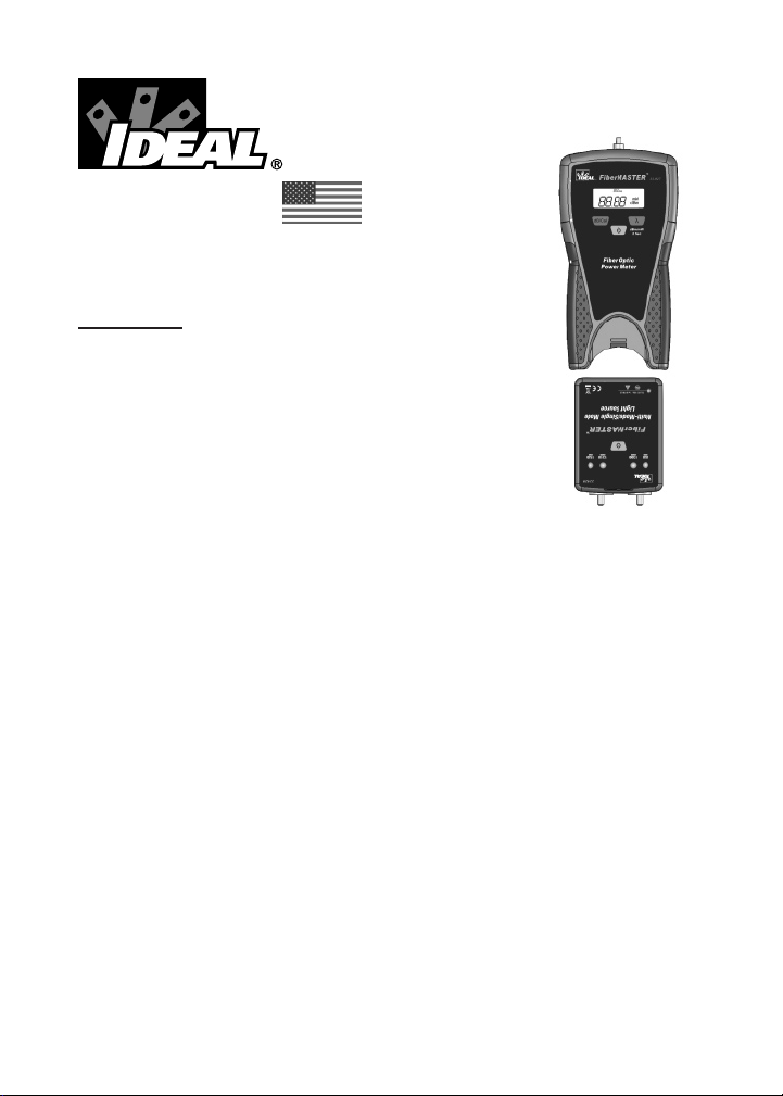
#33-931
FiberMASTER
TM
Fiber Optic Testing Kit
Instruction Manual
Introduction
The IDEAL FiberMASTERTM ber optic testing kit allows
the user to measure absolute power and calculate the
loss of ber optic links at several wavelengths. Absolute
power measurements are helpful when trouble shooting
equipment that may not be operating properly. The dB
calibration feature allows the operator to set a reference
level to the light source and directly read the loss of ber
optic links without needing to manually calculate the values. The unique form
factor allows the light source to be docked neatly within the power meter. This
makes the kit compact for easy storage while still allowing full operation of both
the source and meter.
Product Features
• 850, 1300/1310, 1490 and 1550 wavelength measurement capability
on power meter
• 850/1300/1310/1550nm laser light source (33-931 kit)
• Power measurement in dBm and µW, loss display in dB
• Power meter auto power off
• Operates on standard AAA batteries, three in each unit
• Includes universal adapter for power meter and ST, SC and FC adapters
for light source
• Includes rugged carrying pouch, multimode and single mode SC jumpers
and calibration coupler
1
Page 2

ADVICE AND PRECAUTIONS
Laser Warning:
• Do not look inside the optical ber port when the FiberMASTER is
operating. The emissions can be dangerous and cause permanent
damage to your vision.
• To prevent damage to the lens, do not insert items other than optical
connectors into the port of the FiberMASTER.
• Do not look into the ber if it is connected to an active device. The
wavelength of the light transmitted by the equipment is invisible to
the human eye and may cause permanent vision damage.
• Always assume that a ber optic cable is connected to an active
device that is emitting dangerous, invisible light.
General Operation
FiberMASTER operates in two basic modes; absolute power measurement
and relative power measurement.
Absolute power measurement is the measure of the strength of the light
energy coming into the power meter. This mode is indicated by the dBm
(decibel milliwatt) or µW (microwatt) annunciators in the LCD display. This
mode is helpful when measuring the output of an optical device to determine
if it is operating within its specications. For example, most ber optic
network devices specify their typical output power in dBm. By connecting the
FiberMASTER power meter to the output of a network device the direct power
can be instantly measured to isolate a faulty transmitter.
Relative power measurements are used to calculate the difference in power
between two measurements. This mode is indicated by the dB annunciator
in the LCD panel. This mode is used mostly by installers when measuring
ber optic cabling from end-to-end to determine the link loss of the system.
To use this mode, the power meter must rst be connected to a stable light
source then that power level in stored in the meter’s memory. Then future
measurements are compared to the stored reference value and the difference
is calculated and displayed as dB.
2
Page 3
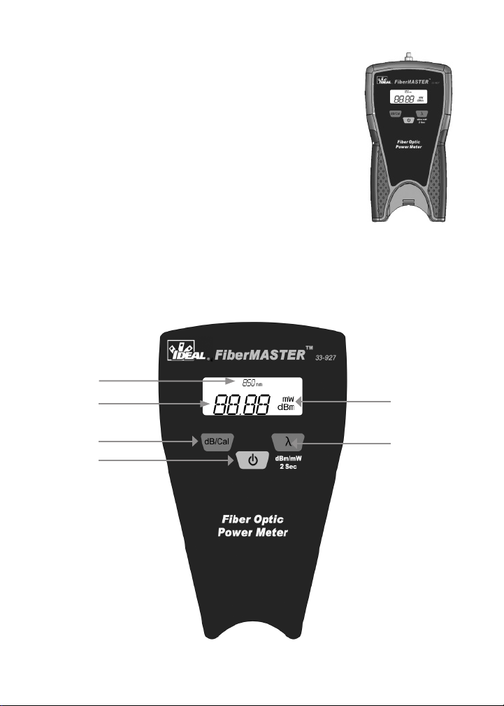
Power Meter Display and Functions
1. Wavelength measurement annunciator.
2. Numeric display for power and loss measurements.
Also displays “null” when power is below detection
level.
3. Decibel toggle button. Press to change between power
measurement mode (dBm) and loss calculation mode
(dB). Changing to dB mode automatically stores the
current input level as the reference for loss calculations.
4. Power button.
5. Unit of measure annunciator, displays either dBm, dB or µW.
6. Wavelength select and dB/µW toggle button. Press and release to
change wavelength between 850/1300/1310/1490/1550nm. Press and
hold for 2 seconds then release to toggle between dBm and µW modes.
1
2
5
3
6
4
3
Page 4
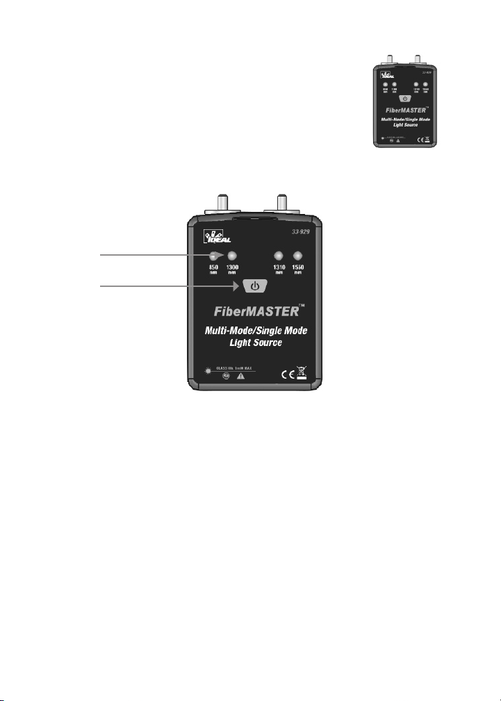
Light Source Indicators and Functions
1. Wavelength LEDs. Lights green to indicate active
source. Blinks red when battery is low. At 3.6V unit will
power off after 10 minutes. At 3.3V unit will power off
after 5 seconds.
2. Power button. Press the toggle wavelength, hold to
power off.
1
2
The power output of the light source will vary slightly during the rst ve
minutes of operation as it warms to operating temperature. To ensure best
measurement accuracy, allow the light source to operate for ve minutes
before calibrating the meter or making measurements.
4
Page 5
Basic Operation
dBm
nm
dBm
nm
-
Measuring Optical Power
Important: When the power meter is rst turned on it self-calibrates to a “no light” condition which is necessary for accurate
measurements. THE DUST COVER MUST REMAIN ON THE
POWER METER PORT WHEN IT IS FIRST TURNED ON.
1. With the dust cap on the power meter, press
the power button. The meter will display ‘null’,
indicating that it is ready to measure and
is currently receiving no power. Press the
wavelength ‘λ’ button to change to the desired
wavelength.
2. Remove the dust cap and connect the meter
to a cable to begin taking measurements. The
default measurement mode is dBm and can
be changed to uW by holding the ‘λ’ button
for 2 seconds then releasing.
In addition to using a separate light source,
the power meter can measure the output
from any optical switch, media converter
or other device as long as its wavelength
is within one of the operating windows of
the 33-927 power meter.
5
Page 6
Measuring Cabling Loss
dBm
nm
-
dBmnmdB
nm
-
Loss measurements are performed to certify a cabling link meets certain
criteria for attenuation. Loss (dB) can be manually calculated by subtracting
the power (dBm) through the cabling under test from the power (dBm) of the
light source when connected directly to the meter. To make this process easier
FiberMASTER includes a calibration function that stores the light source power
level and compares it to future readings and directly displays loss in dB on the
LCD panel.
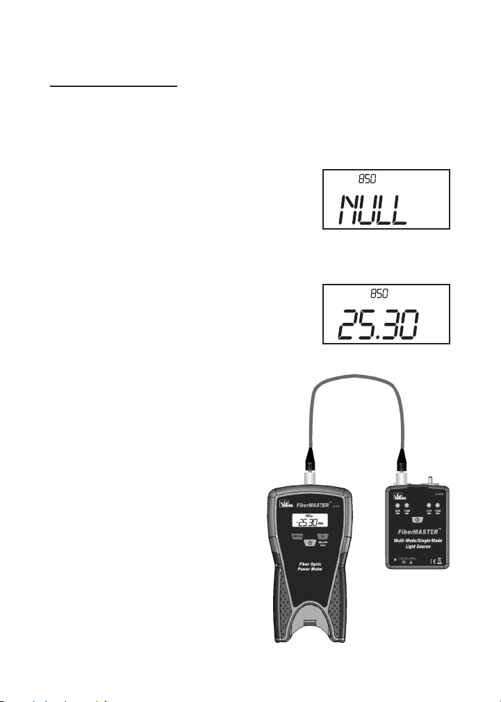
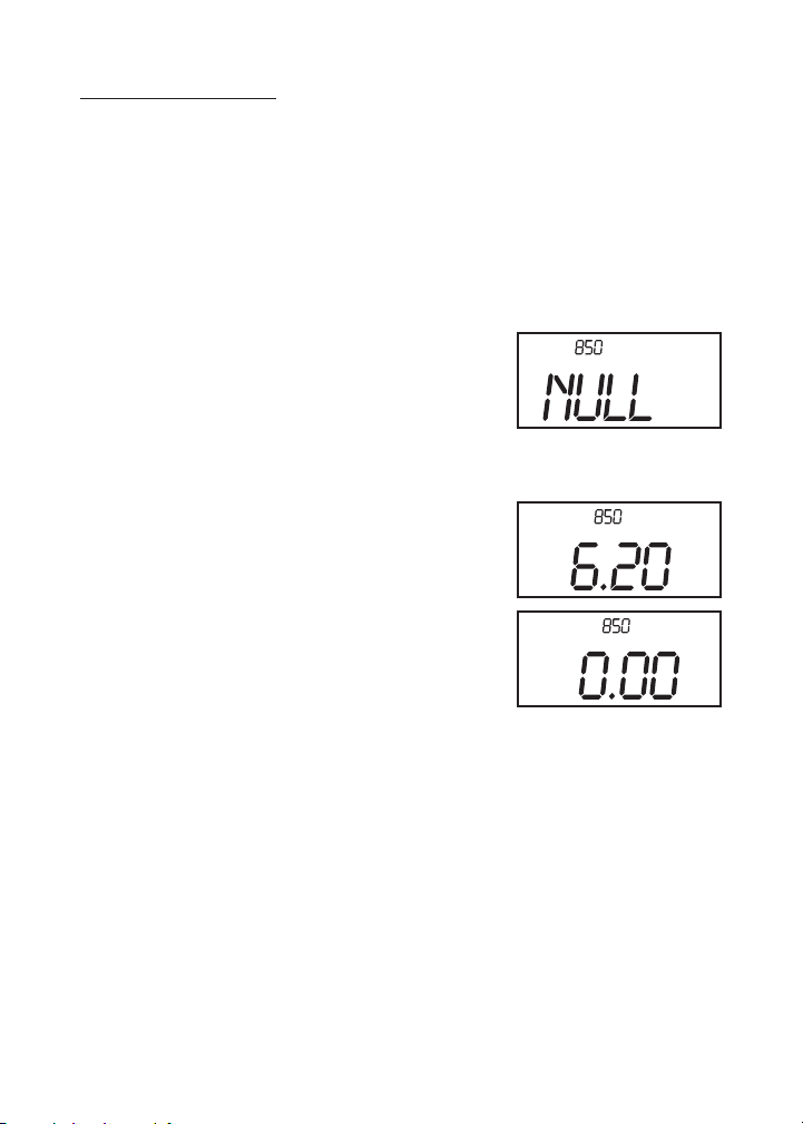
1. With the dust cap on the power meter, press
the power button. The meter will display ‘null’,
indicating that it is ready to measure and
is currently receiving no power. Press the
wavelength ‘λ’ button to change to the desired
wavelength.
2. Set the light source to the desired wavelength.
3. Remove the dust cap and connect the
reference jumpers between the power meter
and light source. The meter will display the
current power dBm from the light source.
4. Press the ‘dB/Cal’ button on the power meter
to store the current value into memory. The
display will now indicate 0.00dB.
5. Remove the coupler from the two reference
jumpers, connect to the cabling under test and
begin making measurements. The display will
indicate the attenuation (dB) compared to the
initial calibration power (dBm).
See diagrams on the following page.
Do not disconnect the reference jumper from the
light source after calibrating the test set. Doing so
will cause inaccuracies and requires recalibration.
6
Page 7
Calibration Procedure Diagrams
dBm
nm
dBm
nm
-
The following diagrams supplement steps 1–4 on the previous page.
Afx the black dust cap
to the input of the power
meter. Clear dust caps
allow ambient light to
pass and cannot be used. Turn on the power meter
and wait for ‘null’ to be displayed on the LCD. The
meter is now ready to use.
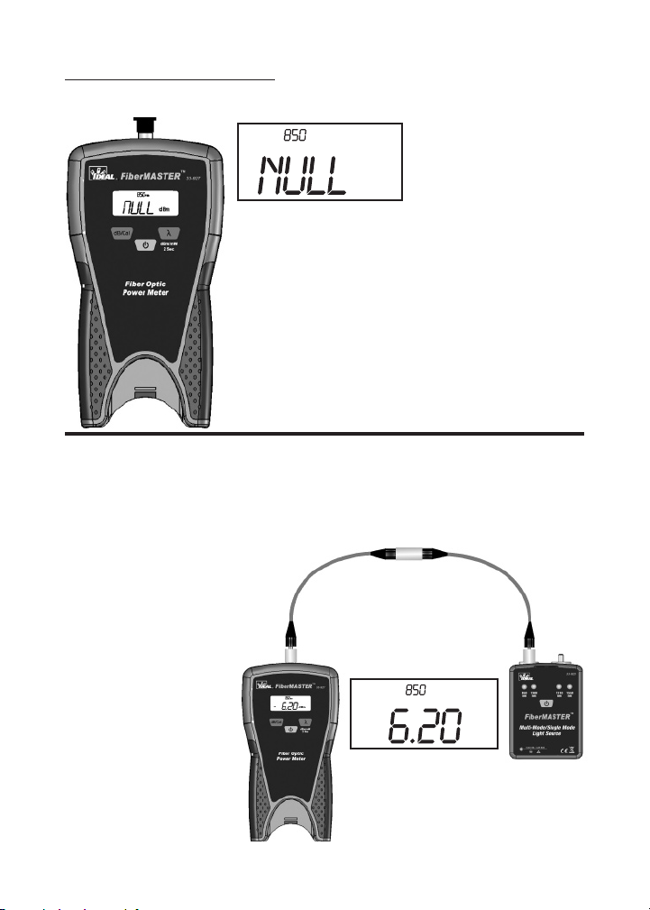
Connect known good reference jumpers between the light source and power
meter. In this example two jumpers are used in conjunction with a coupler.
This conguration allows the jumpers to be connected directly to a patch panel
when making measurements. A single jumper can also be used as long as it
is not disconnected from the light source after the calibration process.
The LCD will display the
current power level at the
power meter input. Typical
values for the 33-929
light sources are -6 to
-7dBm. Levels lower than
this (ex -15dBm) indicate
excessive loss in the
reference jumpers.
New jumpers should
be used.
7
Page 8

Press the ‘dB/Cal’ button
dB
nm
-
dB
nm
-
to store the reference
value. The LCD will
display ‘0.00dB’.
The meter is now measuring
loss.
Repeated pressing of the
‘dB/Cal’ button again will
change between the dBm
power measurement mode
and dB loss measurement
mode. Each time the meter
enters the dB mode it stores the current power level as a new reference level.
Once the calibration value is set, do not toggle out of the dB mode. Otherwise
it will be necessary to perform the calibration step again.
The meter does not store a separate reference value for each wavelength.
When changing wavelengths repeat the jumper reference procedure.
Disconnect the two
reference jumpers and
connect to the cabling
under test. The meter will
display the total loss of all
components between the
two reference jumpers.
8
Page 9

Reference Information
dB vs. Power Table
dB Loss % of Power Remaining % of Power Lost
1 79.00% 21.00%
2 63.00% 37.00%
3 50.00% 50.00%
4 40.00% 60.00%
5 32.00% 68.00%
6 25.00% 75.00%
7 20.00% 80.00%
8 16.00% 84.00%
9 12.00% 88.00%
10 10.00% 90.00%
11 8.00% 92.00%
12 6.30% 93.70%
13 5.00% 95.00%
14 4.00% 96.00%
15 3.20% 96.80%
16 2.50% 97.50%
17 2.00% 98.00%
18 1.60% 98.40%
19 1.30% 98.70%
20 1.00% 99.00%
25 0.30% 99.70%
30 0.10% 99.90%
40 0.01% 99.99%
50 0.001% 99.90%
Maintenance
Clean the case with a damp cloth, do not use detergents. Clean the optical
ports with lint free tissues and swabs designed for ber optic components
and use 99% pure isopropyl alcohol and de-ionized water. Do not blow into
the optical ports.
Service and replacement parts
This unit has no user serviceable parts. To obtain service call Technical
Support at 800-854-2708 or 858-627-0100.
9
Page 10

Power Meter Specications
Wavelength 850, 1300, 1310, 1490, 1550nm
Detector InGaAs
Measurement Range -60 to +3dBm
Accuracy ±5%
Display Resolution .01
Connector Universal 2.5mm w/ FC adapter
Power Supply AAA Alkaline Battery x 3
Operating Time 360 hours
Operating Temp -10 to +60°C
Storage Temp -25 to +70°C
Light Source Specications
Wavelength 850/1300/1310/1550nm laser diode
Output Power -6 to -7 dBm Typical
Stability .05dB after 15min, 0.1dB over 8 hrs
Connector 2.5mm w/ ST, SC, FC adapters
Power Supply AAA Alkaline Battery x 3
Operating Time 40 hours
Operating Temp -10 to +60°C
Storage Temp -25 to +70°C
Limited Warranty
This instrument is warranted to the original purchaser against defects in material or workmanship for one year from the date of purchase. During this warranty period, IDEAL INDUSTRIES,
INC. will, at its option, replace or repair the defective unit, subject to the verication of the
defect or malfunction. This warranty does not apply to malfunctions resulting from abuse,
neglect, accident, unauthorized repair, alteration or unreasonable use of the instrument.
Any implied warranties arising out of the sale of an IDEAL product, including but not limited
to implied warranties of merchantability and tness for a particular purpose, are limited to the
above. The manufacturer shall not be liable for loss of use of the instrument or other incidental or consequential damages, expenses or economic loss, or for any claim or claims for such
damage, expenses or economic loss.
State laws vary, so the above limitations or exclusions may not apply to you. This warranty
gives you specic legal rights, and you may also have other rights, which may vary from
state to state.
Warranty limited solely to repair or replacement; no warranty or merchantability, tness for
a particular purpose or consequential damages.
10
Page 11

IDEAL INDUSTRIES, INC.
Sycamore, IL 60178, U.S.A.
800-435-0705 Customer Assistance, 800-854-2708 Technical Support
www.idealindustries.com
6510-92-0001 Rev C Made in China / Fabriqué aux China / Fabricado en China
11
 Loading...