

Page 1

installation and
servicing
classic
Your Ideal installation and servicing guide
See reverse for
classic
users guide
When replacing any part on this appliance use only spare parts that you can be
assured conform to the safety and performance specification that we require. Do not
use reconditioned or copy parts that have not been clearly authorised by Ideal Boilers.
For the very latest copy of literature for specification purposes please visit our website
www.idealboilers.com where you will be able to download the relevant information in pdf format.
HE9, HE12, HE15, HE18
For details of document amendments, refer to page 3
January 2008 UIN 201 850 A06
Page 2

2
classic HE - Installation & Servicing
Page 3

DOCUMENT AMENDMENTS
Relevant Installation changes implemented in this book from Mod Level ............ A05 (Oct 06) to A06 (Jan 08)
• Various Pages
Company Name Change.
• Page 26 & 27, Frames 39 & 40 - Condensate Pipe Termination Configurations
BS6798 recommends that a second trap and an air break are required where the siphon trap within the boiler is less than
75mm for configuration 2 and 3
• Page 27, Frame 40 - Condensate Pipe Termination Configurations
Statement added with ref. to termination into a down pipe.
• Page 33, Frame 54 - Burner and Air Box Removal
Item No. 5 added.
• Users Guide, Page 2 - Important Notes
2 new bullet points added.
Ideal Stelrad Group reserve the right to vary specification without notice
classic HE - Installation & Servicing
3
Page 4
GENERAL
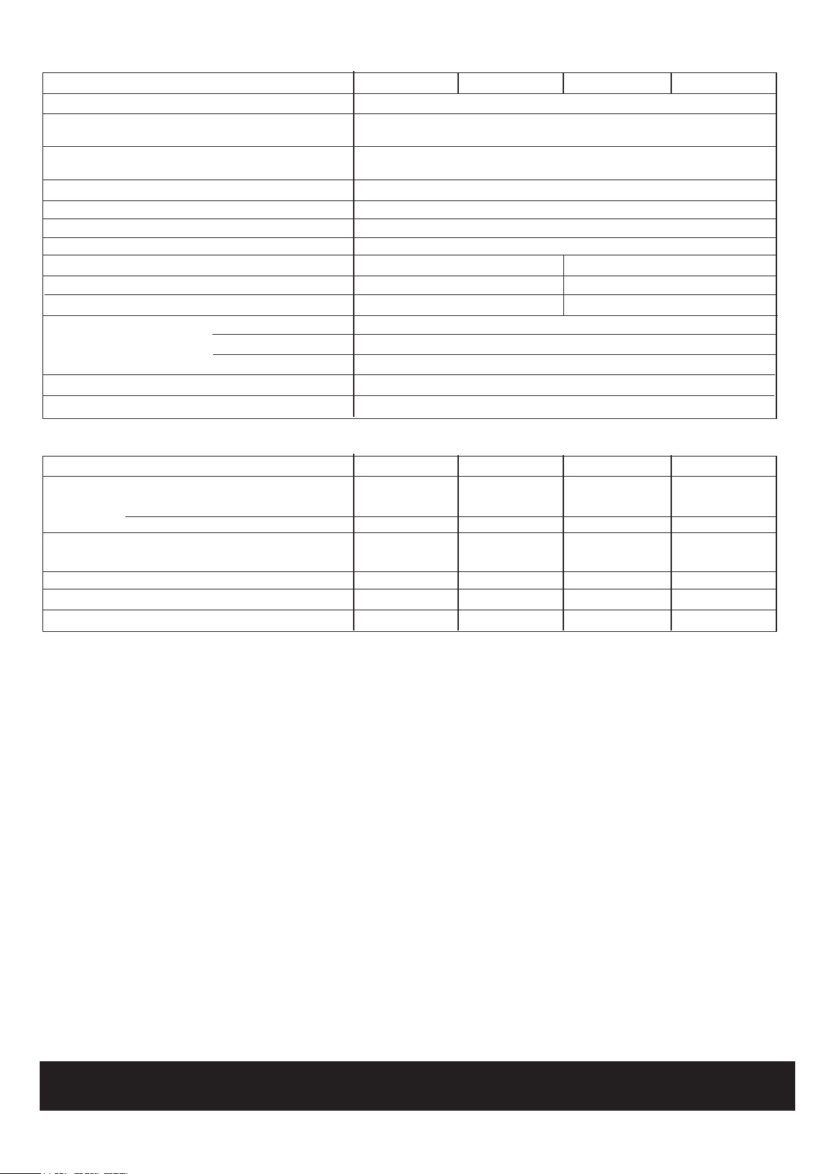
Table 1 - General Data
Boiler Size HE9 HE12 HE15 HE18
Gas supply connection (in. BSP) Rc 1/2 (1/2) 1/2" (BSP Female)
Flow connection 22mm
copper
Return connection 22mm
copper
Maximum static water head m (ft.) 30.5 (100)
Minimum static water head m (ft.) 0.45 (1.5)
Electrical supply 230 V 50 Hz Boiler power consumption; 100W
Fuse rating External; 3A Internal; F1A to BS.4265
Water content litre (gal.) 3.0 (0.67) 3.95 (0.87)
Packaged Weight kg (lb) 45 (99) 50 (110)
Maximum installation weight kg (lb) 40 (88) 45 (99)
Boiler size Height mm (in.) 700 (27.5)
Width mm (in.) 380 (15.0)
Depth mm (in.) 280 (11.25)
Flue duct diameter mm (in.) 100 (4.0)
Flue duct length (max) m (ft) 3 (9.8)
Table 2 - Performance Data
Boiler Size HE9 HE12 HE15 HE18
Input 'Q' Nett CV kW (Btu/h) 9.4 (32,100) 12.6 (43,000) 15.7 (53,600) 18.9 (64,500)
Gross CV kW (Btu/h) 10.5 (35,800) 14.0 (47,800) 17.4 (59,400) 20.9 (71,300)
Gas Consumption l/s (cu.ft/h) 0.27 (34.3) 0.36 (45.8) 0.45 (57.2) 0.54 (68.7)
Output 'P 70
o
C Mean Water temp. kW (Btu/h) 9.0 (30,700) 12.0 (40,900) 15.0 (51,200) 18.0 (61,400)
40oC Mean Water temp. kW (Btu/h) 9.8 (33,400) 13.1 (44,700) 16.2 (55,300) 19.4 (66,200)
Burner Setting Pressure (Hot) mbar (in w.g.) 12.0 (4.8) 10.4 (4.2) 12.3 (4.9) 12.7 (5.1)
Seasonal efficiency (SEDBUK) * Band B [87.2]% [87.2]% [86.8]% [86.8]%
NOx classification Class 3 Class 2 Class 1 Class 1
* The value is used in the UK Government's Standard Assessment Procedure (SAP) for energy rating of
dwellings. The test data from which it has been calculated have been certified by a notified body.
Note. Gas consumption is calculated using a calorific value of
38.7 MJ/m
3
(1038 Btu/ft3) gross or 34.9 MJ/m3 (935 Btu/ft3) nett
To obtain the gas consumption at a different calorific value:-
a. FOR L/S - divide the gross heat input (kW) by the gross C.V.
of the gas (MJ/m
b. FOR FT
3
/H - divide the gross heat input (Btu/h) by the gross
3
)
C.V. of the gas (Btu/ft3)
Key to symbols
GB = United Kingdom IE = Ireland (Countries of destination)
PMS = Maximum operating pressure of water
C
= A room sealed appliance designed for connection via
12 C32
ducts to a horizontal or vertical terminal which admits
fresh air to the burner and discharges the products of
combustion to the outside through orifices which, in
this case, are concentric. The fan is down stream of
the combustion chamber.
I
= An appliance designed for use on 2nd Family gas,
2H
Group H only.
CAUTION.
To avoid the possibility of injury during the installation, servicing or cleaning
of this appliance, care should be taken when handling edges of sheet steel components
4
classic HE - Installation & Servicing
Page 5
GENERAL
classic HE
Natural Gas only
Boiler size G.C. Appliance No. PI No.
(Benchmark No.)
HE9 41-415-58 87 BQ 10
HE12 41-415-59 87 BQ 10
HE15 41-421-45 87 BQ 10
HE18 41-421-46 87 BQ 10
Destination Countries: GB, IE
CONTENTS
Air Supply. ..................................................................... 9
Benchmark Commissioning Checklist ..................... 46
Boiler Clearances .........................................................7
Boiler Exploded View ................................................. 13
Electrical Connections ............................................... 28
Electrical Regulations ................................................ 10
Extension Ducts - Fitting ............................................ 22
External Controls ........................................................28
Fault Finding ................................................................ 42
Flue Installation ............................................................. 8
Rear installation ...................................................... 16
Side installation .......................................................19
Gas Safety ..................................................................... 6
Gas Supply .................................................................... 8
Initial Lighting . .......................................................31,32
Installation ............................................................ 13-32
Mandatory Requirements ............................................ 6
Pump ........................................................................... 10
Safe Handling ................................................................ 6
Servicing ............................................................... 33-41
Short List of Parts ...................................................... 43
Spares Replacement ................................................. 35
System Electrical Diagrams .................................29,30
Terminal Guards. .......................................................... 8
Water and Systems ..................................................... 9
Water Treatment ..........................................................9
For GB, to comply with Building Regulations Part L1 (Part J in Scotland) the boiler should be fitted in accordance with the
manufacturer's instructions. Self-certification that the boiler has been installed to comply with Building Regulations can be
demonstrated by completing and signing the Benchmark Commissioning Checklist.
BENCHMARK COMMISSIONING CHECKLIST
Boiler Page
Make and model ....................................................... 5
Appliance serial no. on data badge ....................... 1 3
SEDBUK No. % .........................................................4
Controls
Time and temperature control to heating ......... 29/30
Time and temperature control to hot water ...... 29/30
Heating zone valves .......................................... 29/30
TRV's ......................................................................... 9
Auto bypass ............................................................... 9
Boiler interlock ..........................................................9
For all boilers
Flushing to BS.7593 .................................................9
Inhibitor...................................................................... 9
Central heating mode
Heat input ................................................. to be calculated
Burner operating pressure ....... measure and record
Central heating flow temp. ........ measure and record
Central heating return temp. ..... measure and record
For combination boilers only
Scale reducer .........................................................n/a
Hot water mode
Heat input ...............................................................n/a
Max. operating burner pressure ............................n/a
Max. operating water pressure ..............................n/a
Cold water inlet temp .............................................n/a
Hot water outlet temp. ............................................n/a
Water flow rate at max. setting ...............................n/a
For condensing boilers only
Condensate drain .................................................. 26
For all boilers: complete, sign & hand over to customer
For assistance see Technical Helpline on the back page
Page
NOTE TO THE INSTALLER:
THE BENCHMARK COMMISSIONING
CHECKLIST AND LEAVE THESE
INSTRUCTIONS WITH APPLIANCE
classic HE - Installation & Servicing
COMPLETE
5
Page 6

GENERAL
INTRODUCTION
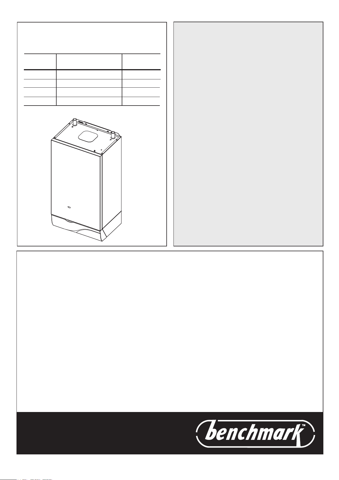
The classic HE 9, 12, 15 and 18 are a range of automatically fully
controlled, wall mounted, balanced flue, fanned, high efficiency,
condensing gas boilers.
The primary heat exchanger is cast iron. The secondary heat
exchanger is aluminium. The boiler casing is of white enamelled
mild steel.
The boiler casing has a removable controls pod containing a drop-down
door. The boiler thermostat is located behind the drop- down door.
Note. These boilers cannot be used on systems which include
gravity circulation.
See Frame 1 for details of the correct boiler tappings to use.
The boilers are supplied with a standard flue kit suitable for rear
outlet from 114 mm (4
Side outlet applications require the optional extra side outlet kit.
The boilers are suitable for connection to the following open
vented or sealed systems:
• Fully pumped CH and indirect DHW
• Pumped heating only.
• Pumped indirect DHW only.
1/2") to 705 mm (30 1/2").
SAFE HANDLING
This boiler may require 2 operatives to move it to its installation
site, remove it from its packaging base and during movement
into its installation location. Manoeuvring the boiler may include
the use of a sack truck and involve lifting, pushing and pulling.
Caution should be exercised during these operations.
Operatives should be knowledgeable in handling techniques
when performing these tasks and the following precautions
should be considered:
• Grip the boiler. Refer to Frame 18.
• Split the boiler down to reduce the weight, e.g. remove casing
and hardware pack. Refer to Frame 9.
• Be physically capable.
• Use PPE as appropriate, e.g. gloves, safety footwear.
During all manoeuvres and handling actions, every attempt
should be made to ensure the following unless unavoidable
and/or the weight is light.
• Keep back straight.
• Avoid twisting at the waist.
• Avoid upper body/top heavy bending.
• Always grip with the palm of the hand.
• Use designated hand holds.
• Keep load as close to the body as possible.
• Always use assistance if required.
OPTIONAL EXTRA KITS
FLUING:
z Flue Extension Ducts. (1000mm long) up to 3m
o
z 90
Elbow Kit (60/100 dia maximum no. per installation)
up to 2 elbows
o
z 45
Elbow Kit (60/100 dia maximum no. per installation)
up to 2 elbows
z Side Outlet Kit
z Vertical Connector Kit
z Flue Finishing Kit
z Roof Flue Kit
z High Level Flue Outlet Kit
z Flue Deflector Kit
OTHER OPTIONAL KITS:
z Downward Piping Kit
z Condensate Pump Kit
6
CURRENT GAS SAFETY (INSTALLATION AND USE)
REGULATIONS OR RULES IN FORCE.
The appliance is suitable only for installation in GB and IE and
should be installed in accordance with the rules in force.
In GB, the installation must be carried out by a CORGI
Registered Installer. It must be carried out in accordance with
the relevant requirements of the:
• Gas Safety (Installation and Use) Regulations
• The appropriate Building Regulations either The Building
Regulations, The Building Standards (Scotland), Building
Regulations (Northern Ireland).
• The Water Fittings Regulations or Water byelaws in
Scotland.
• The Current I.E.E. Wiring Regulations.
Where no specific instructions are given, reference should be
made to the relevant British Standard Code of Practice.
In IE, the installation must be carried out by a Competent
Person and installed in accordance with the current edition of
I.S.813 "Domestic Gas Installations", the current Building
Regulations and reference should be made to the current ETCI
rules for electrical installation.
Detailed recommendations are contained in the following British
Standard Codes of Practice:
BS.6891 Low pressure installation pipes.
BS.6798 Installation of gas fired hot water boilers of rated input
not exceeding 70 kW.
BS.5449 Forced circulation hot water systems.
BS.5546 Installation of gas hot water supplies for domestic
purposes (2nd Family Gases).
BS.7593 Treatment of water in domestic hot water central
heating systems.
BS.5440.1 Flues for gas appliances of rated input not exceeding
70 kW.
BS.5440.2 Ventilation for gas appliances of rated input not
exceeding 70 kW.
Health & Safety Document No. 635
The Electricity at Work Regulations, 1989.
Manufacturer’s notes must NOT be taken in any way as overriding
statutory obligations.
IMPORTANT. These appliances are certificated by the British
Standards Institution for safety and performance. It is, therefore,
important that no external control devices, e.g. flue dampers,
economisers etc., are directly connected to these appliances unless covered by these Installation and Servicing instructions or
otherwise recommended by Ideal Stelrad Group in writing.
If in doubt please enquire.
Any direct reconnection of a control device not approved by Ideal
Stelrad Group could invalidate the BSI Certification and the normal
appliance warranty. It could also infringe the Gas Safety Regulations
and the above regulations.
SAFE HANDLING OF SUBSTANCES
Care should be taken when handling the boiler insulation panels
which can cause irritation to the skin. No asbestos, mercury or
CFCs are included in any part of this boiler.
LOCATION OF BOILER
The boiler must be installed on a flat and vertical wall, capable of
adequately supporting the weight of the boiler and any ancillary
equipment.
The boiler may be fitted on a combustible wall and insulation
between the wall and the boiler is not necessary - unless required
by the local authority. The boiler must not be fitted outside.
Timber Framed Buildings
If the boiler is to be fitted in a timber framed building it should be
fitted in accordance with the Institute of Gas Engineering document
IGE/UP/7:1998.
continued on page 8 . . . . . . . . .
classic HE - Installation & Servicing
Page 7
1
cla7635
(15 3/8")
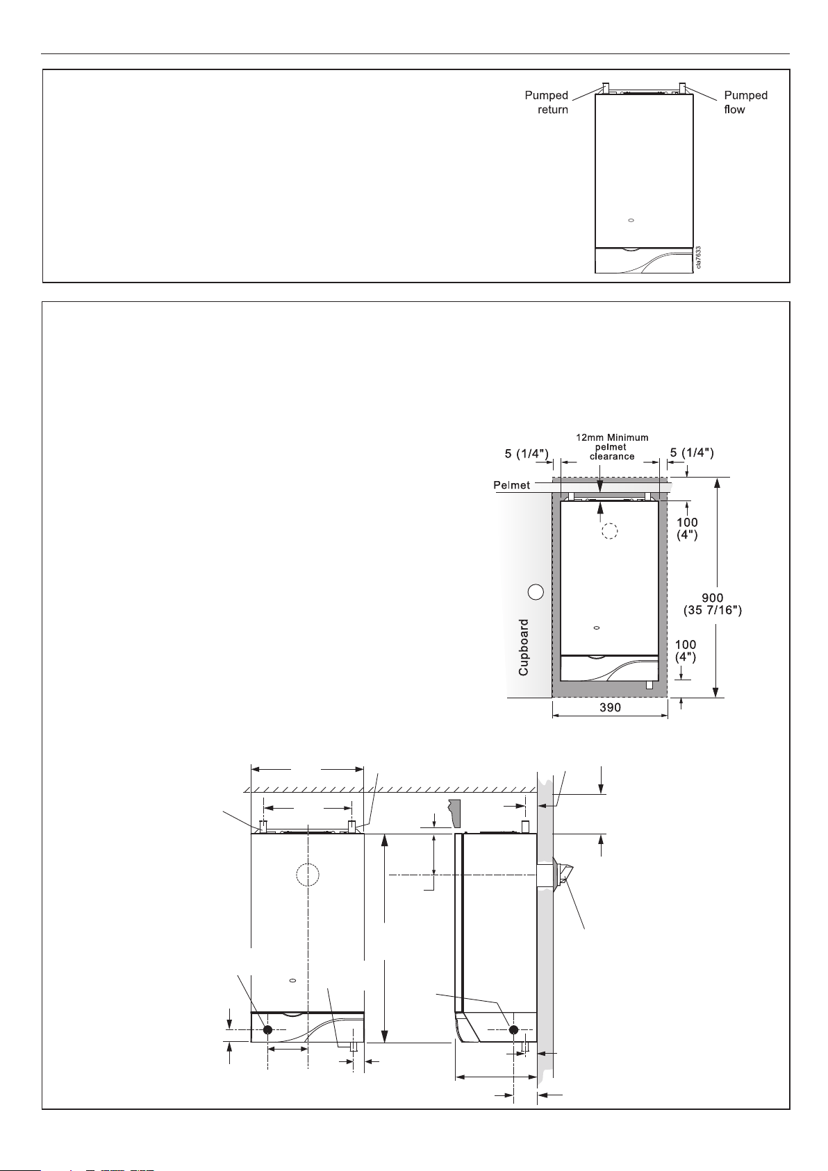
BOILER WATER CONNECTIONS
This appliance in NOT suitable for use in a direct
hot water system or for gravity circulation.
2
BOILER CLEARANCES
GENERAL
The following minimum clearances must
be maintained for operation and servicing.
Additional space will be required for
installation, depending upon site
conditions.
Side and Rear Flue
a. Provided that the flue hole is cut
accurately, e.g. with a core drill, the flue
can be installed from inside the
building.
Installation from inside ONLY
b. If a core boring tool is to be used inside
the building; the space in which the
boiler is to be installed must be at least
wide enough to accommodate the tool.
Front View Side View
Pumped
return
pipe
Front clearance: 450mm (17 3/4") from the front of the boiler casing.
Minimum front clearance when built behind a concealed panel is 5mm (
provided that the top and bottom of the casing is not enclosed and the side
clearance is 40mm (2") at both sides.
See also Table 4.
380
(15")
296
(115/8")
Pumped
flow pipe
12 (1/2")
44
(1 3/4")
100
(4")
1
/4")
Gas
connection
20 (3/4")
classic HE - Installation & Servicing
133
(5 1/4")
Condensate
drain point
141
(5 9/16")
700
(27 1/2")
Gas
connection
70 (2 3/4")
280 (11")
Flue
terminal
cla8230
38 (1 1/2")
64 (2 1/2")
7
Page 8
GENERAL
Bathrooms
This range of appliances is rated IP 1XB.
The boiler may be installed in any room or internal space, although
particular attention is drawn to the requirements of the current
I.E.E. (BS.7671) Wiring Regulations and, in Scotland, the electrical
provisions of the building regulations applicable in Scotland with
respect to the installation of the boiler in a room or internal space
containing a bath or shower. For Ireland reference should be
made to the current ETCI rules for electrical installations and
I.S.813:2002.
If the appliance is to be installed in a room containing a bath or
shower then, providing waterjets are not going to be used for
cleaning purposes (such as communal baths/showers), the
appliance can be installed in Zone 3, as detailed in BS.7671.
Where installation will be in an unusual location, special
procedures may be necessary and BS.6798 gives detailed
guidance on this aspect.
Compartment Installations
A compartment used to enclose the boiler MUST be designed
and constructed specially for this purpose.
An existing cupboard or compartment may be used, provided it
is modified for the purpose.
In both cases details of essential features of cupboards/
compartment design, including airing cupboard installation, are
to conform to the following :
z BS. 6798.
z The position selected for installation MUST allow adequate
space for servicing in front of the boiler and for air circulation
around the boiler. Refer to 'Air Supply'.
z For the minimum clearances required for safety and
subsequent service refer to the wall mounting diagram,
Frame 2. In addition, sufficient space may be required to allow
lifting access to the wall mounting plate.
GAS SUPPLY
The local gas supplier should be consulted, at the installation
planning stage, in order to establish the availability of an adequate
supply of gas. An existing service pipe must NOT be used without
prior consultation with the local gas supplier.
The boiler is to be installed only on a gas supply with a governed meter.
A gas meter can only be connected by the local gas supplier or by
a local regional contractor.
An existing meter should be checked, preferably by the gas supplier,
to ensure that the meter is adequate to deal with the rate of gas
supply required. A MINIMUM pressure of 20 mbar MUST be
available at the boiler inlet with the boiler operating.
Installation pipes MUST be fitted in accordance with BS. 6891. In
IE refer to I.S. 813:2002. Pipework from the meter to the boiler
MUST be of an adequate size.
The complete installation MUST be tested for gas soundness and
purged as described in the above code.
FLUE INSTALLATION
Pluming may occur at the terminal so terminal positions which
would cause a nuisance should be avoided.
The flue must be installed in accordance with the
recommendations of BS. 5440-1:2000. In IE refer to I.S. 813:2002.
The following notes are intended for general guidance:-
1. The boiler MUST be installed so that the terminal is exposed
to external air.
2. It is important that the position of the terminal allows the free
passage of air across it at all times.
3. Minimum acceptable spacing from the terminal to obstructions
and ventilation openings are specified in Table 3.
4. Where the lowest part of the terminal is fitted less than 2m
(6'6") above a balcony, above ground or above a flat roof to
which people have access then the terminal MUST be protected
by a purpose designed guard.
Terminals guards are available from boiler suppliers - ask for
TFC Flue Guard, Model No. K6-round, plastic coated. In case of
difficulty seek advice from:
Grasslin (UK) Ltd., Tower House, Vale Rise, Tonbridge,
Kent TN9 1TB.
Tel: +44 (0) 1732 359 888. Fax: +44 (0) 1732 354 445
www.tfc-group.co.uk
Ensure that the guard is fitted centrally.
5. The flue assembly shall be so placed or shielded as to prevent
ignition or damage to any part of any building.
6. The air inlet/products outlet duct and the terminal of the boiler
MUST NOT be closer than 25mm (1") to combustible material.
Detailed recommendations on the protection of combustible
material are given in BS.5440-1:2000. In IE refer to I.S. 813:2002.
IMPORTANT. It is absolutely ESSENTIAL to ensure, in practice, that
products of combustion discharging from the terminal cannot reenter the building or any other adjacent building through ventilators,
windows, doors, other sources of natural air infiltration, or forced
ventilation/air conditioning.
If this should occur, the appliance MUST be turned OFF, labelled
'unsafe' and corrective action taken.
Table 3 - Balanced Flue Terminal Position
Flue Terminal Positions
1. Directly below or alongside an opening
window, air vent or other ventilation opening. 300mm (12")
2. Below guttering, drain pipes or soil pipes. 25mm ( 1")*
BS5440-1 2000 75mm (3")
3. Below eaves. 25mm (1")*
BS5440-1 2000 200mm (8")
4. Below balconies or a car port roof. 25mm (1")*
BS5440-1 2000 200mm (8")
5. From vertical drain pipes or soil pipes. 25mm (1")*
BS5440-1 2000 150mm (6")
6. From an internal or external corner or to a 25mm (1")*
boundary along side the terminal. BS5440-1 2000 300mm (12")
7. Above adjacent ground, roof or balcony level. 300mm (12")
8. From a surface or a boundary facing the terminal. 600mm (24")
9. From a terminal facing a terminal. 1,200mm (48")
10. From an opening in a car port
(e.g. door or window) into dwelling. 1,200mm (48")
11. Vertically from a terminal on the same wall. 1,500mm (60")
12. Horizontally from a terminal on the wall. 300mm (12")
Vertical Terminals
13. Above the roof pitch with roof slope of all angles. 300mm (12")
Above flat roof. 300mm (12")
14. From a single wall face. 600mm (24")
From corner walls. 1000mm (40")
Twin Flue Applications
15. Centre distance between air inlet and flue
outlet ducts. 120mm (5")
* Only one reduction down to 25mm is allowable per installation
otherwise BS5440-1 2000 dimensions must be followed.
Min. Spacing*
8
classic HE - Installation & Servicing
Page 9
GENERAL
TERMINAL
The terminal assembly can be adapted to accommodate various
wall thicknesses. Refer to Frame 10.
AIR SUPPLY
Detailed recommendations for air supply are given in BS.5440:2.
In IE refer to I.S. 813:2002.
The following notes are for general guidance:
1. It is NOT necessary to have a purpose provided air vent in the
room or internal space in which the boiler is installed.
2. If the boiler is to be installed in a cupboard or compartment,
permanent air vents are required (for cooling purposes) in
the cupboard/compartment, at both high and low levels. The
air vents must either communicate with room/internal space,
or be direct to outside air. The minimum effective areas of the
permanent air vents, required in the cupboard/compartment,
are specified in Table 4 and are related to maximum rated
heat input.
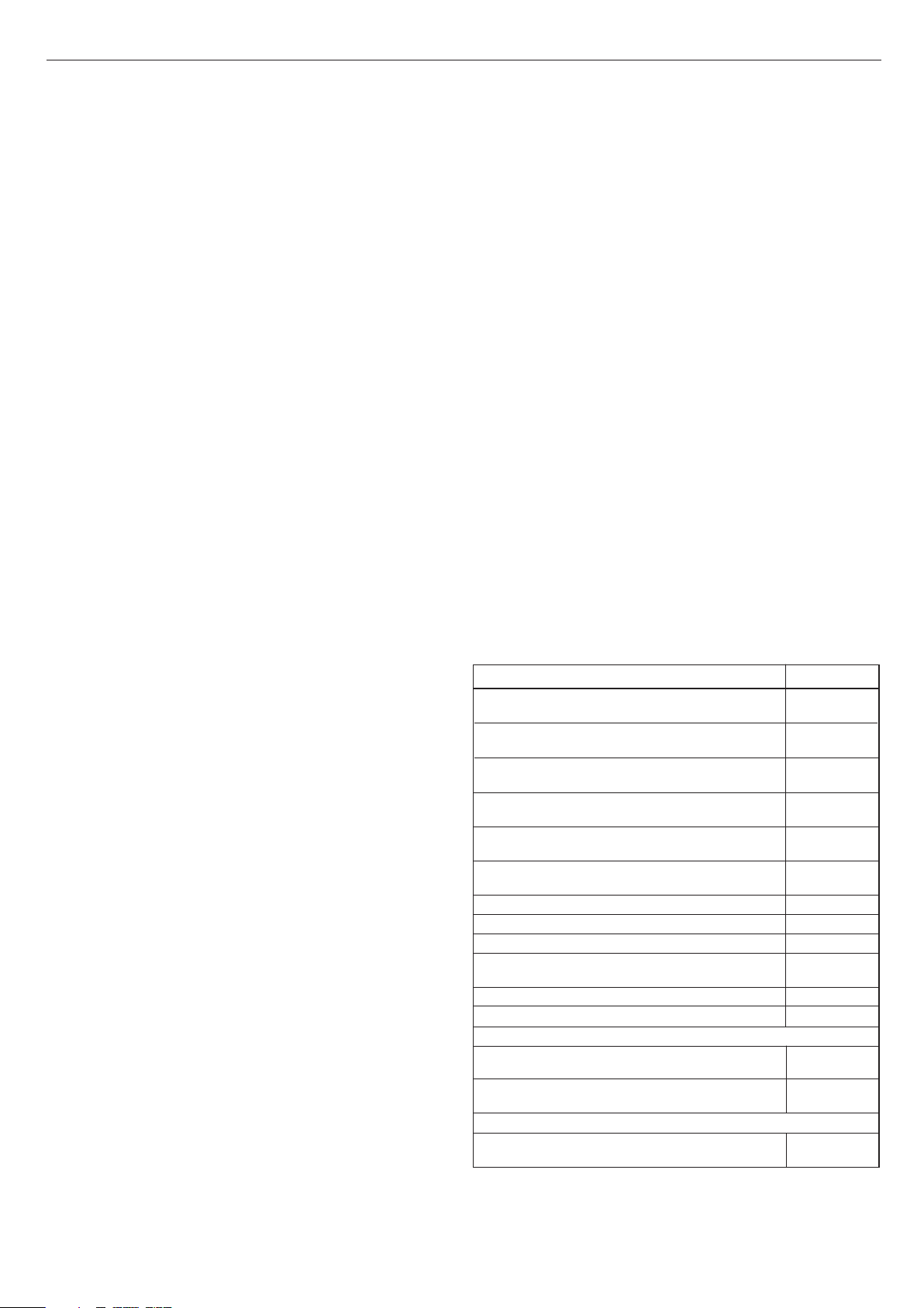
Table 4 - High and low vent areas
Boiler Air from room/internal Air direct from
space, cm (in2 ) outside, cm (in2)
HE9 102 (16) 51 (8)
HE12 135 (21) 68 (11)
HE15 170 (26) 83 (13)
HE18 198 (31) 102 (16)
3. Both air vents MUST communicate with the same room or
internal space or MUST be on the same wall to outside air.
4. In siting the air vents care must be taken to avoid the freezing
of pipework.Water circulation system.
WATER CIRCULATION SYSTEM
The boiler must NOT be used for direct hot water supply. For the
types of system and correct piping procedure refer to 'Introduction'
and Frame 1.
The central heating system should be in accordance with BS.6798
and, in addition, for Smallbore and Microbore systems, BS. 5449.
The domestic hot water system, if applicable, should be in
accordance with the relevant recommendations of BS. 5546. Copper
tubing to BS. 2871:1 is recommended for water carrying pipework.
The hot water storage cylinder MUST be of the indirect type and
should preferably be manufactured of copper.
Single feed, indirect cylinders are not recommended and MUST
NOT be used on sealed systems.
The appliances are NOT suitable for gravity central heating, nor
are they suitable for the provision of gravity domestic hot water.
The hot water cylinder and ancillary pipework, not forming part of
the useful heating surface, should be lagged to prevent heat loss
and any possible freezing - particularly where pipes run through
roof spaces and ventilated under floor spaces.
Boilers not fitted to a sealed system must be vented.
IMPORTANT
A minimum length of 1m of copper pipe MUST be fitted to both
flow and return connections from the boiler before connection to
any plastic piping. This applies to ALL types of installation.
Draining taps MUST be located in accessible positions, which
permit the draining of the whole system - including the boiler
classic HE - Installation & Servicing
and hot water storage vessel. They should be at least
nominal size and be in accordance with BS. 2879.
The boiler is fitted with a special drain plug, which is provided,
to drain the BOILER ONLY, in the event of the system drain plug
being unable to do so. The hydraulic resistance of the boilers,
at MAXIMUM OUTPUT with an 11
differential, are shown in Table 5.
Maximum boiler operating temperature should be 82
Table 5 - Water flow rate and pressure loss
Boiler Size HE 9 1 2 1 5 1 8
Boiler kW 9.0 12 15 18
Output Btu/h x 1000 30.7 40.9 50.2 60.4
Water Flow l/min 11.7 15.6 19.5 23.4
Rate gal/h 155 206 258 309
Pressure mbar 54.0 93.5 98.4 142.5
Loss in wg 21.6 37.4 39.3 57
O
C (20OF) temperature
1/2" BSP
o
C (180oF).
WATER TREATMENT
These boilers incorporate a cast iron heat exchanger and an
aluminium heat exchanger.
IMPORTANT. The application of any other treatment to this
product may render the guarantee of Ideal Stelrad Group
INVALID.
Ideal Stelrad Group recommend Water Treatment in accordance
with the Benchmark Guidance Notes on Water Treatment in
Central Heating Systems.
Ideal Stelrad Group recommend the use of Fernox, GE Betz
Sentinel or Salamander water treatment products, which must
be used on accordance with the manufacturers instructions.
For further information contact:
Fernox Manufacturing Co. Ltd, Cookson Electronics, Forsyth Road,
Sheerwater, Woking, Surrey. GU21 5RZ. Tel. +44 (0) 1799 521133
or
Sentinel Performance Solutions,
The Heath Business & Technical Park, Runcorn, Cheshire
WA7 4QX. Tel: 0800 389 4670. www.sentinel-solutions.net
or
Salamander Engineering Ltd, Unit 24, Reddicap Trading Estate,
Sutton Coldfield, West Midlands B75 7BU. Tel. +44 (0) 121 378 0952
Notes.
1. It is most important that the correct concentration of the water
treatment products is maintained in accordance with the
manufacturers' instructions.
2. If the boiler is installed in an existing system any unsuitable
additives MUST be removed by thorough cleansing.
BS7593:1992 details the steps necessary to clean a
domestic heating system.
3. In hard water areas, treatment to prevent limescale may be
necessary - however the use of artificially softened water is
NOT permitted.
4. Under no circumstances should the boiler be fired before the
system has been thoroughly flushed.
BOILER CONTROL INTERLOCKS
Ideal Stelrad Group recommend that heating systems utilising
full thermostatic radiator valve control of temperature in
individual rooms should also be fitted with a room thermostat
controlling the temperature in a space served by radiators not
fitted with such a valve as stated in BS. 5449.
continued . . . .
9
Page 10
GENERAL
System
return
Connections
to boiler
Inverted cold
feed entry
System
flow to
pump
150 (6")
Max
15mm
Cold
feed
450 (17
3
/4")
Mimimum
450 (17
3
/4")
Mimimum
22mm
Open vent
Feed / expansion
cistern
Water
level
(cold)
cla7840
Central heating systems controls should be installed to
ensure the boiler is switched off when there is no demand for
heating or hot water.
When thermostatic radiator valves are used, the space heating
temperature control over a living / dining area or hallway having
a heating requirement of at least 10% of the boiler heat output
should be achieved using a room thermostat, whilst other
rooms are individually controlled by thermostatic radiator
valves. However, if the system employs thermostatic radiator
valves on all radiators, or two port valves without end switches,
then a bypass circuit must be fitted with an automatic bypass
valve to ensure a flow of water should all valves be in the
closed position.
The point of connection to the mains should be readily accessible
and adjacent to the boiler, except that for bathroom installations; the
point of connection to the mains MUST be situated outside of the
bathroom.
Note.
Where a room sealed appliance is installed in a room containing
a bath or shower then the appliance and any electrical switch or
appliance control utilising mains electricity should be so situated
that it cannot be touched by a person using the bath or shower.
See Frame 41 for details.
CONDENSATE DRAIN Refer to Frames 38, 39 and 40
A condensate drain siphon is provided on the boiler. This drain
ELECTRICAL SUPPLY
WARNING. The appliance MUST be efficiently earthed.
Wiring external to the appliance MUST be in accordance with
the current I.E.E. (BS.7671) Wiring Regulations and any local
regulations which apply. For Ireland reference should be
made to the current ETCI rules for electrical installations.
must be connected to a drainage point on site. All pipework and
fittings in the condensate drainage system MUST be made of
plastic- no other materials may be used.
IMPORTANT.
Any external runs must be insulated.
The drain outlet on the boiler is standard 21.5mm (3/4") overflow
pipe.
3
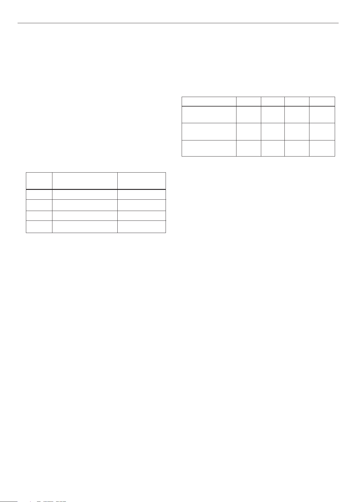
OPEN VENT SYSTEM REQUIREMENTS - FULLY PUMPED
The system should be vented directly off the boiler flow pipe, as close to the
boiler as possible. The cold feed entry should be inverted and MUST be
positioned between the pump and the vent, and not more than 150mm (6")
away from the vent connection.
There should be a minimum height - 450mm (173/4") - of open vent above
cistern water level. If this is impossible refer below.
The vertical distance between the highest point of the system and the feed/
expansion cistern water level MUST not be less than 450mm (17
3
/4").
The pump MUST be fitted on the flow side of the boiler.
A suitable pump is a domestic circulator capable of providing an 11oC (20oF)
temperature differential (e.g. Grundfos UPS 15/50 or equivalent). The vertical
distance between the pump and feed/expansion cistern MUST comply with
the pump manufacturers minimum requirements to avoid cavitation. Should
these conditions not apply, either lower the pump position or raise the cistern
above the minimum requirement specified by Ideal Stelrad Group.
Note. A cold water feed must be available back to the boiler, when all
automatic valves are in the closed position (refer to BS. 6798) and when close
coupled the feed must not be in a vertical leg.
4
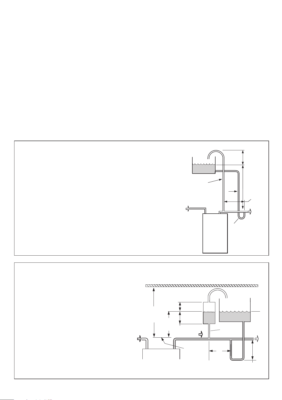
The classic HE range of boilers can be installed in low head
situations by fitting a 'surge arrester' in the expansion pipe as
shown.
The following conditions MUST be observed:
1. The surge arrester must be at least 42mm in diameter x
2. The static water level (cold) must be at least 200mm
3. The maximum practical length of 15mm cold feed pipe
Note. The pump manufacturers minimum
requirements must be complied with.
10
LOW HEAD INSTALLATIONS
150mm long, thus ensuring a MINIMUM air gap and a
MINIMUM depth of water below the static water level (cold)
of 75mm.
above the top of the horizontal flow pipe, fitted as shown.
The vent connection MUST NOT be made immediately off
the top of the boiler, as venting is made less efficient.
should be used in order to reduce the effective volume of
system water expanding into the feed/expansion cistern to
a minimum.
All dimensions in mm (in.). N.B. Imperial dimensions are approximate
Return
cla7839
450
(17
Min.
3
/4")
Minimum Requirements
75 (3)
Min.
200
(8)
Min.
Surge
arrester
75 (3) Min.
Flow
Highest
point of
flow or
return
classic HE - Installation & Servicing
Feed / expansion
cistern
22 (3/4)
Open vent
150
(6)
Max
Max. practical
Cold
water
level
To pump
length
Page 11
5
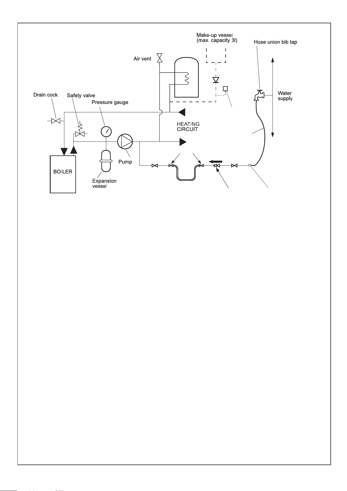
SEALED SYSTEM REQUIREMENTS
ecl6060
GENERAL
Hose unions
Temporary hose
(disconnect
after filling)
Non-return
valve
Automatic
air vent
Hosepipe
(disconnect
after filling)
Additional
stop valve
Double check valve
assembly
(note direction of flow)
Hose connector
Note.
The method of filling, refilling, topping up or flushing sealed
primary hot water circuits from the mains via a temporary hose
connection is only allowed if acceptable to the local water
authority.
1. General
a. The installation must comply with the requirements of
BS.6798 and BS.5449.
b. The installation should be designed to work with flow
temperatures of up to 82
o
C.
c. All components of the system, including the heat
exchanger of the indirect cylinder, must be suitable for a
working pressure of 3 bar (45 lb/in
2
) and temperature of
110oC. Care should be taken in making all connections
so that the risk of leakage is minimised.
2. Safety Valve
A spring loaded safety valve complying with the relevant
requirements of BS.6759 must be fitted in the flow pipe, as
close to the boiler as possible and with no intervening valve
or restriction. The valve should have the following features:
a. A non-adjustable pre-set lift pressure not exceeding 3
bar (45 lb./in
2
)
b. A manual testing device.
c. Provision for connection of a discharge pipe. The valve
or discharge pipe should be positioned so that the
discharge of water or steam cannot create a hazard to
the occupants of the premises or cause damage to
electrical components and wiring.
3. Pressure Gauge
A pressure gauge covering at least the range 0-4 bar (0-60
2
lb./in
) must be fitted to the system. The gauge should be
easily seen from the filling point and should preferably be
connected at the same point as the expansion vessel.
4. Expansion Vessel
a. A diaphragm type expansion vessel must be
connected at a point close to the inlet side of the pump,
the connecting pipe being not less than 15mm (
nominal) size and not incorporating valves of any sort.
b. The vessel capacity must be adequate to accept the
expansion of the system water when heated to 110oC
o
(230
F)
c. The charge pressure must not be less than the static
water head above the vessel The pressure attained in
the system when heated to 110oC (230oF) should be at
least 0.35 bar (5lb/in
2
) less than the lift pressure of the
safety valve.
For guidance on vessel sizing refer to the table in Frame
6. For further details refer to BS.5449. For IE refer to the
current edition of I.S. 813.
5. Cylinder
The cylinder must be either of the indirect coil type or a
direct cylinder fitted with an immersion calorifier which is
suitable for operating on a gauge pressure of 0.35 bar
2
(5lb./in
) in excess of the safety valve setting. Single feed
indirect cylinders are not suitable for sealed systems.
6. Make-up Water
Provision must be made for replacing water loss from the
system, either:
a. From a manually fitted make-up vessel with a readily
visible water level. The vessel should be mounted at
least 150mm (6") above the highest point of the
system and be connected through a non-return valve to
the system, fitted at least 300mm (12") below the
make-up vessel on the return side of the domestic hot
water cylinder or radiators.
b. Where access to a make-up vessel would be difficult by
pre-pressurisation of the system. Refer to 'Filling.'
1/2"
classic HE - Installation & Servicing
11
Page 12
GENERAL
6
SEALED SYSTEM REQUIREMENTS - continued
7. Mains Connection
There must be no direct connection to the mains water supply
or to the water storage tank supplying domestic water, even
through a non-return valve, without the approval of the local
water authority.
8. Filling
The system may be filled by one of the following methods:
a. Through a cistern, used for no other purposes, via a ball
valve permanently connected directly to a service pipe and
/ or a cold water distributing pipe.
The static head available from the cistern should be
adequate to provide the desired initial system design
pressure. The cold feed pipe from the cistern should include
a non-return valve and a stop valve with an automatic air
vent connected between them, the stop valve being located
between the system and the automatic air vent. The stop
valve may remain open during normal operation of the
system if automatic water make-up is required.
b. Through a self-contained unit comprising a cistern,
pressure booster pump (if required) and, if necessary, an
automatic pressure reducing valve and flow restrictor. The
cistern should be supplied through a temporary connection
from a service pipe or cold water distributing pipe.
This unit may remain permanently connected to the heating
system to provide limited automatic water make-up. Where
the temporary connection is supplied from a service pipe
or distributing pipe which also supplies other draw-off points
at a lower level then a double check valve shall be installed
upstream of the draw-off point.
c. Through a temporary hose connection from a draw-off tap
supplied from a service pipe under mains pressure. Where
the mains pressure is excessive a pressure-reducing valve
shall be used to facilitate filling.
The following fittings shall form a permanent part of the
system and shall be fitted in the order stated:
A stop valve complying with the requirements of
BS. 1010, Part 2 (the hose from the draw-off tap shall be
connected to this fitting).
A test cock.
A double check valve of an approved type.
• Thoroughly flush out the whole of the system with cold
water, without the pump in position.
• With the pump fitted, fill and vent the system until the
pressure gauge registers 1.5 bar (21.5lb/in
Examine for leaks.
• Check the operation of the safety valve by manually
raising the water pressure until the valve lifts. This should
occur within ± 0.3 bar (± 4.3lb/in
pressure.
• Release water from the system until the initial system
design pressure is reached.
• Light the boiler and heat the system to the maximum
working temperature. Examine for leaks.
• Turn off the boiler and drain the system while still hot.
• Refill and vent the system.
2.
2
).
) of the pre-set lift
Sizing procedure for expansion vessels: The volume of the expansion vessel (litres) fitted to a sealed system shall not be
less than that given by Table 6, multiplied by a factor of 0.8 (for flow temperatures of less than 88 oC).
Table 6
Safety valve setting 3.0 bar 2.5 bar 2.0 bar
Vessel charge and initial 0.5 1.0 1.5 0.5 1.0 1.5 0.5 1.0
system pressure bar bar bar bar bar bar bar bar
Total water content of system Expansion vessel volume
(litres) (litres)
25 2.1 2.7 3.9 2.3 3.3 5.9 2.8 5.0
50 4.2 5.4 7.8 4.7 6.7 11.8 5.6 10.0
75 6.3 8.2 11.7 7.0 10.0 17.7 8.4 15.0
100 8.3 10.9 15.6 9.4 13.4 23.7 11.3 20.0
125 10.4 13.6 19.5 11.7 16.7 29.6 14.1 25.0
150 12.5 16.3 23.4 14.1 20.1 35.5 16.9 30.0
175 14.6 19.1 27.3 16.4 23.4 41.4 19.7 35.0
200 16.7 21.8 31.2 18.8 26.8 47.4 22.6 40.0
225 18.7 24.5 35.1 21.1 30.1 53.3 25.4 45.0
250 20.8 27.2 39.0 23.5 33.5 59.2 28.2 50.0
275 22.9 30.0 42.9 25.8 36.8 65.1 31.0 55.0
300 25.0 32.7 46.8 28.2 40.2 71.1 33.9 60.0
Multiplying factors for
other system volumes 0.0833 0.109 0.156 0.094 0.134 0.237 0.113 0.20
12
classic HE - Installation & Servicing
Page 13
7
24
30
27
35
9
12
19
37
26
23
17
Condensate
siphon trap
Data
Plate
cla7926
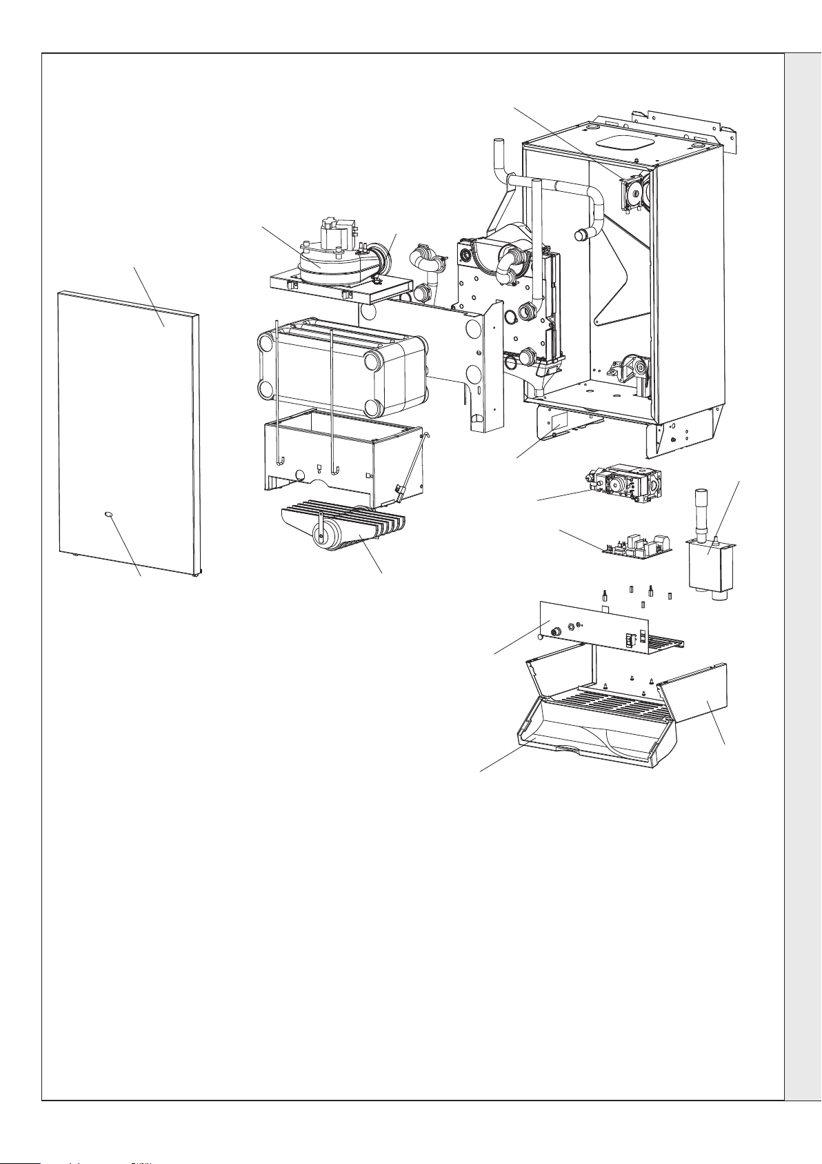
BOILER ASSEMBLY - Exploded view
INSTALLATION
INSTALLATION
LEGEND
9. Sightglass
12. Main Burner
17. Gas Valve
19. Control Box
classic HE - Installation & Servicing
23. PCB25E
24. Air pressure switch
26. Controls Casing
27. Flue Protection Thermostat
30. Fan
35. Front Panel
37. Controls Door
13
Page 14
8
ix7408
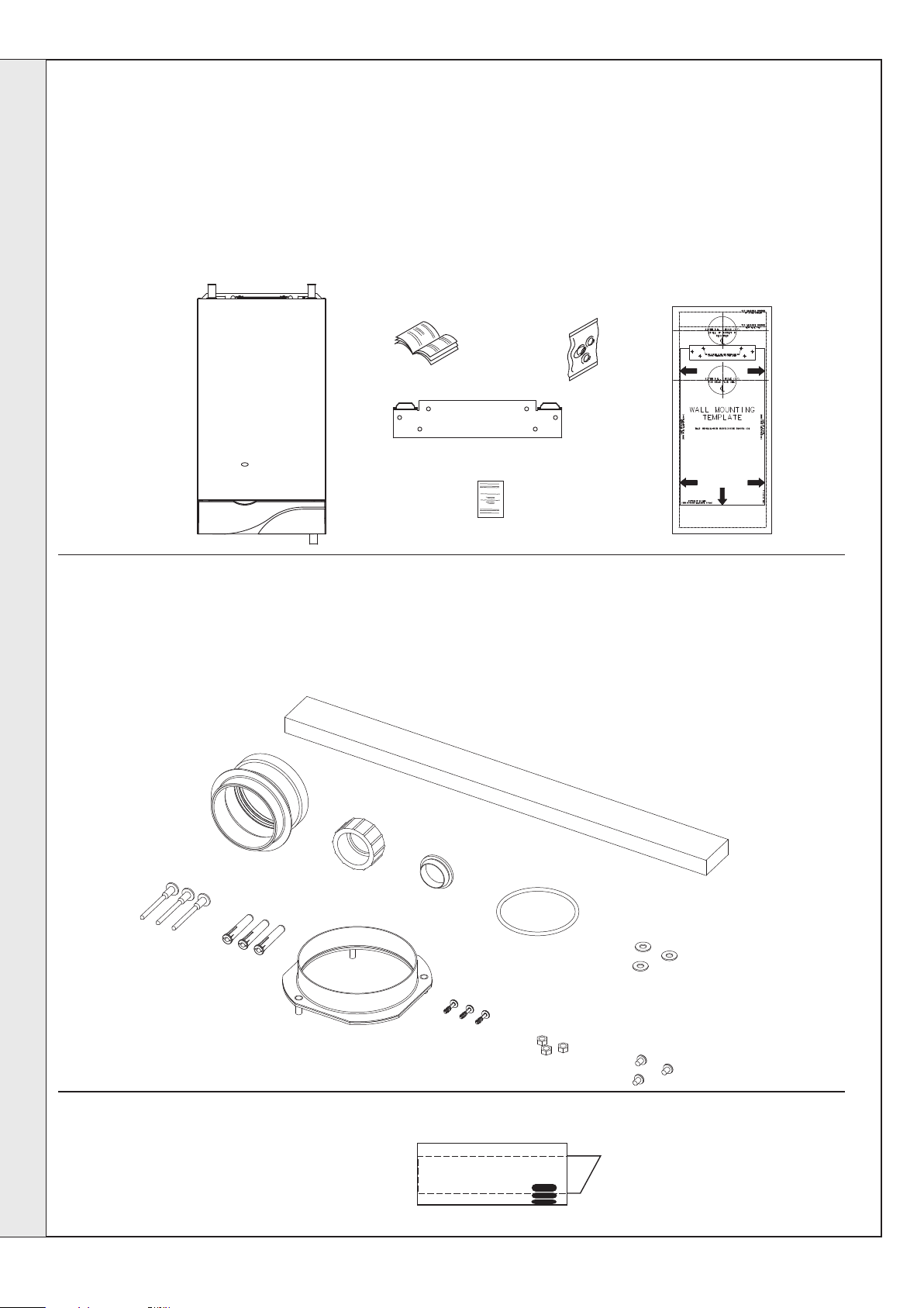
UNPACKING
The boiler is supplied fully assembled in Pack A,
together with a standard flue assembly for lengths
from 75mm (3") up to 705mm (27
from 270mm (10 5/8") up to 775mm (30
flue in Pack B.
Note. For side flue applications the optional extra
side outlet kit is required.
Unpack and check the contents.
A
3/4") rear flue and
INSTALLATION
1/2") side
INSTALLATION
Pack A Contents
A The complete boiler
B Installation & Servicing/
User's Instructions
C Hardware Pack (listed below)
B
E
F
D Wall mounting template
E Wall mounting plate
F 1 year guarantee form
D
C
Hardware Pack 1 Contents
A Pipe - Flue extension - 1 off
B Nut Siphon - 1 off
C Washer - siphon sealing - 1 off
D 'O' ring - 1 off
A
F
G
E Washer M4 Form 'C' - 3 off
F No. 14x2" slotted woodscrew - 3 off
G Wallplug - 3 off
H Sealing ring - 1 off
L
B
C
D
H
I
J
cla7643
I Screw M4 x 8 PP Taptite - 3 off
J Nut M5 hex - 3 off
K Screw No. 8 x 8 PP S/tap - 3 off
L Polyurethane foam seal - 1 off
E
cla7673
K
Pack B Contents
z Terminal grille assy. - 1 off.
14
classic HE - Installation & Servicing
Page 15
9
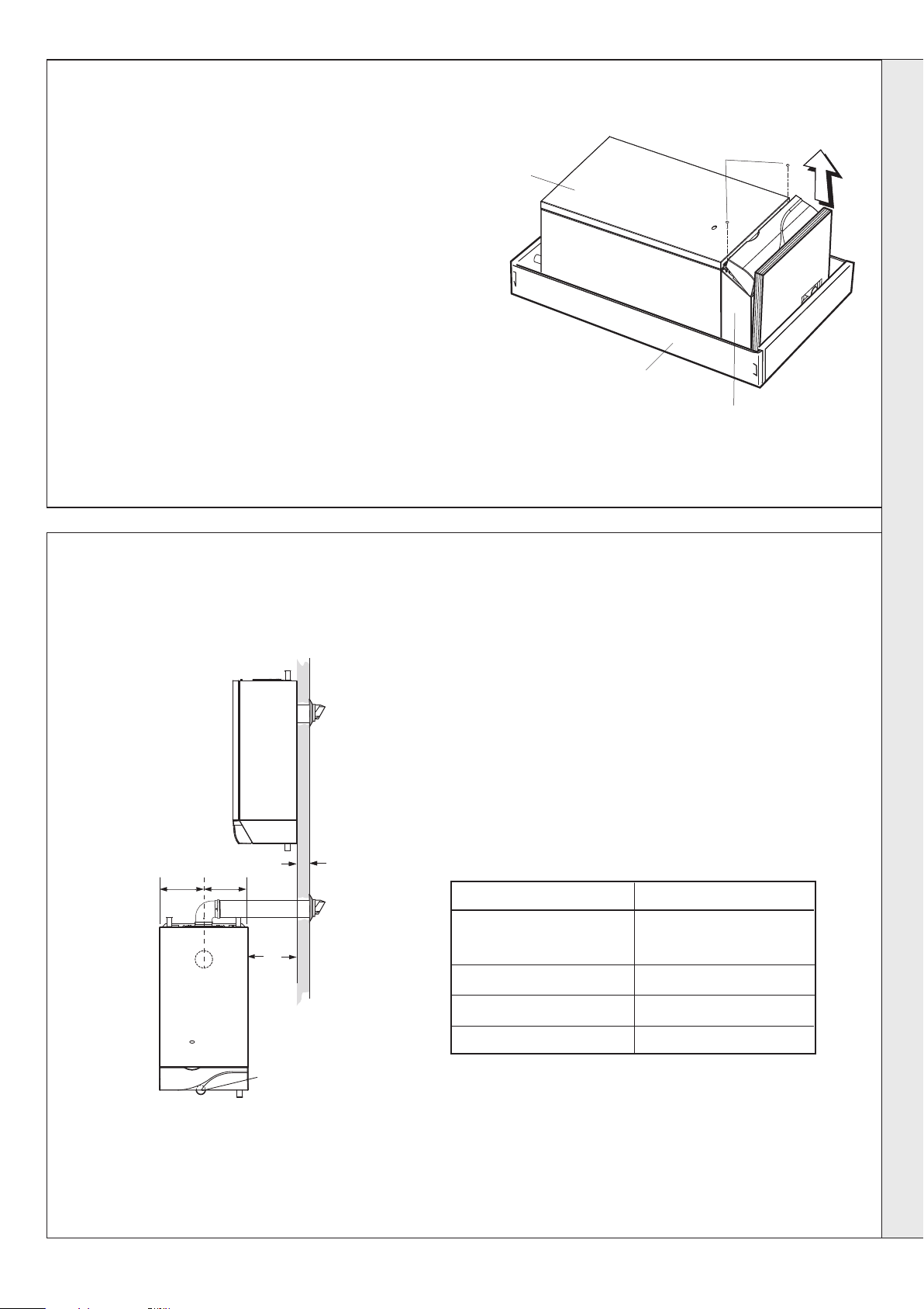
PACKAGING AND CASING REMOVAL
INSTALLATION
1. Cut straps and remove outer carton.
2. Remove packing from top of boiler (Note the wall mounting
plate is packed on this packing)
3. Leave bottom packing in place.
4. Slightly open plastic controls door to gain access to the front
panel fixing screws.
5. Remove the front casing as follows and place to one side to
avoid damage.
a. Undo the 2 front casing retaining screws (a) retaining the
casing to the back panel.
b. Lift the bottom of the front of the boiler casing up slightly then
unhook from the top.
6. Remove the hardware pack from the inside of the boiler
7. Remove the boiler from its packaging base. But do not
remove bottom packaging. The boiler may now be stood
upright on its controls support protection frame to ease
handling and installation.
8. Unpack the boiler terminal box (pack 'B') and, if applicable, the
extension flue box(es) (pack 'D').
10
DETERMINING THE FLUE LENGTH
It is MOST IMPORTANT that the boiler is installed
in a vertical position.
FLUE KITS
Pack B: supplied as standard.
Pack D: optional extension kit for side flue or vertical flue outlet.
Refer to Frame 28.
Front panel
cla7630
(a) Casing
retaining screws
INSTALLATION
Packaging base
Controls pod casing
REAR FLUE
INSTALLATION
190mm 190mm
Flue length
for rear
X
Y
SIDE FLUE
INSTALLATION
Jacking screw for
boiler alignment
Note.
A roof flue kit is available as an optional extra for
vertical flue installation, supplied with separate
fitting instructions. Refer to Frames 31 to 35.
CLA7636
Side Outlet Kit: For side outlet applications. Refer to Frame 20-
27.
1. A maximum of 3 extension ducts (plus the standard flue duct)
may be used together.
2. Flue extensions of greater than 1m (39") should be supported
with the bracket provided.
o
90
Elbow kit (equivalent flue length resistance = 1.5m)
o
45
Elbow kit (equivalent flue length resistance = 1.0m)
Flue length
From 75 up to 705 (Rear flue)
From 270 up to 775 (Side flue)
775 to 1680 B Pack 1 off + D Pack, 1 off *
1680 to 2585 B Pack 1 off + D Pack, 2 off *
2585 to 3000 B Pack 1 off + D Pack, 3 off *
B Pack Product No. 201 816
mm*
or B Pack 1 off
Accessories
* Side flue only
D Pack Product No. 201 180
Side Outlet Kit Product No. 201 866
* Measured from centre line of boiler to outside of wall.
Note. The flue duct MUST be inclined at 1.5 degrees to the
horizontal to allow condensate to drain back into the boiler and
out through the condensate drain. (Only necessary if using one or
more ‘D’ extension duct packs)
classic HE - Installation & Servicing
15
Page 16
11
cla7661
FLUE ASSEMBLY - Exploded View
1. An optional flue duct extension kit is
required for wall thicknesses greater
than 775mm (30
Frame 10.
1
/2") side flue. Refer to
INSTALLATION
1
2
3
LEGEND
1. Terminal
2. Weather seal
(optional extra)
3. Flue assembly
4. Boiler sealing ring
5. Flue extension pipe
6. 'O' ring
12
WALL MOUNTING TEMPLATE
Note. The template shows the positions of the fixing holes and the
rear flue outlet hole centre for standard installation. Care MUST be
taken to ensure the correct holes are drilled.
1. Tape template into the selected position. Ensure squareness
by hanging a plumbline as shown.
2. If fitting a side flue refer to Frame 21.
3. Mark onto the wall the following:
a. The wall mounting plate screw positions (choose one from
each group). Note. Mark the centre of the flue hole as well as
the circumference.
b. The position of the flue duct hole.
c. The jacking screw fixing hole.
4. Remove the template from the wall.
4
5
6
13
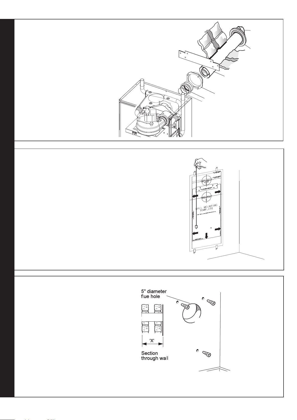
PREPARING THE WALL
IMPORTANT. Ensure that, during the cutting operation,
masonry falling outside of the building does not cause
damage or personal injury.
1. Cut the flue hole, preferably with a 125mm (5")
core boring tool, ensuring that the hole is square
to the wall. If the hole has been quite accurately cut
with a drill then making good the wall faces is not
essential as seals are provided at both ends of the
flue. However, both wall faces immediately around
the cut hole should be flat; make good if
necessary. For less accurate holes make good to
approximately 125mm (5") diameter at the two wall
faces.
2. Drill 3 holes (two for the wall mounting plate and
one for the jacking screw) with an 8mm (
masonry drill.
3. Insert the plastic plugs provided.
REAR FLUE OUTLET
16
5/16")
Note. Check all of the hole positions BEFORE drilling
classic HE - Installation & Servicing
Page 17

INSTALLATION
14
CUTTING THE FLUE - wall thicknesses of 75 to 705mm
Note. If the downward piping kit bracket is to be used, it is
essential that 30mm is added to the measured wall thickness
when marking the flue.
1. Measure and note the wall thickness X (Refer to Frame 10).
2. Mark the wall thickness onto the flue.
3. To ensure the tube is cut square, mark the flue all the way
around.
4. Position the inner flue spring to support the inner flue during the
cutting process.
5. Cut to length X, (refer to Frame 10).
6. Remove any burrs and remove the inner flue support ring.
15
FITTING THE FLUE CONNECTING RING AND THE BOILER SEALING RING TO THE FLUE
cla7841
1. Remove the two fan electrical connections, the red
pressure sensing pipe, the blue CO/CO2 sensing
pipe and the two fan fixing screws.
2. Pull the fan forward, remove and retain.
3. Remove the two fixing screws retaining the
removable top section of the aluminium
recuperator and carefully lift the recuperator top
section from the main body.
3
4. Fit the 'O' ring to the flue extension ring and fit
the flue extension ring (to be found in the
boiler hardware pack) to the rear of the
recuperator top section using the three M4 x
10 taptite screws and form C washers also to
be found in the boiler hardware pack.
Fixing
screws
Air pressure switch &
CO/CO2 sensing pipes
1
4
Electrical
connections
5. If using the flue finishing kit, push the black outer
wall seal over the outer flue duct (Refer to Frame
16) prior to fitting the flue ring. Fit the boiler sealing
ring inside the terminal 'B' pack outer flue duct.
Ensure the boiler sealing ring is fully engaged.
Ensure the notch aligns with the label on the outer
flue duct. This ensures correct alignment of the flue
terminal.
6. Drill 3 holes 3.2mm (1/8") dia. through the outer flue
duct and boiler sealing ring. Do NOT drill the inner
flue duct.
7. Insert the self-tapping screws, provided, in order to
fix the boiler sealing ring in position.
classic HE - Installation & Servicing
5
8. Stick the self-adhesive foam
strip, provided in the boiler
hardware pack, onto the flue
immediately behind the boiler
sealing ring.
cla7662
REAR FLUE OUTLET
17
Page 18

INSTALLATION
Jacking screw
cla7664
1
3
2
cla7665
3
2
16
FITTING THE FLUE ASSEMBLY AND OPTIONAL FLUE FINISHING KIT (if required)
(A) Without Optional Flue finishing Kit
1. Insert the flue assembly through the hole.
2. Ensure the notch is at the top. This will
aid the location of the studs into the boiler
back panel.
A
cla7640
17
WALL MOUNTING PLATE
1. If downward routing of pipes is required then the downward routing wall
bracket supplied in the downward piping kit should be fitted to the wall now.
2. Fix the mounting plate to the wall with the No. 14 x 50mm wood screws or to
the downward piping bracket with the M6 x 12 Hex hd screws provided.
3. Check with a spirit level that the plate is horizontal.
(B) With Optional Flue finishing Kit
1. Fit the black outer wall seal over
terminal and ensure the retaining rim is
located in the terminal depression.
2. Fit flue pipe assembly through the hole
previously cut in wall.
3. Fit wall mounting plate (Frame 17), mount
the boiler (Frame 18) and connect the flue
to the boiler (frame 19).
4. Fit outer wall sealing plate over outer wall
seal and retain with the 4 screws and wall
plugs provided.
Downward
piping
bracket
Wall mounting
bracket
36mm
B
4
2
1
cla7663
cla8181
18
MOUNTING THE BOILER
Note.
The boiler may require two men to lift it onto the wall mounting plate.
For downward routing of pipes the M5 spacer (supplied in the
downward piping kit) should now be fitted to the back of the boiler.
1. Lift the boiler onto the wall mounting plate hooks as shown.
2. Remove the bottom packaging protection.
3. Check the boiler alignment, using a spirit level, and adjust as
necessary with the jacking screw.
4. Line up the hole in the jacking screw with the hole in the wall
previously drilled and secure with the No. 14 x 50mm wood
screw.
19
CONNECTING THE FLUE TO THE BOILER
1. Locate the 3 sealing ring studs in the holes in the back panel.
Note. The sealing ring studs will locate in the back panel one way only.
This will ensure that the terminal grille is correctly aligned.
2. Secure the flue to the boiler using the three M5 nuts provided.
3. Before fitting the flue turret fill the siphon trap within the boiler by
4. Re-engage the recuperator top section flue connecting ring into the
5. Refit the fan, fan electrical connections, the red pressure sensing
REAR FLUE OUTLET
pouring a cupful of water into the recuperator outlet.
Take care to ensure that the water is only poured into the recuperator
outlet, and does not spill into the boiler casing.
plastic flue pipe and retain the top section with the two screws
previously removed (ensure the top section to main recuperator body
sealing gasket is correctly positioned in its retaining groove).
pipe and the blue CO/CO
2 sensing pipe. Refit the 2 fan fixing screws.
18
classic HE - Installation & Servicing
Page 19

INSTALLATION
cla7712
1
2
4
3
5
cla8182
3
Extended
centre line
156mm
120mm
With downward routing pipe kit
Standard Installation
20
FLUE ASSEMBLY - Exploded view
For wall thickness 270mm to 775mm
The optional side outlet kit is required
for all side flue applications.
An optional flue duct extension kit is
required for lengths (distance from the
outside wall to the relevant side of the
boiler casing) greater than 775mm (30
1/2"). Refer to Frame 10.
21
WALL MOUNTING TEMPLATE
Note. The template shows the positions for the fixing holes and the flue hole
centres for standard installation.
If the flow and return pipes are to be routed down behind the boiler the
downward routing pipe bracket, supplied with the Downward Piping Kit,
must be used. This bracket is secured to the wall and it is essential to use
only those holes as shown on the wall mounting template.
Care MUST be taken to ensure the correct holes are drilled.
1. Tape the template into the selected position.
2. Ensure squareness by hanging a plumb line as shown.
3. Extend the flue centre line onto the side wall and measure in 120mm
for standard installation or 156mm when using downward routing
pipe kit.
4. Mark onto the wall the following:
a. The 2 wall mounting plate screw positions (choose one from each
group).
b. The fixing hole for the jacking screw.
c. The position of the flue duct hole.
Note. Mark the centre of the hole as well as the circumference.
5. Remove template from the wall.
LEGEND
1. Terminal
2. External weather seal (optional)
3. Internal weather seal (optional)
4. Flue assembly
5. Side outlet kit (Optional)
SIDE FLUE OUTLET
22
PREPARING THE WALL
IMPORTANT. Ensure that, during the cutting operation,
masonry falling outside of the building does not cause
damage or personal injury.
1. Cut the flue hole, preferably with a 125mm (5") core boring
tool, ensuring that the hole is square to the wall. If the hole
has been accurately cut with a drill then making good the
inner wall face is not essential as a seal is provided (an
optional extra outer wall seal is required if necessary).
However, both wall faces immediately around the cut hole
should be flat; make good if necessary. For less accurate
holes make good to approximately 125mm (5") diameter at
the 2 wall faces.
2. Drill 3 holes, 2 for the wall mounting plate and 1 for the
jacking screw with an 8mm (5/16") masonry drill.
classic HE - Installation & Servicing
cla7666
19
Page 20

INSTALLATION
cla7667
Downward
piping
bracket
Wall mounting
bracket
cla7704
23
CUTTING THE FLUE - For flue lengths 270 to 775mm ONLY
1. Measure and note the side flue length "Y" (refer to Frame
10).
2. Add 143mm (5
the ring, cut both outer and inner tube. Ensure support
clip is in position to facilitate cutting.
3. To ensure the tube is cut square, mark the flue all the way
around.
4. Cut to length and remove any burrs.
5
/8") to dimension "Y" and measuring from
For flue lengths greater than 775mm refer to
Frames 28, 29 and 30 - Flue extension ducts.
24
FITTING THE FLUE ASSEMBLY
1. Insert the flue assembly through the hole.
2. Ensure the flue terminal is in the correct position.
cla7841
SIDE FLUE OUTLET
25
WALL MOUNTING PLATE
1. If downward routing of pipes is required then the
downward routing wall bracket supplied in the
downward piping kit should be fitted to the wall
now.
2. Fix the mounting plate to the wall with the No. 14 x
50mm wood screws or to the downward piping
bracket with the M6 x 12 Hex hd screws provided.
3. Check with a spirit level that the plate is horizontal.
20
classic HE - Installation & Servicing
Page 21

cla7672
8
Jacking screw
10
9
26
2
3
cla8184
1
A
Gasket
4
6
1
cla7844
MOUNTING THE BOILER
INSTALLATION
Note. The boiler may require two men to lift it onto the wall
mounting plate.
For downward routing of pipes the M5 spacer (supplied in
the downward piping kit) should now be fitted to the
back of the boiler.
1. The boiler is supplied for rear outlet installation.
Remove the blanking plate from the top outlet and
retain.
2. Remove the fan electrical connections, the air
pressure switch sensing pipe, the CO/CO
sensing pipe and the 2 fan fixing screws and
remove the fan. Refer to frame 15.
3. Remove the top section of the recuperator.
Refer to Frame 15. Remove the rubber fan
seal and fit this to the new recuperator top
outlet casting.
4. Fit the blanking plate and gasket to the rear
flue hole with the 3 M5 nuts provided.
5. Fit the recuperator top outlet casting c/w
rubber fan seal and retain with the two M5
screws previously removed.
6. Remove the plastic sealing plug and fit the top outlet
connecting casting and gasket, retaining with
the 2 M4 screws and 1 M5 screw
provided.
7. Refit the fan into the rubber seal
and secure with the 2 fixing
screws, replace the fan
electrical connections, air
pressure switch sensing pipe
and CO/CO
8. Lift the boiler onto the wall
mounting bracket.
9. Remove the bottom packaging
protection
10. Check the boiler alignment to the
wall using a spirit level and adjust
as necessary with the jacking
screw.
11. Line up the hole in the jacking
screw with the hole in the wall
previously drilled and secure with the
No. 14x50mm wood screw.
sensing pipe.
2
2
5
4
6
6
Electrical
connections
7
Air pressure
switch & CO/CO2
sensing pipes
SIDE FLUE OUTLET
Fixing
screws
Rubber
seal
27
CONNECTING THE FLUE TO THE BOILER
Note.
Before fitting the flue turret fill the condensate trap or siphon trap within the boiler by
pouring a cupful of water into the flue outlet A.
Take care to ensure that the water is only poured into the flue outlet, and does not
spill into the boiler casing.
1. Insert the flue assembly through the prepared hole in the wall.
2. Fit the flat self adhesive gasket supplied, to the flange of the turret, carefully
aligning the fixing holes. Locate the flue turret on the top of the boiler. CHECK
THAT THE FLUE SEAL LOCATED IN THE TOP OF THE FLUE MANIFOLD IS SECURE
AND GIVING AN EFFECTIVE SEAL.
3. Locate the flue into the turret and push to ensure full engagement.
4. Secure the flue turret on top of the boiler with the 4 screws provided.
5. Flues over 1 metre long.
Fix the flue support bracket to the wall, using the 2 wall plugs and wood screws.
classic HE - Installation & Servicing
21
Page 22

INSTALLATION
cla7675
(R or L)
28
FLUE EXTENSION DUCTS - For flue lengths greater than 705mm rear flue or 775mm side flue
Extension duct & clamp
1.0m (39") long
Wall plugs - 2 off
Washers - 2 off
mxhe7656
29
FLUE EXTENSION DUCTS - continued
Flue length Accessories Product No.
R or L
Up to 775 B Pack 1 off see Frame 10
775 to 1680 B Pack 1 off + D Pack, 1 off see Frame 10
1680 to 2585 B Pack 1 off + D Pack, 2 off see Frame 10
2585 to 3000 B Pack 1 off + D Pack, 3 off see Frame 10
Flue duct support
SIDE FLUE OUTLET
Flue extensions of greater length than 1m (39") should be
supported with the bracket provided, suitable adjusted. Refer to
Frame 28.
Clamp screws - 2 off
Support fixing screws - 2 off
30
FITTING THE KIT
1. Fit the inner flue extension duct onto
the inner flue duct.
2. Fit the outer flue extension duct onto
the outer air duct.
3. Repeat steps 1 and 2 if a second flue
extension is required.
4. Measure and mark the flue length
required onto the flue, measuring from
the ring near the terminal. (Refer to Frames
10 and 23 for the detail of flue length
calculation). Ensure the support clip is in position
to facilitate cutting.
5. To ensure a square cut, mark the flue all the way
around.
6. De-burr the cut edges.
22
1
2
Measure from
this
RING
cla7845
classic HE - Installation & Servicing
Page 23

INSTALLATION
A
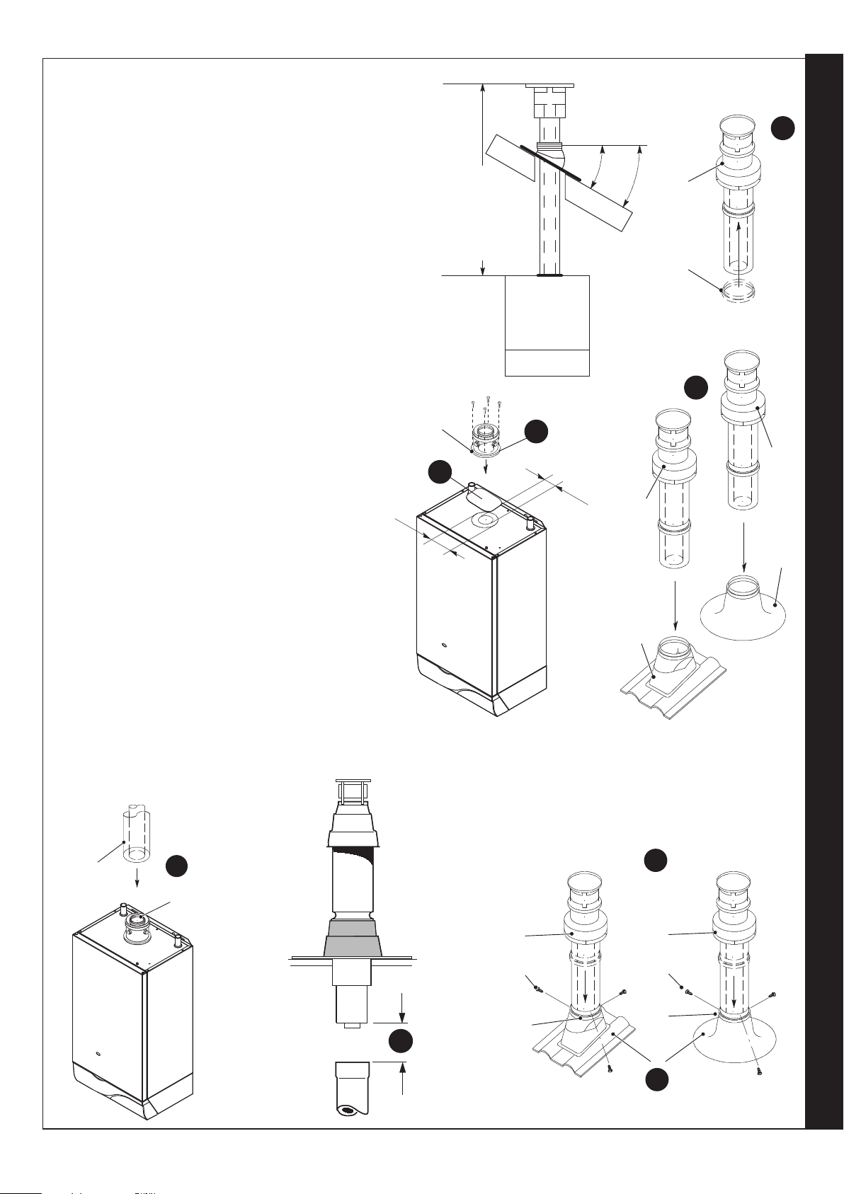
31
FITTING THE OPTIONAL ROOF FLUE KIT (Flat or Pitched)
Note.
A flat or pitched roof flashing plate (not supplied) is
required before proceeding with the installation of this
kit.
This kit is suitable for both flat and pitched roof
terminations, using a concentric flue to run vertically
from the top of the boiler and terminating above roof
level.
Connection to the top of the boiler is made using a
separately supplied vertical connector kit.
WEATHER PROOFING
Where the flue passes through the roof line an
adequate seal must be made. This is achieved by
using either:
Flat roof weather collar or Universal weather collar.
ACCESSORIES
Flue Duct Extension Kits are available for flue lengths
extending beyond 1m. These packs contain 1m
extension ducts and may be cut to the desired length.
If the offset vertical option is used an elbow Kit is
required. For a full accessories list refer to page 6,
Optional Extras and Frame 34, Flue Arrangement.
32
ROOF FLUE KIT CONTENTS / OPTIONS
A. Flue assembly with terminal
B. Flue seal collar
C. 3,5x13 screw
D. Pitched roof tile/flat roof tile
weather collar
E. Vertical connector (60/100)/
boiler vertical conversion kit
F. Roof flue extension duct kit
(60/100)
o
G. 90
elbow kit (60/100)
H. 45o elbow kit (60/100)
H
ex7534
G
F
E
Note. Items D, E, F, G and H are not supplied with the roof flue kit.
classic HE - Installation & Servicing
D
C
B
mxhe7681
FLUE OUTLET
23
Page 24

INSTALLATION
mxhe7686
mxhe7687
33
FLUE TERMINAL POSITION
The terminal should be positioned so that products of
combustion can safely disperse at all times.
Pluming may occur at the termination so, where
possible, terminal positions where this could cause a
nuisance should be avoided.
Minimum dimensions are shown below
610 mm
min.
ex7531
610 mm
min.
ex7532
34
FLUE ARRANGEMENT
Part No. Description
HE9 HE12 HE15 HE18
n/a Maximum Flue Length (m) 4 4 4 4
201 180 Flue ext. 60/100 3 3 3 3
201 189 Terminal Vertical Roof 60/100 1 1 1 1
158 431 Weather Collar Pitched Roof 1 1 1 1
158 432 Weather Collar Flat Roof 1 1 1 1
201 182 90o Elbow Kit (60/100) 2 2 2 2
201 183 45o Elbow Kit (60/100) 2 2 2 2
201 867 Vertical Connector Kit 1 1 1 1
Terminal Position Minimum Dimension
Directly below an opening,
air brick, windows, etc. 300 mm
Below plastic / painted gutters 300 mm
Painted surface 300 mm
Below eaves or balcony 500 mm
Note.
The equivalent flue length resistance of the 90
(60/100) is 1.0m and the 45o elbow kit (60/100) is 0.75m.
FLUE OUTLET
24
o
elbow kit
classic HE - Installation & Servicing
Page 25
INSTALLATION
A
A
Ø
60
Ø
100
E
5
3
cla7731
7470
A
D
A
D
2
35
ASSEMBLING THE ROOF FLUE KIT
Determine the correct height that the flue should terminate
above the roof. If after calculating or measuring the overall flue
height from the top of the boiler, it is necessary to cut both pipes
of assembly A, then ensure they are cut equally leaving the inner
flue tube longer than the outer air tube as supplied. (Refer to No.
7 below)
Ensure the cut pipe ends are free from any burrs.
1. Ensure the flue seal collar B is located onto the flue
assembly A.
2. Position the roof flashing plate D (supplied separately) over
the hole cut in the roof and insert flue assembly A from the
roof end.
3. Remove the casing top blanking plate and gasket and refit to
the boiler rear flue hole.
MAX LENGTH
(for all models)
4m
MIN LENGTH
(for all models)
1m
o
min 16
1
o
max 41
B
7469
4. Fit the boiler vertical conversion kit (to be found in the vertical
connector kit). Refer to Frame 26 No's 2 to 7.
5. Push fit the vertical connector E (supplied separately)
into the boiler flue connection and retain with the four
securing screws provided.
6. "Push" fit extension duct F (if required (supplied
separately)) and the roof flue kit assembly A into the
vertical connector E.
7. If the last extension duct requires cutting,
measure the distance (outer ducts) between the
duct and the terminal and add 100 mm to this
dimension. This gives the length of the last
extension duct.
Note. Check the position of the inner flue duct
relative to the outer duct on the assembled
extension duct(s) and ensure the terminal flue duct
is cut longer than the air duct to ensure
engagement in the final flue duct seal.
8. Slide down and position the flue seal collar B over
the roof plate D and secure it with the 3 screws C to
the flue assembly A.
9. Finally ensure the roof flashing plate D is correctly sealed to
the roof.
cla7927
F
6
E
classic HE - Installation & Servicing
cla7732
mxhe7688
8
A
C
B
C
B
7
D
cla7770
9
FLUE OUTLET
25
Page 26

INSTALLATION
cla7644
Front View
Side View
70mm (2 3/4")
38mm (1
1
/2")
Condensate
siphon drain
BOILER
cla7771
75mm trap
Sink constitutes
air break
DRAIN
Ground Level
Open end of pipe
direct into gulley
below grating but
above water level
cla9252
75mm trap
DRAIN
Sink
Ground Level
Open end of pipe
direct into gulley
below grating but
above water level
Air Break
36
GAS CONNECTION
Refer to 'Gas Supply ', page 8.
Refer to Frame 2 for gas inlet service dimensions.
A minimum pressure of 20 mbar MUST be available at the boiler inlet
with the boiler operating. The main gas cock is on the left hand side of
the gas control valve, as shown. To facilitate connection the gas cock
may be removed from the gas control valve.
38
CONDENSATE DRAIN
Refer also to the British Gas document: 'Guidance Notes for the
Installation of Domestic Gas Condensing Boilers' (1989).
INSTALLATION
The boiler comes with a built in condensate siphon trap. The boiler
condensate drain must be connected to a drainage point, preferably within
the building. This condensate drainage should be run in standard
21.5mm overflow pipe. Connection to the boiler is made by fitting the
siphon nut and sealing washer to the threaded siphon outlet.
Ensure that the condensate siphon is full of water before commissioning
the boiler. Refer to Frames 19 and 27.
The routing of the drain must be made to allow a minimum fall of 1 in 20
away from the boiler, throughout its length.
The drainage pipework must be arranged so that obstruction (e.g. through
freezing) of external drainage pipes does not give rise to spillage within
the dwelling.
37
WATER CONNECTIONS
1. Remove the plastic plugs from the flow and
return pipes.
2. Make all water connections and check for
water soundness.
IMPORTANT.
If excessive external pipework cannot be avoided a condensate removal pump (available as an option) and insulation are
recommended to prevent possible freezing.
All pipework and fittings in the condensate drain system must be made of plastic. No other materials may be used.
The drain outlet on the boiler is standard 21.5mm overflow pipe. This size must not be reduced in any part of its length.
39
CONDENSATE PIPE TERMINATION CONFIGURATIONS
Note. ALL EXTERNAL PIPE RUNS MUST BE INSULATED OR UPSIZED TO 32MM - MAXIMUM LENGTH 3M EXTERNAL
1. INTERNAL TO SINK WASTE
UPSTREAM OF SINK WASTE
TRAP
2. INTERNAL TO SINK WASTE
DOWNSTREAM OF SINK
WASTE TRAP (PREFERRED
METHOD)
26
continued . . . .
classic HE - Installation & Servicing
Page 27

INSTALLATION
BOILER
External
wall
Ground Level
Termination
to Soak away
cla7774
minimum
500mm
40
CONDENSATE PIPE TERMINATION CONFIGURATIONS . . . continued
3. INTERNAL CONNECTION TO SOIL AND VENT STACK
Termination into a down pipe can take place providing it can be
confirmed that the down pipe is part of a combined waste and rain
water system.
* Make connection to SVP using a solvent welded saddle.
BOILER
Air Break
cla9253
INSTALLATION
4. TERMINATION TO SOAK AWAY
5. TERMINATION TO DRAIN / GULLEY
External
wall
classic HE - Installation & Servicing
BOILER
cla7775
Open end of pipe
direct into gulley
below grating but
above water level
Ground Level
DRAIN
27
Page 28

Limit
thermostat
O/heat thermostat
Thermostat sensor
L
br
br
L
On/Off switch
ALL EARTHS must be connected
(Not all earths are shown for clarity)
Air pressure
switch
Flue protection
thermostat
cla7856
Combined spark &
sensing electrode
Potentiometer
L
NTC
NC
N
C
NO
P.C.B. 25
GV 1
GV 2
FAN
E
Main gas
Pilot gas
Fan
b
b
Connect
to
gy
bk
br
or
pk
w
y/g
N
bk
bk
NO
NC
com
bk
bk
r
r
y
v
41
ELECTRICAL CONNECTIONS
WARNING. The appliance must be efficiently earthed.
A mains supply of 230 V ~ 50 Hz is required.
All external controls and wiring must be suitable for mains
voltage. Wiring should be in 3-core PVC insulated & sheathed
cable, not less than 0.75mm
16 Wiring Regulations and local regulations. For IE reference
should be made to the current ETCI rules for electrical
installations.
Connection must be made in a way that allows complete
isolation of the electrical supply - such as a double pole
switch, having a 3mm (1/8") contact separation in both poles
or a plug and socket, serving only the boiler and system
controls. The means of isolation must be accessible to the
INSTALLATION
user after installation.
1. Remove controls pod by slackening front fixing screws
and pull pod forward (may find it easier to remove the
controls pod door).
2. Remove the control box securing screws. Swing the
box down into the servicing position. Refer to Frame 49.
2
(24 x 0.2mm) to BS. 6500 Table
INSTALLATION
3. Route the mains cable into the box from the RHS of the
boiler.
4. Connect the live, neutral and earth wires into the terminal
strip as shown.
5. Secure the mains lead with the cable clamp.
6. On completion of all wiring connections, relocate the control
box and secure.
cla7738
cla7923
Flow wiring diagram
LEGEND
b blue
bk black
br brown
gy grey
or orange
42
EXTERNAL CONTROLS
External wiring must be in accordance with the current I.E.E. (BS
7671) Wiring Regulations. For Ireland reference should be made
to the current ETCI rules for electrical installations.
The wiring diagrams illustrated in Frames 43-46 cover the
systems most likely to be fitted to this appliance.
For wiring external controls to the classic HE boiler, reference
should be made to the system wiring diagrams supplied by the
relevant manufacturer, in conjunction with the wiring diagrams
shown in Frames 43-46.
Difficulty in wiring should not arise, providing the following
directions are observed:
1. Controls that switch the system on or off, e.g. a time switch,
must be wired, in series, in the live mains lead to the boiler.
2. Controls that override an on/off control, e.g. frost thermostat,
28
1
2
pk pink
r red
v violet
w white
y/g yellow/green
3. If a proprietary system is used, follow the instructions
4. System designs featuring controls or wiring
Advice on required modifications to the wiring may be
obtained from the component manufacturers.
Notes.
1. Connection between a frost thermostat and the time
2. A frost thermostat should be sited in a cool place in the
must be wired into the mains lead, in parallel, with the
control(s) to be overridden. Refer to Frame 46.
supplied by the manufacturer.
arrangements which allow the boiler to fire when there is
no pump circulation taking place should not be fitted.
control should be made without disturbing other wiring.
house, but where it can sense heat from the system.
classic HE - Installation & Servicing
Page 29
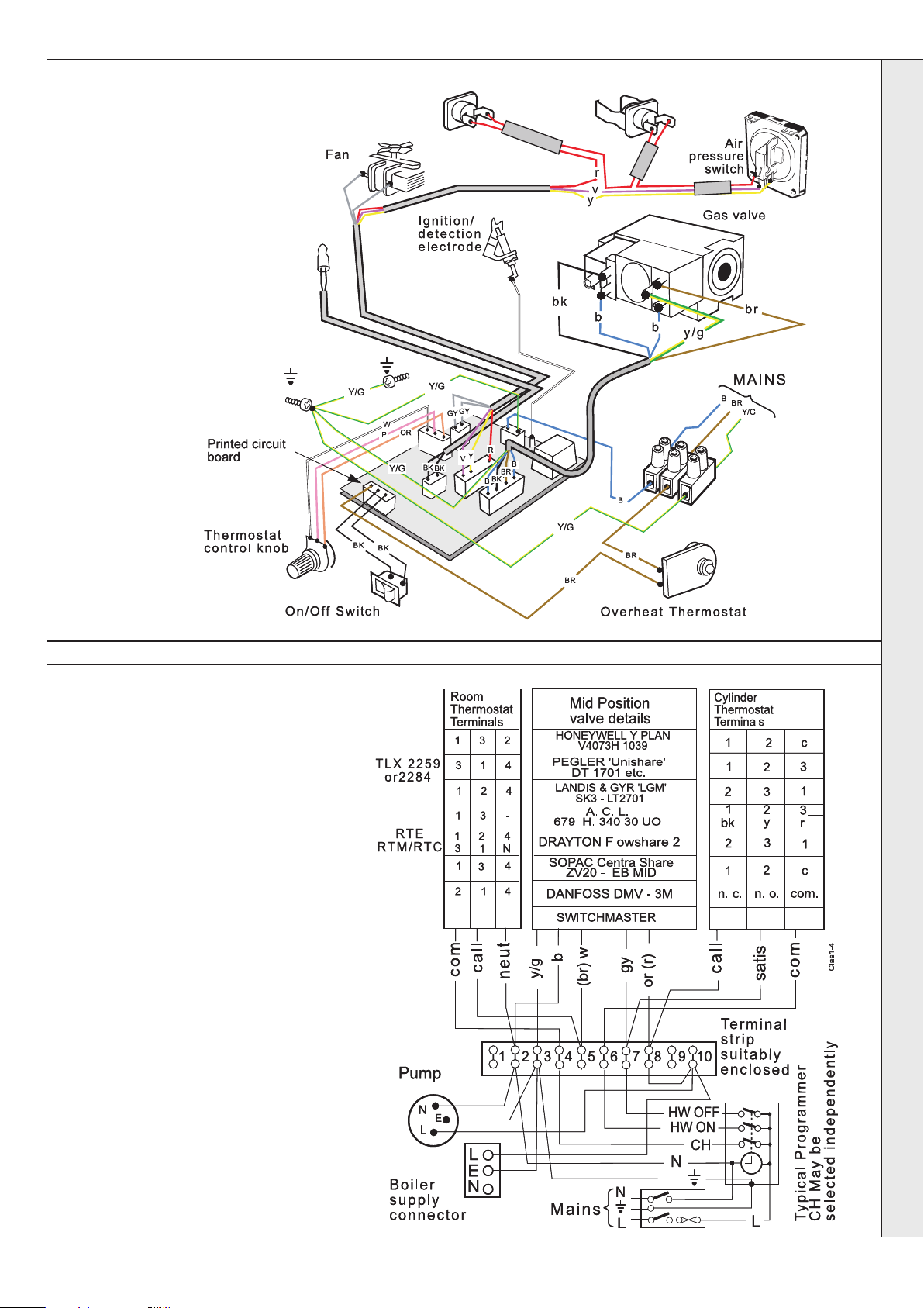
43
PICTORIAL WIRING
LEGEND
b-blue
bk - black
br - brown
gy - grey
or - orange
pk - pink
r-red
v-violet
w-white
y-yellow
y/g - yellow/green
Thermostat
sensor
INSTALLATION
Flue protection
thermostat
Limit
thermostat
INSTALLATION
cla7677
44
MID POSITION VALVE
Notes.
1. Some earth wires are omitted for
clarity. Ensure proper earth continuity
when wiring.
2. Numbering of terminals on
thermostats is specific to the
manufacturer.
3. This is a fully controlled system - set
the boiler thermostat to maximum.
4. Switchmaster 'Midi' is similar in
operation but the wiring differs slightly
- see the manufacturer's literature.
LEGEND
b-blue
bk - black
br - brown
gy - grey
or - orange
pk - pink
r-red
v-violet
w-white
y-yellow
y/g - yellow/green
Pumped only
classic HE - Installation & Servicing
29
Page 30

45
TWO SPRING CLOSED VALVE
Notes.
1. Some earth wires are omitted for
clarity. Ensure proper earth continuity
when wiring.
2. Numbering of terminals on
thermostats is specific to the
manufacturer.
3. This is a fully controlled system - set
the boiler thermostat to maximum.
INSTALLATION
4. Switchmaster valve has grey and
orange auxiliary switch leads but the
grey wire must be connected to the
live supply.
INSTALLATION
Pumped only
LEGEND
b blue
bk black
br brown
r red
y yellow
w white
46
FROST PROTECTION
Central heating systems fitted wholly inside the house do not
normally require frost protection as the house acts as a
'storage heater' and can normally be left at least 24 hrs. without
frost damage. However, if parts of the pipework run outside
the house or if the boiler will be left off for more than a day or
so, then a frost thermostat should be wired into the system.
This is usually done at the programmer, in which case the
programme selector switches are set to OFF and all other
controls MUST be left in the running position.
The frost thermostat should be sited in a cold place but where
it can sense heat from the system.
Wiring should be as shown, with minimal disturbance to other
wiring of the programmer.
gy grey
y/g yellow/green
or orange
v violet
pk pink
Designation of the terminals will vary but the programmer and
thermostat manufacturer's leaflets will give full details.
If a boiler is installed in a garage it may be necessary to fit a
pipe thermostat.
Diagram A shows a double pole frost thermostat, which should
suffice for all systems which do not use the OFF terminals of
the programmer.
Diagram B shows a 'change-over' frost 'stat', which will cover
most systems which do use CH OFF. If, however, on such a
system the HW pipework is in an isolated part of the house, a
second frost 'stat may be used to protect it. If in doubt, ask your
installer for advice.
30
classic HE - Installation & Servicing
Page 31

INSTALLATION
47
COMMISSIONING AND TESTING
The Benchmark Log Section of this book or equivalent self certification should be completed and signed to demonstrate
compliance with Building Regulations.
A. ELECTRICAL INSTALLATION
1. Checks to ensure electrical safety should be carried
out by a competent person.
2. ALWAYS carry out preliminary electrical system
checks, i.e. earth continuity, polarity, resistance to
earth and short circuit using a suitable test meter.
B. GAS INSTALLATION
1. The whole of the gas installation, including the meter, MUST
be inspected and tested for soundness, and purged in
accordance with the recommendations of BS. 6891.
In IE refer to I.S.813:2002.
2. Purging air from the gas installation may be expedited by
loosening the union on the gas service cock on the boiler and
purging until gas is detected.
3. Retighten the union and check for gas soundness.
WARNING. Whilst effecting the required gas soundness test and purging air from the gas
installation open all windows and doors, extinguish naked lights and DO NOT SMOKE.
48
INITIAL LIGHTING
TO LIGHT THE BOILER
1. Check that all the drain cocks are closed, and any valves in
the flow and return are open.
2. Check that the gas service cock (B) is OPEN and the boiler
mains On/Off switch (H) is OFF.
3. Fitting the Boiler Casing (See diagram A, Frame 49)
Hook the top edge of the boiler front casing into the channel
on the top of the boiler assembly. Swing the bottom of the
casing down and secure with the 2 captive screws.
The casing must seat correctly and compress the sealing
strip to make an airtight joint.
Visually check the side seals but, if side clearances are
limited, then check that the top and bottom edges of the
casing are correctly located.
To gain access to the gas valve:
a. Remove the controls support casing. Release the
controls support front fixing screws 3 turns only. Remove
the pod by pulling it forward to disengage from the
keyhole slots.
b. Remove the control box securing screws and swing it
down into the servicing position. (See diagram B, Frame 49) .
4. Slacken the screw in the burner pressure test point (F) and
connect a gas pressure gauge via a flexible tube.
5. Swing the control box back into its working position.
6. Press the overheat thermostat reset button (J).
7. Switch the electricity supply ON and check that all external
controls are calling for heat.
LEGEND
A Sightglass.
B Gas service cock.
C Inlet pressure test point.
D Thermostat knob
8. Set the boiler thermostat knob (D) to position 6 and the
boiler Mains On/Off switch (H) to ON. The fan will start.
After the fan has run for a few seconds the pilot solenoid
valve should open and the intermittent spark commence,
continuing until the pilot is established. The main burner
will then cross-light smoothly. If this sequence does not
occur, refer to the Fault Finding section.
9. Test for gas soundness around ALL boiler gas
components using leak detection fluid.
10. Operate the boiler for 10 minutes to stabilise the burner
temperature.
11. The boiler is pre-set at the factory to its nominal rating. If
the burner pressure measured is incorrect it may be reset
using the following procedure. Refer to Table 2 (page 4):
a. Set the mains On/Off switch (H) to OFF.
b. Switch the electricity supply OFF.
c. Swing the control box down into the servicing position.
d. Remove the main burner adjuster cover (E).
e. Turn the adjusting screw clockwise to INCREASE the
pressure, or anticlockwise to DECREASE the
pressure.
f. Swing the control box back into its working position.
g. Switch the electricity supply ON.
h. Set the mains On/Off switch (H) to ON and check the
new setting pressure.
12. If necessary repeat steps 11a to h until the required
pressure is achieved. Record this value in the Benchmark
Commissioning Checklist.
13. Set the main On/Off (H) switch to OFF.
14. Switch the electricity supply OFF.
15. Swing the control box down into the servicing position.
16. Refit the main burner pressure adjuster cover.
17. Remove the pressure gauge and tube. Retighten the
sealing screw in the pressure test point. Ensure a gas
tight seal is made.
18. After the gas pressure checks and any adjustment
operations, the adjustment screw cover must be sealed
with a suitable paint to highlight unauthorised adjustment.
E Main burner pressure adjuster.
F Burner pressure test point.
H Boiler mains on/off switch.
J Overheat thermostat reset
button.
continued . . . . . . . . .
INSTALLATION
classic HE - Installation & Servicing
31
Page 32
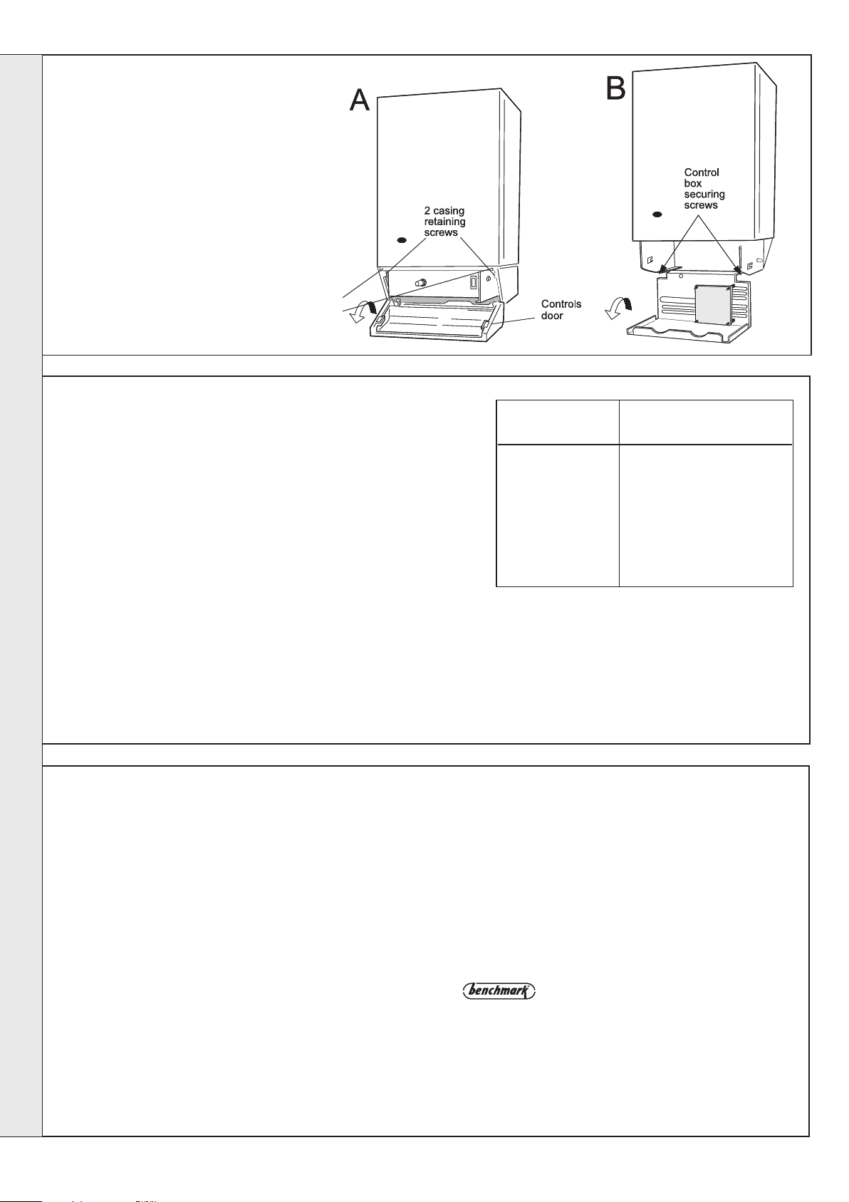
49
INITIAL LIGHTING - continued
19. Swing the control box back into
its working position and secure.
20. Refit the controls pod to the
boiler casing and tighten the 2
front fixing screws.
21. Close the pod door.
INSTALLATION
cla7679
INSTALLATION
50
GENERAL CHECKS
Make the following checks for correct operation:
1. Set the boiler thermostat knob to position 6 and operate the mains
on/off switch. Check that the main burner lights and extinguishes
in response.
2. The correct operation of ANY programmer and all other system
controls should be proved.
Operate each control separately and check that the main burner or
circulating pump, as the case may be, responds.
3. Check that the casing is sealed correctly and compressing the
sealing strip all around the casing.
4. Water Circulating System
a. With the system HOT, examine all water connections for
soundness.
b. With the system still hot, turn off the gas, water and electricity
supplies to the boiler and drain down, in order to complete the
flushing process.
c. Refill and vent the system, clear all air locks and again check for
water soundness.
d. Balance the system.
controls support
fixing screws
cla7678
Knob Setting Flow Temperature
1 54 130
2 60 140
3 66 150
4 71 160
5 77 170
6 82 180
o
C
o
F
WARNING.
The boiler MUST NOT be operated with the casing
removed.
5. Finally, set the controls to the user's requirements.
The temperatures quoted above are approximate and
vary between installations.
51
HANDING OVER
After completing the installation and commissioning of the
system the installer should hand over to the householder by
the following actions:
1. Hand the User's Instructions to the Householder and
explain his or her responsibilities under the current Gas
Safety (Installation and Use) Regulations or rules in force.
2. Draw attention to the Lighting Instruction label affixed to the
controls pod door.
3. Explain and demonstrate the lighting and shutting down
procedures.
4. The operation of the boiler and the use and adjustment of
ALL system controls should be fully explained to the
Householder, to ensure the greatest possible fuel
economy, consistent with household requirements of both
heating and hot water consumption.
Advise the User of the precautions necessary to prevent
damage to the system and to the building, in the event of
the system remaining inoperative during frosty conditions.
5. Explain the function and the use of the boiler thermostat
and external controls.
32
6. Explain the function of the boiler overheat thermostat
and emphasise that if cutout persists, the boiler should
be turned off and a registered CORGI installer
consulted. In IE contact a Competent Person.
7. Explain and demonstrate the function of time and
temperature controls, radiator valves etc., for the
economic use of the system.
8. If any programmer is fitted draw attention to the
Programmer User's Instructions and hand them to the
Householder.
9. After installation and commissioning please complete the
Commissioning Checklist before handover to
the customer. For IE, it is necessary to complete a
"Declaration of Conformity" to indicate compliance to I.S.
813:2002.
10. Stress the importance of regular servicing by a CORGI
registered installer and that a comprehensive service
should be carried out AT LEAST ONCE A YEAR. In IE
servicing work must be carried out by a Competent Person.
classic HE - Installation & Servicing
Page 33

SERVICING
cla7851
2 casing
retaining
screws
52
SERVICING SCHEDULE
To ensure the continued safe and efficient operation of the
appliance it is recommended that it is checked at regular
intervals and serviced as necessary.
The frequency of servicing will depend upon the installation
condition and usage, but should be carried out at least
annually. It is the law that any service work must be carried out
by CORGI registered installer. In IE service work must be
carried out by a Competent Person.
As the installer you may wish to undertake the service contract
yourself or alternatively offer to the customer the benefits of the
Ideal Care Scheme, details of which are outlined in the
household pack supplied with this boiler.
1. Light the boiler and carry out a pre-service check, noting
any operational faults. Operate the boiler for at least 20
minutes. Check the gas consumption.
2. Connect a suitable gas analyser to the sampling point on
the top RHS of the back panel. For correct boiler operation
the CO/CO
than 0.004 ratio. If this is the case and the gas input is at
least 90% of the nominal, then no further action need be
taken. If not, proceed to paragraph 3.
3. Clean the main burner. Refer to Frame 56.
4. Clean the heat exchanger. Refer to Frame 55.
content of the flue gas should not be greater
2
5. Clean the main and pilot injectors. Refer to Frame 56.
6 Clean the recuperator. Refer to Frame 57.
7. Remove and clean the siphon. Refer to Frame 58 and then
check the drain for blockage.
8. Remove any debris from inside the base of the casing.
9. Check that the flue terminal is unobstructed and that the
flue system is sealed correctly.
10. If the appliance has been installed in a compartment, check
that the ventilation areas are clear.
The servicing procedures are covered more fully in Frames 54
to 60 and must be carried out in sequence.
WARNING
Disconnect the electrical supply and turn off gas supply.
IMPORTANT. After completing the servicing or exchange of
components always test for gas soundness and carry out
functional checks as appropriate. Refer to Frame 48, item 18
for gas adjustment sealing.
When work is complete the casing MUST be correctly refitted,
ensuring that a good seal is made.
T
he boiler must NOT be operated if the casing is not fitted.
11. Complete the service section of the Benchmark
Commissioning Checklist.
.
53
BOILER FRONT PANEL REMOVAL
1. Open the controls pod door and release the 2 captive screws at
the bottom of the casing, then unhook the casing front panel
from the back panel and remove. Retain the front panel in a
safe place.
2. Isolate the gas supply at the service cock fitted to the boiler.
54
BURNER AND AIR BOX REMOVAL
1. Remove the screw retaining the front burner support strap
to the combustion chamber. Remove the M5 pozi situated at
the LH bottom rear of the burner and pull the burner
downwards to disengage the retention tab. Remove the
burner to a safe place for inspection and cleaning.
2. Remove the 2 control box fixing screws. Swing the box
downwards to disengage.
3. Pull the HT lead connection off the printed circuit board and
pull the lead upwards through the bottom panel grommet.
SERVICING
4. Remove the 4 screws retaining the air box/pilot assembly
to the vertical manifold and carefully remove the assembly.
5. On re-fitting the air box assembly, remove the old gasket
from the manifold and ensure the new gasket is located
correctly. Check that the joint is made gas tight. Ideal
Boilers recommend the air box fixing screws be replaced
with a torque of 4.0Nm in the number order shown on the
diagram below and be repeated to ensure even clamping.
classic HE - Installation & Servicing
2
4
3
1
cla9214
33
Page 34

SERVICING
55
CLEANING THE FAN ASSEMBLY / THE FLUEWAYS
1. Remove the air pressure switch and CO/CO2 sensing pipes.
2. Disconnect the electrical connections.
3. Remove the 2 fan fixing screws and remove the fan by pulling
forward.
1
3
2
4. Pull off the two electrical connections to the flue protection
thermostat.
4
5. Slacken the two M5 nuts on the front tie rods, releasing the
tie rods from the combustion chamber.
6. Unhook the rear collector hood tags and remove collector hood.
7. Remove the flue baffles.
8. Remove all loose deposits from the heat exchanger,
particularly between the fins, using a suitable brush.
9. Check that the fan impellor runs freely. Remove any debris
from the impellor with a soft brush.
10. Re-assemble in reverse order.
56
CLEANING THE BURNER AND PILOT ASSEMBLY
1. Brush off any deposits that may have fallen on to the
burner head (ensuring the flame ports are unobstructed)
and remove any debris that may have collected.
Note. Brushes with metallic bristles must not be used.
2. Remove the main burner injector and ensure there is no
SERVICING
blockage or damage. Clean or renew as necessary.
3. Refit the injector, using an approved jointing compound
sparingly.
4. Inspect the pilot burner and ignition / detection electrode.
Ensure that they are clean and in good condition.
57
CLEANING THE RECUPERATOR
1. Remove the 2 rubber grommets
to gain screwdriver access to
remove the side tie rods
retaining the combustion
chamber and remove the tie
rods. Also remove the two front
tie rods.
2. Remove the combustion
chamber.
3. Remove the sump rubber hose
connection.
4. Unclip the two side sump
retention clips and remove the
sump.
4
Check that:
a. The pilot burner injector is not blocked or damaged.
Refer to Frame 67 for removal details.
b. The pilot burner is clean and unobstructed.
c. The ignition / detection electrode is clean and
undamaged.
d. The ignition / detection lead is in good condition.
e. The spark gap is correct (refer to Frame 67) Clean or
renew as necessary.
Note. The pilot shield is located around the pilot assembly
bracket and is located by the electrode retaining nut.
5. Clean the sump of any debris.
6. Clean between the recuperator fins with a
suitable strip of steel.
1
6
7. Re-assemble in reverse order, ensuring
rubber grommets are replaced.
34
classic HE - Installation & Servicing
Page 35

cla7151
58
CLEANING THE SIPHON
SERVICING
4
1. Pull the heat shield forward
to remove from clips.
2. Unscrew the siphon union
connection.
3. Remove the rubber sump
connection pipe and the
blockage sensing pipe.
4. Remove the two siphon
retaining screws and remove siphon.
5. Thoroughly clean the siphon.
6. Recharge the siphon with water.
7. Re-assemble in reverse order. Ensuring the rubber sump
connection pipe and blockage sensing pipe are correctly replaced.
59
REASSEMBLY
Reassemble the boiler in the following order.
1. Refit the flue baffles.
2. Inspect the collector hood rope gasket and replace, if
necessary, ensuring that the self adhesive rope is fitted
centrally on to the lip of the collector hood / fan assembly.
The boiler efficiency will be adversely affected if incorrectly
fitted. Refit the collector hood and retain with the 2 front
and side tie rods. Tighten the nuts and screw. Ensure that
the sealing gasket is compressed.
3. Refit the fan, fan electrical connections, the thermostat
electrical connections, the red pressure sensing pipe, the
blue CO/CO
2 sensing pipe and the two fan fixing screws.
1
3
2
4. Refit the air box assembly and burner. Ensure that the burner
front fixing is refitted.
5. Refit the combustion chamber, (replacing the rope seal if necessary)
ensuring the two rubber sealing grommets are replaced.
6. Reconnect the gas supply and the electrical wiring. Refer to
Frames 36 & 41.
7. Check the sightglass in the boiler casing. Clean or renew as
necessary. Refer to Frame 62.
8. Check for gas soundness. Check the gas service cock and
pressure test point.
9. Refit the boiler casing (refer to Frame 49). Note that it is not
necessary to disturb the controls casing pod.
10. Close the controls pod door.
60
GAS PRESSURE ADJUSTMENT
PILOT
The pilot is factory set to maximum and no further
adjustment is possible. If, after removing and checking the
injector (as detailed in Frame 67) and ensuring that there
is an inlet pressure of 20 mbar available, the pilot does not
light then contact Ideal Stelrad Group.
Relight in accordance with 'Initial Lighting', Frame 48.
REPLACEMENT OF PARTS
61
GENERAL
When replacing any component:
1. Isolate the electricity supply.
2. Turn OFF the gas supply.
3. Remove the boiler front panel. Refer to Frame 53.
IMPORTANT. When work is complete the casing must be
correctly refitted, ensuring that a good seal is made.
62
SIGHTGLASS REPLACEMENT
SERVICING
MAIN BURNER
After any servicing, reference should be made to Table 2
which quotes details of the rated output with the related
burner setting pressure and the heat input. Any required
adjustments should be made by using the pressure
adjustment screw.
Refer to 'initial Lighting', Frame 48.
Note. In order to assist fault finding, the control box printed
circuit board is fitted with 2 indicator lights which represent the
following boiler conditions:
Neon I3. Mains electricity ON.
Neon SG1. Flashes to indicate ignition operation (stops after
detection).
The boiler MUST NOT be operated if the casing is not fitted.
1. Refer to Frame 61.
2. Unfasten the 2 nuts and washers holding the sightglass assembly to
the casing front panel.
3. When fixing the new assembly ensure that the parts are in the correct
order. The frame must have the return edge at the bottom.
4. Retighten the 2 nuts to ensure an airtight seal. Do NOT overtighten.
5. Replace the boiler front panel. Refer to Frame 49 .
classic HE - Installation & Servicing
35
Page 36

SERVICING
63
OVERHEAT THERMOSTAT REPLACEMENT
1. Refer to Frame 61.
2. Remove the control box fixing screws.
3. Swing the control box down into the servicing position.
64
THERMOSTAT CONTROL, THERMISTOR SENSOR LEAD & ON/OFF SWITCH
4. Pull off the electrical connections at the thermostat. Remove
the backnut retaining the thermostat to the casing. Withdraw
the thermostat phial from the heat exchanger pocket and
unclip from the casing.
5. Fit the new thermostat and reassemble in reverse order.
6. Check the operation of the boiler.
cla7849
REPLACEMENT
cla7742
Refer also to Frame 61.
A. Remove the control box fixing screws
B. Swing the control box down into the servicing position.
Thermostat control
1. Pull the knob off the shaft.
2. Remove the backnut securing the thermostat control to the control
box.
SERVICING
3. Pull off the Molex connector from the printed circuit board.
4. Replace and reassemble in reverse order.
Thermistor sensor lead
5. Pull the sensor lead connector off the printed circuit board
and cut the cable strap
securing the thermistor
harness to the bottom panel
of the control box (if fitted) and
remove the strap.
6. Remove the sensor from the
heat exchanger pocket and
unclip from the casing.
7. Remove the strain relief bush
from the back panel base.
8. Remove the sensor lead
through the grommet in the
control box.
9. Replace and reassemble in
reverse order, ensuring the
new cable strap is fitted and
securing the thermistor
harness.
On/off switch
10. Disconnect the electrical connectors
from the rear of the switch.
11. Press in the 2 side retaining clips and remove the
switch.
12. Reassemble in reverse order.
36
classic HE - Installation & Servicing
Page 37

SERVICING
65
LIMIT THERMOSTAT REPLACEMENT
1. Refer to Frame 61.
2. Remove the limit thermostat assembly from the
boiler flow pipe.
3. Disconnect the electrical connectors
4. Clip new thermostat onto flow pipe
5. Reassemble in reverse order.
NOTE. UNDER NO CIRCUMSTANCES REFIT THE
LIMIT THERMOSTAT ONTO THE RETURN PIPE
66
FLUE PROTECTION THERMOSTAT REPLACEMENT
1. Refer to Frame 61.
2. Pull off the two electrical connections.
3. Remove the two nuts retaining the flue protection
thermostat.
4. Replace the thermostat and re-assemble in reverse
order
Return pipe
Flow pipe
2
3
2
67
PILOT BURNER REPLACEMENT
1. Refer to Frame 61.
2. Remove the burner and air box assembly. Refer to Frame
54.
3. Remove the electrode retaining nut and remove the pilot
shield and electrode.
3
SERVICING
6. Replace the electrode and pilot shield, retaining
both with the electrode nut. Check the spark gap.
7. Reassemble in reverse order.
4. Unscrew the central pilot fixing screw and lift the pilot clear
of the pilot injector. The pilot injector may now be unscrewed
if required.
5. Replace the pilot burner (injector if necessary) and retain
with the M4 screw previously removed. Ensure the copper
sealing washer is replaced when refitting the pilot injector.
classic HE - Installation & Servicing
8. Check the operation of the boiler.
9. The pilot is factory set to maximum and no further
adjustment is possible. Ensure there is an inlet
pressure of 20 mbar available. Also check burner
ignition and cross-lighting.
37
Page 38

SERVICING
68
IGNITION ELECTRODE AND LEAD REPLACEMENT
1. Refer to Frame 61.
2. Remove the burner and air box assembly. Refer to Frame 54.
3. Remove the electrode retaining nut.
4. Remove the pilot shield.
5. Remove the ignition electrode and integral lead.
6. Refit the new electrode and lead in reverse order.
Ensure that the pilot shield is replaced.
7. Check the spark gap. Refer to Frame 67.
8. Reassemble in reverse order.
9. Check the operation of the boiler.
69
MAIN BURNER AND MAIN BURNER INJECTOR REPLACEMENT
1. Refer to Frame 61.
2. Remove the screw retaining the front
burner support strap to the combustion
chamber.
3. Remove the M5 pozi screw, situated at the
left hand bottom rear of the burner. Pull
the burner downward to disengage the
retention tab and remove the burner.
SERVICING
4. At this stage the main burner injector can
be removed, checked, cleaned or
replaced as required. Ensure that a new
copper sealing washer is used.
5. Fit the new burner, ensuring that the
retention tab is correctly located in the air
box slot and reassemble in reverse order.
6. Check the burner for cross-lighting and
flame stability.
70
GAS CONTROL VALVE REPLACEMENT
1. Refer to Frame 61.
2. Remove the burner and air box assembly. Refer to
Frame 54.
3. Remove the control box fixing screws.
Swing the control box down into the servicing position.
4. Disconnect the gas control valve electrical leads.
5. Undo the gas cock union .
6. Whilst supporting the gas control valve, remove the 2
screws retaining the manifold to the back panel.
38
7. Remove the gas control / manifold assembly.
8. Remove the 4 screws retaining the manifold to the gas
control valve, and fit the manifold to the new valve. Ensure
that the new control is fitted the correct way round (an arrow
engraved on back indicates the direction of flow).
9. Transfer the gas cock union to the new gas control valve,
using an approved jointing compound.
10. Reassemble in reverse order.
11. Check the operation of the boiler.
12. Refer to Frame 48, item 18 for gas adjustment sealing.
classic HE - Installation & Servicing
Page 39

SERVICING
71
FAN REPLACEMENT
1. Refer to Frame 61.
2. Remove the two fan electrical connections, the red
pressure sensing pipe, the blue CO/CO
pipe and the two fan fixing screws.
3. Pull the fan forward, remove and retain.
4. Fit the new fan and reassemble in reverse order,
ensuring the fan leads, 2 sensing tubes and the two
fan fixing screws are reconnected.
5. Check the operation of the boiler.
72
AIR PRESSURE SWITCH (APS) REPLACEMENT
2 sensing
Fixing
screws
Air pressure switch &
CO/CO
2 sensing pipes
Electrical
connections
1. Refer to Frame 61.
2. Remove the APS fixing screw.
3. Remove the 2 sensing tubes from the APS.
4. Remove the 3 electrical connections from the APS.
5. Fit the new APS and reassemble in reverse order.
6. Check the operation of the boiler.
73
PRINTED CIRCUIT BOARD (PCB) REPLACEMENT
1. Refer to Frame 61.
2. Remove the control box fixing screws and swing the
control box down into the servicing position.
3. Disconnect the detection lead from the PCB.
4. Unplug all the Molex connectors from the PCB.
2
4
red
white
3
5. Disengage the PCB from the mounting posts and withdraw
from the control box.
6. Fit the new PCB and reassemble in reverse order.
7. Check the operation of the boiler.
Fuse.
To change the fuse, prise it out of the holder and disengage
the fuse. Refer to Frame 78 for fuse location.
red
violet
yellow
SERVICING
74
COMBUSTION CHAMBER INSULATION REPLACEMENT
1. Refer to Frame 61.
2. Remove the burner and air box assembly. Refer to
Frame 54.
3. Remove the 4 tie rods.
Note. remove rubber grommets to gain access to
side tie rod screwdriver slots.
4. Remove the combustion chamber.
5. Remove the 2 side panel retaining brackets.
6. Remove the side insulation panels.
7. Remove the front and rear insulation panels.
8. Fit the new front and rear insulation panels.
9. Fit the new side panels and retain with the
brackets and screws previously removed.
10. Reassemble in reverse order.
classic HE - Installation & Servicing
3
39
Page 40

SERVICING
75
HEAT EXCHANGER REPLACEMENT
Note. Refer to Frame 7 (Boiler assembly - Exploded view) for illustration
of the procedure detailed below.
1. Refer to Frame 61.
2. Remove the burner / air box assembly. Refer to Frame 54.
3. Drain the system.
4. Disconnect the water connections. If compression fittings are used
then cut the pipes both above and below the fittings in order to
allow the heat exchanger assembly to be removed. Remove the
heat exchanger drain plug and drain the residual water into a
suitable receptacle.
5. Remove the fan/collector hood assembly, refer to Frame 55. Pull
off the electrical connections from the overheat thermostat and
pull off the white rubber tube from the siphon blockage sensing
pipe.
6. a. Rear Flue Outlet - Remove the two screws retaining the
recuperator top section. Pull the recuperator top section to
release the flue pipe connection.
b. Side Flue Outlet - Remove the 3 screws retaining the top
outlet connection casting and remove casting. Refer to Frame
26 No. 6.
7. Remove the combustion chamber by unscrewing the 4 tie rods.
8. Remove the thermostat sensors from the pockets on the heat
exchanger by removing the M3 screws and plates.
9. Remove the condensate sump. Refer to Frame 57.
10. Slacken 3 turns only the 2 bottom heat exchanger / interpanel
retaining screws and remove the top 2 heat exchanger/interpanel
retaining screws
11. Lift the heat exchanger / interpanel assembly upward and forward
SERVICING
to disengage key hole fixings. Pull the assembly downwards to
clear the water pipes from the back panel.
Note. Take care with any residual water held in the heat exchanger/
recuperator.
12. Remove the 2 rubber sealing grommets from the top
of the back panel to facilitate fitting the new assembly.
13. Fit the new heat exchanger assembly, complete with
water pipes, and hang it on the bottom key hole slots
and screws. Refit the top 2 screws and tighten 4
screws.
14. Replace the 2 rubber sealing grommets.
15. Reassemble in reverse order.
16. Remake all water connections, ensuring that the
compression fittings (if used) are correctly refitted.
17. Fully test all functions, including water and gas
soundness.
5
76
CASING FRONT SEAL REPLACEMENT
1. Refer to Frame 61.
2. Remove the old seal from the casing front and
thoroughly clean the casing surface.
3. Fit the new self adhesive seal.
4. Replace the boiler casing front.
Reverse of
casing panel
Seal
40
classic HE - Installation & Servicing
Page 41

77
SIPHON REPLACEMENT
1. Refer to Frame 61.
2. Remove the burner. Refer to
Frame 54.
3. Pull the heat shield forward to
remove from clips.
4. Pull off the rubber sump connecting
pipe and the blockage sensing pipe.
5. Unscrew the siphon union
connection.
6. Remove the two siphon retaining
screws and remove siphon.
7. Re-fit the new siphon and gasket
and reassemble in reverse order,
ensuring the rubber sump
connecting pipe and blockage
sensing pipe are correctly
replaced.
8. Ensure the siphon is charged with
water and the heat shield is
replaced.
SERVICING
3
6
4
5
SERVICING
classic HE - Installation & Servicing
41
Page 42

Is the mains on neon 'I3' illuminated?
YES
Is there a live supply on EITHER
Is there a live supply on BOTH
Check that the boiler thermostat is
set at maximum and the mains on/off
switch is ON. Is the fan turning ?
YES
Change
Is the ignition electrode sparking?
Does the pilot light ?
Is there a gas
supply to the
boiler?
Is the pilot
injector blocked?
Ensure pilot and
main gas valve
leads are not
crossed over.
Is there a supply
voltage at pilot
gas valve?
YES
FAULT FINDING FAULT FINDING FAULT FINDING
Replace
gas valve
START
NO
terminal of overheat 'stat?
YES
terminals of overheat 'stat?
NO
Is there a supply on the fan
connector at PCB ('Molex'
marked 'FAN'?).
YES
Is there a supply at the fan?
YES
fan
NO
Rectify bad
connection
YES
NO
Does the spark
YES
stop after the
pilot is lit?
YES
Check the
polarity of the
mains supply.
NO
NO
Check all connections to PCB.
If no fault found, replace PCB
Check the
continuity of
the ignition
lead from
connector to
electrode.
Does the
spark now
cease when
gas is lit?
NO
NO
YESNO
FAULT FINDING
Check mains supply and fuses.
Check programmer and system
thermostats are all ON.
Check that boiler plug and socket
are OK and fully connected.
NO
If condensate pump kit fitted check
continuity of C-NC terminals
NO
NO
Can the overheat 'stat
be reset when the
system is cold ?
Remove the sensor
(NTC) from the PCB.
Is the fan turning ?
Has the fuse blown on PCB ?
Is there a live supply on the
violet lead to pressure switch?
Is there a live supply on the red
lead to the pressure switch?
Is there a live supply on
BOTH terminals of limit stat?
Is there a live supply on BOTH
terminals of the flue protection stat
Is there a regular spark from
tube 'SG1' on the PCB?
Is the boiler casing
correctly fitted?
Does main burner
cross-light from pilot?
Is there a supply on terminals
of main gas valve?
NO
YES
NO
NO
YES
YES
YES
NO
NO
Is the main burner
injector clear?
Replace main gas
solenoid valve
YES
YES
YES
YES
NO
YES
NO
NO
YES
NO
YES
NO
YES
YES
Check for condensate blockage
Reset the overheat 'stat. Set control
'stat to maximum. Allow the boiler to
reach temperature - if the overheat
'stat trips again, measure flow
temperature.
If above 90
If below 90oC replace overheat 'stat.
o
C replace control 'stat.
NO
Replace the overheat thermostat
Replace the sensor
Replace fuse BUT, before
attempting to start boiler, check for
short between live and neutral,
also between live and earth, on all
items plugged into PCB
Check all connections to PCB.
If no error found, replace PCB.
Check connections and leads to
pressure switch. If no fault found
change pressure switch.
Check PCB by substitution
Change limit thermostat
Reset flue protection thermostat
Change flue protection thermostat
Check gap at ignition electrode.
Check electrode and lead are
undamaged and not close to
earthed metalwork.
Check all connections to PCB.
If no fault found change PCB.
Check pressure switch sensing
pipes for blockages, bad connections
and reversed connection.
Check S trap for blockage.
Is pressure difference at switch
greater than
0.9 mbar?
YES
Change
pressure switch
NO
Change
fan
42
classic HE - Installation & Servicing
Page 43

SHORT LIST OF PARTS
The following are parts commonly required due to damage or expendability.
Their failure or absence is likely to affect safety or performance of this appliance.
The list is extracted from the British Gas List of Parts, which contains all
available spare parts.
The full list is held by British Gas, Ideal Stelrad Group distributors and
merchants.
When replacing any part on this appliance use only spare parts that you can be assured conform to the safety and performance
specification that we require. Do not use reconditioned or copy parts that have not been clearly authorised by Ideal Boilers.
Key No. GC Part No. Description Qty. Product No.
9 E83-619 Sightglass Assembly Kit 1 171 414
12 E72-529 Main Burner Kit HE9, HE12 1 171 012
13 E85-308 Main Injector Kit HE9 1 171 424
E83-624 HE12 1 171 425
E83-625 HE15 1 171 426
E83-626 HE18 1 171 427
14 E80-493 Pilot Burner Injector Kit 1 171 435
15 E87-018 Pilot Burner Head c/w Injector Kit 1 171 439
17 Gas Valve Kit 1 174 172
18 E83-635 Ignition Electrode Kit 1 171 442
19 Controls Box Kit c/w PCB 1 174 171
23 H20-882 PCB25E 1 173 799
24 Air Pressure Switch Kit 1 174 064
26 Controls Casing Kit 1 174 071
27 Flue Protection Thermostat Kit 1 174 072
30 Fan Assembly Kit HE9 1 174 065
35 Front Panel Assembly Kit 1 174 069
37 Control Door Kit 1 173 586
39 Casing Seal and Screws Kit 1 174 070
45 E83-682 Overheat Thermostat (LM7) Kit 1 171 950
59 E97-310 Limit Thermostat Kit 1 173 353
When ordering spares please quote:
1. Boiler Model
2. Appliance G.C. Number
3. Description
4. Quantity
5. Product Number
HE15, HE18 1 174 063
HE12 1 174 066
HE15 1 174 067
HE18 1 174 068
classic HE - Installation & Servicing
43
Page 44

78
12
30
35
19
9
24
17
18
23
FUSE
37
39
26
27
15
14
13
13 A
45
59
cla7850
SHORT PARTS LIST
SHORT LIST OF PARTS
44
classic HE - Installation & Servicing
Page 45
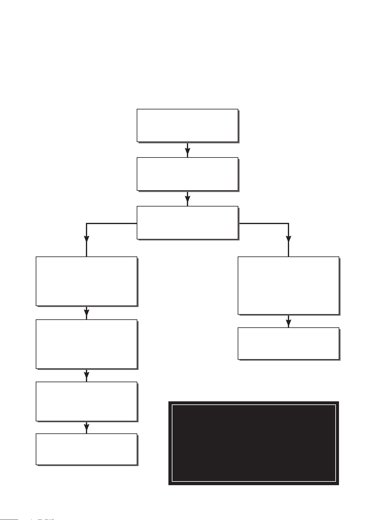
INSTALLER NOTIFICATION GUIDELINES
IT IS A REQUIREMENT OF CORGI MEMBERSHIP TO REGISTER EVERY GAS APPLIANCE
In addition a change to Building Regulations (England and Wales) requires the installer to notify
when installing a heating appliance, as from 1st April 2005.
Competent Person's
SELF CERTIFICATION SCHEME
BUILDING CONTROL
Install and commission
this appliance to
manufacturers' instructions
Complete the
Benchmark Checklist
Choose
Buildings Regulations
notification route
Contact your relevant
Local Authority
Building Control (LABC) who
will arrange an inspection
or contact a government
approved inspector
LABC will record the data
and will issue a
certificate of compliance
If you notify via CORGI Scheme,
CORGI will then notify the
relevant Local Authority Building
Control (LABC) scheme
on members behalf
Scheme members only:
Call CORGI on 0870 88 88 777
or log onto:
www.corgi-notify.com
within 10 days
You must ensure that the
notification number
issued by CORGI is written
onto the Benchmark Checklist
CORGI will record the data and
will send a certificate of
compliance to the property
IT IS A CONDITION OF THE
MANUFACTURERS WARRANTY
THAT THE BENCHMARK
COMMISSIONING CHECKLIST IS
FULLY COMPLETED AND LEFT
WITH THE APPLIANCE
classic HE - Installation & Servicing
45
Page 46

BENCHMARK No.
COLLECTIVE MARK
GAS BOILER COMMISSIONING CHECKLIST
BOILER SERIAL No. NOTIFICATION No.
CONTROLS
TIME & TEMPERATURE CONTROL TO HEATING ROOM T/STAT & PROGRAMMER/TIMER PROGRAMMABLE ROOMSTAT
TIME & TEMPERATURE CONTROL TO HOT WATER CYLINDER T/STAT & PROGRAMMER/TIMER
HEATING ZONE VALVES FITTED NOT REQUIRED
HOT WATER ZONE VALVES FITTED NOT REQUIRED
THERMOSTATIC RADIATOR VALVES FITTED
AUTOMATIC BYPASS TO SYSTEM FITTED NOT REQUIRED
To comply with the Building Regulations, each section must have a tick in one or other of the boxes
COMBI BOILER
FOR ALL BOILERS CONFIRM THE FOLLOWING
THE SYSTEM HAS BEEN FLUSHED IN ACCORDANCE WITH THE BOILER MANUFACTURERÕS INSTRUCTIONS?
THE SYSTEM CLEANER USED
THE INHIBITOR USED
FOR THE CENTRAL HEATING MODE, MEASURE & RECORD
GAS RATE ft3/hr
BURNER OPERATING PRESSURE (IF APPLICABLE) mbar
CENTRAL HEATING FLOW TEMPERATURE
CENTRAL HEATING RETURN TEMPERATURE
m3/hr
N/A
o
C
o
C
FOR COMBINATION BOILERS ONLY
HAS A WATER SCALE REDUCER BEEN FITTED? YES NO
WHAT TYPE OF SCALE REDUCER HAS BEEN FITTED?
FOR THE DOMESTIC HOT WATER MODE, MEASURE & RECORD
GAS RATE ft3/hr
MAXIMUM BURNER OPERATING PRESSURE (IF APPLICABLE) mbar
COLD WATER INLET TEMPERATURE
HOT WATER OUTLET TEMPERATURE
WATER FLOW RATE
m
N/A
3
/hr
FOR CONDENSING BOILERS ONLY CONFIRM THE FOLLOWING
THE CONDENSATE DRAIN HAS BEEN INSTALLED IN ACCORDANCE WITH
THE MANUFACTURER'S INSTRUCTIONS? YES
FOR ALL INSTALLATIONS CONFIRM THE FOLLOWING
THE HEATING AND HOT WATER SYSTEM COMPLIES
WITH CURRENT BUILDING REGULA
THE APPLIANCE AND ASSOCIATED EQUIPMENT HAS BEEN INSTALLED AND COMMISSIONED
IN ACCORDANCE WITH THE MANUFACTURER'S INSTRUCTIONS
IF REQUIRED BY
THE MANUFACTURER, HAVE YOU RECORDED A CO/CO
THE OPERATION OF THE APPLIANCE AND SYSTEM
CONTROLS HAVE BEEN DEMONSTRATED TO THE CUSTOMER
THE MANUFACTURER'S LITERATURE HAS BEEN LEFT WITH THE CUSTOMER
TIONS
TIO READING? N/A YES CO/CO
2
RA
2
o
C
o
C
lts/min
TIO
RA
COMMISSIONING ENG'S NAME
PRINT CORGI ID No.
SIGN DATE
Page 47

SERVICE INTERVAL RECORD
It is recommended that your heating system is serviced regularly
and that you complete the appropriate Service Interval Record Below.
Service Provider. Before completing the appropriate Service Interval Record below, please ensure you have carried out the service
as described in the boiler manufacturer's instructions. Always use the manufacturer's specified spare part when replacing all controls
SERVICE 1
DATE
ENGINEER NAME
COMPANY NAME
TEL No.
CORGI ID CARD SERIAL No.
COMMENTS
SIGNATURE
SERVICE 2
DATE
ENGINEER NAME
COMPANY NAME
TEL No.
CORGI ID CARD SERIAL No.
COMMENTS
SIGNATURE
SERVICE 3
DATE
ENGINEER NAME
COMPANY NAME
TEL No.
CORGI ID CARD SERIAL No.
COMMENTS
SIGNATURE
SERVICE 4
DATE
ENGINEER NAME
COMPANY NAME
TEL No.
CORGI ID CARD SERIAL No.
COMMENTS
SIGNATURE
SERVICE 5
DATE
ENGINEER NAME
COMPANY NAME
TEL No.
CORGI ID CARD SERIAL No.
COMMENTS
SIGNATURE
SERVICE 6
DATE
ENGINEER NAME
COMPANY NAME
TEL No.
CORGI ID CARD SERIAL No.
COMMENTS
SIGNATURE
SERVICE 7
DATE
ENGINEER NAME
COMPANY NAME
TEL No.
CORGI ID CARD SERIAL No.
COMMENTS
SIGNATURE
SERVICE 8
DATE
ENGINEER NAME
COMPANY NAME
TEL No.
CORGI ID CARD SERIAL No.
COMMENTS
SIGNATURE
SERVICE 9
DATE
ENGINEER NAME
COMPANY NAME
TEL No.
CORGI ID CARD SERIAL No.
COMMENTS
SIGNATURE
SERVICE 10
DATE
ENGINEER NAME
COMPANY NAME
TEL No.
CORGI ID CARD SERIAL No.
COMMENTS
SIGNATURE
Page 48

Technical Training
The Ideal Boilers Technical Training Centre offers a series
of first class training courses for domestic, commercial and
industrial heating installers, engineers and system
specifiers.
For details of courses please ring: ............ 01482 498 432
The code of practice for the installation,
commissioning & servicing of central heating systems
Ideal Boilers,
4JN. Telephone: 01482 492 251 Fax: 01482 448 858. Registration
No. London 322 137.
Ideal Stelrad Group pursues a policy of continuing improvement
in the design and performance of its products. The right is
therefore reserved to vary specification without notice.
P.O. Box 103, National Ave, Kingston upon Hull, HU5
I
deal Installer/Technical Helpline: 01482 498 663
CERTIFIED PRODUCT
Manufactured under a BS EN ISO 9001: 2000
Quality System accepted by BSI
www.idealboilers.com
Page 49

users guide
classic
Your Ideal users guide
See reverse for
classic
installation & servicing instructions
When replacing any part on this appliance use only spare parts that you can be
assured conform to the safety and performance specification that we require. Do not
use reconditioned or copy parts that have not been clearly authorised by Ideal Boilers.
HE9, HE12, HE15, HE18
Page 50

classic HE
(Natural Gas Only)
Destination Countries: GB, IE
HE9 G.C. Appliance No. 41-415-58
HE12 G.C. Appliance No. 41-415-59
HE15 G.C. Appliance No. 41-421-45
HE18 G.C. Appliance No. 41-421-46
INTRODUCTION
The classic HE is a wall mounted, room sealed, high efficiency
condensing boiler featuring full sequence automatic spark
ignition and fan assisted combustion.
Due to the very high efficiency, condensate is produced from
the flue gases and this is drained to a suitable disposal point
through the plastic waste pipe at the right lower rear of the
boiler. A condensate 'plume' will also often be visible at the flue
terminal.
SAFETY
Current Gas Safety (Installation & Use) Regulations or
rules in force.
In your own interest, and that of safety, it is the law that this
boiler must be installed by a CORGI registered installer.
In IE the installation must be carried out by a competent
person and installed in accordance with the current edition of
I.S. 813 “domestic Gas Installations”, the current Building
Regulations and reference should be made to the current ETCI
rules for electrical installation.
It is essential that the instructions in this booklet are strictly
followed, for safe and economical operation of the boiler.
ELECTRICITY SUPPLY
This appliance must be efficiently earthed.
Supply: 230 V ~ 50 Hz. The fusing should be 3A.
Connection must be made in a way that allows complete
isolation of the electrical supply such as a double pole switch
having a 3mm (1/8") contact separation in both poles, or a plug
and socket, serving only the boiler and system controls. The
means of isolation must be accessible to the user after
installation.
IMPORTANT NOTES
• This appliance must not be operated without the casing
correctly fitted and forming an adequate seal.
• If the boiler is installed in a compartment then the
compartment MUST NOT be used for storage purposes.
• The ventilation provided for the boiler during installation
MUST NOT be blocked, and a check should be made
periodically that the ventilation areas are free from any
obstruction.
• If it is known or suspected that a fault exists on the boiler
then it MUST NOT be used until the fault has been
corrected by a CORGI registered installer or in IE a
competent person.
• Under NO circumstances should any of the sealed
components on this appliance be used incorrectly or
tampered with.
• This appliance is not intended for use by persons (including
children) with reduced physical, sensory or mental
capabilities, or lack of experience and knowledge, unless
they have been given supervision or instruction concerning
use of the appliance by a person responsible for their safety.
• Children should be supervised to ensure that they do not play
with the appliance.
MINIMUM CLEARANCES
A clearance of 450mm (17 3/4") MUST be available at the front of
the boiler for servicing.
The minimum clearances given below MUST be complied with
in order to maintain the safe running of the boiler .
Above the boiler 100 mm (4")
At each side of the boiler 5 mm (
Underneath the boiler 100 mm (4")
In front of the boiler 5 mm (1/4")
1/4")
TO LIGHT THE BOILER. REFER TO FRAME 1
If a programmer is fitted, refer to separate instructions for the
programmer before continuing.
1. CHECK THAT THE ELECTRICITY SUPPLY TO THE BOILER
IS OFF.
2. Open the controls access door by hinging downwards.
3. Ensure that the gas inlet cock (D) is OPEN.
4. Press the overheat reset button (E), located as shown in
Frame 1.
5. Ensure that the mains on/off switch (C) is in the OFF position.
6. Switch ON the electricity supply to the boiler. Check that all
external controls, e.g. room thermostat etc., are ON.
7. Turn the boiler thermostat knob (B) to position 6 and the
mains on/off switch (C) to ON. After about 15 seconds the
boiler will light automatically - this can be viewed through the
sight glass (A).
Set the boiler thermostat to the desired position.
8. Close the controls access door.
In winter conditions, i.e. central heating and domestic hot water,
the thermostat should be set at position 5 or 6.
For summer conditions, i.e. domestic hot water only, the
thermostat should be set at position 3.
These settings, however, are offered for general guidance only
and other settings may be found preferable, dependent upon the
type of system installed or as recommended by the installer.
CAUTION. To avoid the possibility of injury during the installation, servicing or cleaning
of this appliance care should be taken when handling edges of sheet steel components
2
classic HE - Users
Page 51

CONTROL OF WATER TEMPERATURE
1. Adjust the boiler thermostat (B) to give the required
temperature of central heating.
2. The boiler thermostat automatically switches the main
burner OFF and ON to maintain the selected temperature.
Approximate flow temperatures for the boiler thermostat settings
are:
Knob Setting Flow Temperature
1 54 130
2 60 140
3 66 150
4 71 160
5 77 170
6 82 180
o
C
o
F
TO SHUT DOWN THE BOILER
1. For short periods
Turn the boiler on/off switch (C) to OFF.
When heating is again required, restore the switch to ON.
2. For longer periods
Turn the boiler ON/OFF switch (C) to OFF.
Switch the electricity supply to OFF.
TO RELIGHT THE BOILER
Repeat the procedure 1 - 8, detailed in 'To light the boiler'.
FROST PROTECTION
If no frost protection is provided and frost is likely during a short
absence from home, leave the heating controls at a reduced
temperature setting.
For longer periods, the entire system should be drained including the domestic water supply. If the system includes a
frost thermostat then, during cold weather, the boiler should be
turned OFF at the time switch(es) ONLY. The mains supply
should be left switched ON, with the boiler thermostat left in the
normal running position.
BOILER OVERHEAT THERMOSTAT
The boiler is fitted with a safety 'cutout' thermostat. This will shut
down the boiler in the event of overheating. Should this occur
allow the boiler to cool, press the reset button (E) then relight as
detailed in steps 1-8 in 'To light the boiler'.
If the cutout condition still persists turn off the boiler and consult
a CORGI registered installer or in IE a competent person.
CONDENSATE DRAIN
The condensate drain (F) must not be modified or blocked.
Blockage of the condensate drain, caused by debris or freezing,
can cause automatic shutdown of the boiler.
If freezing is suspected and the pipe run is accessible an
attempt may be made to free the obstruction by pouring hot
water over the exposed pipe and clearing any blockage from the
end of the pipe. If this fails to remedy the problem the
assistance of a CORGI registered installer or in Ireland a
competent person should be sought.
ESCAPE OF GAS
Should a gas leak be suspected, contact your local gas supplier
without delay.
Do NOT search for gas leaks with a naked flame.
CLEANING
For normal cleaning simply dust with a dry cloth.
To remove stubborn marks and stains, wipe with a damp cloth
and finish off with a dry cloth.
Do NOT use abrasive cleaning materials.
MAINTENANCE
The appliance should be serviced at least once a year by a
CORGI registered installer or in IE a competent person.
1
BOILER CONTROLS
View inside boiler controls area
LEGEND
A Sightglass.
B Thermostat knob.
C Mains on/off switch.
D Gas service cock
(shown in the OPEN position).
E Overheat thermostat reset button.
F Condensate Drain
All CORGI registered installers carry a CORGI ID card, and have a registration number. Both should be recorded in the Benchmark
Commissioning Checklist. You can check your installer by calling CORGI direct on 01256 372300.
Ideal Stelrad Group is a member of the Benchmark initiative and fully supports the aims of the
programme. Benchmark has been introduced to improve the standards of installation and
commissioning of central heating systems in the UK and to encourage the regular servicing of
all central heating systems to ensure safety and efficiency.
THE BENCHMARK SERVICE INTERVAL RECORD MUST BE COMPLETED AFTER EACH SERVICE
classic HE - Users
cla7646
F
3
Page 52

POINTS FOR THE BOILER USER
Note. In line with our current warranty policy we would ask that you check through the following guide to identify any
problems external to the boiler prior to requesting a service engineers visit. Should the problem be found to be other than
with the appliance we reserve the right to levy a charge for the visit, or for any pre-arranged visit where access is not gained
by the engineer.
TROUBLESHOOTING - TYPICAL NON PRODUCT FAULTS
Problem Solution
Boiler is not working for
central heating or hot water.
Boiler goes through the
ignition sequence but will not
fire for central heating or hot
water.
Boiler is operating
satisfactorily for domestic hot
water but will not operate for
central heating.
Boiler is operating
satisfactorily for central
heating but will not operate
for domestic hot water.
Boiler will not fire the pilot
light is lit but the igniter
continues to spark and the
main burner does not ignite.
Boiler cycling on and off the
fan and burner come on for
short periods but the pump
can be heard.
• Check on/off switch ( C ) is in the ‘on’ position.
• Press overheat thermostat (E) - the boiler should then relight – If the fault recurs turn off the
boiler and contact the installer.
• Check condensate pipe is not blocked or frozen. If blocked, clear blockage - if not possible to
check, contact your installer.
• Check gas supply (try at another gas appliance e.g. cooker / fire) – If no gas supply then not a
boiler fault – contact your gas supplier.
• If an external programmer is fitted check that the central heating channel is at an ‘on’ period
• Check that the room thermostat is set at the required temperature. Test the room thermostat
by turning this fully up – if this does not respond contact your installer.
• If an external programmer is fitted check that the domestic hot water channel is at an ‘on’
period.
• Check that the domestic hot water cylinder thermostat is set at the required temperature. Test
the cylinder thermostat by turning this fully up – if this does not respond contact your installer.
• This is a symptom of crossed polarity i.e. the live and neutral supply to the boiler are crossed
over. This is not a boiler fault contact your installer to correct the wiring.
• There is an air lock in the boiler or system pipework and the interrupter thermostat is shutting
down the boiler. Vent air from the radiators and ensure all thermostatic radiator valves are in
the open position. If unable to free the air lock contact your installer.
Ideal Consumer Helpline
Tel: 01482 498660
www.idealboilers.com
Ideal Stelrad Group pursues a policy of continuing improvement in the design and performance
of its products. The right is therefore reserved to vary specification without notice.
Ideal Boilers, P.O. Box 103, National Ave, Kingston Upon Hull, HU5 4JN. Tel.
01482 492251 Fax. 01482 448858. Registration No. London 322 137.
 Loading...