

Page 1

OPERATIONS & USER MANUAL
1
NOVEMBER 2016
Page 2

TABLE OF CONTENTS
1.0 INTRODUCTION TO
AUDACY® WIRELESS CONTROLS .............. 3
2.0 GATEWAY – PROXY - AUDACY SERVER
COMMUNICATIONS OVERVIEW ..............4
INSTALL ................................. 5
3.0 SYSTEM SETUP ............................... 6
3.1 MUST READ: SYSTEM INSTALLATION
GUIDELINES........................................6
3.1.1 Serial Number Device Tracking Requirement .....6
3.2 PHYSICAL INSTALLATION......................6
3.2.1 Gateway Installation .............................6
3.2.2 Luminaire Controller Installation ..................7
3.2.3 Plug Load Controller Installation..................7
3.2.4 Switch and Sensor Installation ...................8
3.2.5 Wall-Mount and Scene Switches . . . . . . . . . . . . . . . . . 8
3.3 PROXY SOFTWARE INSTALLATION ............ 9
3.4 GATEWAY SETUP ............................... 9
3.4.1 Static IP Address Setup.........................10
3.4.2 DHCP Address Setup ...........................10
3.4.3 Adding a Gateway to AudacyControls.com ......10
4.0 SETTING UP AUDACYCONTROLS.COM........11
4.1 WEB APPLICATION ............................11
4.1.1 Login to Web Application ....................... 11
4.1.2 Adding an Administrator ........................ 11
4.2 MOBILE APPLICATION .........................12
4.2.1 Login to Mobile Application .....................12
4.2.2 Adding an Administrator ........................12
5.0 CREATING ROOMS ...........................13
6.0 ADDING DEVICES INTO THE SYSTEM ........ 14
6.1 MOBILE INSTALLATION METHOD
RECOMMENDED............................ 14
6.1.1 Scanning Devices via the Audacy iOS App ...14-15
6.2 AUDACYCONTROLS.COM INSTALLATION
METHOD...................................... 16
CONFIGURE .............................17
7.0 SYSTEM CONFIGURATION................... 18
7.1 ASSOCIATING DEVICES....................... 18
7.2 ADJUSTING ROOM SETTINGS................. 19
7.3 CONFIGURING SCENES ...................... 19
CONTROL ..................................20
8.0 SYSTEM CONTROL AND OPERATION .........21
8.1 CREATING A ROOM GROUP ...................21
8.2 ADDING AUTHORIZED USERS .................21
8.3 BASIC SCHEDULING ..........................22
8.3.1 Creating a Schedule for a Given Room ..........22
8.4 ADVANCED SCHEDULING PROGRAMS ..2324
8.5 UPLOADING FLOOR PLANS...................24
8.6 ASSIGNING ROOMS TO FLOOR PLANS ....... 25
8.7 CONTROLLING LIGHTS .......................25
8.7.1 Within the Space................................25
8.7.2 From AudacyControls.com and App.............25
9.0 CONSUMPTION REPORTS ...................26
9.1 OVER TIME ...................................26
9.2 BY AREA ...................................... 26
9.3 EXPORTING CONSUMPTION DATA ...........26
9.4 BUILDING AUTOMATION INTEGRATION.......26
APPENDIX .................................. 27
A. SAFETY AND REGULATORY INFORMATION..28
B. PRE-COMMISSIONING CHECKLIST .......... 29
C. DEFAULT SETTINGS..........................30
D. DEVICE INFORMATION ...................31-32
E. LUMINAIRE CONTROLLER
REQUIREMENTS ............................33
F. LUMINAIRE CONTROLLER ONE LINE
DRAWINGS .............................34-41
G. SENSOR COVERAGE PATTERNS ..........42-46
2
H. DEVICE LAYOUT RECORD ...................47
Page 3

1.0 INTRODUCTION TO AUDACY® WIRELESS CONTROLS
The Audacy Wireless Controls system from IDEAL can bring
advanced solutions to any commercial lighting application.
Its simple installation, conguration, and operation allows
any user to achieve signicant energy savings without the
usual complications.
The Audacy Wireless Controls system brings you
tried-and-true lighting control strategies, including:
• Occupancy
• Vacancy
• Daylight Harvesting
• Scheduling
• Scene Control
• Remote System Control
• Automatic Demand Response (ADR)
The system revolves around wireless Luminaire Controllers,
wireless sensors and switches, and wireless Gateways
that can interface with Building Automation Systems using
industry-standard protocols such as BACnet, Lonworks,
and Modbus.
AUDACY SYSTEM ARCHITECTURE
The sensors and switches are completely wireless devices
and have a 25-year battery life. Sleek and stylish, they can
be placed anywhere you need coverage and are easily
added, congured, or modied.
Audacy Luminaire Controllers are capable of controlling
0-10V dimming LED drivers and uorescent ballasts, ELV or
MLV/line dimming luminaires.
Tying everything together is AudacyControls.com. Accessed
through a web browser or mobile device, you can control
your lighting network from anywhere with an Internet
connection. Controlling lights, making conguration
changes, or providing energy consumption reports are all
part of AudacyControls.com. Just like the rest of the system,
AudacyControls.com is designed to be simple, intuitive,
and user-friendly, while providing the maximum amount of
exibility and control.
3
1.0 INTRODUCTION TO AUDACY® WIRELESS CONTROLS
Page 4

2.0 GATEWAY - PROXY - AUDACY® SERVER
COMMUNICATIONS OVERVIEW
To enable the Audacy Wireless Controls system for website control and conguration or an iOS app, a proxy is required
to provide a secure connection to the Audacy Server. The proxy is a reverse type of server and runs behind the user’s
rewall. The proxy will manage requests from the Internet toward the Gateways located on the user’s internal network. It
secures, routes and manages the trafc from the Internet to the user’s internal network where the Audacy Gateways reside.
It protects the internal network from externally perpetrated attacks. The proxy will only allow the Audacy Server to access
and manage the Audacy Gateways located on the internal network.
The proxy will require the user’s rewall to allow outgoing messages on port 993 from the proxy machine’s IP address. The
connection between the proxy and the Audacy server is 2048-bit SSL encrypted. The proxy can be installed on Windows,
Linux or Mac devices.
Hardware and software requirements:
• ALWAYS ON PC or virtual machine to install proxy SW
• Windows 7 or better (2008+)
• 2 Ghz CPU
• 2 GB RAM
• 10Mbps network Interface
• Login information for proxy installation
• Extracted le from proxy download
• Gateway Installation information:
1. IP address (static or DHCP)
2. Netmask
3. IP Gateway
4. DNS addresses
Above PC must be on same network as Audacy Gateways so the proxy is able to connect to Gateways over
network. Gateways and proxy server machine must be behind the customer rewall to provide for adequate security
(recommendation: an isolated VLAN should be set up for Audacy equipment).
Open Port 993 to IP address 54.172.131.103 for outgoing connections from the IP address of the PC or virtual machine on
which the proxy is running.
4
2.0 GATEWAY – PROXY - AU DACY® SERVER COMMUNICATIONS OVERVIEW
Page 5

INSTALL
5
Page 6

3.0 SYSTEM SETUP
3.1 MUST READ: SYSTEM INSTALLATION GUIDELINES
There are a number of ways to install an Audacy® Wireless
Controls system, and covered in this User Manual is the
*RECOMMENDED* approach. The following points are
important to remember during the installation process:
1. All Audacy devices have an associated barcode.
These barcodes are located on the back of all
devices, and are used to recognize a device on
AudacyControls.com. It is important to keep
track of where these devices are installed so that
AudacyControls.com is an accurate reection of the
actual installation of the system.
2. Before electronically tracking devices, YOU MUST
INSTALL THE PROXY (FOR THE GATEWAY), SETUP
THE GATEWAY AND CREATE ROOMS (sections 3.3,
3.4 and 5.0 of this manual). The scanning feature on
the Audacy iOS app automatically adds devices into
rooms that exist. Devices cannot be added prior to
room creation.
3. The bar codes can also be entered into the system via
the scanning feature on the Audacy iOS app.
3.1.1 SERIAL NUMBER DEVICE TRACKING REQUIREMENT
It is highly recommended to keep close track of all device
barcodes. Instructions for ways to track are list here:
- Remove the 2 tear-away stickers that contain the
serial number (see image below).
- Apply these to a drawing of the space containing the
xture or a tracking sheet to identify the serial number
and its location in the room (tracking sheet available
in Appendix, p. 47).
- If these tear away labels are missing, please write
down the serial number of the Luminaire Controller in
a safe place.
- These serial numbers are required in order to have a
fully functioning Audacy Wireless Controls system.
3.2 PHYSICAL INSTALLATION
3.2.1 GATEWAY INSTALLATION
1. The Audacy Gateway has two mounting anges that
can be used to mount it to a wall or other surface
using screws. (Before installation, note and record the
Mac Address and Serial Number on the underside of
the gateway for future reference).
2. For optimal performance, the antennas should be
placed in a vertical orientation.
6
INS TALL 3.0 SYSTEM SETUP
Page 7

3.2.2 LUMINAIRE CONTROLLER INSTALLATION
Luminaire Controllers are easily installed modules that
can turn on/off and dim xtures and are available as
internal or external mount to allow for junction box or
xture installation. For maximum exibility each xture
can be controlled by a single Luminaire Controller or a
Luminaire Controller can control multiple xtures as a zone
(see Appendix p. 33 for maximum xtures per Luminaire
Controller).
3.2.3 PLUG LOAD CONTROLLER INSTALLATION
The Plug Load Controller is a 20-Amp rated wireless switch
to control power to a typical outlet. This product requires
wiring to be performed per the NEC and local codes
dictated by the AHJ.
Retro-fit Installation (for single outlet in box)
1. Remove the old device and disconnect the Line and
Neutral wires from device. Keep the ground wire
attached.
2. Disconnect the Line and Neutral wires that were
coming to the device from their pigtail connections.
3. Connect the Plug Load Controller LINE (black) and
NEUTRAL (white) wires to the pigtails that were
connected to the device that was just removed.
These wires are on the side of the device which will
face the box.
4. Re-connect the device to the SWITCHED HOT (red)
and NEUTRAL (white) coming out of the Plug Load
Controller. This side is facing out towards the device.
5. Terminate the wires to the device as required per the
device installation instructions.
6. IMPORTAN T: Position the Plug Load Controller into
the junction box so the serial number label is facing
toward the outlet.
7. Place “Controlled outlet” sticker on the face of the
outlet.
8. Or use a “Controlled Device” outlet that is properly
marked for this application.
As a reminder, keep track of serial numbers as described
in Se c t i on 3.1.1.
Refer to Appendix p. 34 for Luminaire Controller one line
drawings and p. 31 for device information.
WARNING: Before working on any circuits, verify that
Power is turned OFF to the branch circuit coming into the
outlet box being updated.
Device side wiring Plug Load Label Facing Outlet
As a reminder, keep track of serial numbers as described in Section 3.1.1.
Retro-fit Installations (for single outlet plus branch circuit run continuing from box)
1. Follow same instruction as above, but pigtail the red hot wire to the run traveling to other devices on the same circuit.
2. You may run 2 separate runs that have 1 always HOT and 1 Switched Hot if so desired to the next run on the circuit.
7
INS TALL 3.0 SYSTEM SETUP
Page 8

3.2.4 SWITCH AND SENSOR INSTALLATION
Motion Sensors and the Remote Switch require no wiring and detect occupancy/vacancy. Light Sensors also require no
wiring and are used for daylight harvesting. These devices are engineered to provide maintenance-free battery life.
1. As switches and sensors are installed remove one of
the labels with the unique serial number and attach it to
the Device Tracking Form included in the Appendix to
record the location of each device.
2. The sensor must be activated by pressing a small
button underneath the label on the back side of the
sensor.
• This can be accomplished by using a paperclip, the
screw that is included with the sensor, or similar object
to push through the label and depress the switch.
3. Find a suitable location for the sensor based on the
specications shown in the sensor coverage pattern in
the Appendix p. 42-46.
For optimal performance:
• Make sure the sensor has a line of sight to the occupant
in the space.
• Plan on a 8’ radius of coverage when mounted on a 9’
ceiling (extended coverage for high bay or wide range
versions).
4. Mount the cradle in the desired location via screws,
ceiling tile wire (included) or double-sided tape.
5. Insert the sensor into the cradle.
• If desired, the sensor can be secured to the cradle
by aligning the holes on the sensor and cradle and
inserting the screw provided through the cradle and
Note: When the sensor hasn’t detected motion for the time specified in “vacancy timeout” the lights will flash 60 seconds prior
to turning off as a warning.
As a reminder, keep track of serial numbers as described in Section 3.1.1.
into the sensor.
3.2.5 WALL-MOUNT AND SCENE SWITCHES
Wall–Mount and Scene Switches t into decorator-style faceplates and can
be used to replace an existing switch.
1. As switches are installed
remove one of the labels with
the unique serial number
and attach it to the Device
Tracking Form included in
the Appendix to record the
location of each device.
2. The switch must be activated
by pressing a small button
recessed on the back side of
the switch.
• This can be accomplished
using a paper clip or similar
object.
As a reminder, keep track of serial numbers as described in Section 3.1.1.
8
INS TALL 3.0 SYSTEM SETUP
3. Remove existing switch and
properly terminate any preexisting wires.
4. Use screws to secure the
ush-mounted switch to the
electrical box.
5. Cover with a decorator style
faceplate.
Page 9

3.3 PROXY SOFTWARE INSTALLATION
AudacyControls.com utilizes a software application known as a proxy that resides behind the client rewall on a host server.
The host server is a PC or server dedicated to running the proxy software.
To install the proxy on the host server:
1. Verify that you have obtained the Admin login
information from Audacy® Customer Support; if you
have not received this, contact Audacy Customer
Support at 800-273-9989.
2. From the host server login to AudacyControls.com
with your Admin account.
3. Select the appropriate Audacy service package for
your host server.
4. Once the compressed le has been downloaded, be
sure to extract/unzip the “audacy_service” le to an
accessible directory.
5. Click DOWNLOAD CONFIG and save the le “cong.
json” to the same directory as the “audacy_service”
le downloaded in step 4.
6. Run the “audacy_service” le.
WARNING: THIS APPLICATION MUST REMAIN RUNNING AT ALL TIMES! If closed, the Audacy Wireless Controls
system will be unaffected, but will lose abilit y to control from AudacyControls.com and Consumption Reporting
for that time period may be inaccurate.
3.4 GATEWAY SETUP
Each Gateway on AudacyControls.com must be given an
internal/local IP address in order for the proxy to coordinate
trafc from each Gateway to and from the Audacy server
in the cloud. Before conguring the Gateway, obtain the
following information from your IT network administrator for
each Audacy Gateway that will be on the Audacy Wireless
Controls system.
Before you can connect your PC to the Gateway for
conguration you must assign your PC an IP address with
the same subnet as the Gateway. The instructions below
are specic to Windows 7 but the same settings can be
used with any OS.
1. Go to Control > Network and Sharing > Change
Adapter Settings.
2. Right click on Local Area Connection and select
Properties.
3. Click on Internet Protocol Version 4 (TCP/IPv4) and
click on Properties.
4. Setup the PC network interface to the following:
• IP Addre s s : 19 2.16 8.1.10
• Subnet Mask: 255.255.255.0
• Defaul t G a te w a y : 19 2.16 8.1.1
5. Click OK.
9
INS TALL 3.0 SYSTEM SETUP
Page 10

3.4.1 STATIC IP ADDRESS SETUP
3.4.2 DHCP ADDRESS SETUP
1. Apply power to the Audacy® Gateway and allow
approximately 1 minute for the boot cycle (Plug in the
power supply into any 120V outlet).
2. Insert an Ethernet cable into the Ethernet port on the
Gateway and directly into your PC.
a. Access the Gateway conguration menu from a web
browser by entering the Gateway Static IP address
“192.168.1.47” into the address bar.
b. The default login information is:
User = admin
Password = testpassword01
c. From the Audacy Gateway’s home page select the
Settings tab.
d. Select Static and enter the desired network settings
and when nished click APPLY.
e. Gateway IP address must be known to add to
AudacyControls.com.
f. For security, it is recommended you change the
Username and Password via the User tab under
Settings.
g. Click SAVE.
h. Power down the Gateway.
i. Place the Gateway in desired location and connect
to the local area network and power up.
1. Apply power to the Audacy Gateway and allow
approximately 1 minute for the boot cycle (plug in the
power supply into any 120V outlet).
2. Insert an Ethernet cable into the Ethernet port on the
Gateway and directly into your PC.
a. Access the Gateway conguration menu from a web
browser by entering the Gateway Static IP address
“192.168.1.47” into the address bar.
b. The default login information is:
User = admin
Password = testpassword01
c. From the Audacy Gateway’s home page select the
Settings tab.
d. Select DHCP and enter the desired network settings
and when nished click APPLY.
e. Gateway IP address must be known to add to
AudacyControls.com.
f. If a User Name and password change is desired
continue with steps below, otherwise skip to ‘h’
below.
g. User Name and Password can be changed by
clicking the Settings tab and then User tab. When
changes are complete, click APPLY.
h. Power down the Gateway.
i. Place the Gateway in desired location and connect
to the network and power up.
j. Gateway should be available at the IP address
provided by your IT department.
3.4.3 ADDING A GATEWAY TO AUDACYCONTROLS.COM
1. Once congured, remove the Ethernet cable from
your PC and connect it to your Local Area Network
and install the Gateway.
2. Login to AudacyControls.com.
3. Click SETUP.
4. If another Gateway is already congured you will have
to Click SETUP GATEWAY otherwise skip to step 5.
5. Enter a Gateway name, the static or DHCP
Reservation IP address, the username and password
as set-up previously, timezone of the Gateway and
then Click ADD GATEWAY.
10
INS TALL 3.0 SYSTEM SETUP
Page 11

4.0 SETTING UP AUDACYCONTROLS.COM
AudacyControls.com can be accessed via a web browser or a
mobile device.
4.1 WEB APPLICATION
4.1.1 LOGIN TO WEB APPLICATION
1. Navigate to AudacyControls.com from your web browser.
2. Sign in to the Audacy® Wireless Controls system using
the credentials provided by Audacy Sales or Customer
Support Team when the product was purchased. If
you need assistance with your credentials, please
contact Audacy Customer Support at 800-273-9989 or
contactus@audacywireless.com
4.1.2 ADDING AN ADMINISTRATOR
An administrator has full access to AudacyControls.com
including SETUP, LIGHTING, PROGRAMS, CONSUMPTION
and ACCOUNT menus for all rooms and room groups.
1. Click ACCOUNT.
2. Click ADD ADMINISTRATOR.
3. Fill in the e-mail address of the Administrator you
would like to add.
4. Click ADD ADMINISTRATOR.
5. For information on adding Authorized Users, go to
Section 8.2.
11
INS TALL 4.0 SETTING UP AUDACYCONTROLS.COM
Page 12

4.2 MOBILE APPLICATION
4.2.1 LOGIN TO MOBILE APPLICATION
1. Download the Audacy Wireless Controls iOS mobile
app from the App Store for an Apple® iOS® device.
2. Open the app on the mobile device.
3. Sign in to the Audacy Wireless Controls system with
credentials provided.
4.2.2 ADDING AN ADMINISTRATOR
An administrator has full access to AudacyControls.com
including LIGHTING, CONSUMPTION, PROGRAMS,
SETUP and ACCOUNT access for all rooms and room
groups.
1. Click ACCOUNT.
2. Select account under ADMIN ACCESS.
3. Fill in the e-mail address of the Administrator you
would like to add.
4. Click SAVE.
12
INS TALL 4.0 SETTING UP AUDACYCONTROLS.COM
Page 13

5.0 CREATING ROOMS
In the Audacy® Wireless Controls system, a “Room” is the lowest level to which a given space can be assigned control over
a set of devices. A Room can be a physical room, or it can simply be a way to create zones within a space.
To create a room
1. Click SETUP.
2. Click SETUP ROOM.
3. Type in a unique room name.
4. Select the Gateway to which you want the room
assigned.
5. Click ADD ROOM.
13
INS TALL 5.0 CREATING ROOMS
Page 14

6.0 ADDING DEVICES INTO THE SYSTEM
Devices must be added to the system and assigned to the appropriate room according to the lighting design plan.
A device can be physically installed either before or after being added to the system.
6.1 MOBILE INSTALLATION METHOD (RECOMMENDED)
6.1.1 SCANNING DEVICES VIA THE AUDACY® iOS APP
The Audacy iOS includes a function to allow device serial numbers to be quickly populated into the Audacy Wireless
Controls system by scanning the bar code on the device.
Note: Prior to scanning serial numbers, a room must be created in order to associate devices to that specific room (See
Section 5.0).
1. Open the Audacy iOS app on
your Apple® device.
2. Click SETUP.
14
INS TALL 6.0 ADDING DEVICES INTO THE SYSTEM
3. Select the target Gateway. 4. Select the target Room.
Page 15

6.1.1 SCANNING DEVICES VIA THE AUDACY® iOS APP (CONT.)
5. In order to provide accurate
consumption data, it is critical
to make sure the values of all
Luminaire Controllers are set
based on the xture type that
they support. Press to adjust
the default values; these values
will be applied to each device (in
a specic room) that is scanned
into AudacyControls.com.
Note: When wiring multiple
xtures to a single Luminaire
Controller, multiply the nominal
ampere draw for a single xture
by the number of xtures on that
Luminaire Controller. (i.e. 5 xture
x .2 Amps = 1.0 Amp Draw)
6. Within the app, utilize the Apple
®
device’s camera to scan in the
serial number of the device you
want to add to the system.
7. Press and hold the default device
ID name in order to rename.
15
INS TALL 6.0 ADDING DEVICES INTO THE SYSTEM
PRESS
HERE
Page 16

6.2 AUDACYCONTROLS.COM INSTALLATION METHOD
1. Click SETUP.
3. Click ADD NEW DEVICE. 4. Input Device Serial Number.
2. Select the room to add the
device to from the Room List.
6. If the device is a Luminaire Controller you have the option to “Show
advanced controller settings” to add xture details.
Device Type – Type will automatically populate.
Select Channel – Channel A should be used in most congurations; Channel B
should be used if the Luminaire Controller is being used as a repeater or when there is
more than 1 Gateway being used in the same vicinity.
Voltage Rating – Set according to xture; used to calculate consumption data.
Ampere Draw – Set according to xture; if multiple xtures are controlled by the same
Luminaire Controller the Amperage draw should be the total of all xtures controlled.
Used to calculate consumption data.
Power Factor – Set according to xture; used to calculate consumption data.
Note: Modifying the default value of 1 is typically not needed due to the high power factor
for most lighting systems.
Bulb Type – Set according to xture.
Note: Incorrect data could result in inaccurate consumption reporting
7. Click SAVE.
5. Click DEVICE NAME to rename
device from default device ID.
16
INS TALL 6.0 ADDING DEVICES INTO THE SYSTEM
Page 17

CONFIGURE
17
Page 18

7.0 SYSTEM CONFIGURATION
7.1 ASSOCIATING DEVICES
Once all the devices are assigned to a room, the control devices such as switches, light sensors* and motion sensors need
to be associated with the Luminaire Controllers they will control.
1. Click SETUP.
2. Select the desired room in which devices need to be
associated.
3. For each control device in the room, place a
checkmark next to each Luminaire Controller you
want that device to control (for example in the image
above, “Elm Handheld” is congured to control
Fixture Zone-9b-1 and Zone-9b-2).
4. Click SAVE.
*NOTE: Onc e a minute, t he Light S ensor wi ll send a l ight leve l reading to the Gateway. The Gateway will proce ss the rea ding and i f it is with in the acc eptabl e window of u pper an d
lower li ght level s as indic ated by the slider se tting on the Audacy Interface, no ch ange wil l happe n. Once li ght in the space, due to dayligh ting, moves above or be low thes e set poin ts
the lumi naire controll er in the sp ace will adjust th e lights accordingly. If curr ent ligh t level is above the dayl ight upp er limi t, then the control ler wil l reduce t he lighting in the sp ace, and
when the l ight leve l is belo w the dayli ght lower limit, th e control ler wil l increase the lig hting in the space. T he light ing will adjust in 5% in creme nts (or 20 steps from 100% to 0%) at
each mi nute whil e the ligh t level is ou tside th e desired lighting band.
5. In certain situations, it may be necessary to
c. Click to access settings and enable repeater.
enable the repeater function on selected Luminaire
Controllers to extend the wireless range of your
Audacy Wireless Controls system.In order to do so,
perform the following steps.
a. Select room in which the desired Luminaire
Controller will be enabled as repeater.
b. Select the Luminaire Controller.
NOTE: It is not recommended to enable the repeater function
on all Luminaire Controllers.Enabling more repeaters
than necessary may have a negative impact on system
performance. A maximum of 5 repeaters may be enabled per
Ga te wa y.
18
CONFIGURE 7.0 SYSTEM CONFIGURATION
Page 19

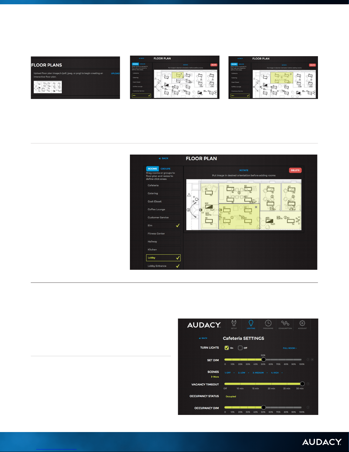
7.2 ADJUSTING ROOM SETTINGS
SCHEDULE – Sets the occupied
state of the room according to a
recurring weekly schedule.
TURN LIGHTS – ON, Lights turn on,
OFF, Lights turn off.
SET DIM - Set the dim level of
lights. 10% = minimum light, 100% =
maximum light.
DIM MAXIMUM – Sets the maximum
true dim level of the lights.
SCENES – Customizable settings to
enable one-touch lighting changes.
VACANCY TIMEOUT – Sets the
amount of time after which lights turn
off when room is vacant.
OCCUPANCY STATUS – Shows
when a room is occupied or not.
OCCUPANCY DIM – Set the default
occupied dim level of the lights. 10%
= minimum light, 100% = maximum
light. Lights will turn on with motion to
specied dim level.
VACANCY DIM – Set the default
vacancy dim level of the lights. 0%
= minimum light, 100% = maximum
light. Lights will turn on when room is
vacant to the specied dim level.
LIGHT SENSOR – Set desired
light level of room including all light
sources*.
*Note: while increments shown on Interface
are 10%, adjustments can be made in 1%
increments
7.3 CONFIGURING SCENES
The Scenes feature provides the ability to create and easily switch between 16 custom lighting congurations within a room.
A Scene conguration is easily created by setting the lights to the desired settings and then saving the scene.
1. From the Lighting menu, select the room to which a
scene will be saved.
2. Select the dropdown arrow next to the scene number
in order to:
• Save Current Scene – Saves scene to current light
level in the room.
• Rename Scene – Customize name of scene.
• Open Advanced Scene Editor – Enables
conguration of scenes at the light xture level for
additional customization of scene settings.
3. To rename the Scene, select the dropdown arrow
next to the scene number you want to rename and
click Rename Scene and type in desired name.
4. With the Advanced Scene Editor, you can adjust
settings at a Luminaire Controller level to set scenes.
Use the slider bar to set the desired light level of
a Luminaire Controller in the room. The “NOW”
indicator on each slider shows the current level for
each Luminaire Controller. Click TRIGGER SCENE
to preview the scene that is being congured in the
space. Then click SAVE.
5. To activate any scene, click on the name of the scene.
19
CONFIGURE 7.0 SYSTEM CONFIGURATION
Page 20

CONTROL
20
Page 21

8.0 SYSTEM CONTROL AND OPERATION
8.1 CREATING A ROOM GROUP
When two or more Rooms are tied together, a “Room
Group” is created. While it is not necessary to create
Room Groups in an Audacy® Wireless Controls system,
controlling a Room Group allows a user to turn on, off and
dim more than one Room simultaneously. Greater levels of
control can be found at the Room level only.
Some examples of typical Room Groups include:
• A particular oor on a multi-story building
• Several Rooms in a given portion of a building, e.g.,
“West side”
1. From the Setup menu click SETUP Room Group.
2. Enter a name for the Room Group.
3. Select Rooms to include in the Room Group and click
CREATE to save the Room Group.
4. Groups of Room Groups may also be setup. Click
Room GroupS and select from list of Room Groups
previously created.
8.2 ADDING AUTHORIZED USERS
An authorized user has access to the LIGHTING and
CONSUMPTION menus of AudacyControls.com but
access is limited to the assigned Rooms and Room Groups
only. ACCOUNT access is limited to CHANGE PASSWORD
but SETUP access is restricted.
1. Click ACCOUNT.
2. Click ADD AUTHORIZED USER.
3. Fill in the email address of the Authorized User.
4. Select the Room Group(s) and Room(s) to which you
want to assign control.
5. Click SUBMIT.
6. The User will receive an email with a temporary
password.
(Be sure to add “no-reply@audacycontrols.com”
to your email’s safe sender list)
21
CONTROL 8.0 SYSTEM CONTROL AND OPERATION
Page 22

8.3 BASIC SCHEDULING
Automatic schedules can be set up to turn off lights
according to a certain time of day, day of the week, or
particular date. The schedule for a given Room determines
the occupied state of the Room (e.g., Occupied or
Unoccupied).
1. Occupied
• Lights must be turned on manually; they do not
turn on automatically at the start of the Occupied
scheduled time.
• Vacancy timeouts are ignored and lights that are
manually turned on during the Occupied time will stay
on until they are manually turned off.
• If lights are on at the time the schedule reaches the
Unoccupied time, the Audacy® Wireless Controls
system will provide a 60-second ash as a warning
that the lights will be turning off in 60 seconds.
2. Unoccupied
8.3.1 CREATING A SCHEDULE FOR A GIVEN ROOM:
• Any lights that are turned on manually will stay on
for the duration set by the Vacancy Timeout before
automatically turning off once again.
• The Audacy Wireless Controls system will provide
a 60-second ash as a warning that the lights will
be turning off in 60 seconds.
Note: Most spaces typically use either motion sensors
or scheduling. If a space is using both motion sensors
and scheduling, then:
• During Occupied scheduled times, motion sensors
will automatically turn on lights upon motion detection
but will not turn them off if the space becomes vacant
until after the Unoccupied portion of the schedule has
been reached.
• During Unoccupied scheduled times, motion sensors
will automatically turn on lights upon motion detection
but will automatically turn off after reaching the Room
vacancy timeout period, regardless of whether the
space is occupied.
1. From the LIGHTING menu, select the Room to which
a schedule will be added.
2. Click SHOW next to SCHEDULE.
3. Select from Hour, 30 min or 15 min time blocks.
4. Click or click and drag to select the blocks of time for
which the space is to be designated as OCCUPIED.
5. Click again to deselect.
6. Click SAVE to save the schedule.
22
CONTROL 8.0 SYSTEM CONTROL AND OPERATION
Page 23
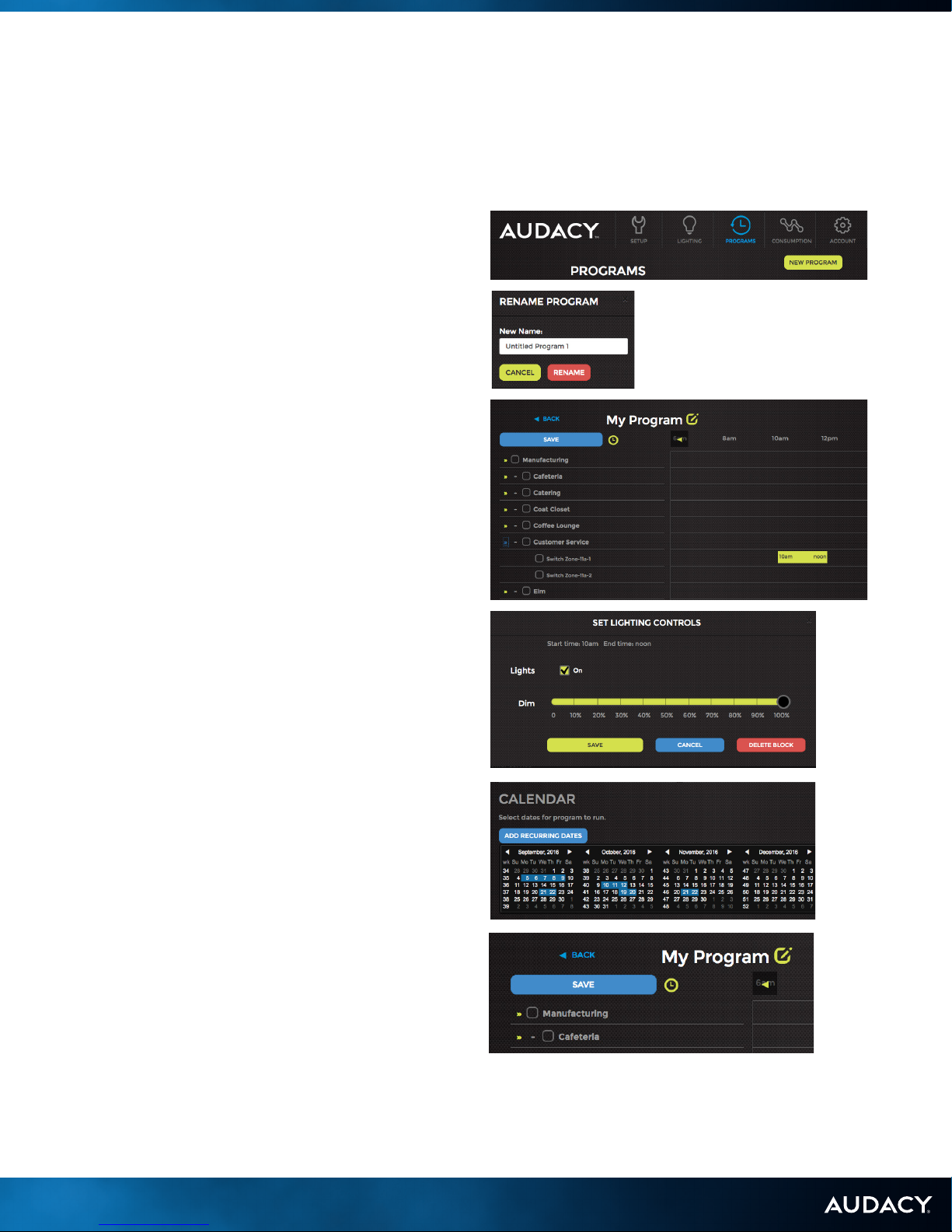
8.4 ADVANCED SCHEDULING (PROGRAMS)
The Advanced Scheduling feature provides more granular control over scheduling the lighting system. You can set
schedules across multiple Room Groups and/or Rooms, as well as schedule lighting parameters such as on/off, dim, and
scenes. You can also program multiple schedules, such as a day schedule and night schedule, that can be implemented on
specic dates or recurring days of the week.
There is a reference video that illustrates the entire setup
process on AudacyControls.com for visual reference.
1. Click PROGRAMS.
2. Click NEW PROGRAM in the upper right hand corner.
3. To rename a program, click on the EDIT icon next
to the program title (the default title is “Untitled
Program”). A RENAME PROGRAM dialog box will
appear. Enter your desired name and click RENAME.
4. In the left hand column you will see a list of all Room
Groups. Click the small yellow drop-down triangles
on the left to expand the group and see Rooms
contained within the group. Individual Rooms can
also be expanded to see switches within the Room.
Once you have located the Room Group, Room, or
switch for which you would like to schedule lighting,
click and drag in the timeline area on the right to
create a time block.
5. You can modify the time block by performing the
following actions:
a. Extend the beginning or ending time by clicking
and dragging on either end of the time block.
b. Move the time block by clicking and holding the
center of the block, and then drag to the desired
position.
c. Click once on the time block to open lighting
control options. If you are editing a Room, you will be
able to control the dim setting or set the lighting to a
scene. If you are editing a switch, you will be able to
control the dim settings. Click SAVE to conrm your
changes. You are also able to remove the time block
from this dialog box by clicking DELETE BLOCK.
6. Once all the desired lighting schedules are created,
scroll to the bottom of the page to access the
calendar. Select all the dates on which you would
like the program to run. You can also schedule the
program to run on recurring days of the week by
clicking ADD RECURRING DATES.
7. Click SAVE in the upper left hand corner to save the
program. You’ll be taken back to the program list
page.
NOTE: This schedule will be effective for 12 months
from the date you start.
23
CONTROL 8.0 SYSTEM CONTROL AND OPERATION
Page 24

8.4 ADVANCED SCHEDULING (CONT.)
8. The program settings can be changed at any time
by clicking on the program title. Additionally you can
extend or remove upcoming dates directly from the
program list view (NOTE: only the 3 upcoming dates
are displayed in the program list view.)
a. To remove a date, click REMOVE – located to the
right of the date.
b. To extend a date, click EXTEND. The EXTEND
PROGRAM dialog box will appear. Enter the amount
of time you would like to extend in format HH:MM
(1:30 is 1 hour and 30 minutes). By default, this time
will be applied to the end of the schedule. So, if the
schedule was originally going to end at 7:15pm, an
extension value of “1:30” will ensure the schedule
lasts until 8:45pm. If you would like to extend the
program start in order to start the program early,
click the checkbox EXTEND START. Click SAVE
EXTENSION.
9. To delete the program, click on the program title, then
scroll to the bottom of the page and click DELETE
PROGRAM. You must conrm the deletion before the
program is removed.
10. To duplicate a program, click on the program title, then
scroll to the bottom of the page and click DUPLICATE
PROGRAM. Once this button is clicked, you will
immediately be taken to the duplicated program
where you can make any desired modications. To
avoid confusion, make sure to rename the program by
scrolling to the top of the page and clicking the edit
icon next to the program title.
8.5 UPLOADING FLOOR PLANS
Uploading a oor plan image is the rst step to enable an
interactive oor plan. The oor plan can be in PDF, JPEG,
or PNG format.
1. Click SETUP.
2. Scroll down the page to FLOOR PLANS and click
UPLOAD.
3. Select the le of the image of your oor plan and
click OPEN.
24
CONTROL 8.0 SYSTEM CONTROL AND OPERATION
Page 25
8.6 ASSIGNING ROOMS TO FLOOR PLANS
1. Click on the newly uploaded
image within the FLOOR PLANS
box in the SETUP menu.
4. Repeat until all Rooms have
been added to the oor plan.
5. To edit a Room click on the
Room and move it or resize it.
6. To remove a Room from the oor
plan click on the Room and then
click the “X”.
7. To delete the entire oor plan
click DELETE in the upper right
hand corner.
2. All dened Rooms will be
listed on the left hand side of
the screen. Click on a Room
and drag it to the appropriate
location on the oor plan.
3. Once it is in the proper location
you can click on an edge or
corner of the Room to size it
appropriately.
8.7 CONTROLLING LIGHTS
8.7.1 WITHIN THE SPACE
Press the up or down arrow on any switch to adjust the
brightness or the ON or OFF button to control the light
xtures assigned to it. Pressing the up arrow while the lights
are off will turn the lights on at the lowest DIM setting.
8.7.2 FROM AUDACYCONTROLS.COM AND
APP
You can also control your light xtures from a computer,
tablet or smart phone using AudacyControls.com or the
Audacy® iOS® app. AudacyControls.com and the app
enable control of turning light xtures ON/OFF, setting the
DIM level or selecting a customizable SCENE.
25
CONTROL 8.0 SYSTEM CONTROL AND OPERATION
Page 26

9.0 CONSUMPTION REPORTS
Energy consumption is calculated using the data you
provided during Luminaire Controller conguration. Click
CONSUMPTION from the main AudacyControls.com
menu. There are multiple options available to utilize the
consumption data.
9.1 OVER TIME
This report allows you to view a historical record of
consumption that can be broken down to a specic date
range, room and time period.
Note: You must click UPDATE to refresh the graph after the
desired data is selected.
SOURCE – Choose to view the consumption of all rooms or select
a specic room to view.
DATE RANGE – Select a start and an end date to view the
consumption data between those dates.
BY – Select the time period each data point on the graph will
represent: Day, Week or Month.
Note: Power Consumption is a calculated value based on the duration that the light fixtures are on. Other factors like dim levels
set and the values input for voltage, power factor and Ampere draw will affect calculations (see section 6.2.6). Fluorescent lamp
power consumption data uses a modified 0-10V dimming curve that reflects a typical non-linear characteristic. For typical LED
fixtures, a linear 0-10V dimming curve is used.
9.2 BY AREA
This report allows you to view a historical record of
consumption that can be broken down by location over a
specic date range.
Note: You must click UPDATE to refresh the graph after the
desired date range is selected
9.3 EXPORTING CONSUMPTION DATA
Click EXPORT CSV on the left hand side of the screen to download a CSV le for the selected Date Range containing the
Date, Room Name, and associated Watt Hours.
9.4 BUILDING AUTOMATION INTEGRATION
The Audacy® Wireless Controls system can be tied into a Building
Automation System if desired. The Gateway can interface with a
wide range of BAS protocols including BACnet®/IP, BACnet®/MSTP,
Modbus TCP, Metasys® N2, Modbus RTU and LonWorks®. For
specic requirements please call Audacy Customer Service at
800-273-9989 for assistance with integrating Audacy with your BAS.
The BAS controls lights at the room level. The following elds are
available to the BAS:
Room:
• Occupancy Status (Read Only)
• Vacancy Timeout (Read Only)
• State (Read and Write)
• Value 0-100: 0 = relay off, 1-100 = DIM level
• Scene 1, 2, 3 or 4
• Switch: Battery Voltage (Read Only)
• State (Read and Write)
• Value 0-100: 0 = relay off, 1-100 = DIM level
• Occupancy Sensor: Battery Voltage (Read Only)
• Light Sensor: Light Level and Battery Voltage
(Read Only)
26
CONTROL 9.0 CONSUMPTION REPORTS
Page 27

APPENDIX
27
Page 28

A: SAFETY AND REGULATORY INFORMATION
1.1 UL INFORMATION
GW-1100 (Wireless Gateway) UL 2043 Plenum rated
SCL-1000 (Luminaire Controller, Internal-Mount) UL 916 (Energy Management Equipment), UL 2459 (Luminaire
Disconnect), UL 94 5VA (Enclosure)
SCD-1000 and ESCD-1000 (Luminaire Controller, External-Mount) UL 916 (Energy Management Equipment), UL 94
5VA rating (Enclosure)
1.2 FCC INFORMATION
GW-1100 (Wireless Gateway) FCC ID: SCL-1000 (Luminaire Controller) FCCID: 2AAMXSD1000
SCD-1000 and ESCD-1000 (Luminaire Controller, External-Mount) FCCID: 2AAMXSCD1000
SS-1200 (Remote Switch) FCC ID: WMS-1200 (Wall-Mount Switch) FCC ID: 2AAMXWMS1200
VSC-1300 (Ceiling-Mount Motion Sensor) FCC ID: 2AAMXVSC1300
VSW-1300 (Wall-Mount Motion Sensor) FCC ID: 2AAMXVSW1300
LS-1400 (Light Sensor) FCCID: 2AAMXLS1400
1.3 INDUSTRY CANADA INFORMATION
GW-1100 (Wireless Gateway) IC: 11250A-GW110B
SCL-1000 (Luminaire Controller) IC: 11250A-SCL1000
SCD-1000 and ESCD-1000 (Luminaire Controller, External-Mount) IC 11250A-SCD1000
SS-1200 (Remote Switch) IC: 11250A-SS1200
WMS-1200 (Wall-Mount Switch) IC: 11250A-WMS1200
VSC-1300 (Ceiling-Mount Motion Sensor) IC: 11250A-VSC1300
VSW-1300 (Wall-Mount Motion Sensor) IC: 11250A-VSW1300
LS-1400 (Light Sensor) IC: 11250A-LS1400
28
APPENDIX
Page 29

B: PRE-COMMISSIONING CHECKLIST
GATEWAY
¨ Gateway is installed, has power and is accessible
¨ Ethernet Drop for network connectivity is available for Gateway
¨ IP address has been assigned for Gateway
• If a static IP is being used, the appropriate Netmask, Gateway IP and DNS address for Gateway
are to be made available prior to commissioning
• If DHCP is to be used, a MAC reservation must be created prior to commissioning
¨ User name and password for Gateway have been created and made available
¨ Advanced scheduling has been set up (optional, requires valid NTP server address)
PROXY
¨ Server has been selected to host proxy software
• Windows 7 or better
- 2GHZ CPU minimum
- 2GB RAM minimum
- 10MBPS network interface
• Mac OS
• Linux
¨ Port 993 (outgoing) open to the Internet
¨ Proxy has network connectivity to all Gateways
PHYSICAL INSTALLATION
¨ All Luminaire Controllers installed per plan
¨ All sensors and switches powered on and installed per plan
DATA COLLECTION
¨ Detachable bar code label from each Luminaire Controller, sensor and switch have been removed and placed
on reflected ceiling plan or other document to record location of each device
¨ Fixture information recorded for accurate consumption reporting
• Voltage
• Amp draw
• Power factor
• Bulb type
CONFIGURATION
¨ Desired Room names and Room Groups have been provided
¨ Floor plan image (PDF, JPEG or PNG) provided for visual Room selection (optional)
¨ Scheduling, Occupancy or Vacancy defined for each Room
• Vacancy timeout
• Occupancy/Vacancy dim
• Schedule (if applicable)
¨ Up to four Scenes defined for each Room (optional)
• Scene name
• Desired light levels for each Luminaire Controller for each scene
¨ Upper and lower light levels for daylight harvesting areas defined
PERSONNEL AVAILABILITY
¨ Authorized person available to walk through space to answer questions on configuration and sign off on final
commissioning
¨ Person(s) are available for Audacy system operation training upon completion of commissioning
29
APPENDIX
Page 30

C: DEFAULT SETTINGS
High End Trim: 100%
Occupancy Dim: 50%
Vacancy Timeout: Off
Scene 1: Off, 0%; Scene 2: Low, 30%; Scene 3: Medium, 60%; Scene 4: High, 100%
Vacancy DIM: Off, 0%
DIM Maximum: 100%
Switches turn lights on at 100%
Light sensor: Low Threshold 0FC, High Threshold 230FC
Motion sensors: Vacancy
30
APPENDIX
Page 31

D: DEVICE INFORMATION
LUMINAIRE CONTROLLERS
External-Mount
Installs using a knockout on a junction box or xture
to provide control of individual or groups of xtures.
Available for LVDC, ELV Dimming, Metal, and Line Dimming
installations.
SCD-1000
SCDMET-1000
ESCD-1000
SCLINE-1000
SCELV-1000
Internal-Mount
Installs inside a light xture and provides control of
individual or groups of xtures. Available for 347V and
LVDC installations.
SCL-1000
SCC-1000
ESC-1000
SWITCHES
Remote
Device specially designed to allow building occupants to
turn on, turn off or dim light xtures assigned to it.
™
SS-1200 WS S -120 0
Wall-Mount
Wall-mount switch that replaces traditional wired
switches.
WM S -120 0 WM S -1201
Scene
Wall-mounted device that can be used to replace an
existing, wired switch. Four preset settings to control
scenes. or dim light xtures assigned to it.
31
APPENDIX
Page 32

D: DEVICE INFORMATION
GATEWAY
Centralized processing hub, wirelessly receives
and prioritizes inputs from sensors, switches and
AudacyControls.com to Luminaire Controllers to turn on,
off or dim light xtures, or control plug loads.
GW-110 0
SENSORS
Ceiling-Mount Motion
Infrared ceiling-mount device detects occupancy and/
or vacancy for control of light xtures. Can be mounted
anywhere a sensor is needed. Available for wide range and
high bay installations.
PLUG LOAD CONTROLLER
In-junction box device that can turn on or off AC line
voltage to a receptacle.
RS-1800
Dual-Technology Motion
Infrared and ultrasonic device that detects occupancy and
vacancy. Mounts in the ceiling on a junction box.
HBS -1302VS C -1300 VSC -1301
Light Sensor
Detects ambient light in a space, providing daylight
harvesting capabilities. Can be mounted anywhere a sensor
is needed.
LS-1400
Wall-Mount Motion
Infrared wall-mount device detects occupancy and/
or vacancy for control of light xtures. Can be mounted
anywhere a sensor is needed.
VDT-1300
Room Partition
Partition sensor that sends commands to the Gateway
and Luminaire Controllers. Can be mounted anywhere a
partition sensor is needed.
™
RPS-2000
32
APPENDIX
VS W-130 0
Page 33

E: LUMINAIRE CONTROLLER REQUIREMENTS
MAXIMUM FIXTURES PER LUMINAIRE CONTROLLER
The following table can be used to determine the maximum number of xtures that can be connected to each Luminaire
Controller.
Voltage Maximum Wattage per
Luminaire Controller
120VAC 600W 10 1
240VAC 1200W 10 1
277VAC 1385W 10 1
Refer to your ballast or LED driver specifications
Maximum Dimming
Circuits (Sinked*) per
Luminaire Controller
Maximum Dimming
Circuits (Sourced*) per
Luminaire Controller
33
APPENDIX
Page 34

F: LUMINAIRE CONTROLLER ONE LINE DRAWINGS
ESCGRID-1000 PWM LUMINAIRE CONTROLLER
34
APPENDIX
Page 35

E: LUMINAIRE CONTROLLER REQUIREMENTS
ESCD-1000 LVDC LUMINAIRE CONTROLLER, EXTERNAL-MOUNT
35
APPENDIX
Page 36

F: LUMINAIRE CONTROLLER WIRING DIAGRAMS
SCC-1000 347V LUMINAIRE CONTROLLER AT FIXTURE
36
APPENDIX
Page 37

F: LUMINAIRE CONTROLLER WIRING DIAGRAMS
SCL-1000 LUMINAIRE CONTROLLER, INTERNAL-MOUNT AT FIXTURE
37
APPENDIX
Page 38

F: LUMINAIRE CONTROLLER WIRING DIAGRAMS
SCD-1000 LUMINAIRE CONTROLLER, EXTERNAL-MOUNT ON
JUNCTION BOX
38
APPENDIX
Page 39

F: LUMINAIRE CONTROLLER WIRING DIAGRAMS
SCD-1000 LUMINAIRE CONTROLLER, EXTERNAL-MOUNT ON FIXTURE
39
APPENDIX
Page 40

F: LUMINAIRE CONTROLLER WIRING DIAGRAMS
SCD-1000 LUMINAIRE CONTROLLER, EXTERNAL-MOUNT MULTI
FIXTURE
40
APPENDIX
Page 41

F: LUMINAIRE CONTROLLER WIRING DIAGRAMS
SCD-1000 LUMINAIRE CONTROLLER, EXTERNAL-MOUNT ON
JUNCTION BOX MULTI FIXTURE
41
APPENDIX
Page 42

G: SENSOR COVERAGE PATTERNS
G: SENSOR COVERAGE PATTERNS
WALL-MOUNT (MODEL VSW-1300)
42
APPENDIX
Page 43

F: LUMINAIRE CONTROLLER ONE LINE DRAWINGS
CEILING-MOUNT (MODEL VSC-1300)
43
APPENDIX
Page 44

G: SENSOR COVERAGE PATTERNS
WIDE RANGE CEILING-MOUNT (MODEL VSC-1301)
30 ft
20 ft
10 ft
10 ft
20 ft
30 ft
0
0
9 ft
1722 13 9 5 5 9 13 17 220
44
APPENDIX
ft
Page 45

G: SENSOR COVERAGE PATTERNS
30 ft
20 ft
10 ft
0
10 ft
20 ft
DUAL TECHNOLOGY (MODEL VDT-1300)
20 ft 10 ft
0
10 ft 20 ft
30 ft
20 ft
10 ft
9 ft
0
10 ft
20 ft
PIR SENSOR RANGE
ULTRASONIC SENSOR
MINOR MOTION RANGE
30 ft
30 ft
0
45
APPENDIX
059131722 5 9 13 17 22
ft
Page 46

G: SENSOR COVERAGE PATTERNS
HIGH BAY (MODEL HBS-1302)
40ft
30ft
20ft
10ft
0
10ft
0 ft
10 ft
20 ft
30 ft
20ft
30ft
40ft
40 ft
46
APPENDIX
0
10ft 20ft 30ft 40ft10ft20ft30ft40ft
Page 47

Duplicate as needed
ROOM
LOCATION
DEVICE TYPE
SERIAL #
47
APPENDIX
Page 48

P-5302 Rev. 11/16
48
IDEAL INDUSTRIES, INC.
1375 Park Ave. | Sycamore, IL 60178 | U.S.A.
www.audacywireless.com • 800-273-9989
contactus@audacywireless.com
 Loading...