

Page 1

IDEAL® Test and Measurement
61-827
Single Laser Targeting
Infrared Thermometer
5 Commonwealth Ave
Woburn, MA 01801
TestEquipmentDepot.com
Page 2

Table of Contents
Introduction ................................................................. 3
Contacting IDEAL INDUSTRIES, INC .................................... 3
Safety Information ......................................................... 4
Warnings .............................................................................................. 4
Cautions ............................................................................................... 4
Symbols ............................................................................................... 5
Operation................................................................6-10
Identification and description of operating controls and
functions ..........................................................................................6-7
Operating Features ............................................................................... 9
Meter Operation ..............................................................................9-10
Power On ............................................................................................. 9
Temperature Unit Setting ...................................................................... 9
Backlight/Laser Pointer On/Off ........................................................... 10
Emissivity Description ........................................................................ 11
Accuracy Diagram .............................................................................. 12
Spot Size to Distance ......................................................................... 13
Field of View ...................................................................................... 14
Functions Operation Table .................................................................. 15
Functions Indication Table ................................................................. 15
Measurement Specifications ........................................... 16
Environmental Specifications .......................................... 16
Mechanical Specifications ............................................. 17
EMC / EMI ................................................................. 17
FCC ...................................................................... 17
Safety ...................................................................... 17
Maintenance and Service .............................................. 18
Disposal and Warranty .................................................. 19
Introduction
2
Page 3

Introduction
The IDEAL 61-827 Single Laser Targeting Infrared Thermometer (IRT) is a
non contact temperature sensing meter. Its single laser defines the center of
the area whos temperature will be measured.
LASER
2
Eye damage or personal injury hazard. Follow all safety procedures. Read and
fully understand the instruction manuals prior to using this product. Failure to
comply can result in serious injury.
WARNING
2 3
Page 4

Safety Information
Laser
2
could result in serious injury if the hazard is realized.
Caution - Identifies conditions and actions that could result in meter
damage or an incorrect reading if the hazard is realized.
Eye damage or personal injury hazard. Follow all safety procedures. Read and fully
understand the instruction manuals prior to using this product. Failure to comply
can result in serious injury.
Warning - Identifies conditions and actions that
Laser
2
WARNING
• Choking Hazard, Small Parts. Keep Away from Children. This is not a
toy. It is not for use or play by children. Keep Away from Children. Failure
to do so can result in serious injury.
• Do not point the laser directly at people or animals.
• Do not look at the laser directly or through other optical tools
(telescope, microscope, binoculars) or reflected laser light.
• Do not come in contact with high temperature surfaces when making
measurements.
• Use of controls or adjustments or performance of procedures other
than those specified herein may result in hazardous radiation exposure.
• Do not use the thermometer in an environment close to flammable or
explosive materials.
• Cancer and Reproductive Harm
Laser
LASER RADIATION DO NOT STARE INTO BEAM
2
OUTPUT <1mW COMPLIES WITH EN60825-1:2014
CAUTION
Identifies conditions and actions that could result in meter damage or an incorrect
reading if the hazard is realized.
• Do not disassemble or modify the thermometer or laser.
• This unit has no serviceable parts.
• To avoid false readings, replace the batteries as soon as the low battery
indicator ( ) appears.
• Do not use without the batteries correctly in place and the battery door
closed and secured.
• Inspect the case before using the thermometer. Do not use the thermometer
if it appears damaged. Look for cracks or missing plastic.
• Using the thermometer around steam, dust, or environments with large
temperature fluctuations may lead to inaccurate temperature measurement.
• To ensure measurement accuracy, please place the thermometer in the
measurement environment for 30 minutes before using.
• Avoid keeping the thermometer near high temperature environment for
long periods.
• Clean the case and accessories with a damp cloth and mild detergents only.
Do not use abrasives or solvents. Make sure the meter is completely dry
before use.
Symbols & Descriptions
4
Page 5

Symbols & Descriptions
SYMBOL DESCRIPTION
Warning or Caution
Laser Radiation Warning
Laser Eye Hazard
LASER
Laser Class 2 Warning- Class 2 lasers are considered
safe for normal operation. Class 2 lasers’ output power is
2
below 1 milliwatt. All Class 2 lasers emit Visible light only.
Choking Hazard
Low Battery Indicator
LCD Liquid Crystal Display
Do not dispose of this product as unsorted municipal
waste. It must be properly disposed of in accordance
with local regulations.
Conforms to applicable North American Safety Standards
Conforms to applicable Australian Safety Standards
Conforms to European Directives
4 5
Page 6

Operation
Identification and Description of Operating
Controls and Functions for the Single Laser
Laser
6
:
2
Laser
2
Targeting Infra Red Thermometer
1. LCD Screen
2. Function Button (Under Battery Cover)
3. Battery Cover
4. Lanyard Attach Point
5. Trigger (Turns IRT On)
6. Laser Aiming Emitters
7. IR Lens
6
Page 7

6
7
5
1
2
3
4
6 7
Page 8

Display and Functions Indication Diagram
2 3
HOLD
1
1. Main Display
2. HOLD the last reading in the display
3. Laser Radiation Warning
4. Low Battery Indicator
5. Degrees Displayed in F or C
Function Description
1 Main 4 digit display
Measured Value is NOT being updated; last
2
value only is shown
3 Laser Radiation Warning (Laser is emitting)
4 Low Battery Indicator
5 Degrees F OR C have been selected
Operating Features
4
F
C
5
8
Page 9

Operating Features
Measured Surface Outline
A single press of the trigger results in a single area temperature of the surface
whose center is defined by the laser dot.
Scanning
Pressing the trigger quickly places the unit in scan mode which constantly
updates the temperature reading in the display as you aim at different targets.
To remain in scan mode, keep the trigger pressed.
Meter Operation
Power On
A Single Trigger pull turns the unit on and temperatures are immediately
calculated and the IRT displays the temperature of the surface it is pointed at.
Centered around the laser dot.
Taking a Reading
1. Pull and hold the trigger after aiming at the target. The measurement result
will be displayed in the LCD.
2. Release the trigger, and the HOLD icon appears, indicating that the
measurement has been stopped and the last measured value is held.
Viewing the Last Measured Value
When the unit is off, a short press (less than 0.5s) of the trigger turns the
thermometer on and the last measured temperature before the last shutdown
will be displayed.
Temperature Unit Setting
Located underneath the battery door cover is the Fahrenheit and Celsius and
button. With the 61-827 on, select the C or F scale by simply pushing the
button until F or C appears in the screen.
8 9
Page 10

Backlight/Laser Pointer
Pulling the trigger automatically turns the backlight on for 8 seconds and also
illuminates the laser pointer.
NOTE: During measurement, it is best to ensure that the measured target
diameter is twice the spot size (S) of the thermometer, and then determine the
test distance (D) according to the D:S diagram (refer to D:S part).
For example, if you use the 61-827 to measure the temperature of an object
with a diameter of about 4” (10cm), then according to the above, the spot
size (S) of the thermometer should be about 2” (5cm) for highest accuracy,
and according to the D:S diagram, the measured distance (D) is about 20”
(50 cm).
Auto Power Off
If there is no operation for 8 seconds, the thermometer will automatically
power off and save the currently held measurement.
10
Page 11

Emissivity
Emissivity is the term used to describe the efficiency with which a particular
surface emits Infra-Red Radiation IN THE WAVELENGTHS that are detectable
by the sensor in the IR Thermometer. Its sensitivity is in the 8 to 14-micron
wavelength range. To be sure, a hot mass will radiate IR in many different
wavelengths, but the sensing technology employed in this type of instrument
has a narrow bandwidth. Some materials, such as electrical tape, human
skin, certain types of paints are efficient emitters in these Wavelengths.
Others such as aluminum, brass, and gold are inefficient emitters, again, IN
THESE WAVELENGTHS. Heat a bar of gold to 200 degrees and try to read
its temperature and it will appear cold. Cover it in electrical tape, and scan
the tape, and the temperature will be much higher and much more accurate.
Please remember this when making measurements of certain objects. This can
and does greatly affect the accuracy of the readings.
Human Skin 0.98
Smooth Ice 0.96
Carbon Candle Soot 0.95
Oil Based Paint 0.94
White Bond Paper 0.93
Snow 0.85
Stainless Steel 0.85
Oxidized Copper 0.78
Rust 0.71
Cast Iron 0.64
Buffed Stainless Steel 0.16
Polished Brass 0.03
10 11
Page 12

Best Accuracy Coverage
Average Accuracy Coverage
Poor Accuracy Coverage
12
Page 13

Spot Size to Distance
The measured surface area can represent a cone emanating out from the
sensor. The further the distance to the surface, the larger the area that will
influence temperature measurements. It is important that when it safe to do
so, get as close as possible to the target, using the single laser to define the
center of an imaginary circle. This will increase the accuracy of the displayed
temperature. Also, make measurements at 90 degrees to the surface as
angular measurements are less accurate. (Reference diagram below)
12 13
Page 14
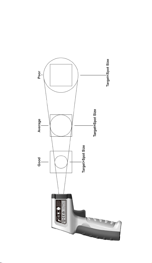
Field of View
HOLD SCAN
OK
LOHI
Make sure that the measured target is larger than the spot size. The smaller
the target, the closer the test distance should be (please refer to D:S for the
spot size at different distances). To obtain the optimum measurement result,
it is recommended that the target being measured is 2 times larger than the
spot size.
Functions Operations Table
14
Page 15

Functions Operations Table
HOLD SCAN
OK
LOHI
C F
C F
LOHI
HOLD
Button
Response
Backlight
or Laser On
or Off
Default
Function
Last Selection
Functions Indications Table
Low Battery Indicator
Temperature Hold
Indicator
Temperature Unit Indicator
Operation
Short press to toggle the
Backlight On and measure
the object one time. Long
press to toggle the laser On
and continuously measuring.
Release the trigger to hold
the measured value and
laser is off.
Main Display of the
Measured Temperature
Laser Indicator
F
C
14 15
Page 16

Measurement Specifications
Function Range Resolution Accuracy
61-827 ±(a%+b)
±3.6ºF or ±1.8% of reading,
whichever is greater
º
±1.8ºC or ±1.8% of reading,
whichever is greater
Time
-4ºF to 752ºF
(-20ºC to 400ºC)
10:1 NA
≤500ms (95% of
reading)
2°F or 1.0%,
whichever is
greater
Temperature
Emissivity 0.95 0.1
Distance to
Spot Ratio
Response
Repeatability
0.1
Environmental Specifications
Operating Temperature: 32ºF to 122ºF (0ºC to 50ºC) (<80%RH)
Operating Altitude:
Storage Temperature:
Intended for indoor use.
6500 ft (2000 m)
-4ºF to 140ºF (-20ºC to 60ºC) (<80%RH)
47 CFR 15 subpart B. This product is considered an exempt device per clause
15.103.
16
Page 17

Mechanical Specifications
Dimensions: (L x W x H) 5.75 in. x 1.5 in. x 3 in.
Weight:
Display:
Display Count:
Power Source:
Battery Life: Continuous temperature measurement
Wavelength:
Beam Divergence:
Parallel:
Perpendicular:
Maximum Power Output:
(146 mm. x 38 mm. x 70 mm.)
0.3 LBS (0.15 KG)
LCD
9999
2 x 1.5V AAA
greater than 12 hours typical
655nm
7 Degrees
38 Degrees
<1mW
EMC/EMI
CISPR 22 3rd Edition. Class B Limits.
EN 55032
CISPR 32
CISPR 11
FCC 15. 107 with reference to Section 15.109 (g).
ICES-003
EN 61326-2-2 Sec 6.4.2.101
USA (FCC)
47 CFR 15 subpart B. This product is considered an exempt device per clause
15.103.
Safety
Complies with the following:
UL 61010-1, 3rd Edition, May 11, 2012, Revised November 21, 2018, CAN /
CSA-C22.2 No. 61010-1-12, 3rd Edition, Amendment 1: 2018, Revision dated
November 21 November 2018
IEC 60825-1
21CFR 1002.13
Complies with 21 CFR 1040.10 and 1040.11 except for conformance with IEC
16 17
60825-1 Ed.3 as described in Laser Notice No. 56 dated May 8, 2019.
Page 18

Maintenance and Service
Equipment Maintenance and Service
Meter Inspection
Do not use if meter appears damaged. Visually inspect the meter to ensure
case is not cracked.
Battery Inspection/Replacement
Inspect the battery compartment monthly for any signs of degradation. Low
battery voltages will cause inaccuracies in readings. Remove the batteries
for storage or if the meter will not be used for longer than one month. Battery
leakage will compromise the safety of the meter and cause irreparable damage
to internal components.
Maintenance and Storage
Switch off and disconnect the meter completely before carrying out any
maintenance. Clean the case with a damp cloth and mild detergent. Do not
use abrasives or solvents. Keep away from liquids and ensure the meter is
completely dry before use.
Service and Replacement Parts
This unit has no serviceable parts.
18
Page 19

Disposal of Waste, Electrical & Electronic Equipment
In order to preserve, protect and improve the quality of the environment, protect
human health and utilize natural resources prudently and rationally, the user
should return unserviceable product to relevant facilities in accordance with
statutory regulations. The crossed-out wheeled bin indicates the product needs to
be disposed separately and not as municipal waste.
Do not dispose of this product as unsorted municipal waste. It must be properly
disposed of in accordance with local regulations.
Disposal of Used Batteries/Accumulators
The user is legally obliged to return used batteries and accumulators. Disposing
used batteries in household waste is prohibited! Batteries/accumulators containing
hazardous substances are marked with the crossed-out wheeled bin. The symbol
indicates that the product is forbidden to be disposed via domestic refuse. The
chemical symbols for the respective hazardous substances are Cd = Cadmium, Hg
= Mercury, Pb = Lead.
You can return used batteries/accumulators free of charge to any collecting point of
your local authority, our stores, or where batteries/accumulators are sold.
Consequently, you must comply with your legal obligations and contribute to
environmental protection.
TWO YEAR LIMITED WARRANTY
This tester is warranted to the original purchaser against defects in material and
workmanship for a period of two (2) years from date of purchase. With proof of
purchase from an authorized IDEAL distributor, a defective tester will be repaired or
replaced with the same product or a functionally equivalent product, at the option of
IDEAL INDUSTRIES, INC. during the warranty period, subject to verification
of the defect or malfunction. Warranty does not cover consumables such as fuses,
batteries, and excludes defects caused by leakage from batteries, abuse,
mishandling, dropping, ordinary wear and tear, misuse, neglect, unauthorized
repair, improper use, alterations, accidents or any causes beyond IDEAL’s
reasonable control. Consequential or incidental damages are not recoverable under
this warranty. Some states do not allow the exclusion or limitation of incidental or
consequential damages, so the above limitation or exclusion may not apply to you.
This LIMITED WARRANTY gives you specific legal rights, which vary from state to
state. This warranty constitutes the sole and exclusive remedy of the purchaser and
the exclusive liability of IDEAL, and is in lieu of any and all other warranties, and
expressly disclaims all other warranties, implied, or statutory as to merchantability,
fitness for purpose sold, description, quality productiveness, or any other matter.
No agent, distributor or other supplier has the authority to modify or amend this
warranty or make other representations or warranties other than those contained in
this warranty without express written authorization from IDEAL. For warranty
service, call IDEAL customer service at 1-800-635-0705.
Made in China.
18 19
Page 20

Scan the barcode on the right to see the new IDEAL T&M Product Line
Page 21

IDEAL® Prueba y Medición
61-827
Termómetro Infrarrojo de
Focalización de Láser Singular
Instrucciones en español adentro / Instructions en français à l’intérieur
21
Page 22

Índice
Introducción .............................................................. 23
Cómo contactar a IDEAL INDUSTRIES, INC. ......................... 23
Información de Seguridad .............................................. 24
Advertencias ....................................................................................... 24
Precauciones ...................................................................................... 24
Símbolos ............................................................................................ 25
Operación 6-10
Identificación y descripción de controles de operación y
funciones ......................................................................................26-27
Funciones de Operación ................................................................28-29
Operación del Medidor ..................................................................29-30
Encendido............................................................................... 29
Configuración de la Unidad de Temperatura ........................... 29
Encendido/Apagado de Luz de Fondo/Puntero Láser.............. 30
Descripción de Emisividad ..................................................... 31
Diagrama de Precisión............................................................ 32
Tamaño del Punto a Distancia .................................................33
Campo de Visión .................................................................... 34
Tabla de Operaciones de Funciones ................................................... 35
Tabla de Indicación de Funciones ...................................................... 35
Especificaciones de Medición ......................................... 36
Especificaciones Ambientales ......................................... 36
Especificaciones Mecánicas ........................................... 37
EMC/EMI................................................................... 37
FCC ...................................................................... 37
Seguridad ................................................................. 37
Mantenimiento y Servicio .............................................. 38
Eliminación y Garantía .................................................. 39
Introduction
22
Page 23

Introduction
El Termómetro Infrarrojo de Focalización de Láser Singular (TIR) IDEAL
61-827 es un medidor de detección de temperatura sin contacto. Su láser
singular define el centro de la zona cuya temperatura se medirá.
LASER
2
Peligro de daños a los ojos o lesiones personales. Siga todos los
procedimientos de seguridad. Lea y comprenda completamente los manuales
de instrucciones antes de usar este producto. El incumplimiento puede
resultar en lesiones graves.
ADVERTENCIA
22 23
Page 24

Información de Seguridad
Laser
2
que podrían provocar la muerte o lesiones graves si se toma el riesgo.
Precaución - Identifica condiciones y acciones que podrían resultar
en daños al medidor o en una lectura incorrecta si se toma el riesgo.
Peligro de daños a los ojos o lesiones personales. Siga todos los procedimientos
de seguridad. Lea y comprenda completamente los manuales de instrucciones
antes de usar este producto. El incumplimiento puede resultar en lesiones graves.
Advertencia - Identifica condiciones y acciones
Laser
2
ADVERTENCIA
Peligro de Asfixia, Partes Pequeñas. Mantener Fuera del Alcance de los
Niños. Esto no es un juguete. No es para uso o juego de niños. Mantener
Fuera del Alcance de los Niños. No hacerlo puede resultar en lesiones graves.
No apunte el láser directamente a personas o animales.
No mire al láser directamente o a través de otras herramientas ópticas
(telescopio, microscopio, binoculares) o luz láser reflejada.
No entre en contacto con superficies de alta temperatura al realizar
mediciones.
El uso de controles o ajustes o la realización de procedimientos distintos a
los especificados en este documento pueden provocar una exposición
peligrosa a la radiación.
No utilice el termómetro en un entorno cercano a materiales inflamables o
explosivos.
Laser
RADIACIÓN LÁSER NO MIRAR HACIA EL RAYO, SALIDA
2
<1 mW CUMPLE CON EN60825-1:2014
PRECAUCIÓN
Identifica condiciones y acciones que podrían resultar en daños al medidor o en una
lectura incorrecta si se toma el riesgo.
• No desarme ni modifique el termómetro ni el láser.
• Esta unidad no tiene partes reparables.
• Para evitar lecturas falsas, reemplace las baterías tan pronto como aparezca el
indicador de batería baja ( ).
• No lo use sin las baterías correctamente colocadas y la puerta de la batería cerrada
y asegurada.
• Inspeccione la carcasa antes de usar el termómetro. No use el termómetro si
parece dañado. Busque grietas o plástico faltante.
• El uso del termómetro cerca de vapor, polvo o entornos con grandes fluctuaciones
de temperatura puede dar lugar a mediciones de temperatura inexactas.
• Para garantizar la precisión de la medición, coloque el termómetro en el
entorno de medición durante 30 minutos antes de usarlo.
• Evite mantener el termómetro cerca de un ambiente de alta temperatura durante
períodos prolongados.
• Únicamente limpie la carcasa y los accesorios con un paño húmedo y deter
gentes suaves. No utilice abrasivos o solventes. Asegúrese de que el medidor
esté totalmente seco antes de usar.
Símbolos y Descripciones
24
Page 25

Símbolos y Descripciones
SÍMBOLO DESCRIPCIÓN
Advertencia o Precaución
Advertencia de Radiación Láser
Peligro Ocular con Láser
LASER
Advertencia de Láser de Clase 2: Los láseres de Clase 2
se consideran seguros para el funcionamiento normal. La
2
potencia de salida de los láseres de Clase 2 es inferior
a 1 milivatio. Todos los láseres de Clase 2 sólo emiten
luz visible.
Peligro de Asfixia
Indicador de Baterías Bajas
LCD Pantalla de Cristal Líquido
No elimine este producto como residuo municipal sin
clasificar. Debe desecharse adecuadamente de
acuerdo con las regulaciones locales.
Cumple con los Estándares de Seguridad Norteamericanos
aplicables
Cumple con los Estándares de Seguridad Australianos
aplicables
Cumple con las Directivas Europeas
24 25
Page 26

Operación
Identificación y Descripción de Controles
de Operación y Funciones del Termómetro
Infrarrojo de Focalización de Láser único :
1. Pantalla LCD
2. Botón de Función (Bajo la Tapa de la Batería)
3. Tapa de Batería
4. Punto de Sujeción de Cordón
5. Gatillo (Enciende el TIR)
6. Emisor de Puntería Láser
7. Lente IR
Laser
2
Laser
6
2
26
Page 27

6
7
5
1
2
3
4
26 27
Page 28

Diagrama de indicación de funciones y visualización
Funciones de Operación
2 3
HOLD
1
1. Pantalla Principal
2. RETENER la última lectura en la pantalla
3. Advertencia de Radiación Láser
4. Indicador de Baterías Bajas
5. Grados Mostrados en F o C
Función Descripción
1 Pantalla principal de 4 dígitos
El Valor Medido NO se está actualizando; sólo
2
se muestra el último valor
Advertencia de Radiación Láser (El láser está
3
emitiendo)
4 Indicador de Baterías Bajas
5 Se han seleccionado los grados F o C
4
F
C
5
28
Page 29

Funciones de Operación
Contorno de la Superficie Medida
Una pulsación singular del gatillo resulta en una temperatura de área singular
de la superficie cuyo centro es definido por el punto láser.
Escaneo
Al presionar el gatillo rápidamente coloca la unidad en modo de escaneo, que
actualiza constantemente la lectura de temperatura en la pantalla mientras
apunta a diferentes objetivos. Para permanecer en modo de escaneo,
mantenga pulsado el gatillo.
Operación del Medidor
Encendido
Un Tirón Singular del Gatillo enciende la unidad y las temperaturas se
calculan inmediatamente y el TIR muestra la temperatura de la superficie a la
que apunta. Centrado alrededor del punto laser.
Tomar una Lectura
1. Apriete y mantenga presionado el gatillo después de apuntar al objetivo. El
resultado de la medición se mostrará en la pantalla LCD.
2. Suelte el gatillo, y aparece el ícono HOLD, indicando que la medición se
ha detenido y el último valor medido se retiene.
Visualización del Último Valor Medido
Cuando la unidad está apagada, una presión corta (menos de 0.5 s) del gatillo
enciende el termómetro y se mostrará la última temperatura medida antes del
último apagado.
Configuración de la Unidad de Temperatura
El botón de Fahrenheit y los Celsius está situado debajo de la tapa de la
batería. Con el 61-827 encendido, seleccione la escala C o F simplemente
empujando el botón hasta que F o C aparezca en la pantalla.
28 29
Page 30

Luz de Fondo/Puntero Láser
Apretar el gatillo enciende automáticamente la luz de fondo durante 8 segundos y también se ilumina el puntero láser.
NOTA: Durante la medición, es mejor asegurarse de que el diámetro objetivo
medido sea el doble del tamaño del punto (S) del termómetro y luego determinar la distancia de prueba (D) de acuerdo con el diagrama D:S (consulte la
parte D:S).
Por ejemplo, si utiliza el 61-827 para medir la temperatura de un objeto con
un diámetro de aproximadamente 4” (10 cm), entonces de acuerdo con lo
anterior, el tamaño del punto (S) del termómetro debe ser de aproximadamente 2” (5 cm) para una mayor precisión, y de acuerdo con el diagrama D:S,
la distancia medida (D) es de aproximadamente 20” (50 cm).
Apagado Automático
Si no hay operación durante 8 segundos, el termómetro se apagará automáticamente y guardará la medición que se retiene actualmente.
30
Page 31

Emisividad
Emisividad es el término utilizado para describir la eficiencia con la que una
superficie en particular emite radiación infrarroja en las LONGITUDES DE
ONDA que son detectables por el sensor en el termómetro IR. Su sensibilidad
está en el rango de longitud de onda de 8 a 14 micras. Sin duda, una
masa caliente irradiará IR en muchas longitudes de onda diferentes, pero
la tecnología de detección empleada en este tipo de instrumento tiene un
ancho de banda estrecho. Algunos materiales, como la cinta eléctrica, la piel
humana, ciertos tipos de pinturas son emisores eficientes en estas longitudes
de onda. Otros como el aluminio, latón y oro son emisores ineficientes,
de nuevo, EN ESTAS LONGITUDES DE ONDA. Calienta una barra de oro a
200 grados y trate de leer su temperatura y aparecerá fría. Cúbrala en cinta
eléctrica y escanee la cinta, y la temperatura será mucho más alta y mucho
más precisa. Por favor, recuerde esto al hacer mediciones de ciertos objetos.
Esto puede y de hecho afecta en gran medida la precisión de las lecturas.
Piel Humana 0.98
Hielo Liso 0.96
Hollín de Carbono de Vela 0.95
Pintura a Base de Aceite 0.94
Papel Bond Blanco 0.93
Nieve 0.85
Acero Inoxidable 0.85
Cobre Oxidado 0.78
Óxido 0.71
Hierro Fundido 0.64
Acero Inoxidable Pulido 0.16
Latón Pulido 0.03
30 31
Page 32

Mejor Cobertura de Precisión
Cobertura de Precisión Media
Cobertura de Precisión Deficiente
32
Page 33

Tamaño del Punto a Distancia
El área de superficie medida puede representar un cono que emana del
sensor. Cuanto más lejos sea la distancia a la superficie, mayor será el área
que influirá en las mediciones de temperatura. Es importante que cuando sea
Seguro hágalo, acérquese lo más posible al objetivo, utilizando el láser único
para definirel centro de un círculo imaginario. Esto aumentará la precisión
de la temperatura mostrada. Además, realice mediciones a 90 grados de la
superficie, ya que las mediciones angulares son menos precisas. (Diagrama
de referencia a continuación)
Tamaño del spot Tamaño del spot Tamaño del spot
32 33
Page 34

Campo de Visión
HOLD SCAN
OK
LOHI
Asegúrese de que el objetivo medido es mayor que el tamaño del punto.
Cuanto menor sea el objetivo, más cerca debe estar la distancia de prueba
(consulte D:S para conocer el tamaño del punto a diferentes distancias). Para
obtener el resultado óptimo de la medición, se recomienda que el objetivo que
se está midiendo sea 2 veces mayor que el tamaño del punto. (Diagrama de
referencia a continuación)
Pobre
Objetivo<Tamaño del spot
Promedio
Objetivo=Tamaño del spot
Bueno
Objetivo>Tamaño del spot
Tabla de Operaciones de Funciones
34
Page 35

Tabla de Operaciones de Funciones
HOLD SCAN
OK
LOHI
C F
C F
LOHI
HOLD
Botón Respuesta
Backlight
or Laser On
or Off
Función
Predeterminada
Last Selection
Tabla de Indicación de Funciones
Indicador de Baterías
Bajas
Indicador de Retención de
Temperatura
Indicador de Unidad de
Temperatura
Pantalla Principal de la
Temperatura Medida
Indicador de Láser
Operación
Short press to toggle
the Backlight On and
measure the object one
time. Long press to
toggle the laser On and
continuously measuring.
Release the trigger to hold
the measured value and
laser is off.
F
C
34 35
Page 36

Especificaciones de Medición
Función Rango Resolución Precisión
61-827 ±(a%+b)
±3.6°F o ±1.8% de la
º
lectura, el que sea mayor
±1.8°F o ±1.8% de la
lectura, el que sea mayor
Punto
-4ºF a 752ºF
(-20ºC a 400ºC)
10:1 NA
≤500ms (95% de
lectura)
2°F o 1.0%, el que
sea mayor
Temperatura
Emissivity 0.95 0.1
Relación
Distancia a
Tiempo de
Respuesta
Repetibilidad
0.1
Especificaciones Ambientales
Temperatura Operativa: 32ºF a 122ºF (0ºC to 50ºC) (<80%RH)
Altitud Operativa:
Temperatura de
Almacenamiento:
Destinado para uso en interiores.
6500 pies (2000 m)
-4ºF a 140ºF (-20ºC a 60ºC) (<80%RH)
36
Page 37

Especificaciones Mecánicas
Dimensiones: (L x An x Al) 5.75 pulg. x 1.5 pulg. x 3 pulg.
(146 mm. x 38 mm. x 70 mm.)
Peso: 0.3 LBS (0.15 KG)
Pantalla:
Conteo de Pantalla:
Fuente de Alimentación:
Vida Útil de las Baterías: Medición continua de la temperatura
Longitud de onda:
Divergencia del haz:
Paralelo:
Perpendicular:
Salida de potencia máxima:
0.3 LBS (0.15 KG)
LCD
9999
2 x 1.5V AAA
superior a 12 horas típico
655nm
7 Grados
38 Grados
<1mW
EMC/EMI
CISPR 22 3a Edición. Límites de Clase B.
EN 55032
CISPR 32
CISPR 11
FCC 15. 107 con referencia al artículo 15.109 (g).
ICES-003
EN 61326-2-2 Sec 6.4.2.101
EE. UU. (FCC)
47 CFR 15 subparte B. Este producto se considera un dispositivo exento
según la cláusula 15.103.
Seguridad
Cumple con lo siguiente:
UL 61010-1, 3.a edición, 11 de mayo de 2012, revisada el 21 de noviembre
de 2018, CAN / CSA-C22.2 No. 61010-1-12, 3ra Edición, Enmienda 1: 2018,
Revisión con fecha 21 de noviembre de 2018
IEC 60825-1
21CFR 1002.13
21 CFR 1040.10 y 1040.11 excepto por la conformidad con IEC 60825-1 Ed.3
36 37
como se describe en el Aviso de láser No. 56 del 8 de mayo de 2019.
Page 38

Mantenimiento y Servicio
Mantenimiento y Servicio de Equipos
Inspección del Medidor
No use el Medidor sí parece dañado. Inspeccione visualmente el medidor para
asegurarse de que la carcasa no esté agrietada.
Inspección/Reemplazo de las Baterías
Inspeccione el compartimiento de las baterías mensualmente por
cualquier seña de degradación. Los voltajes bajos de las baterías causarán
imprecisiones en las lecturas. Retire las baterías para su almacenamiento o
si el medidor no se utilizará durante más de un mes. Fugas de las baterías
comprometerán la seguridad del medidor y causarán daños irreparables a los
componentes internos.
Mantenimiento y Almacenamiento
Apague y desconecte el medidor por completo antes de realizar cualquier
mantenimiento. Limpie la carcasa con un paño húmedo y detergentes suaves.
No utilice abrasivos o solventes. Mantener alejado de líquidos y asegurarse de
que el medidor esté completamente seco antes de su uso.
Servicio y Repuestos
Esta unidad no tiene partes reparables.
38
Page 39

Eliminación de Residuos, Equipos Eléctricos y Electrónicos
Para preservar, proteger y mejorar la calidad del medio ambiente, proteger la salud
humana y utilizar los recursos naturales de manera prudente y racional, el usuario
debe devolver el producto inservible a las instalaciones pertinentes de acuerdo con
las regulaciones legales. El contenedor de basura tachado indica que el producto
debe desecharse por separado y no como basura municipal.
No elimine este producto como residuo municipal sin clasificar. Debe desecharse
adecuadamente de acuerdo con las regulaciones locales.
Eliminación de Baterías/Acumuladores Usados
legalmente obligado a devolver las baterías y acumuladores usados. ¡Está
prohibido eliminar las baterías usadas en los residuos domésticos! Las baterías/
acumuladores que contienen sustancias peligrosas están marcados con el
contenedor con ruedas tachado. El símbolo indica que está prohibido eliminar el
producto a través de la basura doméstica. Los símbolos químicos de las
sustancias peligrosas respectivas son Cd = Cadmio, Hg = Mercurio, Pb = Plomo.
Puede devolver las baterías/acumuladores usados de forma gratuita a cualquier
punto de colección de su autoridad local, nuestras tiendas o donde se vendan
baterías/acumuladores. En consecuencia, debe cumplir con sus obligaciones
legales y contribuir a la protección del medio ambiente.
GARANTÍA LIMITADA DE DOS AÑOS
Este medidor está garantizado para el comprador original contra defectos de materiales y
mano de obra por un período de dos (2) años a partir de la fecha de compra. Con un
comprobante de compra de un distribuidor IDEAL autorizado, un medidor defectuoso
será reparado o reemplazado con el mismo producto o un producto funcionalmente
equivalente, a opción de IDEAL INDUSTRIES, INC. durante el período de garantía, sujeto
a la verificación del defecto o mal funcionamiento. La garantía no cubre los consumibles
como fusibles, baterías y excluye los defectos causados por fugas de baterías, abuso,
mal manejo, caída, desgaste normal, mal uso, negligencia, reparación no autorizada, uso
indebido, alteraciones, accidentes o cualquier otra causa que exceda los límites del
control razonable de IDEAL. Los daños consecuentes o incidentales no son recuperables
bajo esta garantía. Algunos estados no permiten la exclusión o limitación de daños
incidentales o consecuentes, por lo que la limitación o exclusión anterior puede no
aplicarse en su caso. Esta GARANTÍA LIMITADA le otorga derechos legales específicos,
que varían de estado a estado. Esta garantía constituye el único y exclusivo recurso del
comprador y la responsabilidad exclusiva de IDEAL, y sustituye a todas y cada una de
las otras garantías, y renuncia expresamente a todas las demás garantías, implícitas o
reglamentarias en cuanto a comerciabilidad, idoneidad para el propósito vendido,
descripción, productividad de calidad o cualquier otro asunto. Ningún agente,
distribuidor u otro proveedor tiene la autoridad para modificar o enmendar esta garantía
o hacer otras declaraciones o garantías distintas de las contenidas en esta garantía sin
la autorización expresa por escrito de IDEAL. Para obtener servicio de garantía, llame al
servicio al cliente de IDEAL al 1-800-635-0705.
38 39
Hecho en China
Page 40

Escanee el código de barras a la derecha para ver la nueva Línea de Productos IDEAL T&M
1
40
Page 41

IDEAL® Essais et mesures
61-827
Thermomètre infrafouge à
visée laser unique
Instrucciones en español adentro / Instructions en français à l’intérieur
41
Page 42

Table des matières
Introduction. .............................................................. 43
Contacter IDEAL INDUSTRIES, INC. ................................... 43
Informations sur la sécurité. ........................................... 44
Avertissement ..................................................................................... 44
Précaution .......................................................................................... 44
Symbole ............................................................................................. 45
Fonctionnement ...................................................... 46-50
Identification et description des commandes d’exploitation
et fonctions ...................................................................................46-47
Caractéristiques de fonctionnement. .................................................. 49
Fonctionnement du compteur ........................................................49-50
Mise sous marche .................................................................. 49
Réglage de l’unité de température ........................................... 49
Rétroéclairages/pointeur laser activé/désactivé. .................... 50
Description de l’émissivité. ..................................................... 51
Diagramme de précision. ........................................................ 52
Taille du spot par rapport à la distance. .................................. 53
Champ de vision..................................................................... 54
Tableau de fonctionnement des fonctions. ..........................................55
Tableau d’indication des fonctions. .................................................... 55
Spécifications des mesures. ........................................... 56
Spécifications environnementales .................................... 56
Spécifications mécaniques ............................................. 57
EMC/EMI................................................................... 57
FCC. ....................................................................... 57
Sécurité ................................................................... 57
Entretien et service ...................................................... 58
Élimination et garantie.................................................. 59
Introduction
42
Page 43

Introduction
Le thermomètre infrarouge à visée laser unique IDEAL 61-827 (IRT)
est un appareil de mesure de la température sans contact. Son laser
unique définit le centre de la zone dont la température sera mesurée.
LASER
2
Risque de lésions oculaires ou de blessures corporelles. Respectez toutes
les procédures de sécurité. Lisez et étudiez attentivement les manuels
d’instructions avant d’utiliser ce produit. Le non-respect de ces instructions
peut entraîner des blessures graves.
AVERTISSEMENT
42 43
Page 44

Informations sur la sécurité
Laser
2
qui pourraient entraîner des blessures graves si le danger est réalisé.
Précaution - identifie les conditions et les actions qui pourraient entraîner
l’endommagement des compteurs ou un relevé incorrect si le danger est réalisé.
Risque de lésions oculaires ou de blessures corporelles. Respectez toutes les procédures de
sécurité. Lisez et étudiez attentivement les manuels d’instructions avant d’utiliser ce produit.
Le non-respect de ces instructions peut entraîner des blessures graves.
Avertissement - identifie les conditions et les actions
Laser
2
AVERTISSEMENT
• Risque d’étouffement, petites pièces. Tenir à l’écart des enfants.Il n’est pas
destiné à être utilisé ou joué par des enfants. Tenir à l’écart des enfants. Le nonrespect de cette consigne peut entraîner des blessures graves.
• Ne pas pointer le laser directement sur les personnes ou les animaux.
• Ne pas regarder le laser directement ou à travers d’autres outils optiques
(télescope, microscope, jumelles) ou la lumière laser réfléchie.
• Ne pas entrer en contact avec des surfaces à haute température lors des
mesures
• L’utilisation de commandes ou de réglages ou l’exécution de procédures autres
que celles spécifiées dans le présent document peuvent entraîner une exposition à
des radiations dangereuses.
• Ne pas utiliser le thermomètre dans un environnement proche de matières
inflammables ou explosives
Laser
LE RAYONNEMENT LASER N’EST PAS CONFORME À LA
2
NORME EN60825-1:2014
PRÉCUATION
Identifie les conditions et les actions qui pourraient entraîner l’endommagement des
compteurs ou un relevé incorrect si le danger est réalisé.Do not disassemble or modify the
thermometer or laser.
• Ne pas démonter ou modifier le thermomètre ou le laser.
• Cet appareil ne contient aucune pièce réparable.
• Pour éviter les fausses lectures, remplacer les piles dès que l’indicateur de pile
faible ( ) apparaît.
• Ne pas utiliser sans les piles correctement en place et le couvercle des piles fermé
et sécurisé.
• Inspecter le boîtier avant d’utiliser le thermomètre. Ne pas utiliser le thermomètre
s’il semble endommagé. Rechercher des fissures ou des manques de plastique.
• L’utilisation du thermomètre en présence de vapeur, de poussière ou d’environne
ments présentant de fortes variations de température peut entraîner une mesure
inexacte de la température.
•
Pour garantir la précision des mesures, veuillez placer le thermomètre dans
l’environnement de mesure pendant 30 minutes avant de l’utiliser.
• Éviter de conserver le thermomètre à proximité d’un environnement à haute
température pendant de longues périodes.
• Nettoyer l’étui et les accessoires avec un chiffon humide et des détergents doux
uniquement. Ne pas utiliser d’abrasifs ni de solvants. S’assurer que le compteur est
complètement sec avant de l’utiliser.
Symboles et descriptions
-
44
Page 45

Symboles et descriptions
SYMBOLE DESCRIPTION
Avertissement ou précaution
Avertissement sur les rayonnements laser
Danger des yeux au laser
LASER
Avertissement de classe 2 - Les lasers de classe 2 sont
considérés comme sûrs pour un fonctionnement normal.
2
La puissance de sortie des lasers de classe 2 est inférieure
à 1 milliwatt. Tous les lasers de classe 2 n’émettent que de
la lumière visible.
Risque d’étouffement
Indicateur de batterie faible
LCD Affichage à cristaux liquides
Ne pas jeter ce produit avec les déchets municipaux non
triés. Il doit être éliminé correctement conformément
réglementations locales.
Conforme aux normes de sécurité nord-américaines
applicables
Conforme aux normes de sécurité australiennes
applicables
Conforme aux directives européennes
aux
44 45
Page 46

Fonctionnement
Identification et description des commandes et
fonctions de fonctionnement du Thermomètre
infrarouge à visée Laser unique :
1. Écran LCD
2. Boutons de fonction (sous le couvercle de la batterie)
3. Couvercle de la batterie
4. Point d’attache de la longe
5. Gâchette (met en marche l’IRT)
6. Émetteurs à visée laser
7. Lentille IR
Laser
2
Laser
6
2
46
Page 47

6
7
5
1
2
3
4
46 47
Page 48

Affichage et diagramme d’indication des fonctions
2 3
HOLD
1
5
1. Affichage principal
2. HOLD la dernière lecture à l’écran
3. Avertissement de radiation laser
4. Indicateur de pile faible
5. Degrés affichés en F ou C
Fonction Description
1 Affichage principal à 4 chiffres
La valeur mesurée n’est PAS mise à jour ; seule
2
la dernière valeur est affichée
3 Avertissement de radiation laser (le laser émet)
4 Indicateur de pile faible
5 Les degrés F ou C ont été sélectionnés
C
Caractéristiques de fonctionnement
4
F
48
Page 49

Caractéristiques de fonctionnement
Schéma de la surface mesurée
Une seule pression sur la gâchette permet d’obtenir une température unique
de la surface dont le centre est défini par le point laser.
Balayage
En appuyant rapidement sur la gâchette, l’appareil se met en mode balayage
qui met constamment à jour la température affichée à l’écran lorsque vous
visez différentes cibles. Pour rester en mode de balayage, maintenez la
gâchette enfoncée.
Fonctionnement du compteur
Mise en marche
Une simple traction sur la gâchette met l’appareil en rotation et les
températures sont immédiatement calculées et l’IRT affiche la température de
la surface sur laquelle il est pointé. Centré autour du point laser.
Lecture
1. Appuyez sur la gâchette et maintenez-la enfoncée après avoir visé la cible.
Le résultat de la mesure sera affiché sur l’écran LCD.
2. Relâchez la gâchette, et l’icône HOLD apparaît, indiquant que la mesure a
été arrêtée et que la dernière valeur mesurée est maintenue.
Visualisation de la dernière valeur mesurée
Lorsque l’appareil est éteint, une courte pression (moins de 0,5 s) sur la
gâchette met le thermomètre en marche et la dernière température mesurée
avant le dernier arrêt s’affiche.
Réglage de l’unité de température
Sous le couvercle du compartiment des piles se trouve le bouton Fahrenheit
et Celsius. Lorsque le 61-827 est allumé, sélectionnez l’échelle C ou F en
appuyant simplement sur le bouton jusqu’à ce que F ou C apparaisse à
l’écran.
48 49
Page 50

Rétroéclairage/pointeur laser
En appuyant sur la gâchette, le rétroéclairage s’allume automatiquement
pendant 8 secondes et éclaire également le pointeur laser.
REMARQUE : Pendant la mesure, il est préférable de s’assurer que le
diamètre de la cible mesurée est le double de la taille du point (S) du
thermomètre, puis de déterminer la distance d’essai (D) selon le diagramme
D:S (voir la partie D:S).
Par exemple, si vous utilisez le 61-827 pour mesurer la température
d’un objet d’un diamètre d’environ 4” (10 cm), alors selon ce qui précède,
la taille du point (S) du thermomètre doit être d’environ 2” (5 cm) pour une
précision maximale, et selon le diagramme D:S, la distance mesurée (D) est
d’environ 20” (50 cm).
Arrêt automatique
S’il ne fonctionne pas pendant 8 secondes, le thermomètre s’éteint automatiquement et enregistre la mesure en cours.
50
Page 51

Émissivité
L’émissivité est le terme utilisé pour décrire l’efficacité avec laquelle une
surface particulière émet des radiations infrarouges DANS LES ONDES qui
sont détectables par le capteur du thermomètre IR. Sa sensibilité est comprise
entre 8 et 14 microns de longueur d’onde. Il est certain qu’une masse chaude
émettra des IR dans de nombreuses longueurs d’onde différentes, mais la
technologie de détection utilisée dans ce type d’instrument a une bande
passante étroite. Certains matériaux, tels que le ruban électrique, la peau
humaine, certains types de peintures sont des émetteurs efficaces dans ces
longueurs d’onde. D’autres, comme l’aluminium, le laiton et l’or, sont des
émetteurs inefficaces, là encore dans ces longueurs d’onde. Chauffez une
barre d’or à 200 degrés et essayez de lire sa température, elle vous paraîtra
froide. Recouvrez-la de ruban électrique et scannez le ruban, la température
sera beaucoup plus élevée et beaucoup plus précise. N’oubliez pas cela
lorsque vous prenez les mesures de certains objets. Cela peut affecter et
affecte grandement la précision des lectures. C’est pourquoi vous pouvez
régler la valeur de l’émissivité dans le compteur.
Peau humaine 0,98
Glace lisse 0,96
Suie de bougie au carbone 0,95
Peinture à l’huile 0,94
Livre blanc 0,93
Neige 0,85
Acier inoxydable 0,85
Cuivre oxydé 0,78
Rouille 0,71
Fonte 0,64
Acier inoxydable poli 0,16
Laiton poli 0,03
50 51
Page 52

Couverture de précision optimale
Couverture de précision moyenne
Couverture de précision insuffisante
52
Page 53

Taille du spot par rapport à la distance
La surface mesurée peut représenter un cône émanant du capteur. Plus la
distance à la surface est grande, plus la surface qui influencera les mesures
de température sera importante. Il est important que lorsqu’il est sécuritaire
de faites-le, approchez-vous le plus possible de la cible, en utilisant le
laser unique pour définir le centre d’un cercle imaginaire. Cela permettra
d’augmenter la précision de la température affichée. De plus, faites des
mesures à 90 degrés par rapport à la surface, car les mesures angulaires sont
moins précises. (Schéma de référence ci-dessous)
Taille du spot Taille du spot Taille du spot
52 53
Page 54

Champ de vision
HOLD SCAN
OK
LOHI
Assurez-vous que la cible mesurée est plus grande que la taille du spot. Plus
la cible est petite, plus la distance d’essai doit être proche (veuillez-vous
référer à D:S pour la taille du spot à différentes distances). Pour obtenir un
résultat de mesure optimal, il est recommandé que la cible mesurée soit deux
fois plus grande que la taille du spot. (Schéma de référence ci-dessous)
Pauvres
Cible<Taille du spot
Moyenne
Cible=Taille du spot
Bien
Cible>Taille du spot
Tableau de fonctionnement des fonctions
54
Page 55

Tableau de fonctionnement des fonctions
HOLD SCAN
OK
LOHI
C F
C F
LOHI
HOLD
Bouton
Réponse
Rétroéclairage
ou laser activé
ou désactivé
Fonction
para défaut
Dernier choix
Fonctionnement
Appuyez brièvement pour
allumer le rétroéclairage
et mesurer l’objet une fois.
Appuyez longuement pour
allumer le laser et effectuer
une mesure continue.
Relâchez la gâchette pour
maintenir la valeur mesurée et
le laser est éteint.
Tableau des indications de fonctions
Indicateur de pile faible
Indicateur de maintien
de la température
Indicateur d’unité de
température
Affichage principal de la
température mesurée
Indicateur laser
F
C
54 55
Page 56

Spécifications de mesure
Fonction Plage Résolution Précision
61-827 ±(a%+b)
±3,6ºF or ±1.8% du relevé, la
valeur la plus élevée étant retenue
º
0,1
±1.8ºC or ±1.8% du relevé, la
valeur la plus élevée étant retenue
Rapport
entre la
le spot
réponse
-4ºF à 752ºF
(-20ºC à 400ºC)
10:1 SO
≤500ms (95%
du relevé)
2°F ou 1.0%,
la valeur la plus
élevée étant
retenue
Température
Émissivité 0,95 0,1
distance et
Temps de
Repeatability
Spécifications environnementales
Température de
fonctionnement:
Altitude de fonctionnement:
Température de
stockage:
Destiné à être utilisé à l’intérieur.
32ºF à 122ºF (0ºC à 50ºC) (<80%RH)
6500 pi (2000 m)
-4ºF à 140ºF (-20ºC à 60ºC) (<80%RH)
CISPR 22 3e édition. Limites de la classe B.
EN 55 032
CISPR 32
CISPR 11
FCC 15. 107 en référence à la section 15 109 (g). ICES-003
EN 61326-2-2 Sec 6.4.2.101
56
Page 57

Spécifications mécaniques
Dimensions : (L x P x H) 5,75 po x 1,5 po x 3 po (146 mm x 38 mm
Poids :
Affichage :
Nombre d’affichages :
Source d’énergie :
Durée de vie des piles : Mesure continue de la température pendant
Longueur d’onde :
Divergence de faisceau :
Parallèle :
Perpendiculaire :
Puissance de sortie
maximale:
plus de 12 heures en général
x 70 mm.)
0,3 LB (0,15 KG)
LCD
9999
2 x 1,5V AAA
655nm
7 Degrés
38 Degrés
<1mW
EMC/EMI
CISPR 22 3e édition. Limites de la classe B.
EN 55 032
CISPR 32
CISPR 11
FCC 15. 107 en référence à la section 15 109 (g). ICES-003
EN 61326-2-2 Sec 6.4.2.101
USA (FCC)
47 CFR 15 subpart B. Ce produit est considéré comme un dispositif exempt
selon la clause 15 103.
Sécurité
Conforme à ce qui suit:
UL 61010-1, 3e édition, 11 mai 2012, révisée le 21 novembre 2018, CAN /
CSA-C22.2 n ° 61010-1-12, 3e édition, amendement 1: 2018, révision datée
du 21 novembre 2018
CEI 60825-1
21CFR 1002.13
21 CFR 1040.10 et 1040.11 sauf pour la conformité à la norme CEI 60825-1
56 57
Ed.3 comme décrit dans la notice laser n ° 56 du 8 mai 2019.
Page 58

Entretien et service
Entretien et service des équipements
Inspection des compteurs
Ne pas utiliser si le compteur semble endommagé. Inspecter visuellement le
compteur pour s’assurer que le boîtier n’est pas fissuré.
Inspection/remplacement des piles
Inspecter le compartiment des piles tous les mois pour détecter tout signe de
dégradation. Des tensions de piles faibles entraînent des inexactitudes dans
les relevés. Retirer les piles pour les stocker ou si le compteur ne sera pas
utilisé pendant plus d’un mois. Une fuite des piles compromettra la sécurité
du compteur et causera des dommages irréparables aux composants internes.
Entretien et stockage
Éteindre et déconnecter complètement le compteur avant d’effectuer toute
opération de maintenance. Nettoyer le boîtier avec un chiffon humide et un
détergent doux. Ne pas utiliser d’abrasifs ni de solvants. Tenir à l’écart des
liquides et s’assurer que le compteur est complètement sec avant de l’utiliser.
Service et pièces de rechange
Cet appareil ne contient aucune pièce réparable.
58
Page 59

Élimination des déchets et des équipements
électriques et électroniques
Afin de préserver, de protéger et d’améliorer la qualité de l’environnement, de
protéger la santé humaine et d’utiliser les ressources naturelles de manière pruden
te et rationnelle, l’utilisateur doit renvoyer le produit inutilisable aux installations
concernées, conformément à la réglementation en vigueur. La poubelle barrée in
dique que le produit doit être éliminé séparément et non comme déchet municipal.
Ne pas éliminer ce produit comme un déchet municipal non trié. Il doit être éliminé
de manière appropriée conformément aux réglementations locales.
-
-
Élimination des piles/accumulateurs usagés
L’utilisateur est légalement tenu de retourner les piles et accumulateurs usagés. Il
est interdit de jeter les piles usagées dans les ordures ménagères! Les piles/
accumulateurs contenant des substances dangereuses sont marquées de la
poubelle barrée d’une croix. Le symbole indique qu’il est interdit de jeter le produit
avec les ordures ménagères. Les symboles chimiques pour les substances
dangereuses respectives sont Cd = Cadmium, Hg = Mercure, Pb = Plomb.
Vous pouvez rapporter gratuitement les piles/accumulateurs usagés à tout point de
collecte de votre commune, à nos magasins ou aux points de vente de piles/
accumulateurs. Par conséquent, vous devez respecter vos obligations légales et
contribuer à la protection de l’environnement.
GARANTIE LIMITÉE DE DEUX ANS
Ce testeur est garanti à l’acheteur d’origine contre les défauts de matériel et de
fabrication pendant une période de deux (2) ans à compter de la date d’achat. Avec
la preuve d’achat d’un distributeur IDEAL agréé, un testeur défectueux sera réparé ou
remplacé par le même produit ou un produit fonctionnellement équivalent, au choix
d’IDEAL INDUSTRIES, INC. pendant la période de garantie, sous réserve de vérification
du défaut ou du mauvais fonctionnement. La garantie ne couvre pas les consommables
tels que les fusibles, les piles, et exclut les défauts causés par une fuite des piles, une
utilisation abusive, une mauvaise manipulation, une chute, une usure normale, une
mauvaise utilisation, une négligence, une réparation non autorisée, une mauvaise
utilisation, des modifications, des accidents ou toute cause échappant au contrôle
raisonnable d’IDEAL. Les dommages indirects ou accessoires ne sont pas couverts par
cette garantie. Certains États n’autorisent pas l’exclusion ou la limitation des dommages
accessoires ou indirects, de sorte que la limitation ou l’exclusion ci-dessus peut ne pas
s’appliquer à vous. Cette GARANTIE LIMITÉE vous donne des droits légaux spécifiques,
qui varient d’un État à l’autre. Cette garantie constitue le seul et unique recours de
l’acheteur et la responsabilité exclusive d’IDEAL, et remplace toute autre garantie,
et rejette expressément toute autre garantie, implicite ou légale, quant à la qualité
marchande, l’adéquation à l’usage vendu, la description, la qualité de la productivité ou
toute autre question. Aucun agent, distributeur ou autre fournisseur n’a le pouvoir de
modifier ou d’amender cette garantie ou de faire d’autres déclarations ou garanties que
celles contenues dans cette garantie sans l’autorisation écrite expresse d’IDEAL. Pour le
service de garantie, appelez le service à la clientèle d’IDEAL au 1-800-635-0705.
Fabriqué en Chine.
58 59
Page 60

Scannez le code-barres à droite pour voir la nouvelle gamme de produits IDEAL T&M
1
60
 Loading...