

Page 1
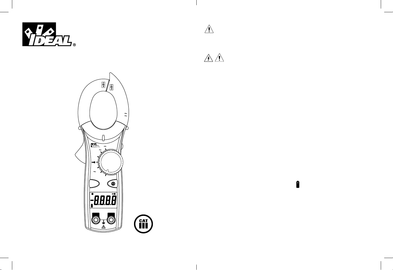
600 AAC Clamp Meter
Instruction Manual
CLAMP
CAT.III
V
61-746
V
Ω
40
A
600
OFF
NCV
True RMS
HOLD
APO
DC
KACmΩ V
COM
CAT.III
600V
V/Ω
#61-744
#61-746
Read First: Safety Information
Understand and follow operating instructions carefully. Use the meter, test leads
and all accessories only as specified in this manual; otherwise, the protection
provided by the meter can be impaired.
WARNING
To avoid possible electric shock, personal injury or death, follow these
guidelines:
• Do not use if meter appears damaged. Visually inspect the meter to ensure case
and jaws are not cracked.
• Inspect and replace test leads if insulation is damaged, metal is exposed, or
probes are cracked. Pay particular attention to the insulation surrounding the
connectors.
Register your product and access more information at www.idealindustries.com
•
600V
600A
To preserve the safety rating of this product, use only test leads with a minimum
rating of CAT III 600V. Do not use improvised connections that could present a safety
hazard.
• Note that the measurement category and voltage rating of combinations of
the meter, the test leads, and the accessories is the lowest of the individual
components.
• Do not use meter if it operates abnormally as protection maybe impaired.
• Do not use during electrical storms or in wet weather.
• Do not use around explosive gas, dust, vapor, amperage or in damp or wet
environments.
• Do not apply more than the rated voltage or amperage.
• Remove the test leads from the input jacks before measuring current.
• Replace battery as soon as battery indicator appears to avoid false readings.
• Remove the test leads from the meter prior to removing battery cover.
• Do not use without the battery and battery cover properly installed.
AM
• Do not attempt to repair this unit as it has no user-serviceable parts.
• Use the proper terminals, functions and range for your measurements.
• Never ground yourself when taking electrical measurements.
• Connect the black common lead to ground or neutral before applying the red test
lead to potential voltage. Disconnect the red test lead from the voltage first.
• Keep fingers behind the guard rings of the probe tips.
• Hold the clamp behind the tactile barrier.
Page 1
Page 2
Page 2
CAUTION
To protect yourself, think “Safety First”:
• Comply with local and national safety codes.
• Use appropriate personal protective equipment such as face shields, insulating
gloves, insulating boots, and/or insulating mats.
• Before each use:
- Perform a continuity test by touching the test leads together to verify the
functionality of the battery and test leads.
- Use the 3 Point Safety Method. (1) Verify meter operation by measuring a
known voltage. (2) Apply meter to circuit under test. (3) Return to the
known live voltage again to ensure proper operation.
• Always work with a partner.
Features:
• Auto/manual ranging clamp meter
• Non-Contact Voltage (70-600VAC)
• Measures 600 AAC Current
• Measures AC/DC Voltage and Resistance
• Audible continuity
• Data hold
• Auto Power Off
• Low Battery Indicator
• Compact jaws for reaching into tight spaces
• Electronic overload protection on all ranges
• 61-744 model is averaging sensing, rms calibrated
• 61-746 model is true rms sensing.
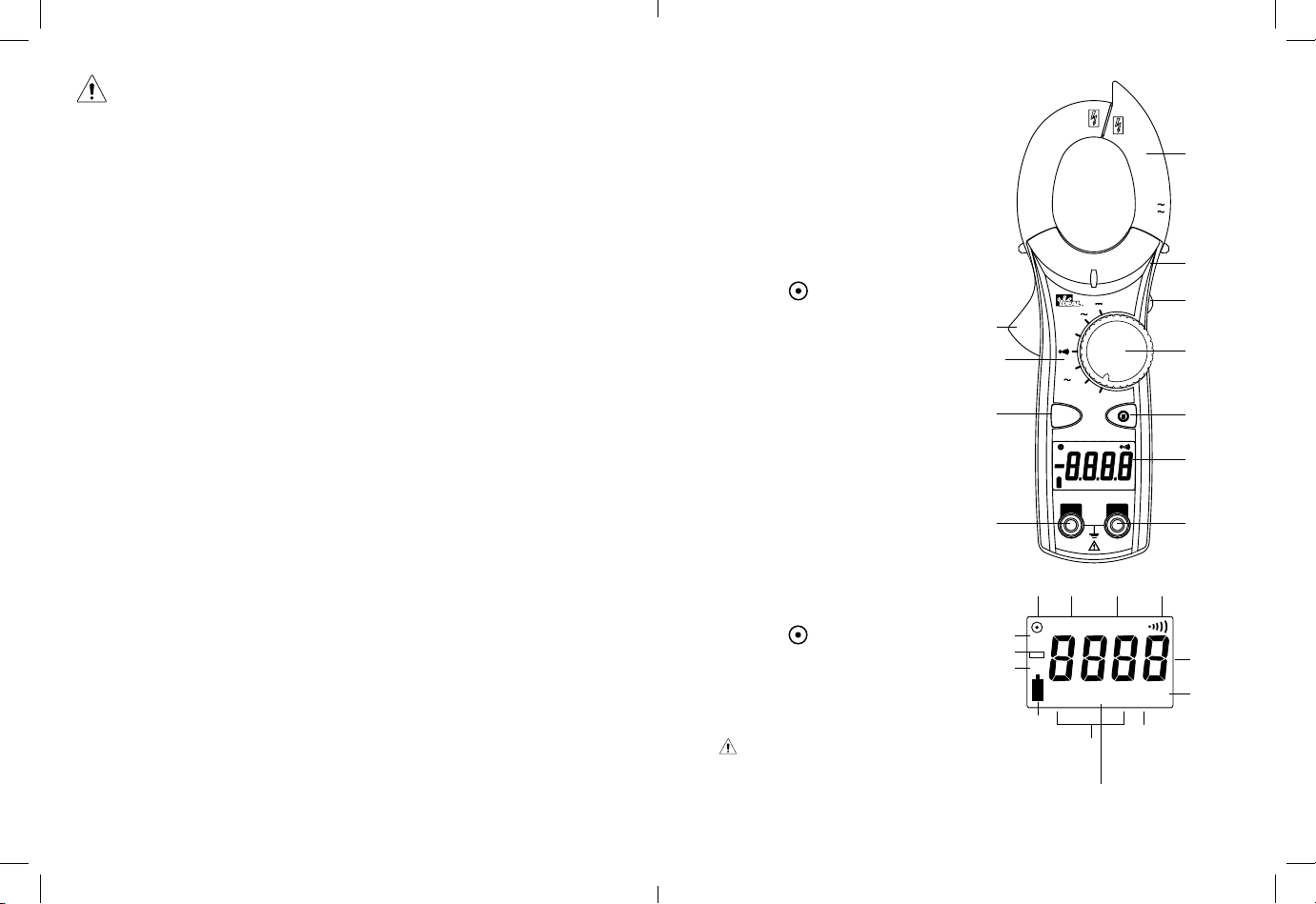
Features
1. Jaw Clamp
2. Lever
3. Function Dial
4. Display (LCD)
5. Volts and resistance (V-Ω)
input terminal
6. Common (COM) input terminal
7. Non-Contact Voltage (NCV)
8. Range ( )
9. Data Hold
10. Measuring Functions
11. Tactile Barrier
2
10
Display Icons
1. 4000 count display
2. Units of measure
7
3. Voltage
4. Amperes
5. Ohms
6. Continuity
6
7. AC measurement is selected
8. DC measurement is selected
9. Polarity indicator for DC
10. Low battery indicator
11. Range ( )
12. Data hold
13. APO - Auto Power Off
7
9
8
Symbols on the Unit
• Warning - read the instruction manual
• NCV - Non-Contact Voltage
• Cat III - 600V Safety category
CLAMP
CAT.III
V
61-746
V
Ω
40
A
600
OFF
NCV
True RMS
HOLD
DC
KACmΩ V
COM
CAT.III
600V
11 12 13
HOLD APO
AC
DC
K M Ω m VA
10
2
5
APO
1
600V
600A
11
9
3
8
4
AM
V/Ω
5
6
1
4
3
Page 3
Page 4
Page 3
Symbols on the Unit
Risk of Danger. Important Information. See Manual.
Hazardous voltage. Risk of electrical shock.
Application around and removal from Hazardous Live conductors is permitted.
~
CAT II
CAT III
CAT IV
AC (Alternating Current)
...
DC (Direct Current)
Earth Ground
Measurement Category II applies to test and measuring circuits connected directly to
utilization points (socket outlets and similar points) of the low-voltage installation
Measurement Category III applies to measuring circuits connected to the distribution
part of the building’s low-voltage installation
Measurement Category IV applies to test and measuring circuits connected at the
source of the building’s low-voltage installation
Auto/Manual Ranging Mode ( )
The meter defaults to autoranging mode when powered on. In this mode, the meter
automatically selects the best range to display the measurement. By pressing the
Range ( ) button on the meter, the manual range mode will override the autoranging feature of the meter. A ( ) appears in the upper left side of the display.
Continue pressing the Range button until the desired range is obtained. Use this
mode to lock in a specific range for repeated measurements. To return to the
autoranging mode, either depress the Range button for greater than 1 second or turn
the meter off and then back on again.
Data Hold Feature
Press the Hold button on the side of the meter to toggle in and out of the data hold
mode. “HOLD” appears in the upper left of the meter display when data hold is
active. Use the data hold feature to lock a measurement reading on the display.
Press the Hold button again to unlock the display and obtain a real-time reading.
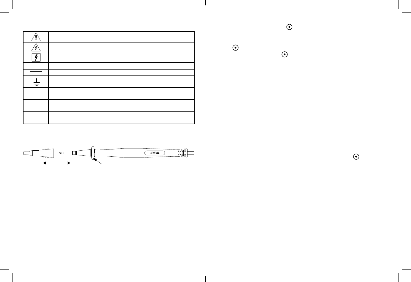
Test Leads
CAT IV 600V
CAT III 1000V
CAT II 1000V
Guard ring
OPERATION:
Non-contact voltage (NCV)
With the NCV tab on the tip of the clamp close to an AC voltage, press the NCV button. The NCV LED will light and the beeper will sound. The closer the NCV tab is to
AC voltage, the louder the beep. To differentiate between hot and neutral in an outlet,
insert the NCV tab into each slot in the outlet. The beeper will be much louder on
the hot side of the outlet than the neutral. The test lead can also be used to differentiate between the hot and neutral. Plug the red test lead into the V/Ω input jack on
the meter. Press the NCV button and insert the probe tip into each slot of the outlet.
The beeper will only beep on the hot side of the outlet.
Page 5
Auto Power Off (APO) Feature
The meter automatically powers itself down after about 10 minutes of no use. Press
any button, and the meter will wake up and display the last reading taken before
power down. This feature can be overridden by holding the Range ( ) button while
turning the function switch from Off to any other position. When APO is defeated,
the “APO” will be removed from the display. Turning the meter off will restore the
APO default.
Page 6
Page 4
V
Ω
V
40
A
600
600V
600A
61-746
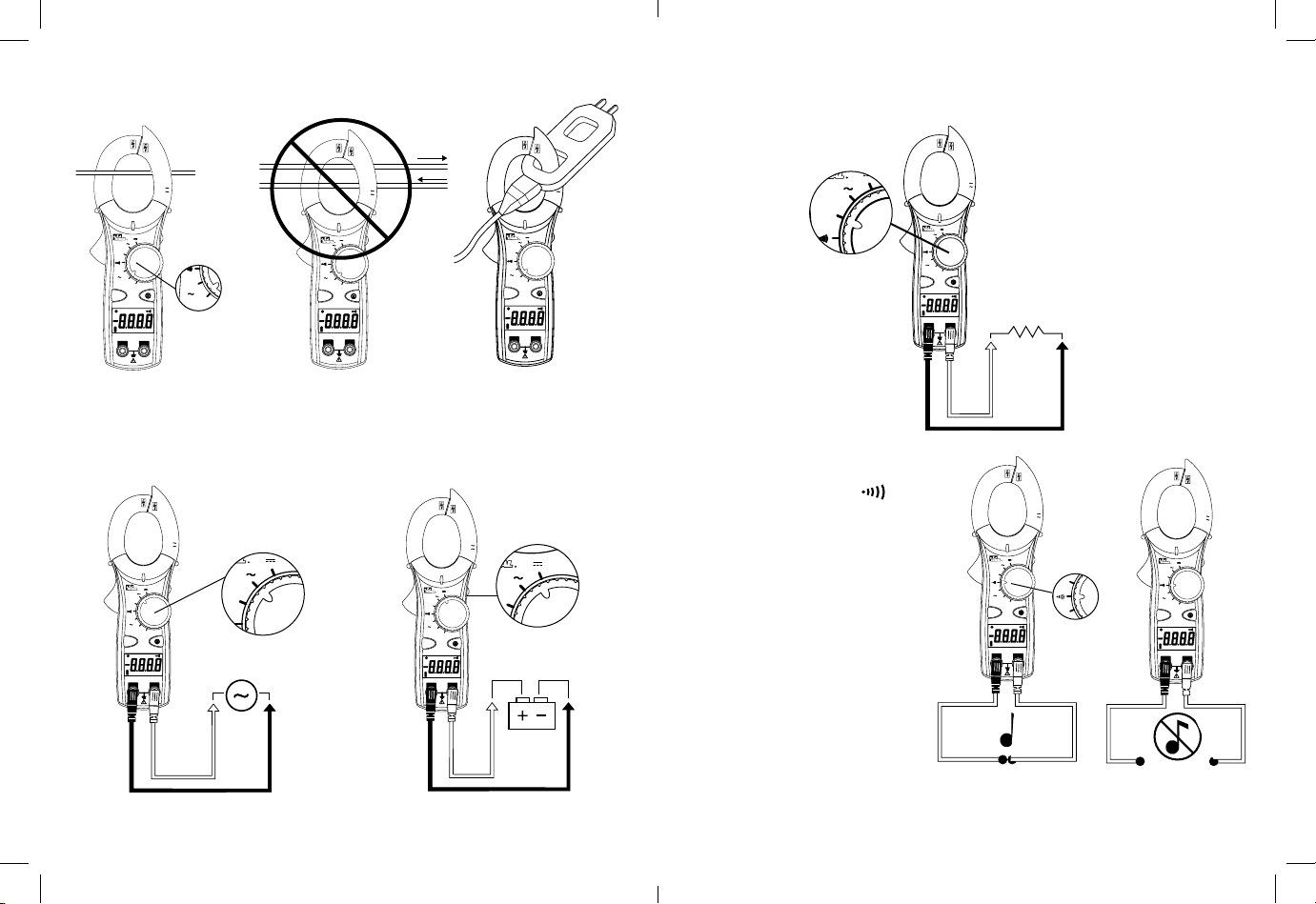
Measuring AC Current (Amps):
V
Ω
V
600V
600A
V
V
600V
600A
V
Ω
V
40
600V
600A
61-746
V
Ω
V
600V
600A
61-746
61-746
40
A
NCV
DC
V
Ω
600
OFF
True RMS
HOLD
KACmΩ V
COM
600V
600A
V
APO
AM
V/Ω
CAT.III
600V
CLAMP
CAT.III
Measuring Resistance (Ohms):
• Verify the circuit is de-energized to obtain accurate measurements.
H
600V
CLAMP
CAT.III
61-746
40
A
NCV
DC
V
Ω
600
OFF
True RMS
HOLD
KACmΩ V
COM
CAT.III
600V
600V
600A
V
APO
AM
V/Ω
CLAMP
CAT.III
61-746
40
A
NCV
DC
KACmΩ V
COM
600V
600A
N
V
V
Ω
600
OFF
True RMS
HOLD
APO
AM
V/Ω
CAT.III
600V
CLAMP
CAT.III
61-746
40
A
NCV
DC
COM
V
Ω
600
OFF
True RMS
HOLD
KACmΩ V
600A
V
APO
AM
V/Ω
CAT.III
600V
CORRECT
Single
Conductor
only
INCORRECT
Currents
cancel
CORRECT
Use with
line splitter
Measuring Voltage:
Verifying Continuity ( ):
600V
CLAMP
CAT.III
61-746
40
A
NCV
DC
COM
V
Ω
600
OFF
True RMS
HOLD
KACmΩ V
600A
V
APO
AM
V/Ω
CAT.III
600V
• Verify the circuit is de-energized.
600V
CLAMP
CAT.III
600A
V
61-746
V
Ω
40
A
600
OFF
NCV
True RMS
HOLD
APO
DC
AM
KACmΩ V
V/Ω
COM
CAT.III
600V
600V
CLAMP
CAT.III
600A
V
61-746
V
Ω
40
A
600
OFF
NCV
True RMS
HOLD
APO
DC
AM
KACmΩ V
V/Ω
COM
CAT.III
600V
• The meter will sense the level of
resistance and beep if the resistance
is less than 25Ω to confirm that
continuity is present.
Closed
AC Voltage DC Voltage
Page 7
Page 8
Circuit
CLAMP
CAT.III
V
61-746
V
Ω
40
A
600
OFF
NCV
True RMS
HOLD
APO
DC
KACmΩ V
COM
CAT.III
600V
Open
Circuit
600V
600A
AM
V/Ω
Page 5
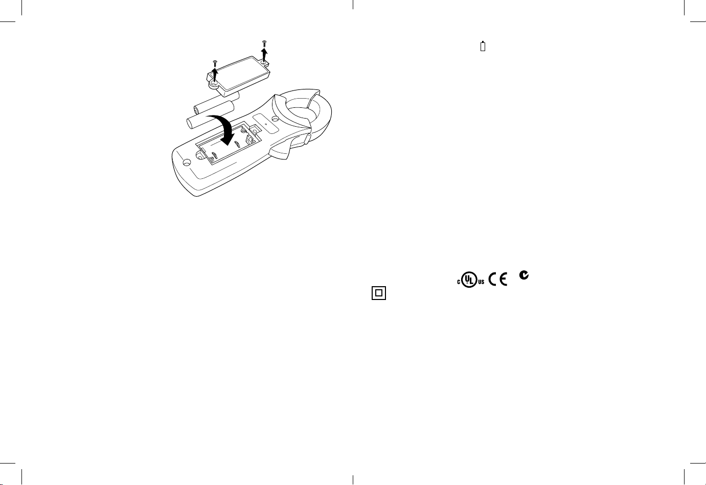
Battery Replacement:
• Ensure test leads are disconnected from
circuit or components.
• Remove test leads from input jacks
on meter.
• Remove the two screws from the
battery cap.
+
-
-
+
• Remove the battery cap.
• Replace batteries with two
“AAA” batteries.
• Assemble the battery cap
to the meter and re-tighten
the screws.
Maintenance:
Switch off and disconnect the meter completely before carrying out any maintenance.
Clean the case with a damp cloth and mild detergent. Do not use abrasives or solvents.
Keep away from liquids and ensure the meter is completely dry before use.
Service and Replacement Parts:
This unit has no user-serviceable parts.
For replacement parts or to inquire about service information contact IDEAL
INDUSTRIES, INC. at 1-877-201-9005 or visit our website www.idealindustries.com.
Specifications:
Display: 3-3/4 digit LCD with 4000 counts
Polarity: Automatic, positive implied, negative (-) polarity indication.
Overrange: “OL” indication is displayed.
Measure Rate: Samples 2 times per second, nominal.
Auto Power Off: Approximately after 10 minutes of non-use.
Battery Life: 400 hours continuous with Alkaline (61-744)
250 hours continuous with Alkaline (61-746)
Low Battery Indication: The “ “ is displayed when battery voltage drops below
+
operating level.
Power Supply: (2) 1.5V “AAA” batteries (NEDA R03).
Includes an isolated battery compartment.
Accuracy: Stated accuracy at 23°C ±5°C, <75% R.H.
Temperature 0.1 x (specified accuracy) per °C,
Coefficient: (0°C to 18°C, 28°C to 50°C).
Altitude: 6561.7 ft. (2000m)
Operating Environment: 32°F to 122°F (0°C to 50°C) at < 70% R.H.
Storage Environment: -4°F to 140°F (-20°C to 60°C) at < 80% R.H.
Jaw Opening: Accepts a 1.50” (38mm) conductor
Dimensions: 8.0”H x 2.6”W x 1.5”D (203mm H x65mm W x37mm D)
Weight: 7.1 oz (200g) including batteries
Accessories included: Carrying Case, Test Leads, (2) 1.5V “AAA” batteries,
operating instructions.
Safety: Complies with UL/IEC/EN: 61010-1, 61010-2-032,
61010-031 specifications, Cat III-600V.
N12966
Double Insulation
Instrument has been evaluated and complies with insulation category III (overvoltage
category III). Pollution degree 2 in accordance with IEC-644. Indoor use.
Ranges & Accuracies:
AC Converter:
61-744 model is averaging sensing, rms calibrated
61-746 model is true rms sensing.
Accuracy:
Accuracy is specified as +/-(a percentage of the reading + a fixed amount) at
23°C±5°C (73.4°F ± 9°F), less than 75% relative humidity.
Page 9
Page 10
Page 6
Temperature Coefficient: 0.1 times the applicable accuracy specification per
degree C from 0°C to 18°C and 28°C to 50°C (32°F to 64°F and 82°F to 122°F)
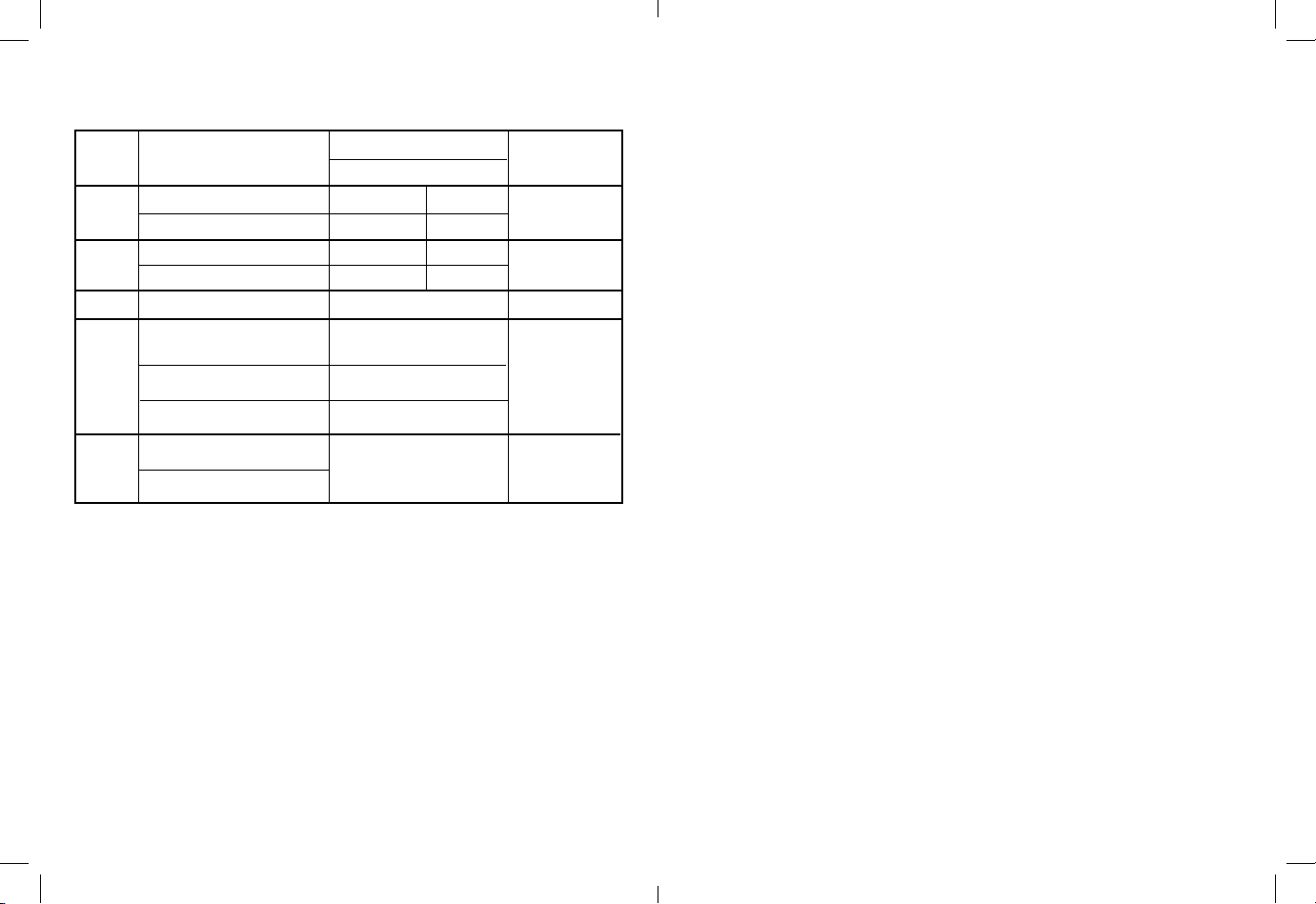
Function
AC Current*
40.00A//400.0A/600A (50Hz - 60Hz) 1.7% + 6 digits 1.7% + 10 digits
40.00A/400.0A/600A (60Hz - 400Hz) 3.0% + 6 digits 3.0% + 10 digits
400.0V (50Hz - 500Hz) 1.2% + 5 digits 1.2% + 8 digits
AC Voltage
600V (50Hz - 500Hz) 1.5% + 5 digits 1.5% + 8 digits
DC Voltage 400.0V/600V 0.5% + 2 digits 600 VDC or AC rms
400.0k Ω
Resistance
40.00MΩ 3.0% + 5 digits
Audible indication < 25Ω
Continuity
Response time: 500ms
Range and
Resolution
400.0Ω/4.000kΩ/40.00kΩ/
4.000MΩ 1.5% + 4 digits
61-744 61-746
Accuracy
600 VDC or AC rms
1.0% + 4 digits
600 VDC or AC rms
N/A 600 VDC or AC rms
Overload
Protection
600AAC
* Accuracy stated for crest factor ≤ 3
Input Impedance is 10MΩ.
Warranty Statement:
This tester is warranted to the original purchaser against defects in material and
workmanship for two years from the date of purchase. During this warranty period,
IDEAL INDUSTRIES, INC. will, at its option, replace or repair the defective unit,
subject to verification of the defect or malfunction.
This warranty does not cover fuses, batteries or damage from abuse, neglect, accident, unauthorized repair, alteration, or unreasonable use of the instrument.
Any implied warranties arising out of the sale of an IDEAL product, including but
not limited to implied warranties of merchantability and fitness for a particular
purpose, are limited to the above. The manufacturer shall not be liable for loss of
use of the instrument or other incidental or consequential damages, expenses, or
economic loss, or for any claim or claims for such damage, expenses or economic
loss.
State laws vary, so the above limitations or exclusions may not apply to you. This
warranty gives you specific legal rights, and you may also have other rights which
vary from state to state.
Page 11
Page 12
Page 7

#61-744
#61-746
Medidor de pinza
Manual de Instrucciones
APO
V/Ω
600V
600A
AM
CLAMP
CAT.III
V
61-746
V
Ω
40
A
600
OFF
NCV
True RMS
HOLD
DC
KACmΩ V
COM
CAT.III
600V
Registre su producto y acceda a más información en www.idealindustries.com
Lea Primero: Información de Seguridad
Entienda y siga las instrucciones de operación cuidadosamente. Use el multímetro, las
sondas y todos los accesorios únicamente como se especifica en este manual; de lo
contrario, la protección que proporciona el multímetro puede verse perjudicada.
ADVERTENCIA
Para evitar posibles riesgos de descarga eléctrica, lesiones o la muerte, siga estas
directrices:
• No use el multímetro si el mismo parece estar dañado. Inspecciónelo visualmente
para asegurarse de que la cubierta y la pinza no estén quebradas.
• Inspeccione y reemplace los cables si el aislamiento está dañado, hay metal expuesto
o las sondas están quebradas. Preste atención especial al aislante alrededor de los
conectores.
• Para mantener la clasificación de seguridad de este producto, use únicamente
cables de sonda con una clasificación mínima de CAT IV 600V No use conexiones
improvisadas que puedan presentar un riesgo de seguridad.
• Tome nota de que la categoría de medición y la clasificación de voltaje de
combinaciones del multímetro, la sondas y los accesorios es la más baja de los
componentes individuales.
• No use el multímetro si funciona en forma anormal, porque la protección puede estar
perjudicada.
• No use el multímetro durante tormentas eléctricas o en clima húmedo.
• No use el multímetro cerca de gas, polvo, vapor, amperaje explosivo o en ambientes
húmedos o mojados.
• No aplique voltajes superiores a las nominales al multímetro.
• Quite las sondas de los puertos de entrada antes de medir corriente.
• Reemplace la batería tan pronto aparezca el indicador de carga de batería baja, para
evitar las lecturas falsas.
• Retire las sondas del multímetro antes de quitar la tapa de la batería.
• No use el multímetro sin la batería, ni sin la tapa de la batería correctamente instalada.
• No intente reparar esta unidad ya que no tiene piezas reparables por el usuario.
• Use las terminales, funciones y rangos apropiados para sus medidas.
• No se conecte a tierra cuando tome medidas eléctricas.
• Conecte la sonda negra común a tierra o a neutro antes de tocar la sonda roja a
voltaje potencial. Desconecte la sonda roja del voltaje primero.
• Mantenga los dedos detrás de los anillos protectores en las puntas de las sondas.
• Mantenga el producto tras la barrera táctil.
• Los voltajes superiores a 30 VCA o 60 VCD representan un riesgo de descarga
eléctrica, así que tenga precaución.
Page 13
Page 14
Page 8

PRECAUCIÓN
Para protegerse, piense “¡La seguridad primero!”:
• Cumpla con los requisitos de seguridad locales y nacionales.
• Use equipos de protección personal apropiados, tales como, caretas, guantes aislantes,
calzado y/o alfombras aislantes.
• Antes de cada uso:
- Realice una prueba de continuidad poniendo en contacto las sondas para
verificar el funcionamiento de la batería y de las sondas.
- Use el Método de Seguridad de 3 Puntos. (1) Verifique el funcionamiento del
multímetro midiendo un voltaje conocido. (2) Aplique el multímetro al circuito
en prueba. (3) Vuelva al voltaje conectado conocido para asegurar el
funcionamiento correcto.
• Siempre trabaje con un compañero.
Características:
• Medidor de pinza con selección de gama automática y manual
• Indicaciones de valor eficaz (rms) real (Modelo 61-746 únicamente)
• Detección de voltaje sin contacto (70 a 600 V CA)
• Medida de corriente hasta 600 A CA
• Medida de voltaje de CA/CC y resistencia
• Verificación de continuidad con indicación audible
• Retención de datos
• Apagado automático
• Indicador de batería descargada
• Mordazas compactas, para penetrar en espacios estrechos
• Protección electrónica contra sobrecarga en todas las gamas
• El modelo 61-744 detecta valores promedio y está calibrado en valores eficaces
(rms).
• El modelo 61-746 detecta valores eficaces (rms) reales.
Page 15
Características
1. Sujeción con mordazas
2. Palanca
3. Selector de funciones
4. Pantalla de cristal líquido (LCD)
5. Terminal de entrada para voltaje y
resistencia (V-Ω)
6. Terminal de entrada común (COM)
7. Voltaje sin contacto (Non-Contact
Voltage - NCV)
8. Gama ( )
9. Retención de datos
10. Funciones de medida
11. Barrera táctil
Íconos de la pantalla
1. Pantalla de 4000 cuentas
2. Unidades de medida
3. volts
4. amperes
5. ohms
6. Continuidad
7. Está seleccionada la medida de CA
8. Está seleccionada la medida de CC
9. Indicador de polaridad para CC
10. Indicador de batería descargada:
11. Gama ( )
12. Retención de datos
13. Apagado automático (Auto Power
Off – APO)
Símbolos de la unidad
• Advertencia: lea el manual de
instrucciones
• NCV (Non-Contact Voltage): Voltaje sin
contacto
• Cat III: Categoría de seguridad 600 V
Page 16
2
10
7
6
11 12 13
7
AC
9
DC
8
10
CLAMP
CAT.III
V
61-746
V
Ω
40
A
600
OFF
NCV
True RMS
HOLD
APO
DC
KACmΩ V
V/Ω
COM
CAT.III
600V
HOLD APO
K M Ω m VA
3
2
5
1
600V
600A
11
9
3
8
4
AM
5
6
1
4
Page 9

Symbols on the Unit
Riesgo. Información Importante. Vea el Manual.
Voltaje peligroso. Peligro de choque eléctro.
Se permite la aplicación y el retiro de alrededor y de Conductores Energizados.
~
CAT II
CAT III
CAT IV
CA (Corriente Alterna)
...
CD (Corriente Directa)
Tierra
Categoría de Medición II aplica a la prueba y medición de circuitos directamente conectados a puntos de utilización (tomacorrientes y puntos similares) de la instalación
de la red eléctrica de bajo voltaje
Categoría de Medición III aplica a la medición de circuitos conectados a la parte de
distribución de la instalación de la red eléctrica de bajo voltaje del edificio
Categoría de Medición IV aplica a la prueba y medición de circuitos conectados a la
fuente de la instalación de la red eléctrica de bajo voltaje del edificio
Sondas
CAT IV 600V
CAT III 1000V
CAT II 1000V
Anillo Protector
OPERACIÓN:
Voltaje sin contacto (Non-Contact Voltage - NCV)
Manteniendo la lengüeta NCV de la punta de la pinza cerca de un voltaje de CA, presione el botón NCV. El LED NCV se encenderá, y el emisor de pitidos sonará. Cuanto
más se aproxime la lengüeta NCV al voltaje de CA, más fuerte será el pitido. Para distinguir entre el ‘vivo’ y el neutro de un tomacorriente, introduzca la lengüeta NCV en
cada una de sus ranuras. El pitido será mucho más fuerte en el lado ‘vivo’ del tomacorriente que en el neutro. El cable de prueba puede utilizarse también para distinguir
entre el ‘vivo’ y el neutro. Enchufe el cable de prueba rojo en la entrada ‘VΩ’. Presione
el botón NCV, e inserte la punta de la sonda en cada ranura del tomacorriente. El
emisor de pitidos sonará únicamente en el lado ‘vivo’ del tomacorriente.
Modo de selección de gama automático/manual ( )
El medidor, al encenderse, va por defecto al modo de selección automática de gama.
En este modo, el medidor selecciona automáticamente la mejor gama para indicar la
medida. Al presionar el botón Range (Gama) ( ) del medidor, el modo de selección manual de gama prevalecerá sobre la función de selección automática de gama
del medidor. En el lado superior izquierdo de la pantalla aparece un ( ). Continúe
presionando el botón Range (Gama) hasta llegar a la gama deseada. Utilice este
modo para mantener fija una gama específica cuando deba hacer medidas repetidas.
Para volver al modo de selección automática de gama, puede mantener presionado
el botón Range (Gama) durante más de 1 segundo, o apagar el medidor y encenderlo
nuevamente.
Característica de retención de datos
Presione el botón Hold (Retención), ubicado en el costado del medidor, para entrar y
salir sucesivamente del modo de retención de datos. Cuando la función de retención
de datos está activa, aparece en la parte superior izquierda de la pantalla del medidor
la leyenda ‘HOLD’ (RETENCIÓN). Utilice la característica de retención de datos para
fijar una lectura de medida en la pantalla. Para que la indicación de la pantalla deje
de estar fija, y pueda obtenerse una lectura en tiempo real, vuelva a presionar el
botón Hold (Retención).
Característica de apagado automático (Auto Power Off – APO)
El medidor se desactiva automáticamente después de 10 minutos sin uso. Si en
esa situación presiona cualquier botón, el medidor se reactivará e indicará en su
pantalla la última lectura tomada antes de desactivarse. Esta característica puede
ser anulada manteniendo presionado el botón Range (Gama) ( ) mientras se hace
girar el conmutador de funciones desde la posición OFF (APAGADO) hasta cualquier
otra. Cuando se anula el apagado automático, la leyenda ‘APO’ desaparecerá de la
pantalla. Al apagar el medidor, se restaurará la característica de apagado automático
por defecto.
Page 17
Page 18
Page 10

Medida de corriente alterna (CA) (amperes):
V
Ω
V
40
A
600
600V
600A
61-746
V
Ω
V
600V
600A
V
V
600V
600A
V
Ω
V
600V
600A
61-746
V
Ω
V
40
600V
600A
61-746
61-746
Ω
40
A
NCV
DC
KACmΩ V
COM
600V
600A
V
V
600
OFF
True RMS
HOLD
APO
AM
V/Ω
CAT.III
600V
CLAMP
CAT.III
61-746
Ω
40
A
NCV
DC
KACmΩ V
COM
600V
600A
V
V
600
OFF
True RMS
HOLD
APO
AM
V/Ω
CAT.III
600V
CLAMP
CAT.III
Medida de resistencia (ohms):
• Para obtener medidas precisas, verifique que el circuito esté desenergizado.
H
600V
CLAMP
CAT.III
61-746
Ω
40
A
NCV
DC
KACmΩ V
COM
600V
600A
V
V
600
OFF
True RMS
HOLD
APO
AM
V/Ω
CAT.III
600V
CLAMP
N
CAT.III
61-746
40
A
NCV
DC
COM
V
Ω
600
OFF
True RMS
HOLD
KACmΩ V
600A
V
APO
AM
V/Ω
CAT.III
600V
CORRECTO
Sólo un
conductor
INCORRECTO
Las corrientes
se anulan
CORRECTO
Uso con divi-
sor de línea
único
Medida de voltaje:
Verificación de continuidad ( ):
• Verifique que el circuito esté
600V
CLAMP
CAT.III
61-746
40
A
NCV
DC
COM
V
Ω
600
OFF
True RMS
HOLD
KACmΩ V
600A
V
APO
AM
V/Ω
CAT.III
600V
desenergizado.
600V
CLAMP
CAT.III
600A
V
61-746
V
Ω
40
A
600
OFF
NCV
True RMS
HOLD
APO
DC
AM
KACmΩ V
V/Ω
COM
CAT.III
600V
600V
CLAMP
CAT.III
600A
V
61-746
V
Ω
40
A
600
OFF
NCV
True RMS
HOLD
APO
DC
AM
KACmΩ V
V/Ω
COM
CAT.III
600V
• El medidor detectará el nivel de
resistencia y emitirá un pitido si
la resistencia es menor que 25 Ω,
para confirmar que existe continuidad.
Circuito
Voltaje de CA Voltaje de CC
Page 19
Page 20
cerrado
interrumpido
CLAMP
CAT.III
61-746
Ω
40
A
600
NCV
HOLD
DC
KACmΩ V
COM
Circuito
True RMS
600V
600A
V
V
OFF
APO
AM
V/Ω
CAT.III
600V
Page 11

MANTENIMIENTO
Reemplazo de las baterías:
• Asegúrese de que los cables de prueba estén
desconectados del circuito o de los componentes.
• Retire los cables de prueba de los conectores
hembra (jacks) de entrada del medidor.
-
+
+
-
• Quite los dos tornillos de la tapa de las baterías.
• Retire la tapa de las baterías.
• Reemplace las baterías por dos baterías ‘AAA’.
• Monte la tapa de las baterías en
el medidor, y vuelva a apretar los tornillos.
Mantenimiento:
Apague y desconecte completamente el medidor antes de llevar a cabo cualquier
mantenimiento. Limpie el estuche con un paño húmedo y un detergente suave
No use abrasivos o solventes. Mantenga alejado de líquidos y asegúrese de que
el medidor esté completamente seco antes de usarlo.
Piezas de servicio y de repuesto:
Esta unidad no contiene piezas reparables por el usuario. Di necesita piezas
de repuesto o averiguar sobre información de servicio, contacte con IDEAL
INDUSTRIES, INC., llamando al 1-877-201-9005, o visite nuestro sitio Web
www.testersandmeters.com.
Especificaciones:
Pantalla: Pantalla de cristal líquido (LCD) de 3-3/4 dígitos, 4000
cuentas
Polaridad: Automática, positiva implícita, indicación de polaridad
negativa (-).
Fuera de gama: Se indica en la pantalla ‘OL’.
Frecuencia de medición: 2 muestras por segundo (nominal).
Apagado automático Después de aproximadamente 10 minutos sin uso.
(Auto Power Off – APO):
Vida de las baterías: 400 horas continuas, con baterías alcalinas (61-744)
250 horas continuas, con baterías alcalinas (61-746)
Indicación de batería Se indica en la pantalla ‘ ‘ cuando el voltaje de la batería
+
descargada cae por debajo del nivel de operación.
Page 21
Fuente de alimentación (2) Baterías ‘AAA’ de 1,5 V (NEDA R03). Incluye un
compartimiento para batería aislado.
Precisión: Precisión especificada a 23°C ± 5°C, humedad relativa
< 75 %.
Coeficiente de 0,1 x (precisión especificada) por °C (0°C a 18°C,
temperatura: 28°C a 50°C)
Altitud: 2000 m (6561,7 pies)
Ambiente de operación: 0°C a 50°C (32°F a 122°F), humedad relativa < 70 %.
Ambiente de -20°C a 60°C (-4°F a 140°F), humedad relativa < 80%.
almacenamiento:
Abertura de la mordaza: Acepta un conductor de 38 mm (1,50”)
Dimensiones: 203 mm [altura] x 65 mm [ancho] x 37 mm [prof.]
(8,0” [altura] x 2,6” [ancho] x 1,5” [prof.]
Peso: 200 g (7,1 onzas) incluyendo baterías
Accesorios incluidos: Estuche portátil, Cables de prueba, (2) baterías ‘AAA’ de
1,5 A, instrucciones de operación.
Seguridad: Cumple con las especificaciones UL/IEC/EN: 61010-1,
61010-2-032, 61010-031. Cat III-600V.
N12966
Aislamiento doble
El instrumento ha sido evaluado, y cumple con la categoría III de aislamiento
(categoría III de sobrevoltaje). Grado 2 de contaminación, de acuerdo con
IEC-644. Uso en interiores.
Page 22
Page 12

Gamas y precisiones:
Convertidor de CA:
El modelo 61-744 detecta valores promedio y está calibrado en valores eficaces
(rms).
El modelo 61-746 detecta valores eficaces (rms) reales.
Precisión:
La precisión se especifica como ± (un porcentaje de la lectura + una cantidad
fija) a 23°C ± 5°C (73,4°F ± 9°F), y una humedad relativa menor que 75 %.
Coeficiente de temperatura: 0,1 veces la especificación aplicable de precisión por grado C, desde 0°C hasta 18°C y desde 28°C hasta 50°C (32°F a
64°F, y 82°F a 122°F)
Función
Corriente * 40,00A/400,0A/600A (50Hz - 60Hz) 1,7% + 6 dígitos 1.7% + 10 dígitos
alterna (CA) 40,00A/400,0/600A (60Hz - 400Hz) 3,0% + 6 dígitos 3.0% + 10 dígitos
400,0V (50Hz - 500Hz) 1,2% + 5 dígitos 1.2% + 8 dígitos
Voltaje de
CA 600V (50Hz - 500Hz) 1,5% + 5 dígitos 1.5% + 8 dígitos
Gama y Protección contra
resolución
Precisión
61-744 61-746
sobrecarga
600A CA
600 V CA/CC rms
Garantía:
Se garantiza al comprador original del medidor contra los defectos de material y
mano de obra durante la vida útil del producto. Durante este período de garantía,
IDEAL INDUSTRIES, INC. podrá, a su elección, reemplazar o reparar la unidad
defectuosa, sujeta a verificación del defecto o falla. Esta garantía no se aplica a
defectos resultantes del mal uso, negligencia, accidente, reparación no
autorizada, alteración o uso irracional de este instrumento.
Cualquier garantía implícita originada en la venta de un producto IDEAL,
incluyendo -pero sin limitarse a ellas- garantías implícitas de comerciabilidad y
adecuación para un propósito particular, se limitan a lo indicado anteriormente.
El fabricante no será responsable por la pérdida del uso del instrumento u otros
daños emergentes o concomitantes, gastos o pérdida económica, o por cualquier
reclamación de dichos daños, gastos o pérdidas económicas.
Las leyes estatales varían, por lo que las limitaciones o exclusiones anteriores
pueden no aplicarse en su caso. Esta garantía le da derechos legales específicos,
y usted puede tener también otros derechos que varían de estado a estado.
Voltaje de CC
400,0k Ω
Resistencia
40,00MΩ 3,0% + 5 dígitos
Continuidad
Response time: 500ms
400,0V/600V 0,5% + 2 dígitos
400,0Ω/4,000kΩ/40,00kΩ/
4,000MΩ 1,5% + 4 dígitos
Audible indication < 25Ω
1,0% + 4 dígitos
Sin especificación 600 V CA/CC rms
*Precisión especificada para factor de cresta < 3 a plena escala
Impedancia de entrada: 1OMΩ.
600 V CA/CC rms
600 V CA/CC rms
Page 23
Page 24
Page 13

#61-744
#61-746
Multimètre à pince
Mode d’emploi
CLAMP
CAT.III
61-746
V
Ω
40
A
600
OFF
NCV
True RMS
HOLD
DC
KACmΩ V
COM
CAT.III
600V
V
Enregistrez votre produit et accédez à davantage d’informations sue
www.idealindustries.com
Lire en premier : Informations de sécurité
Assimiler et se conformer scrupuleusement aux instructions d’utilisation.
N’utiliser le multimètre que de la façon spécifiée dans le présent manuel ; à
défaut, la protection offerte par le multimètre pourra être compromise.
APO
V/Ω
600V
600A
AM
Page 25
AVERTISSEMENT
Pour éviter tout risque d’électrocution, de lésions personnelles ou de mort, se
conformer aux directives suivantes :
• Ne pas utiliser le multimètre s’il paraît endommagé. Examiner le multimètre pour
s’assurer que son boîtier et sa pince ne sont pas fissurés
• Inspectez et remplacez les cordons si leur isolation est endommagée, le métal exposé
ou les sondes craquelées. Porter une attention particulière à l’isolant entourant les
connecteurs.
• Afin de maintenir la classification de sécurité de ce produit, utilisez exclusivement des
conducteurs d’essai classés CAT IV 600 V. Vous ne devez pas avoir recours à des
connexions improvisées susceptibles de présenter un risque pour le sécurité.
• Noter que la catégorie de mesure et la classification de tension des combinaisons des
conducteurs d’essai et des accessoires est le plus bas des composants individuels.
• Ne pas utiliser le multimètre s’il fonctionne de manière anormale, la protection qu’il
offre pouvant être compromise.
• Ne pas utiliser l’appareil pendant des orages ou par temps très humide.
• Ne pas utiliser l’appareil en présence de gaz, poussière, vapeur ou ampérage explosifs
ou dans des milieux humides ou riches en eau.
• Ne pas soumettre le multimètre à une tension supérieure à la tension nominale.
• Retirer les conducteurs d’essai des conducteurs d’essai ses prises avant de mesurer le
courant.
• Remplacer la pile dès que le témoin de pile est affiché afin d’éviter les fausses lectures.
• Retirer les fils d’essai du circuit avant de retirer le capuchon de pile.
• Ne pas utiliser sans la pile ou si l’arrière du boîtier n’est pas bien monté.
• Ne pas tenter de réparer cet appareil. Il ne comporte aucune pièce réparable par
l’utilisateur.
• Utiliser les bonnes bornes, fonctions et plage pour vos mesures.
• Ne jamais se mettre à la terre quand on procède à des mesures électriques.
•
Connecter le conducteur commun noir à la terre ou au neutre avant d’appliquer le
conducteur d’essai rouge sur la tension potentielle. Commencer par déconnecter le fil
d’essai rouge de la tension.
• Placer les doigts doivent demeurer derrière les bagues de protection des pointes de
sonde.
• Maintenir l’appareil hors de portée.
• Les tensions dépassant 30 V CA ou 60 V CC peuvent présenter un risque
d’électrocution, il faut donc faire preuve de prudence.
Page 26
Page 14

ATTENTION
Pour vous protéger, ayez le réflexe « la sécurité d’abord ».
• Observez les codes de sécurité locaux et nationaux.
• Utiliser un équipement de protection individuelle approprié, comme lunettes de
sécurité, masque facial, gants isolants, chaussures isolées, et/ou tapis isolants.
• Avant chaque utilisation :
- Procéder à un essai de continuité et mettant les fils d’essai en contact l’un avec
l’autre afin de contrôler le fonctionnement de la pile et des fils d’essai.
- Utiliser la méthode de sécurité en 3 points. (1) Vérifier le fonctionnement du
multimètre en mesurant une tension connue. (2) Appliquer le multimètre au
circuit en cours de contrôle. (3) Retourner à la tension active connue pour
vérifier le bon fonctionnement.
• Travailler toujours avec un équipier.
Caractéristiques :
• Multimètre à pince à sélection de plages automatique/manuelle
• Valeurs efficaces réelles (modèle 61-746 seulement)
• Détection de tension sans contact (70 à 600 V c.a.)
• Mesure le courant de 600 A c.a.
• Mesure la tension c.a./c.c. et la résistance
• Continuité audible
• Rétention de données
• Arrêt automatique
• Indicateur d’épuisement de piles
• Mâchoires de faible encombrement permettant de travailler dans des espaces
restreints
• Protection électronique contre la surcharge sur toutes les plages
• Le modèle 61-744 assure une détection par calcul de moyenne, le modèle
61-746 étalonné avec des valeurs efficaces réelles assure une véritable détec-
tion avec des valeurs efficaces réelles.
Caractéristiques
1. Pince mâchoire
2. Levier
3. Cadran des fonctions
4. Affichage (cristaux liquides)
5. Terminal d’entrée tension et
résistance (V-Ω)
6. Terminal d’entrée commun (COM)
7. Détection de tension sans contact
(NCV)
8. Plage ( )
9. Rétention de données
10. Fonctions de mesure
11. Hors de portée
Icônes d’affichage
1. Affichage jusqu’à 4000
2. Unités de mesure
3. Tension
4. Ampères
5. Ohms
6. Continuité
7. Mesure de c.a. est sélectionnée
8. Mesure de c.c. est sélectionnée
9. Témoin de polarité pour c.c.
10. Témoin de décharge de la pile
11. Plage ( )
12. Rétention de données
13. Arrêt automatique de l’alimentation
(AAA)
Symboles figurant sur l’appareil
• Avertissement – lire le mode
d’emploi
• Détection de tension sans contact NCV)
• Cat III – Catégorie de sécurité 600 V
CLAMP
2
10
7
6
7
9
8
CAT.III
V
61-746
V
Ω
40
A
600
OFF
NCV
True RMS
HOLD
APO
DC
KACmΩ V
COM
CAT.III
600V
11 12 13
HOLD APO
AC
DC
K M Ω m VA
10
2
5
1
600V
600A
11
9
3
8
4
AM
V/Ω
5
6
1
4
3
Page 27
Page 28
Page 15

Symboles figurant sur l’appareil
Risque de danger : Renseigments importants. Voir manuel.
Tension dangereuse. Risque d’électrocution.
L’application autour et le retrait des conducteurs sous tension dangereux sont permis.
~
CAT II
CAT III
CAT IV
CA (courant alternatif)
...
CC (courant continu)
Terre
La catégorie de mesure II s’applique à l’essai et à la mesure de circuits connectés
directement aux points d’utilisation (prises et points semblables) d’installation de
secteur à basse tension.
La catégorie de mesure III s’applique à la mesure de circuits connectés à la partie
distribution de l’installation de secteur à basse tension du bâtiment.
La catégorie de mesure IV s’applique à l’essai et à la mesure de circuits connectés à la
source de l’installation de secteur à basse tension de l’édifice.
Conducteurs d’essai
CAT IV 600V
CAT III 1000V
CAT II 1000V
Bague de protection
Sélection automatique/manuelle de plage ( )
Le multimètre se met sur le mode de sélection automatique de plage quand on
l’allume. Sur ce mode, le multimètre sélectionne la meilleure plage d’affichage de
la mesure. Lorsqu’on appuie sur le bouton de Plage ( ) du multimètre, le mode
de sélection manuelle de plage neutralisera la fonction de sélection automatique
de plage du multimètre. Un ( ) est affiché dans le coin supérieur gauche de
l’affichage. Continuer à appuyer sur le bouton de plage (Range) jusqu’à ce qu’on
obtienne la plage désirée. Utiliser ce mode pour verrouiller une plage particulière
afin de procéder à des mesures répétées. Pour retourner sur le mode de sélection
automatique de plage, appuyer sur le bouton Range (plage) pendant plus d’une
seconde ou éteindre le multimètre et le rallumer.
Fonction de rétention des données
Appuyer sur le bouton Hold (rétention) situé sur le côté du multimètre pour
basculer dans et hors du mode de rétention des données. « HOLD » est affiché
dans le coin supérieur gauche de l’affichage du multimètre quand la fonction de
rétention des données est active. Utiliser la fonction de rétention des données
pour verrouiller une lecture de mesure sur l’affichage. Appuyer à nouveau sur le
bouton Hold (Rétention) pour déverrouiller l’affichage pour obtenir une lecture en
temps réel.
FONCTIONNEMENT :
Détection de tension sans contact (TSC)
En veillant à ce que l’onglet NCV du bout de la pince soit près d’une tension
c.a., appuyer sur le bouton NCV. La DEL NCV s’allumera et l’avertisseur sonore
se déclenchera. Plus le capteur NCV est proche de la tension alternative et plus
le bip est fort. Pour différencier le fil sous tension du fil neutre dans une prise,
introduire l’onglet NCV dans chaque fente de la prise. Le bip sera plus fort du
côté sous tension que du côté neutre de la prise. Le fil d’essai rouge peut également être utilisé pour différencier le fil sous tension du fil neutre. Mettre le fil
d’essai rouge dans l’entrée VΩ. Appuyer sur le bouton NCV et introduire la
pointe de la sonde dans chacun des trous de la prise. L’avertisseur sonore ne se
déclenchera que du côté sous tension de la prise.
Page 29
Fonction Arrêt automatique de l’alimentation (APO)
Ce multimètre s’éteint automatiquement au bout de 10 minutes s’il n’est pas utilisé. Appuyer sur n’importe quel bouton, le multimètre s’allume automatiquement et
affiche la dernière lecture relevée. On peut neutraliser cette fonction en appuyant
sur le bouton Range ( ) tout en tournant le bouton des fonctions de la position
d’arrêt (Off) à nimporte quelle autre position. Quand AP0 est neutralisé, « APO »
disparaît de l’affichage. Quand on éteint le multimètre, on restaure l’APO (coupure
automatique) implicite.
Page 30
Page 16

Mesure du courant C.A. (Ampères) :
V
Ω
V
40
A
600
600V
600A
61-746
V
Ω
V
600V
600A
V
V
600V
600A
V
Ω
V
600V
600A
61-746
V
Ω
V
40
600V
600A
61-746
Mesure de la résistance (Ohms) :
• Vérifier que le circuit est désexcité pour obtenir des mesures précises.
H
61-746
Ω
40
A
600
NCV
HOLD
DC
KACmΩ V
COM
V
True RMS
600V
600A
V
OFF
APO
AM
V/Ω
CAT.III
600V
CLAMP
CAT.III
CORRECT
Conducteur
unique
seulement
Mesure de la tension :
600V
CLAMP
CAT.III
600A
V
61-746
V
Ω
40
A
600
OFF
NCV
True RMS
HOLD
APO
DC
AM
KACmΩ V
V/Ω
COM
CAT.III
600V
61-746
Ω
40
A
600
NCV
HOLD
DC
KACmΩ V
COM
V
True RMS
600V
600A
V
OFF
APO
AM
V/Ω
CAT.III
600V
CLAMP
CAT.III
INCORRECT
Les courants
s’annulent
61-746
40
A
NCV
DC
V
Ω
600
OFF
True RMS
HOLD
KACmΩ V
COM
CAT.III
600V
600A
V
APO
AM
V/Ω
600V
600V
CLAMP
CAT.III
600A
V
61-746
V
Ω
40
A
600
OFF
NCV
True RMS
HOLD
APO
DC
AM
KACmΩ V
COM
V/Ω
CAT.III
600V
CLAMP
N
CAT.III
CORRECT
Utilisation
avec répartition de ligne
Vérification de la continuité ( ) :
• Vérifier que le circuit est désexcité.
600V
CLAMP
CAT.III
61-746
40
A
NCV
DC
COM
V
Ω
600
OFF
True RMS
HOLD
KACmΩ V
600A
V
APO
AM
V/Ω
CAT.III
600V
• Le multimètre détectera le niveau de
600V
CLAMP
CAT.III
600A
résistance et émettra un signal
sonore si la résistance est inférieure
61-746
A
NCV
DC
V
Ω
40
600
OFF
True RMS
HOLD
KACmΩ V
COM
V
APO
AM
V/Ω
CAT.III
600V
à 25Ω pour confirmer la présence
d’une continuité.
600V
CLAMP
CAT.III
600A
V
61-746
V
Ω
40
A
600
OFF
NCV
True RMS
HOLD
APO
DC
AM
KACmΩ V
COM
V/Ω
CAT.III
600V
Circuit
Tension c. a. Tension c. c.
Page 31
Page 32
fermé
Circuit
ouvert
Page 17

ENTRETIEN
Remplacement de la pile :
• S’assurer que les fils d’essai sont déconnectés
du circuit ou des composants.
• Retirer les fils d’essai des prises d’entrée
-
+
+
-
du multimètre.
• Retirer les deux vis du capuchon de piles.
• Retirer le capuchon de piles.
• Remplacer les piles par deux piles « AAA ».
• Monter le capuchon des piles sur le
multimètre et resserrer les vis.
Entretien :
Éteignez et déconnectez complètement l’instrument avant de procéder à toute
intervention d’entretien. Nettoyez le boîtier avec un chiffon humide et un détergent doux. N’utilisez pas d’abrasifs ou de solvants. Tenez à l’écart des liquides et
assurez-vous que l’appareil est complètement sec avant de l’utiliser.
Entretien-dépannage et pièces de rechange :
Cet appareil ne comporte pas de pièces réparables par l’utilisateur.
En se ce qui concerne les pièces de rechange ou les renseignements concernant
l’entretien-dépannage, se mettre en rapport avec IDEAL INDUSTRIES, INC. Au
1-877-201-9005 ou visitez notre site web www.testersandmeters.com
Fiche technique :
Affichage : Affichage à cristaux liquides à 3-3/4 chiffres avec décompte
jusqu‘à 4000
Polarité : Indication de polarité automatique, positif implicite, négatif (-).
Dépassement : L’indication « OL » est affichée.
Fréquence de 2 échantillonnages par minute, nominal.
mesure :
Arrêt automatique : Au bout de 10 minutes de non-utilisation.
Durée de service 400 heures d’utilisation en continu avec une pile alcaline (61-744)
de la pile : 250 heures d’utilisation en continu avec une pile alcaline (61-746)
Témoin de Le « » est affiché quand la tension de la pile tombe
décharge de piles: au-dessous du niveau opérationnel.
+
Page 33
Alimentation : (2) pilles « AAA » de 1,5 V (NEDA R03).
Comprend un logement de piles isolé.
Précision : Précision nominale à 23°C ±%5°C, < 75 % H.R.
Coefficient de 0,1 x (précision spécifiée) par °C, (0°C à 18 °C, 28°C à 50°C).
température :
Altitude : 6561,7 pi (2000 m)
Environnement 32°F à 122°F (0° C à 50°C) à < 70 % d’H.R.
opérationnel :
Environnement de -4°F à 140°F (-20° C à 60°C) à < 80 % d’H.R.
stockage :
Ouverture de la Accepte un fil de 1,50 po (38 mm)
mâchoire :
Dimensions : 8,0 po L x 2,6 po l x 1,5 po H (203 mm L x 65 mm l x 37 mm H)
Poids : 7,1 oz (200 g) piles y compris
Accessoires Etui de transport, fils d’essais, 9@0 piles « AAA » de 1,5 V ,
Inclus : mode d’emploi.
Sécurité : Conforme aux normes UL/IEC/EN: 61010-1,
61010-2-032, 61010-031. Cat III-600V.
N12966
Double isolation
L’appareil a été évalué et il est conforme à la catégorie d’isolation III (catégorie de surtension III). Degré de pollution 2 conforme à la norme IEC-644. Pour une utilisation à
l’intérieur.
Page 34
Page 18

Plages et précisions :
Convertisseur c.a. :
Le modèle 61-744 assure une détection par calcul de moyenne, le modèle 61-746
étalonné avec des valeurs efficaces réelles assure une véritable détection avec des
valeurs efficaces réelles.
Précision :
La précision est spécifiée sous la forme d’un +/- (pourcentage de la lecture + une
quantité fixe) à 23°C±5°C (73.4°F ± 9°F), moins de 75 % d’humidité relative.
Coefficient de température : 0,1 fois la spécification de précision applicable par
degré C de 0°C à 18°C et 28°C à 50°C (32°F à 64°F et 82°F à 122°F)
Fonction Plage et contre
résolution 61-744 61-746 la surcharge
c.a. 600V (50Hz - 500Hz) 1,5% + 5 chiffres 1.5% + 8 chiffres
Tension c.c. 400,0V/600V 0,5% + 2 chiffres
400,0Ω/4,000kΩ/40,00kΩ/ 1,0% + 4 chiffres
400,0k Ω
Résistance
40,00MΩ 3,0% + 5 chiffres
40,00A/400,0A/600A (50Hz - 60Hz) 1,7% + 6 chiffres 1.7% + 10 chiffres
Courant
c.a.
40,00A/400,0A/600A (60Hz - 400Hz) 3,0% + 6 chiffres 3.0% + 10 chiffres
400,0V (50Hz - 500Hz) 1,2% + 5 chiffres 1.2% + 8 chiffres
Tension
4,000MΩ 1,5% + 4 chiffres
Protection
Précision
600 A c.a.
600 V c.a./c.c. rms
600 V c.a./c.c. rms
600 V c.a./c.c. rms
Déclaration de garantie :
Ce testeur est garanti à l’acheteur primitif contre tout vice de matière ou de façon
pendant deux ans à compter de la date d’achat. Durant cette période de garantie
IDEAL INDUSTRIES, INC., à son choix, remplacera ou réparera l’unité défectueuse,
suite à la vérification du défaut ou du dysfonctionnement. Cette garantie ne
s’applique pas aux fusibles, aux piles ou aux dommages résultant d’une utilisation
abusive, de la négligence, d’un accident, d’une réparation non autorisée, d’une
modification ou d’une utilisation déraisonnable de l’instrument.
Toutes les garanties implicites résultant de la vente d’un produit IDEAL, incluant
sans y être limitées les garanties implicites de valeur marchande et d’adaptation
à une fin particulière, sont limitées aux conditions ci-dessus. Le fabricant ne sera
pas tenu pour responsable de la perte d’usage de l’instrument, ni d’autres dommages accessoires ou indirects, dépenses ou préjudice financier, ou de toute(s)
réclamation(s) pour de tels dommages, dépenses ou préjudices.
Les lois des provinces varient, donc les limitations et exclusions précédentes
peuvent ne pas s’appliquer dans votre cas. Cette garantie vous donne des droits
légaux spécifiques, et vous pouvez aussi avoir d’autres droits qui varient d’une
province à l’autre.
Audible indication < 25Ω
Continuité
Response time: 500ms
*Précision énoncée pour facteur de crête < 3.
Impédance d’entrée : 10MΩ.
Non spécifiée
600 V c.a./c.c. rms
Page 35
IDEAL INDUSTRIES, INC.
Sycamore, IL 60178
Technical Hotline: 877- 201-9005
www.testersandmeters.com
ND 6442-3 Made in Taiwan
 Loading...