

Page 1
IDEAL® Test and Measurement
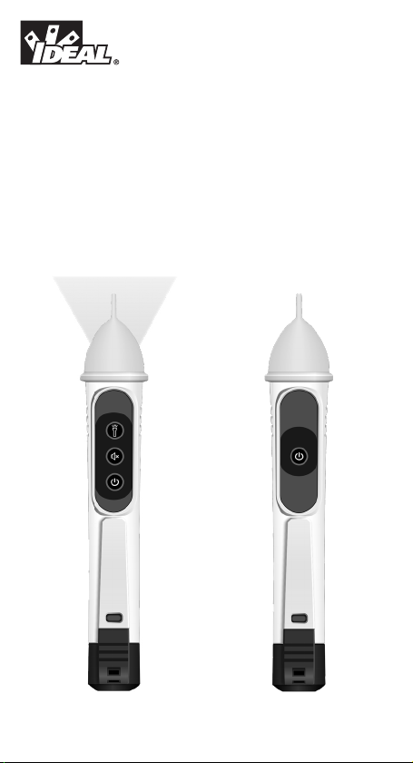
61-637 Single Range
24 to 600V AC NCVT with Flashlight
61-627 Single Range
50 to 600V AC NCVT
Operation and Safety Manual
Page 2

Notes
TestEquipmentDepot.com
Page 3

Table of Contents
Introduction ...................................................................... 4
Contacting IDEAL INDUSTRIES, INC ......................................... 4
Safety Information .............................................................. 5
Warnings ...................................................................................................5-6
Cautions ....................................................................................................... 6
Symbols ....................................................................................................... 7
Operation..................................................................... 8-14
Identification and description of operating controls and functions ............8-9
Operating Features ..................................................................................... 10
Tester Operation .........................................................................................11
Checking for The Presence of AC Voltage .................................................. 12
61-637 NCV Sensing Indications Table ......................................................13
61-627 NCV Sensing Indications Table ......................................................13
Functions Operation Table .......................................................................... 13
Functions Indication Table .........................................................................14
Electrical Specifications ............................................................................. 14
Environmental Specifications ................................................14
Mechanical Specifications ...................................................15
EMC / EMI .......................................................................15
FCC ............................................................................15
Safety ............................................................................15
Maintenance and Service ....................................................16
Disposal and Warranty ........................................................17
3
Page 4

Introduction
The IDEAL 61-637 and 61-627 Single Range Non-Contact Voltage Testers
automatically detect and indicate the presence of voltage within specified ranges.
The 61-637 detects voltage within a range of 24-600V AC and the 61-627 detects
voltage within a range of 50-600V AC. Both testers provide non-contact detection
of voltage through an antenna enclosed in plastic at the tip of the tester which
senses the presence of the electromagnetic field present around live conductors.
The 61-637 has a flash light that works independently of the testing function and is
activated by an independent On/Off button.
Arc Flash and Shock Hazard, Proper PPE Required. Follow all safety procedures,
wear proper PPE in accordance to NFPA 70E. Read and fully understand the
instruction manual prior to using this product. Failure to comply can result in
serious injury or death.
4
Page 5
Safety Information
possible death or serious injury if the hazard is realized.
Caution - Identifies conditions and actions that could result in tester dam-
age, equipment under test damage or data loss if the hazard is realized.
Warning - Identifies conditions and actions that could result in
WARNING
Arc Flash and Shock Hazard, Proper PPE Required. Follow all safety procedures,
wear proper PPE in accordance to NFPA 70E and follow the guidelines below and
the instructions in this manual when operating the tester. Failure to comply can
result in serious injury or death.
• Choking Hazard, Small Parts. Keep Away from Children Sharp Objects
Hazard, This is not a toy. It is not for use or play by children. Keep
Away from Children. Failure to do so can result in serious injury.
• Only experienced or technically competent consumers should use this
equipment. When in doubt, call an experienced electrician to make any and
all necessary repairs or installations. At all times, perform any necessary
work on a de-energized circuit that has had its circuit breaker turned off and
has been locked out.
• Use the Tester only as specified in this manual or protection provided by the
Tester can be compromised.
• Before using the Tester, visually inspect it to ensure the case or tip are not
cracked and the battery cap is securely in place. Do not use if the Tester
appears damaged.
• When using the tester, keep fingers behind the tactile barrier at the base of
the tester. (see #4 on page 9)
• This Tester is intended for use by qualified electricians and competent
consumers. Follow NFPA 70E Standards for Electrical Safety when using
this Tester.
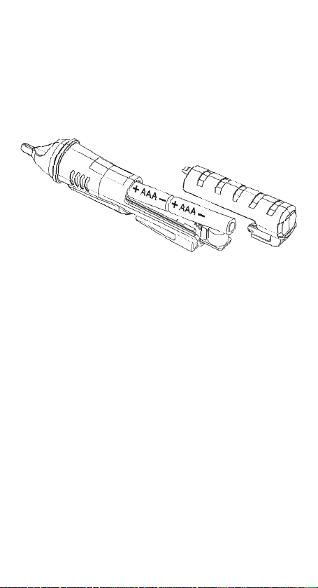
• Do not use without the batteries correctly in place and the slide on battery
cover secured.
• Do not use Tester if it operates incorrectly as protection may be
compromised. When in doubt, have the Tester serviced.
5
Page 6

WARNING
Arc Flash and Shock Hazard, Proper PPE Required. Follow all safety procedures,
wear proper PPE in accordance to NFPA 70E and follow the guidelines below and
the instructions in this manual when operating the tester. Failure to comply can
result in serious injury or death.
• Have the Tester serviced only by qualified service personnel.
• Do not use the Tester around explosive gas, dust, or vapor, or during electrical
storms, or in wet environments.
• Do not apply more than the rated voltage, as marked on the Tester. Observe
CAT Rating of Tester when in use.
• To avoid false readings that can lead to electrical shock and injury, replace the
batteries as soon as the low battery indication appears.
• Voltages exceeding 30VAC or 60VDC pose a shock hazard so use caution.
• Do not work alone so that assistance can be rendered in an emergency.
Use extreme caution when working around bare conductors or bus bars.
•
Contact with the conductor could result in electric shock.
• Adhere to local and national safety codes. Individual protective equipment
must be used to prevent shock and arc blast injury where hazardous live
conductors are exposed.
• Cancer and Reproductive Harm
CAUTION
Tester damage can occur if the following guidelines are not adhered to.
• Use the proper settings and voltage ratings for the measurement application.
• Clean the case and accessories with a damp cloth and mild detergents only.
Do not use abrasives or solvents. Make sure the tester is completely dry
before use.
• Not intended for insertion into electrical outlet slots.
• Do not apply excessive side or torsional loading to the sensing tip as
damage may occur.
6
Page 7
Symbols & Descriptions
SYMBOL DESCRIPTION
Arc Flash and Shock Hazard
Shock Hazard
Warning or Caution
Choking Hazard
AC (Alternating Current)
Earth Ground
CAT III
CAT IV
IEC Measurement Category III
CAT III has protection against transients in equipment in fixedequipment installations such as distribution panels feeders,
and short branch circuits. Also included are lighting systems in
larger buildings.
IEC Measurement Category IV
CAT IV has protection against transients from the primary
supply level such as a Meter or overhead or underground utility
service.
Voltage AC
V
Double Insulation
Do not dispose of this product as unsorted municipal waste.
It must be properly disposed of in accordance with local
regulations.
Conforms to applicable North American Safety Standards
Conforms to applicable Australian Safety Standards
Conforms to European Directives
NOTE: Tester must be used within the designated CAT Rating.
7
Page 8

Operation
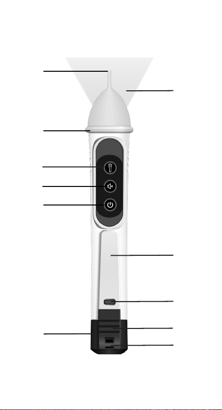
Identification and Description of Operating
Functions for the 61-637 Single Range 24
to 600V AC NCVT w/ Flashlight and 61-627
Single Range 50 to 600V AC NCVT:
1. Power On/Off button
2. Audible Notification On/Off button (61-637 Only)
3. Flashlight On/Off button (61-637 Only)
4. Tactile Barrier
5. Non-Contact Voltage Sensing Tip
6. Flashlight (61-637 Only)
7. Pocket Clip
8. Battery Cover Locking Point
9. Battery Cover Release Point
10. Lanyard Tie Off Point
11. Battery Cover
8
Page 9
5
6
4
3
2
1
7
8
11
9
10
9
Page 10

Operating Features
Audible Notification Disable (61-637 Only)
The tester can be operated with a visual only indication of voltage when working in
noise sensitive/noise restricted areas. With the tester On, press the Speaker button
for less than 1s. The tester will beep once to indicate the audible warning is muted
and only a visual indication will be provided. To restore the audible warning, press
the speaker button for less than 1s. The tester will beep twice to indicate the audible
warning is active and both a visual and audible indication will be provided. The
tester is set to Audible Notification On as the default setting.
Flashlight (61-637 Only)
An LED Flashlight in the tip operates independently of the tester functions and can
be used to illuminate the work area. Press the Flashlight Button to turn it On/Off.
The tester is set to Flashlight Off. The Flashlight will Auto Power Off after 5 minutes
of no voltage detection. Further voltage detection will reset the APO function to 5
minutes again.
Note: Use of the flashlight will decrease battery life.
Auto Power Off
After 10 minutes of inactivity (no button pressed and no signals detected), the
tester will emit one long beep (~0.5s) and then shut off. Note: if the flashlight is on,
it will be also shut off.
Low Battery Indication
If battery voltage is less than around 2.4V, the green led in the tip will flash 3 times
and the buzzer will send out one long beep, then turn off the device.
10
Page 11
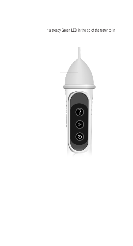
Tester Operation
Turning The Tester On
Press the Power On/Off button for less than 1s to turn the tester On. The tester
will beep twice, and will light a steady Green LED in the tip of the tester to indicate
Power On.
Steady Green LED in the tip
indicates power-on
Turning The Tester Off
Press the Power On/Off button for more than 1s to turn the tester Off. Listen for a
long steady beep (~.5s) and watch for LED in the tip to turn off. The tester is now
deactivated and is not operational.
11
Page 12
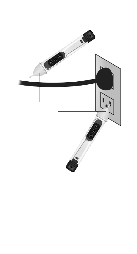
Checking for The Presence of AC Voltage
Prior to use, test on known live circuit to verify tester functionality. Place tip of the
tester near an AC voltage source and refer to the NCV Sensing Indications Table for
tester indication during operation.
Flashing Red LED in the tip and
intermittent beeping indicate
voltage is present. (See NCV
Sensing Indications table for
indications associated with each
range and mode setting)
While the NCV is a helpful function, it is ALWAYS RECOMMENDED that the
operator verify that any electrical conductor is completely deenergized and that
no voltage is present by measuring for voltage AND CONFIRMING THAT NO
VOLTAGE IS PRESENT and that all applicable PPE and lock out tag out procedures
be followed before attempting any work on ANY electrical distribution system.
Voltages with frequencies higher than 60Hz or electrostatic charges may also be
detected by the NCV sensing antenna. Due to the variability of designs across
device manufactures the 61-627 and 61-637 may not detect the presence of voltage
in Tamper Resistant Outlets.
12
Page 13

61-637 NCV Sensing Indications Table
NCV
Indications
Mode
18-25V 26-34V 35-45V 46-54V 55-600V
Ranges (V AC)
Red
Normal Mode
(24-600V AC)
Audible
Notification
Disabled
(24-600V AC)
Note: Indications above may be subject to variability caused by humidity, insulation
thickness, distance, and other factors.
Flashing
Light in Tip
and beeps
@ 2Hz
Red
Flashing
Light in Tip
@ 2Hz, No
beeps
Red
Flashing
Light in
Tip and
beeps
from 2Hz
to 4Hz
Red
Flashing
Light in
Tip from
2Hz to
4Hz, No
beeps
Red
Flashing
Light in Tip
and beeps
@ 4Hz
Red
Flashing
Light in Tip
@ 4Hz, No
beeps
Red
Flashing
Light in Tip
and beeps
from 4Hz
to 12 Hz
Red
Flashing
Light in Tip
from 4Hz
to 12Hz,
No beeps
Red Flashing
Light in Tip
and beeps
@ 12Hz
Red Flashing
Light in Tip
@ 12Hz, No
beeps
61-627 NCV Sensing Indications Table
NCV
Indications
Mode
Normal Mode
(50-600V AC)
Note: Indications above may be subject to variability caused by humidity, insulation
thickness, distance, and other factors.
Ranges (V AC)
50-600V AC
Red Flashing Light in Tip and beeps @ 12Hz
Functions Operation Table
Indication Response Default Function Operation
On Off Meter On GREEN LED Push Button
Audible
(61-637 Only)
Flashlight
(61-637 Only)
Beeps On Push Button
Flashlight On Off Push Button
13
Page 14

Functions Indication Table
Function Description
Power On Steady Greenlight in Tip,
Power Off No Light, Long Beep
Tester Auto Power Off Green Light Flashes, 1 Beep
Audible OFF
(61-637 Only)
Audible ON
(61-637 Only)
Flashlight Button
(61-637 Only)
2 Short Beeps
One Beep
Two Beeps
Flashlight On or Off
Electrical Specifications
Function Range
AC Voltage Sensing 61-637 24V AC to 600V AC
AC Voltage Sensing 61-627 50V AC to 600V AC
Frequency 50Hz or 60Hz AC
Environmental Specifications
Operating Temperature: 32ºF to 104ºF (0ºC to 40ºC) (<80%RH)
Operating Altitude:
Storage Temperature:
Intended for indoor use.
6500 ft (2000 m)
14ºF to 122ºF (-10ºC to 50ºC) (<80%RH)
14
Page 15

Mechanical Specifications
Dimensions: (L x W x H) 6.0 in. x 1.0 in. x 1.1 in.
Weight: 0.13 LBS (0.06 KG)
Power Source: (2) 1.5V AAA Batteries
Flashlight:
(61-637)
(154 mm x 26 mm x 29 mm)
>500LUX @ 4 in
EMC/EMI
CISPR 22 3rd Edition. Class B Limits.
EN 55032
CISPR 32
CISPR 11
FCC 15. 107 with reference to Section 15.109 (g).
ICES-003
EN 61326-2-2 Sec 6.4.2.101
USA (FCC)
47 CFR 15 subpart B. This product is considered an exempt device per clause 15.103.
Safety
Complies with the following:
IEC 61010-1, Edition 3 (2010-06) +AMD1 (2016-12)
ANSI/UL/IEC EN 61010-1, Edition 3 (2016-04-29)
CSA-C22.2 No. 61010-1-12 Edition 3 (2019-07-19)
IEC 60529
Overvoltage CAT IV 600V.
Any voltages exceeding the defined maximum voltage measurement categories
described above are outside the normal use of the equipment and protection cannot
be guaranteed.
Pollution Degree Class 2
15
Page 16
Maintenance and Service
Tester Inspection
Before using the Tester, visually inspect it to ensure the case or tip are not cracked
and the battery cover is securely locked in place. Do not use if the Tester appears
damaged.
Battery Inspection/Replacement
Maintenance and Storage
When not in use, turn the meter off. If the tester will not be used
for more than a month remove the batteries for storage. Clean the
case with a damp cloth and mild detergent. Do not use abrasives or
solvents. If the meter is exposed to water ensure the tester is
completely dry before use. Do not expose to chemicals or solvents.
Service and Replacement Parts
This unit has no user-serviceable parts.
16
Page 17

Disposal of Waste, Electrical & Electronic Equipment
In order to preserve, protect and improve the quality of the environment, protect
human health and utilize natural resources prudently and rationally, the user should
return unserviceable product to relevant facilities in accordance with statutory
regulations. The crossed-out wheeled bin indicates the product needs to be
disposed separately and not as municipal waste.
Do not dispose of this product as unsorted municipal waste. It must be properly
disposed of in accordance with local regulations.
Disposal of Used Batteries/Accumulators
The user is legally obliged to return used batteries and accumulators. Disposing
used batteries in household waste is prohibited! Batteries/accumulators containing
hazardous substances are marked with the crossed-out wheeled bin. The symbol
indicates that the product is forbidden to be disposed via domestic refuse. The
chemical symbols for the respective hazardous substances are Cd = Cadmium, Hg
= Mercury, Pb = Lead.
You can return used batteries/accumulators free of charge to any collecting point
your local authority, our stores, or where batteries/accumulators are sold.
Consequently, you must comply with your legal obligations and contribute to
environmental protection.
TWO YEAR LIMITED WARRANTY
This tester is warranted to the original purchaser against defects in material and
workmanship for a period of two (2) years from date of purchase. With proof of
purchase from an authorized IDEAL distributor, a defective tester will be repaired or
replaced with the same product or a functionally equivalent product, at the option of
IDEAL INDUSTRIES, INC. during the warranty period, subject to verification
of the defect or malfunction. Warranty does not cover consumables such as fuses,
batteries, and excludes defects caused by leakage from batteries, abuse,
mishandling, dropping, ordinary wear and tear, misuse, neglect, unauthorized
repair, improper use, alterations, accidents or any causes beyond IDEAL’s
reasonable control. Consequential or incidental damages are not recoverable under
this warranty. Some states do not allow the exclusion or limitation of incidental or
consequential damages, so the above limitation or exclusion may not apply to you.
This LIMITED WARRANTY gives you specific legal rights, which vary from state to
state. This warranty constitutes the sole and exclusive remedy of the purchaser and
the exclusive liability of IDEAL, and is in lieu of any and all other warranties, and
expressly disclaims all other warranties, implied, or statutory as to merchantability,
fitness for purpose sold, description, quality productiveness, or any other matter.
No agent, distributor or other supplier has the authority to modify or amend this
warranty or make other representations or warranties other than those contained in
this warranty without express written authorization from IDEAL. For warranty
service, call IDEAL customer service at 1-800-435-0705.
Made in China.
of
17
Page 18

Scan the barcode on the right to see the new IDEAL T&M Product Line
Page 19

IDEAL® Prueba y Medición
61-637 Rango Singular
24 a 600V CA NCVT con Linterna
61-627 Rango Singular
50 a 600V CA NCVT
Manual de Operación y Seguridad
Instrucciones en español adentro / Instructions en français à l’intérieur
Page 20

Notas
Page 21

Índice
Introducción ....................................................................22
Cómo contactar IDEAL INDUSTRIES, INC ..................................22
Información de Seguridad ....................................................23
Advertencias ..........................................................................................23-24
Precauciones ..............................................................................................24
Símbolos ....................................................................................................25
Operación ...................................................................26-32
Identificación y descripción de controles de operación y funciones ......26-27
Funciones de Operación .............................................................................28
Operación de Probador .............................................................................. 29
Comprobación de la Presencia de Voltaje de CA ........................................30
Tabla de Indicaciones de Detección de 61-637 NCV ..................................31
Tabla de Indicaciones de Detección de 61-627 NCV ..................................31
Tabla de Operaciones de Funciones ...........................................................31
Tabla de Indicación de Funciones ..............................................................32
Especificaciones Eléctricas .........................................................................32
Especificaciones Ambientales ...............................................32
Especificaciones Mecánicas .................................................33
EMC/EMI.........................................................................33
FCC ............................................................................33
Seguridad .......................................................................33
Mantenimiento y Servicio ....................................................34
21
Page 22

Introducción
Los Probadores de Voltaje Sin Contacto IDEAL 61-637 y 61-627 detectan e
indican automáticamente la presencia de voltaje dentro de rangos especificados.
El 61-637 detecta voltaje dentro de un rango de 24-600V CA y el 61-627 detecta
voltaje dentro de un rango de 50-600V CA. Ambos probadores proporcionan
detección sin contacto de voltaje a través de una antena encerrada en plástico en la
punta del probador que detecta la presencia del campo electromagnético presente
alrededor de los conductores en vivo. El 61-637 tiene una linterna que funciona
independientemente de la función de prueba y se activa mediante un botón de
encendido/apagado independiente.
Peligro de Arco Eléctrico y Descarga Eléctrica, se Requiere el EPP Adecuado. Siga
todos los procedimientos de seguridad, use el EPP adecuado de acuerdo con NFPA
70E. Lea y comprenda completamente el manual de instrucciones antes de usar
este producto. El incumplimiento puede resultar en lesiones graves o la muerte.
22
Page 23

Información de Seguridad
Advertencia - Identifica condiciones y acciones que podrían
provocar la muerte o lesiones graves si se toma el riesgo.
Precaución -Identifica condiciones y acciones que podrían resultar en daño
al probador, daño al equipo bajo prueba o pérdida de datos si se toma el riesgo.
ADVERTENCIA
Peligro de Arco Eléctrico y Descarga Eléctrica, se Requiere el EPP Adecuado. Siga
todos los procedimientos de seguridad, use el EPP adecuado de acuerdo con NFPA
70E y siga las pautas a continuación y las instrucciones de este manual cuando
opere el probador. El incumplimiento puede resultar en lesiones graves o la muerte.
• Peligro de Asfixia, Partes Pequeñas. Mantener Fuera del Alcance de
• los Niños. Peligro de Objetos Afilados, Esto no es un juguete. No
es para uso o juego de niños. Mantener Fuera del Alcance de los Niños. No
hacerlo puede resultar en lesiones graves.
• Solo los consumidores experimentados o técnicamente competentes deben
utilizar este equipo. En caso de duda, llame a un electricista experimentado
para que realice todas las reparaciones o instalaciones necesarias. En todo
momento, realice cualquier trabajo necesario en un circuito desenergizado
al que se le haya apagado el cortacircuitos y se haya bloqueado.
• Utilice el Probador solo como se especifica en este manual o la protección
proporcionada por el Probador puede verse comprometida.
• Antes de usar o conectar el Probador, revíselo visualmente para asegurarse
de que las carcasas no estén agrietadas y que la carcasa posterior esté bien
colocada. No use el Probador sí parece dañado.
• Cuando utilice el probador, mantenga los dedos detrás de la barrera táctil en
la base del probador. (ver #4 en la página 27)
• Este Probador está diseñado para ser utilizado por electricistas calificados
y consumidores competentes. Siga las Normas NFPA 70E para Seguridad
Eléctrica en el lugar de trabajo cuando utilice este Probador.
• No lo utilice sin las baterías correctamente colocadas y la tapa deslizante de
las baterías asegurada.
• No utilice el Probador si funciona incorrectamente, ya que la protección
puede verse comprometida. En caso de duda, lleve el Probador a que le
hagan servicio.
23
Page 24

ADVERTENCIA
Peligro de Arco Eléctrico y Descarga Eléctrica, se Requiere el EPP Adecuado. Siga
todos los procedimientos de seguridad, use el EPP adecuado de acuerdo con NFPA
70E y siga las pautas a continuación y las instrucciones de este manual cuando
opere el probador. El incumplimiento puede resultar en lesiones graves o la muerte.
• Únicamente permita que el servicio del Probador lo lleve a cabo personal de
servicio calificado.
• No utilice el Probador cerca de gases, polvo o vapores explosivos, o durante
tormentas eléctricas o en entornos húmedos.
• No aplique más de el voltaje nominal, como se marca en el Probador. Observe
la calificación CAT del probador cuando esté en uso.
• Para evitar lecturas falsas que pueden provocar descargas eléctricas y
• Los voltajes que excedan los 30VCA o 60VCD representan un peligro de
• No trabaje solo para que se pueda prestar asistencia en caso de emergencia.
• Tenga mucho cuidado al trabajar cerca de conductores pelados o barras
• Cumpla con los códigos de seguridad locales y nacionales. Se debe utilizar
• Cáncer y Daño Reproductivo
reemplace las baterías tan pronto como aparezca el indicador de
lesiones,
baterías bajas.
descarga eléctrica, así que tenga cuidado.
colectoras. El contacto con el conductor podría provocar una descarga
eléctrica.
equipo de protección individual para evitar descargas eléctricas y lesiones
por explosión de arco cuando se exponen conductores activos peligrosos.
PRECAUCIÓN
Pueden producirse daños en el comprobador si no se siguen las siguientes pautas.
• Utilice los ajustes y las clasificaciones de voltaje adecuados para la
aplicación de medición.
• Únicamente limpie la carcasa y los accesorios con un paño húmedo y
detergentes suaves. No utilice abrasivos o solventes. Asegúrese de que el
probador esté totalmente seco antes de usar.
• No está diseñado para su inserción en las ranuras de tomacorrientes
eléctricos.
• No aplique una carga lateral o de torsión excesiva a la punta sensora, ya que
pueden ocurrir daños.
24
Page 25

Símbolos y Descripciones
SÍMBOLO DESCRIPCIÓN
Peligro de Arco Eléctrico y Descarga Eléctrica
Peligro de Descarga Eléctrica
Advertencia o Precaución
Peligro de Asfixia
CA (Corriente Alterna)
Tierra
CAT III
CAT IV
Categoría de Medición IEC III
CAT III tiene protección contra transitorios en equipos en
instalaciones de equipos fijos como paneles de distribución,
alimentadores y circuitos derivados cortos. También se incluyen
sistemas de iluminación en edificios más grandes.
Categoría de Medición IEC IV
CAT IV tiene protección contra transitorios del nivel de
suministro primario, como un Contador o un servicio público
subterráneo o aéreo.
Voltaje CA
V
Aislamiento Doble
No elimine este producto como residuo municipal sin clasificar.
Debe desecharse adecuadamente de acuerdo con las regulaciones locales.
Cumple con los Estándares de Seguridad Norteamericanos
aplicables
Cumple con los Estándares de Seguridad Australianos
aplicables
Cumple con las Directivas Europeas
Nota: El probador debe utilizarse dentro de la clasificación CAT designada.
25
Page 26

Operación
Identificación y Descripción de las Funciones
de Operación para el 61-637 Rango Singular 24
a 600V CA NCVT con linterna y 61-627 Rango
Singular 50 a 600V CA NCVT:
1. Botón de Encendido/Apagado
2. Botón de Encendido/Apagado de Notificación Audible (Sólo 61-637)
3. Botón de Encendido/Apagado de la Linterna (Sólo 61-637)
4. Barrera Táctil
5. Punta de Detección de Voltaje Sin Contacto
6. Linterna (Sólo 61-637)
7. Clip de Bolsillo 3
8. Punto de Bloqueo de la Tapa de la Batería
9. Punto de Liberación de la Tapa de la Batería
10. Punto de Amarre del Cordón
11. Tapa de la Batería
26
Page 27

5
6
4
3
2
1
7
8
11
9
10
27
Page 28

Funciones de Operación
Deshabilitar Notificación Audible (Sólo 61-637)
El probador se puede utilizar con una indicación de voltaje sólo visual cuando
se trabaja en áreas sensibles al ruido/restringidos por ruido. Con el probador
Encendido, presione el botón Altavoz por menos de 1s. El probador pitará una vez
para indicar que la notificación audible está silenciada y sólo se proporcionará
una indicación visual. Para restaurar la notificación audible, pulse el botón
del altavoz por menos de 1s. El probador pitará dos veces para indicar que la
notificación audible está activa y se proporcionará una indicación visual y audible.
El probador está configurado a Notificación Audible Activada como configuración
predeterminada.
Linterna (Sólo 61-637 )
Una linterna LED en la punta funciona independientemente de las funciones
del probador y se puede utilizar para iluminar el área de trabajo. Pulse el Botón
Linterna para Encenderla/Apagarla. El probador está configurado a Linterna
Apagada. La Linterna se Apagará Automáticamente después de 5 minutos sin
detección de voltaje. La detección de voltaje adicional restablecerá la función APO
a 5 minutos de nuevo.
Nota: El uso de la linterna disminuirá la duración de la batería.
Apagado Automático
Después de 10 minutos de inactividad (sin presionar ningún botón y sin detectar
señales), el probador emitirá un pitido largo (0.5s) y luego se apagará. Nota: si la
linterna está encendida, también se apagará.
Indicador de Baterías Bajas
Si el voltaje de la batería es inferior a alrededor de 2.4V, el led verde en la punta
parpadeará 3 veces y el zumbador enviará un pitido largo, luego apagará el
dispositivo.
28
Page 29

Operación de Probador
Encender el Probador
Presione el Botón de Encendido/Apagado por menos de 1s para encender el
probador. El probador pitará dos veces, y encenderá un LED Verde constante en la
punta del probador para indicar que está Encendido.
El LED Verde fijo en la
punta indica encendido
Apagar el Probador
Presione el Botón de Encendido/Apagado por menos de 1s para apagar el
probador. Escuche por un pitido largo y constante (~.5s) y observe si el LED en la
punta se apaga. El probador ahora está desactivado y no está operativo.
29
Page 30

Comprobar la Presencia de Voltaje de CA
Antes de usar, pruebe en el circuito vivo conocido para verificar la funcionalidad
del probador. Coloque la punta del probador cerca de una fuente de voltaje de CA y
consulte la tabla de indicaciones de detección NCV para obtener la indicación del
probador durante el funcionamiento.
El LED Rojo Parpadeante en la
punta y el pitido intermitente
indican que hay voltaje presente.
(Consulte la tabla Indicaciones
de detección NCV para obtener
indicaciones asociadas a cada
ajuste de rango y modo)
Si bien el NCV es una función útil, SIEMPRE SE RECOMIENDA que el operador
verifique que cualquier conductor eléctrico esté completamente desenergizado y
que no haya voltaje presente midiendo el voltaje Y CONFIRMANDO QUE NO HAY
VOLTAJE PRESENTE y que todos los EPP y los procedimientos de bloqueo y de
etiquetado aplicables se sigan antes de intentar cualquier trabajo en CUALQUIER
sistema de distribución eléctrica. La antena de detección NCV también puede
detectar voltajes con frecuencias superiores a 60 Hz o cargas electrostáticas.
Debido a la variabilidad de los diseños entre los fabricantes de dispositivos,
es posible que el 61-627 y 61-637 no detecte la presencia de voltaje en los
Tomacorrientes a Prueba de Manipulaciones.
30
Page 31

Tabla de Indicaciones de Detección de 61-637 NCV
NCV
Indicaciones
Modo
18-25V 26-34V 35-45V 46-54V 55-600V
Rangos (V CA)
Modo Normal
(24-600V CA)
Notificación
Audible
Deshabilita da
(24-600V CA)
Luz Roja
Parpadeante
en la Punta
Luz Roja
Parpadeante
en la Punta
@ 2Hz, Sin
y pita
@ 2Hz
Pitidos
Luz Roja
Parpadeante
en la Punta
y pita de
2Hz a 4Hz
Luz Roja
Parpadeante
en la Punta
de 2Hz a
4Hz, Sin
Pitidos
Luz Roja
Parpadeante
en la Punta y
pita @ 4Hz
Luz Roja
Parpadeante
en la Punta
@ 4Hz, Sin
Pitidos
Luz Roja
Parpadeante
en la Punta
y pita de
4Hz a 12Hz
Luz Roja
Parpadeante
en la Punta
de 4Hz a
12Hz, Sin
Pitidos
Luz Roja
Parpadeante
en la Punta y
pita @ 12Hz
Luz Roja
Parpadeante
en la Punta
@ 12Hz, Sin
Pitidos
Nota: Las indicaciones anteriores pueden estar sujetas a la variabilidad causada por
la humedad, el grosor del aislamiento, la distancia y otros factores.
Tabla de Indicaciones de Detección de 61-627 NCV
Indicaciones
NCV
Modo
Modo Normal
(50-600V CA)
Luz Roja Parpadeante en la Punta y pita @ 12Hz
Nota: Las indicaciones anteriores pueden estar sujetas a la variabilidad causada por
la humedad, el grosor del aislamiento, la distancia y otros factores.
Rangos (V CA)
50-600V CA
Tabla de Operaciones de Funciones
Indicación Respuesta
Encendido/Apagado Probador
Audible (Sólo 61-637) Pita Encendido Botón
Linterna (Sólo 61-637) Linterna
Encendido
Encendida
Función
Predeterminada
LED VERDE Botón
Apagado Botón
Operación
31
Page 32

Tabla de Indicación de Funciones
Función Descripción
Encendido Luz verde constante en Punta, 2 Pitidos Cortos
Apagado Sin Luz, Pitido Largo
Apagado Automático del
Probador
Audible APAGADO (Sólo
61-637)
Audible ENCENDIDO
(Sólo 61-637)
Botón de Linterna (Sólo
61-637)
Luz Verde Parpadea, 1 Pitido
Un Pitido
Dos Pitidos
Linterna Encendida o Apagada
Especificaciones Eléctricas
Función Rango
Detección de Voltaje CA 61-637 24V CA a 600V CA
Detección de Voltaje CA 61-627 50V CA a 600V CA
Frecuencia 50Hz o 60Hz CA
Especificaciones Ambientales
Temperatura Operativa: 32ºF a 104ºF (0ºC a 40ºC) (<80%RH)
Altitud Operativa:
Temperatura de Almacenamiento:
Destinado para uso en interiores.
6500 pies (2000 m)
14ºF a 122ºF (-10ºC a 50ºC) (<80%RH)
32
Page 33

Especificaciones Mecánicas
Dimensiones: (L x An x Al) 6.0 pulg. x 1.0 pulg. x 1.1 pulg. (154
Peso: 0.13 LBS (0.06 KG)
Fuente de Alimentación: (2) Baterías AAA de 1.5V
Linterna (61-637): >500LUX @ 4 in
mm x 26 mm x 29 mm)
EMC/EMI
CISPR 22 3a Edición. Límites de Clase B.
EN 55032
CISPR 32
CISPR 11
FCC 15. 107 con referencia al artículo 15.109 (g).
ICES-003
EN 61326-2-2 Sec 6.4.2.101
EE. UU. (FCC)
47 CFR 15 subparte B. Este producto se considera un dispositivo exento según la
cláusula 15.103.
Seguridad
Cumple con los siguientes:
IEC 61010-1, Edición 3 (2010-06) +AMD1 (2016-12)
ANSI/UL/IEC EN 61010-1, Edición 3 (2016-04-29)
No CSA-C22.2. 61010-1-12 Edición 3 (2019-07-19)
IEC 60529
Sobrevoltaje CAT IV 600V.
Cualquier voltaje que supere las categorías de medida de voltaje máximas definidas
descritas anteriormente está fuera del uso normal del equipo y no se puede garantizar la
protección.
Grado de Contaminación Clase 2
33
Page 34

Mantenimineto y Servicio
Inspección del Probador
Antes de usar el Probador, revíselo visualmente para asegurarse de que la carcasa
o la punta no estén agrietadas y que la tapa de la batería esté bien colocada en su
lugar. No use el Probador sí parece dañado.
Inspección/Reemplazo de las Baterías
Mantenimiento y Almacenamiento
Cuando no esté en uso, apague el medidor. Si el probador no se utilizará por más
de un mes, retire las pilas para su almacenamiento. Limpie la carcasa con un paño
húmedo y detergentes suaves. No utilice abrasivos o solventes. Si el medidor está
expuesto al agua, asegúrese de que el probador esté completamente seco antes de
usarlo. No exponer a productos químicos o solventes.
Servicio y Repuestos
Esta unidad no tiene piezas que el usuario pueda reparar.
34
Page 35

Eliminación de Residuos, Equipos Eléctricos y Electrónicos
Para preservar, proteger y mejorar la calidad del medio ambiente, proteger la salud
humana y utilizar los recursos naturales de manera prudente y racional, el usuario
debe devolver el producto inservible a las instalaciones correspondientes de
acuerdo con las regulaciones legales. El contenedor con ruedas tachado indica que
el producto debe desecharse por separado y no como basura municipal.
No elimine este producto como residuo municipal sin clasificar. Debe desecharse
adecuadamente de acuerdo con las regulaciones locales.
Eliminación de Baterías/Acumuladores Usados
El usuario está legalmente obligado a devolver las baterías y acumuladores usados.
¡Está prohibido eliminar las baterías usadas en los residuos domésticos! Las
baterías/acumuladores que contienen sustancias peligrosas están marcados con el
contenedor con ruedas tachado. El símbolo indica que está prohibido eliminar el
producto a través de la basura doméstica. Los símbolos químicos de las sustancias
peligrosas respectivas son Cd = Cadmio, Hg = Mercurio, Pb = Plomo.
Puede devolver las baterías/acumuladores usados de forma gratuita a cualquier
punto de colección de su autoridad local, nuestras tiendas o donde se vendan
baterías/ acumuladores. En consecuencia, debe cumplir con sus obligaciones
legales y contribuir a la protección del medio ambiente.
GARANTÍA LIMITADA DE DOS AÑOS
Este medidor está garantizado para el comprador original contra defectos de
materiales y mano de obra por un período de dos (2) años a partir de la fecha de
compra. Con un comprobante de compra de un distribuidor IDEAL autorizado, un
medidor defectuoso será reparado o reemplazado con el mismo producto
o un producto funcionalmente equivalente, a opción de IDEAL INDUSTRIES,
INC. durante el período de garantía, sujeto a la verificación del defecto o mal
funcionamiento. La garantía no cubre los consumibles como fusibles, baterías y
excluye los defectos causados por fugas de baterías, abuso, mal manejo, caída,
desgaste normal, mal uso, negligencia, reparación no autorizada, uso indebido,
alteraciones, accidentes o cualquier otra causa que exceda los límites del control
razonable de IDEAL. Los daños consecuentes o incidentales no son recuperables
bajo esta garantía. Algunos estados no permiten la exclusión o limitación de
daños incidentales o consecuentes, por lo que la limitación o exclusión anterior
puede no aplicarse en su caso. Esta GARANTÍA LIMITADA le otorga derechos
legales específicos, que varían de estado a estado. Esta garantía constituye el
único y exclusivo recurso del comprador y la responsabilidad exclusiva de IDEAL,
y sustituye a todas y cada una de las otras garantías, y renuncia expresamente a
todas las demás garantías, implícitas o reglamentarias en cuanto a comerciabilidad,
idoneidad para el propósito vendido, descripción, productividad de calidad o
cualquier otro asunto. Ningún agente, distribuidor u otro proveedor tiene la
autoridad para modificar o enmendar esta garantía o hacer otras declaraciones o
garantías distintas de las contenidas en esta garantía sin la autorización expresa
por escrito de IDEAL. Para obtener servicio de garantía, llame al servicio al cliente
de IDEAL al 1-800-435-0705.
Hecho en China.
35
Page 36

Escanee el código de barras a la derecha para ver la nueva Línea de Productos IDEAL T&M
Page 37

Essai et Mesure IDEAL
®
61-637 Gamme Unique
24 à 600V CA NCVT avec Lampe de
Poche
61-627 Plage Unique
50 à 600V CA NCVT
Manuel d’utilisation et de Sécurité
Instrucciones en español adentro / Instructions en français à l’intérieur
Page 38

Notes
Page 39

Table des Matières
Introduction. ....................................................................40
Entrer en contact avec IDEAL INDUSTRIES, INC. .........................40
Information sur la sécurité. ..................................................41
Avertissements, .....................................................................................41-42
Précautions ................................................................................................ 42
Symboles. .................................................................................................. 43
Fonctionnement ............................................................44-50
Identification et description des commandes de fonctionnement
et Fonctions .....................................................................................44-45
Fonctionnalités de fonctionnement. ............................................................46
Fonctionnement du testeur. ........................................................................47
Vérification de la présence de tension alternative. ...................................... 48
61-637 Tableau des indications de détection NCV. ..................................... 49
61-627 Tableau des indications de détection NCV. ..................................... 49
Tableau d’utilisation des fonctions. ............................................................49
Tableau d’indication des fonctions. ............................................................50
Spécifications électriques. ..........................................................................50
Caractéristiques environnementales. ......................................50
Caractéristiques mécaniques. ...............................................51
EMC/EMI.........................................................................51
FCC. ............................................................................51
Sécurité .........................................................................51
Entretien et dépannage. ......................................................52
39
Page 40

Introduction
Les testeurs de tension sans contact à plage unique IDEAL 61-637 et 61-627
détectent et indiquent automatiquement la présence de tension dans les plages
spécifiées. Le 61-637 détecte la tension dans une plage de 24 à 600 V CA et le
61-627 détecte la tension dans une plage de 50 à 600 V CA. Les deux testeurs
fournissent une détection sans contact de la tension grâce à une antenne enfermée
dans du plastique à l’extrémité du testeur qui détecte la présence du champ
électromagnétique présent autour des conducteurs sous tension. Le 61-637 a une
lampe torche qui fonctionne indépendamment de la fonction de test et est activée
par un bouton marche/arrêt indépendant.
Risque d’arc électrique et d’électrocution, matériel de protection individuelle
adéquat requis. Observez toutes les mesures de sécurité, portez le matériel de
protection individuelle conforme à la norme NFPA 70E. Lisez et assurez-vous
d’avoir bien compris la notice d’utilisation avant d’utiliser ce produit. Ne pas se
conformer peut entraîner des risques de graves lésions ou la mort.
40
Page 41

Consignes de sécurité
Avertissement - identifie des conditions et des actions qui
pourraient entraîner la mort ou des lésions graves si le danger se manifestait.
Précaution - identifie les états et les actions qui pourraient entraîner
l’endommagement du multimètre ou du matériel testé ou une perte de données si le
danger se manifestait.
AVERTISSEMENT
Risque d’arc électrique et d’électrocution, matériel de protection individuelle
adéquat requis. Observez toutes les mesures de sûreté, portez le matériel de
protection individuelle adéquat conforme à la norme NFPA 70E et suivez les
directives ci-dessous et les instructions en ce manuel en actionnant le multimètre.
Ne pas se conformer peut entraîner des risques de graves lésions ou la mort.
• Risque d’étouffement, petites pièces. Conservez hors de portée des
enfants. Risque afférent aux d’objets pointus. Ceci n’est pas un jouet. Il
n’est pas conçu pour une utilisation par des enfants ou comme un jouet.
Conservez hors de portée des enfants. À défaut, cela pourra entraîner des
lésions graves ou la mort.
• Seuls les consommateurs expérimentés ou techniquement compétents
doivent utiliser cet équipement. Dans le doute, appelez un électricien
expérimenté pour faire toutes les réparations ou installations nécessaires.
À tout moment, effectuez n’importe quel travail nécessaire sur un circuit
désactivé qui a eu son disjoncteur arrêté et a été verrouillé.
• Utilisez le testeur uniquement comme spécifié dans ce manuel ou la
protection fournie par le testeur peut être compromise.
• Avant d’utiliser le testeur, inspectez-le visuellement pour vous assurer que le
boîtier ou la pointe ne sont pas fissurés et que le couvercle de la batterie est
bien en place. Ne pas utiliser si le testeur semble endommagé.
• Lorsque vous utilisez le testeur, gardez les doigts derrière la barrière tactile à
la base du testeur. (voir # 4 à la page 45)
• Ce testeur est destiné à être utilisé par des électriciens qualifiés et des
consommateurs compétents. Suivez les normes NFPA 70E pour la sécurité
électrique lors de l’utilisation de ce testeur.
• N’utilisez que si les piles sont correctement montées et avec le couvercle de
• piles fermé et assujetti.
• N’utilisez pas le testeur s’il ne fonctionne pas normalement, car la protection
peut être compromise. En cas de doute, faites réparer le testeur.
41
Page 42

ATTENTION
Risque d’arc électrique et d’électrocution, matériel de protection individuelle
adéquat requis. Observez toutes les mesures de sûreté, portez le matériel de
protection individuelle adéquat conforme à la norme NFPA 70E et suivez les
directives ci-dessous et les instructions en ce manuel en actionnant le testeur Ne
pas se conformer peut entraîner des risques de graves lésions ou la mort.
• Le testeur ne doit être entretenu que par un personnel de service qualifié.
• N’utilisez pas le testeur en présence de gaz, poussière ou vapeur explosifs,
pendant des orages ou dans des environnements humides.
• N’appliquez pas plus que la tension nominale indiquée sur le testeur.
Observez la classification CAT du testeur lors de son utilisation.
Pour éviter les fausses lectures qui peuvent provoquer électrocution et
•
blessures, remplacent les piles dès que l’indicateur de batterie déchargée ()
• s’affichera.
• Les tensions de plus de 30 V CA ou 60 V CC posent un danger d’électrocution,
faites donc preuve
• Ne travaillez pas seul de sorte qu’on puisse vous porter assistance en cas
d’urgence.
• Faites très attention en travaillant aux alentours de conducteurs dénudés ou
de barres omnibus. Tout contact avec le conducteur pourrait entraîner une
électrocution.
• Observez les codes locaux et nationaux de sécurité. Le matériel de protection
individuelle doit être utilisé pour empêcher toute électrocution ou lésion par
arc électrique en présence de conducteurs sous tension dénudés.
• Cancer et dangers pour la reproduction
ATTENTION
Le testeur peut être endommagé si les directives suivantes ne sont pas respectées.
• Utilisez les bornes, la fonction, et la plage adéquates pour l’application de
mesure.
• Nettoyez le boîtier et les accessoires avec un chiffon humide et des
détergents doux seulement. N’utilisez pas de produits abrasifs ou de
dissolvants. Assurez-vous que le testeur est complètement sec avant de
l’utiliser.
• Non destiné à être inséré dans les fentes de prise électrique.
• N’appliquez pas de charge latérale ou de torsion excessive sur la pointe de
détection car cela pourrait l’endommager.
42
Page 43

Symboles et descriptions
SIGNIFICATION DESCRIPTION
Risque d’arc électrique et d’électrocution,
Décharge électrique
Avertissement ou mise en garde
Risque d’étouffement
CA (courant alternatif)
Terre au sol
CAT III
CAT IV
Catégorie de mesure CEI III
CAT III offre une protection contre les transitoires dans les
équipements des installations fixes telles que les départs de
panneaux de distribution et les circuits de dérivation courts.
Sont également inclus les systèmes d’éclairage dans les
grands bâtiments.
Catégorie de mesure CEI IV
CAT IV a une protection contre les transitoires du niveau
d’alimentation primaire comme un multimètre ou un service
public aérien ou souterrain.
Tension CA
V
Isolation à double paroi
N’évacuez pas ce produit comme un déchet municipal non
trié. Il doit être correctement évacué en observant les règlements locaux.
Conforme aux normes de sécurité nord-américaine
applicables
Conforme aux normes de sécurité australienne applicables
Conforme aux directives européennes
REMARQUE : Le testeur doit être utilisé dans le cadre de la classification CAT
désignée.
43
Page 44

Fonctionnement
Identification et description des fonctions de
fonctionnement du 61-637 à plage unique 24 à
600 V CA NCVT avec lampe de poche et 61-627
Plage unique 50 à 600 V CA NCVT :
1. Bouton marche / arrêt
2. Bouton d’activation / désactivation de la notification sonore
(61-637 uniquement)
3. Bouton marche / arrêt de la lampe torche (61-637 uniquement)
4. Barrière tactile
5. Pointe de détection de tension sans contact
6. Lampe torche (61-637 seulement)
7. Clip de poche
8. Point de verrouillage du couvercle de la batterie
9. Point de dégagement du couvercle de la batterie
10. Point d’attache de la lanière
11. Couvercle de la batterie
44
Page 45

5
6
4
3
2
1
7
8
11
9
10
45
Page 46

Fonctionnalités de fonctionnement
Désactivation de la notification sonore (61-637 uniquement)
Le testeur peut être utilisé avec une indication visuelle uniquement de la tension
lorsque vous travaillez dans des zones sensibles au bruit / à bruit limité. Avec le
testeur allumé, appuyez sur le bouton Haut-parleur pendant moins de 1 s. Le testeur
émettra un bip pour indiquer que l’avertissement sonore est désactivé et seule une
indication visuelle sera fournie. Pour rétablir l’avertissement sonore, appuyez sur
le bouton du haut-parleur pendant moins de 1 s. Le testeur émettra deux bips pour
indiquer que l’avertissement sonore est actif et une indication visuelle et sonore
sera fournie. Le testeur est réglé sur Notification sonore activée comme paramètre
par défaut.
Lampe torche (61-637 uniquement)
Une lampe toche D.E.L. dans la pointe fonctionne indépendamment des fonctions
du testeur et peut être utilisée pour éclairer la zone de travail. Appuyez sur le bouton
de la lampe torche pour l’allumer / l’éteindre. Le testeur est réglé sur lampe torche
Off. La lampe torche s’éteindra automatiquement après 5 minutes sans détection
de tension. Une détection de tension supplémentaire réinitialisera la fonction APO
à 5 minutes.
Remarque : L’utilisation de la lampe torche réduira la durée de vie de la batterie.
Arrêt autoomatique
Après 10 minutes d’inactivité (aucun bouton enfoncé et aucun signal détecté), le
testeur émettra un long bip (~ 0,5 s) puis s’éteindra. Remarque : si la lampe torche
est allumée, elle sera également éteinte.
Indication de batterie faible
Si la tension de la batterie est inférieure à environ 2,4 V, le voyant vert de la pointe
clignotera 3 fois et l’avertisseur enverra un long bip, puis éteindra l’appareil.
46
Page 47

Fonctionnement du testeur
Allumer le testeur
Appuyez sur le bouton Marche / Arrêt pendant moins d’une seconde pour mettre le
testeur sous tension. Le testeur émettra deux bips et allumera une D.E.L. verte fixe
à l’extrémité du testeur pour indiquer la mise sous tension.
La D.E.L. verte fixe dans la
pointe indique la mise sous
tension
Éteindre le testeur
Appuyez sur le bouton Marche / Arrêt pendant plus d’une seconde pour éteindre
le testeur. Appuyez sur le bouton Marche / Arrêt pendant plus d’une seconde pour
éteindre le testeur.... Le testeur est maintenant désactivé et n’est pas opérationnel.
47
Page 48

Vérification de la présence de tension alternative.
Avant utilisation, effectuez un test sur un circuit sous tension connu pour vérifier
la fonctionnalité du testeur. Placez la pointe du testeur à proximité d’une source de
tension alternative et reportez-vous au tableau des indications de détection NCV
pour les indications du testeur pendant le fonctionnement.
Une D.E.L. rouge clignotante dans
la pointe et un bip intermittent
indiquent que la tension est
présente. (Voir le tableau des
indications de détection NCV pour
les indications associées à chaque
réglage de plage et de mode)
Bien que le NCV soit une fonction utile, il est TOUJOURS RECOMMANDÉ que
l’opérateur vérifie que tout conducteur électrique est complètement hors tension
et qu’aucune tension n’est présente en mesurant la tension ET EN CONFIRMANT
QU’AUCUNE TENSION N’EST PRÉSENTE et que toutes les procédures d’étiquetage
applicables en matière d’EPI et de verrouillage sont suivies avant de tenter tout
travail sur TOUT système de distribution électrique. Les tensions dont la fréquence
est supérieure à 60 Hz ou les charges électrostatiques peuvent également
être détectées par l’antenne de détection NCV. En raison de la variabilité des
conceptions entre les fabricants de dispositifs, les 61-627 et 61-637 peuvent ne
pas détecter la présence de tension dans les prises inviolables.
48
Page 49

61-637 Tableau des indications de détection NCV.
NCV
Indications
Mode
18-25V 26-34V 35-45V 46-54V 55-600V
Plages (V AC)
la pointe
et bip
@ 2Hz
de bip
Clignotant
rouge dans
la pointe
et émet un
bip de 2
Hz à 4 Hz
Clignotant
rouge dans
la pointe
de 2 Hz à
4 Hz, pas
de bips
Clignotant
rouge dans
la pointe
Clignotant
rouge dans
la pointe à
4 Hz, pas
Clignotant
Normal Mode
(24-600V AC)
Notification
sonore
désactivée
(24-600V AC)
Remarque : Les indications ci-dessus peuvent être sujettes à une variabilité causée
par l’humidité, l’épaisseur de l’isolant, la distance et d’autres facteurs.
rouge dans
Clignotant
rouge dans
la pointe à
2 Hz, pas
et bip
@ 4Hz
de bip
Clignotant
rouge dans
la pointe
et émet un
bip de 4 Hz
à 12 Hz
Feu
clignotant
rouge en
pointe de
4 Hz à 12
Hz,
Pas de bip
Clignotant
rouge dans
la pointe
et bip
@ 12Hz
Clignotant
rouge dans
la pointe
à 12 Hz,
pas de
bip
61-627 Tableau des indications de détection NCV.
NCV
Indications
Mode
Normal Mode
(50-600V AC)
Remarque : Les indications ci-dessus peuvent être sujettes à une variabilité causée
par l’humidité, l’épaisseur de l’isolant, la distance et d’autres facteurs.
Clignotant rouge dans la pointe et bip @ 12 Hz
Plages (V AC)
50-600V AC
Tableau d’utilisation des fonctions
Indication Réponse Fonction implicité Fonctionnement
On Off Multimètre
Audible
(61-637 uniquement)
Lampe de torche
(61-637 uniquement)
activé
Bip Marche Bouton-poussoir
Lampe torche
activé
GREEN LED Bouton-poussoir
Arrêt Bouton-poussoir
49
Page 50

Tableau d’indication des fonctions.
Function Description
Activer l’alimentation Feu vert fixe dans la pointe, 2 bips courts
Arrêter l’alimentation Pas de lumière, bip long
Arrêt automatique du
testeur
Audible OFF (61-637
uniquement)
Audible ON (61-637
uniquement)
Bouton de lampe torche
(61-637 uniquement)
Lumière verte clignote, 1 bip
Un bip
Deux bips
Lampe torche allumée ou éteinte
Spécifications électriques
Fonctions Plage
Détection de tension alternative 61-637 24V AC à 600V AC
Détection de tension alternative 61-627 50V AC à 600V AC
Fréquence 50Hz ou 60Hz AC
Environmental Specifications
Température de fonctionnement
Altitude de fonctionnement :
Température de stockage :
Destiné à une utilisation en intérieur.
32ºF à 104ºF (0ºC à 40ºC) (<80%RH)
6500 pi (2000 m)
14ºF à 122ºF (-10ºC à 50ºC) (<80%RH)
50
Page 51

Caractéristiques mécaniques.
Dimensions : (L x P x H)
Poids : (154 mm x 26 mm x 29 mm)
Sources d’énergie : 0.13 LB (0,06 KG)
Lampe torche : (2) 1.5 V AAA Piles
(61-637) >500 LUX @ 4 in
6.0 po x 1,0 po x 1,1 po
EMC/EMI
CISPR 22 3 rd Edition. Class B Limits.
EN 55 032
CISPR 32
CISPR 11
FCC 15. 107 en référence à la section 15 109 (g).
ICES-003
EN 61326-2-2 Sec 6.4.2.101
USA (FCC)
47 CFR 15 sous-partie B. Ce produit est considéré comme un appareil exempté
selon la clause 15 103.
Sécurité
Conforme à ce qui suit :
IEC 61010-1, Edition 3 (2010-06) +AMD1 (2016-12)
ANSI/UL/IEC EN 61010-1, Edition 3 (2016-04-29)
CSA-C22.2 No. 61010-1-12 Edition 3 (2019-07-19)
IEC 60529
Surtension CAT IV 600 V.
Toutes les tensions dépassant les catégories de mesure de tension maximale
définies décrites ci-dessus sont en dehors de l’utilisation normale de l’équipement
et la protection ne peut être garantie.
Degré de pollution Classe 2
51
Page 52

Entretien et dépannage
Inspection du testeur
Avant d’utiliser le testeur, inspectez-le visuellement pour vous assurer que le boîtier
ou la pointe ne sont pas fissurés et que le couvercle de la batterie est bien verrouillé
en place. Ne pas utiliser si le testeur semble endommagé.
Inspection / remplacement de la batterie
Maintenance et stockage
Lorsqu’il n’est pas utilisé, éteignez le multimètre. Si le testeur n’est pas utilisé
pendant plus d’un mois, retirez les piles pour les ranger. Nettoyez le boîtier avec
un chiffon humide et un détergent doux. N’utilisez pas de produits abrasifs ou de
dissolvants. Si le compteur est exposé à l’eau, assurez-vous que le testeur est
complètement sec avant utilisation. Ne pas exposer aux produits chimiques ou aux
solvants.
Service et pièces de rechange
Cet appareil ne contient aucune pièce réparable par l’utilisateur.
52
Page 53

Élimination des déchets, des équipements électriques et
électroniques
Afin de préserver, protéger et améliorer la qualité de l’environnement, protéger la
santé humaine et utiliser les ressources naturelles prudemment et rationnellement,
l’utilisateur devrait renvoyer tout produit non réparable aux installations adéquates
conformément aux règlements statutaires. La poubelle sur roues barrée indique que
le produit doit être évacué séparément et non comme un déchet municipal.
N’évacuez pas ce produit comme un déchet municipal non trié. Il doit être correctement évacué en observant les règlements locaux.
Évacuation des piles/accumulateurs usées
L’utilisateur est légalement obligé de renvoyer les piles et accumulateurs usés.
L’évacuation des piles usées dans les déchets ménagers est interdite! Les piles/
accumulateurs contenant des substances dangereuses sont identifiées par la
poubelle à roues barrée. Le symbole indique que l’évacuation du produit avec
les déchets ménagers est interdite. Les symboles chimiques pour les substances
dangereuses respectives sont Cd = cadmium,
Vous pouvez renvoyer les piles/accumulateurs usées gratuitement à n’importe quel
centre de collecte de votre autorité locale, nos magasins, ou dans les points de
vente de piles/accumulateurs. En conséquence, vous devez vous conformer à vos
engagements légaux et contribuer à la protection de l’environnement.
Hg = mercure, Pb = plomb.
GARANTIE LIMITÉE DE DEUX ANS.
Cet appareil de contrôle est garanti à l’acheteur original contre tout vice de matériau
ou de façon pendant une période de deux (2) ans à compter de la date d’achat. Avec
la preuve d’achat délivrée par un distributeur IDEAL agréé, un appareil de contrôle
défectueux sera, réparé ou remplacé avec le même produit ou un produit
fonctionnellement équivalent, au choix d’IDEAL INDUSTRIES, INC., pendant la
période de garantie dans la mesure ou le vice ou la défaillance aura été constaté. La
garantie ne couvre pas des consommables tels que les fusibles et les piles,
et exclut les défaillances causées par des fuites de piles, le mauvais usage, les
mauvais traitements, la chute, l’usure normale, l’utilisation à mauvais escient, la
négligence, des réparations non agréées, un mauvais usage, des modifications, des
accidents ou toute cause indépendante de la volonté raisonnable d’IDEAL. Les
dommages consécutifs ou indirects ne sont pas couverts par cette garantie. Certains
états ne permettent pas l’exclusion ou la limitation des dommages indirects ou
consécutifs, il est donc possible que la limitation ou l’exclusion ci-dessus ne
s’applique pas à vous. Cette GARANTIE LIMITÉE vous confère des droits juridiques
spécifiques, qui varient en fonction de l’état. Cette garantie en constitue le remède
unique et exclusif de l’acheteur et la responsabilité exclusive d’IDÉAL, et supplante
toutes autres garanties, et dénie expressément toutes autres garanties, implicites, ou
statutaires quant à la valeur marchande ou l’adaptation aux fins pour laquelle il est
vendu, la description, la productivité de qualité ou toute autre question. Aucun
agent, distributeur ou autre fournisseur n’a autorité pour modifier ou amender cette
garantie ou pour faire, sans autorisation écrite expresse d’IDEAL, d’autres
déclarations ou offrir des garanties autres que celles faites ici. Pour le service de
garanties, appelez le service à la clientèle IDEAL au 1-800-435-0705.
Fabriqué en Chine.
53
Page 54

Scannez le code-barres à droite pour voir la nouvelle gamme de produits IDEAL T&M
 Loading...