

Page 1
IDEAL® Test and Measurement
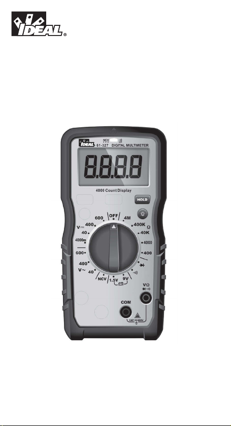
61-327 Multimeter
Operation and Safety Manual
TestEquipmentDepot.com
Instrucciones en español adentro / Instructions en français à l’intérieur
Page 2

Table of Contents
Introduction ................................................................... 3
Contacting IDEAL INDUSTRIES, INC ...................................... 3
Safety Information ........................................................... 4
Warnings .............................................................................................. 4-5
Cautions ...................................................................................................5
Symbols ............................................................................................... 6-7
Operation.................................................................. 8-19
Identification and description of operating controls and
functions ............................................................................................. 8-9
Operating Features ........................................................................... 10-11
Using Test Leads ....................................................................................12
Meter Operation .............................................................................. 13-16
Non-Contact Voltage Testing ..........................................................13
Measuring Voltage .........................................................................14
Measuring Continuity .....................................................................15
Measuring Resistance ....................................................................15
Measuring Diodes ..........................................................................16
Testing a Battery .............................................................................16
Functions Operation Table ......................................................................17
Functions Indication Table .....................................................................18
Electrical Specifications .........................................................................19
Environmental Specifications .............................................20
Mechanical Specifications ................................................20
EMC / EMI ....................................................................20
FCC .........................................................................21
Safety .........................................................................21
Maintenance and Service .............................................22-23
2
Page 3

Introduction
®
The IDEAL
that measures voltage, resistance, continuity, diodes and performs a battery check
via test-leads in the designated terminals. It also detects the presence of voltage
between 40V to 600V AC via a non-contact sensor in the top center of the meter.
61-327 Digital Multimeter is a manual ranging average RMS meter
Arc Flash and Shock Hazard, Proper PPE Required. Follow all safety procedures,
wear proper PPE in accordance to NFPA 70E. Read and fully understand the
instruction manual prior to using this product. Failure to comply can result in
serious injury or death.
3
Page 4
Safety Information
Warning - Identifies conditions and actions that could result in
possible death or serious injury if the hazard is realized.
Caution - Identifies conditions and actions that could result in meter damage, equipment under test damage or data loss if the hazard is realized.
WARNING
Arc Flash and Shock Hazard, Proper PPE Required. Follow all safety procedures,
wear proper PPE in accordance to NFPA 70E and follow the guidelines below and the
instructions in this manual when operating the meter. Failure to comply can result in
serious injury or death.
• Choking Hazard, Small Parts. Keep Away from Children. Sharp Objects
Hazard, This is not a toy. It is not for use or play by children. Keep Away
from Children. Failure to do so can result in serious injury.
• Only experienced or technically competent consumers should use this
equipment. When in doubt, call an experienced electrician to make any and
all necessary repairs or installations. At all times, perform any necessary
work on a de-energized circuit that has had its circuit breaker turned off and
has been locked out.
• Use the Meter only as specified in this manual or protection provided by the
Meter can be compromised.
• Before using or connecting the Meter, visually inspect it to ensure the cases
are not cracked and the back case is securely in place. Do not use if the
Meter appears damaged.
• Before using the test leads, inspect carefully for damaged insulation,
exposed metal or cracked probes. Check test leads for continuity. Do not use
leads if they appear damaged.
• Use only approved test leads. Do not use improvised connections that could
present a safety hazard.
• When using the probes, keep fingers behind the guard ring on the probes.
• Connect the common test lead before connecting the live test lead. When
disconnecting test leads, disconnect the live test lead first.
• This Meter is intended for use by qualified electricians. Follow NFPA 70E
Standards for Electrical Safety in the Workplace when using this Meter.
• Do not use without the batteries correctly in place and the battery door
closed and secured.
• Do not use Meter if it operates incorrectly as protection may be
compromised. When in doubt, have the Meter serviced.
• When servicing the Meter, use only specified replacement parts.
4
Page 5
WARNING
Arc Flash and Shock Hazard, Proper PPE Required. Follow all safety procedures,
wear proper PPE in accordance to NFPA 70E and follow the guidelines below and
the instructions in this manual when operating the meter. Failure to comply can
result in serious injury or death.
• Have the Meter serviced only by qualified service personnel.
• Do not use the Meter around explosive gas, dust, or vapor, or during electrical
storms, or in wet environments.
• When measuring, keep fingers behind the Tactile Barrier. See “The Meter” on
pg. 8 and 9.
• Do not apply more than the rated voltage, as marked on the Meter, between the
terminals or between any terminal and earth ground.
• To avoid false readings that can lead to electrical shock and injury, replace the
batteries as soon as the low battery indicator ( ) appears.
• Remove the test leads from the circuit prior to removing the battery door.
• Voltages exceeding 30VAC or 60VDC pose a shock hazard so use caution.
• Always ensure that test leads are secured so that they cannot be accidentally
snagged or tripped over.
• Do not work alone so that assistance can be rendered in an emergency.
• Use extreme caution when working around bare conductors or bus bars. Contact
with the conductor could result in electric shock.
• Adhere to local and national safety codes. Individual protective equipment must
be used to prevent shock and arc blast injury where hazardous live conductors
are exposed.
• Disconnect circuit power and discharge all high-voltage capacitors before you
measure resistance, continuity, or capacitance.
•
Never operate the Meter with the back cover removed or the case open.
o Cancer and Reproductive Harm
CAUTION
Meter damage, equipment under test damage or data loss can occur
if the following guidelines are not adhered to.
• Use the proper terminals, function, and range for the measurement
application.
• Clean the case and accessories with a damp cloth and mild detergents only.
Do not use abrasives or solvents. Make sure the meter is completely dry
before use.
5
Page 6
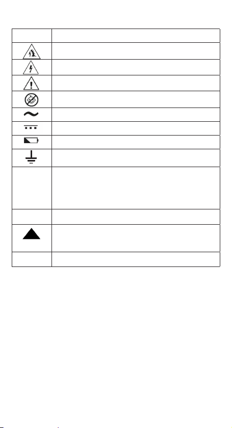
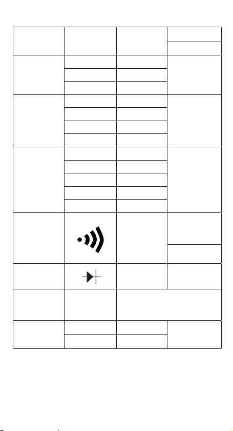
Symbols & Descriptions
SYMBOL DESCRIPTION
Arc Flash and Shock Hazard
Shock Hazard
Warning or Caution
Choking Hazard
AC (Alternating Current)
DC (Direct Current)
Low Battery Indicator
Earth Ground
CAT III
NCV
IEC Measurement Category III
CAT III has protection against transients in equipment in fixedequipment installations such as distribution panels feeders,
and short branch circuits. Also included are lighting systems in
larger buildings.
Non-Contact Voltage Sensing
Non-Contact Voltage Sensing Point
NCV
Voltage AC or DC
V
6
Page 7

SYMBOL DESCRIPTION
Ohms
Ω
Continuity
Diode
1.5 and 9V DC Battery Test
LCD Liquid Crystal Display
Range Manual Range Selection
Do not dispose of this product as unsorted municipal waste.
It must be properly disposed of in accordance with local
regulations.
Conforms to applicable North American Safety Standards
Conforms to applicable Australian Safety Standards
Conforms to European Directives
NOTE: The Measurement Category (CAT) and voltage rating of any combination
of test probe, test probe accessory, current clamp accessory, and the Meter is the
LOWEST rating of any individual component.
7
Page 8

Operation
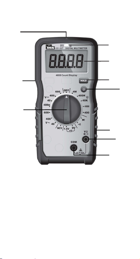
Identification and Description of Operating
Controls and Functions for the 61-327 Digital
Multimeter:
1. HV, & Continuity LED
2. LCD Display
3. Tactile Barrier
4. Backlight Button
5. Hold Button
6. Rubber Boot
7. Volts/Ohms Input Terminal
8. Common (COM) Input Terminal
9. Manual Measuring Functions Dial
10. NCV Sensing Point
8
Page 9
10
1
2
3
5
4
9
6
7
8
9
Page 10

Operating Features
High Voltage Warning (HI-V)
The meter beeps once (for 1 second) and a red LED illuminates and remains on as
long as the voltage remains above 30V AC or DC, or when the meter’s voltage range
is exceeded.
NOTE: This feature does not work in the Ohm or continuity modes. For ACV and
DCV, when voltages in excess of 30V is measured or the measured voltage is over
limit, then the high voltage alarm ‘ .’ appears on the screen display,
simultaneously the LED remains RED and beeping lasts for 1 second then silent
during measurement.
Data Hold Feature
Press the Hold button to toggle in and out of the data hold mode. “H” appears in the
upper left of the meter display when data hold is active. Use the data hold feature to
lock a measurement reading on the display. Press the Hold button again to unlock
the display and obtain a real-time reading.
Auto Power Off (APO) Feature Disable
The meter automatically powers itself down after about 30 minutes of no use. Press
any button, and the meter will wake up and enter the default function of that setting
before power down. To Disable APO, press and hold the HOLD button while turning
the dial to any desired function. When APO is defeated, the “APO” will be removed
from the display. Turning the meter off and back on will restore the APO default.
10
Page 11
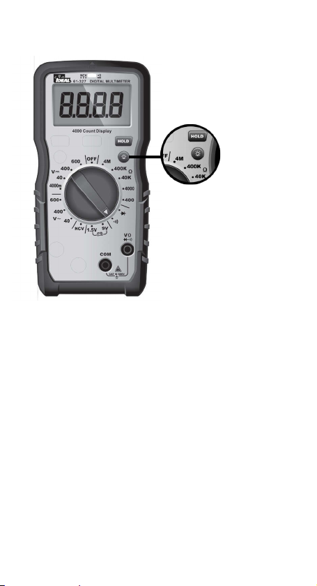
Backlight
Backlight is selectable
to be on in all
functions.
Press the BACKLIGHT button on the meter to turn the backlight on and off. The
white backlight will remain lit for about 5 minutes before it automatically turns off
to conserve battery power. Or turn the backlight off by pressing the button again.
11
Page 12
Using Test Leads
WARNING: Arc Flash and Shock Hazard, Proper PPE Required.
Follow all safety procedures, wear proper PPE in accordance to NFPA 70E and
follow the guidelines below and the instructions in this manual when operating
the meter with TL-757 Test Leads or equivalent. Test Leads must be rated for the
electrical environment the meter is being used in and have a voltage rating of at
least the voltage of the circuit to be measured. Failure to comply can result in
serious injury or death.
• Choking Hazard, Small Parts. Keep Away from ...
Children. Sharp Objects Hazard, This is not a toy. It is not for use or
play by children. Failure to do so can result in serious injury or death.
• Use only approved test leads. Do not use improvised connections that could
present a safety hazard.
• Ensure that the test leads are inserted into the correct input jacks when
measuring AC or DC current.
• Prior to using the test leads, inspect them carefully for damaged insulation,
exposed metal or bent probes. Check test leads for continuity. Do not use
leads if they appear damaged.
• When using the probes, keep fingers behind the guard rings on the probes.
• Connect the common test lead before connecting the live test lead. When
disconnecting test leads, disconnect the live test lead first.
• Always ensure that test leads are secured so that they cannot be accidentally
snagged or tripped over.
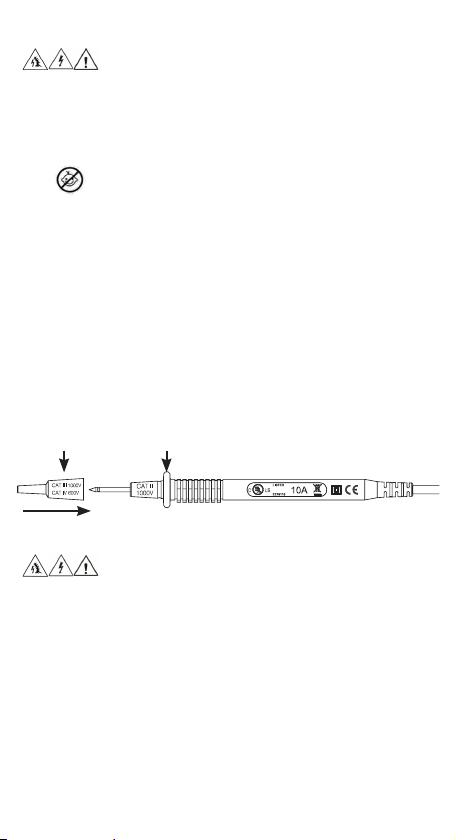
Protective Cap Guard Ring
Note: The 61-327 is only rated to 600V AC or DC MAX
WARNING: Arc Flash and Shock Hazard, Proper PPE Required.
Follow all safety procedures, wear proper PPE in accordance to NFPA 70E and
assure that the Protective Caps are in place when operating a properly rated
electrical meter/tester using the TL-757 Test Leads in a CAT IV 600V or CAT III
1000V environment.
This meter is intended for use with the IDEAL TL-757 lead set (provided with this
product) or equivalent. The lead set must comply with requirements for Overvoltage
and Measurement Categories CAT IV 600V CAT III 1000V.
This meter is CAT III 600V ONLY
12
Page 13
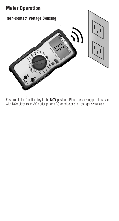
Meter Operation
Non-Contact Voltage Sensing
First, rotate the function key to the NCV position. Place the sensing point marked
with NCV close to an AC outlet (or any AC conductor such as light switches or
power cords) and scan back and forth across the outlet. The meter beeps On/Off
continuously and the Red NCV LED above the display flashes if the sensing antenna
detects live voltage greater than 40V AC (50 -60 Hz). Voltages with frequencies
higher than 60Hz or electrostatic charges may also be detected by the NCV sensing
antenna. To differentiate between hot and neutral in an outlet, place the NCV tab
directly next to each slot in the outlet. The tone (buzzer) will sound over the slot
that is energized and not on the neutral slot. Either test lead can also be used to
differentiate between the hot and neutral. Plug the red or black test lead into the
V input jack on the meter. With the function switch in the NCV position, insert the
probe end of just one probe into the slots on the outlet. The meter will beep and the
Red LED will flash when a hot conductor is contacted.
NOTE: While the NCV is a helpful function, it is ALWAYS
RECOMMENDED that the operator verify that any electrical conductor is
completely de-energized and that no voltage is present by measuring
for voltage AND CONFIRMING THAT NO VOLTAGE IS PRESENT and that
all applicable PPE and lock out tag out procedures be followed before
attempting any work on ANY electrical distribution system.
13
Page 14
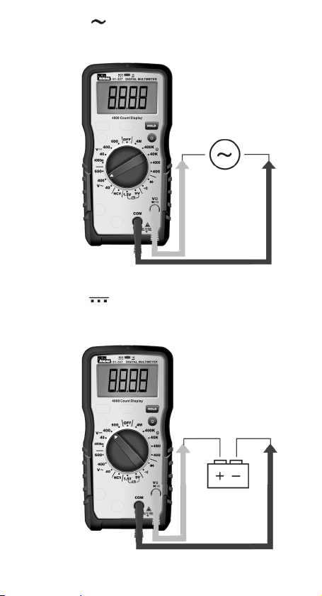
Measuring AC ( ) Voltage Manually Select Range From
00.00 to 40V-600V
Measuring DC ( ) Voltage Manually Select Range From
0000mV to 4000mV-600V
14
Page 15
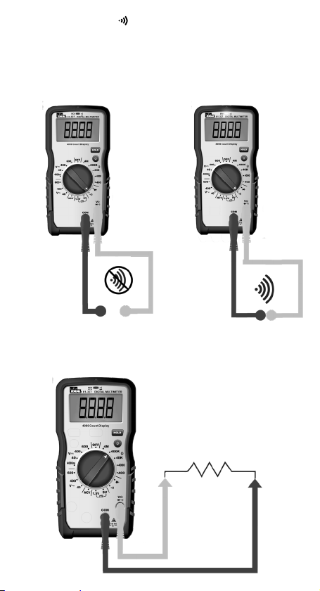
Verifying Continuity ( )
• Verify the circuit is de-energized.
• The meter will sense the level of resistance and beep if the resistance is less
than 10 Ω’s to confirm that continuity is present.
• The red LED will illuminate and the resistance value will be displayed.
Measuring Resistance (Ohms / Ω) Manually Select Range
From 00.0 to 400-4MEG Ohms
Verify the circuit is de-energized to obtain accurate measurements.
15
Page 16
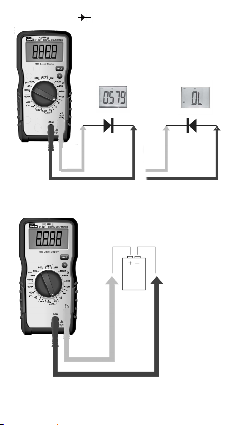
Measuring Diodes ( )
Testing a Battery
16
Page 17

Functions Operation Table
Button Response
HOLD: All
HOLD
Functions
Non-Contact Voltage Indication
Backlight
Default
Function
Normal
Measurement
OFF
Operation
Short Press: Circularly enter or exit
the data hold mode, LCD will display
“ ” after
enter HOLD function.
Short Press: Circularly enter or exit
the backlight mode
Displays “EF” – Electromagnetic
Field
17
Page 18
Functions Indication Table
Function Description
LCD One LCD. Displays a “-” symbol for all negative readings, displays “AC” for
LCD
Backlight
High
Voltage
Alarm
Regular
Prompt
Over Range
Indication
Low Battery
Indication
APO The unit will be automatically power off after 30 minutes of inactivity and
Restore
APO
Disable
Auto Power
Off Function
Mechanical
Housing
alternating current or “DC” for direct current.
White backlight. The backlight will automatically power off after 5 minutes
of inactivated
1) Only applicable to ACV / DCV
2) For ACV and DCV, when voltages in excess of 30V is measured or the
measured voltage is over limit, then the high voltage alarm symbol “ .”
appears on the screen display, simultaneously the LED remains RED and
beeping lasts for 1 second then becomes silent during measurement.
1) When turning the dial switch to any setting position except OFF, the buzzer
will beep one time and the NCV LED flashes one time.
2) When the button selection is valid, the buzzer will beep one time; When the
button is invalid, the buzzer will beep twice.
3) About 1 minute before the automatic shutdown, the buzzer will beep 5
times continuously, and 1 long beep before the unit shuts down.
4) When the automatic shutdown function is canceled, the buzzer will beep 5
times when it reaches the APO time setting.
LCD displays “OL” when over range is encountered.
When the battery voltage < 3.6 ±0.2V, the low battery indication ‘ ‘ is
displayed on the screen and the meter will still work normally. When the
battery voltage drops to less than 3.1 ±0.2V, “bAtt” is displayed for 5 seconds
then shuts off. When the battery voltage is less than 2.3V, accuracy is no
longer assured.
enter the low-power state. Current draw is approx. ≤50 micro A.
All the buttons can wake up the unit, rotate the dial switch to any setting
except OFF to wake it up.
Pressing the “HOLD” key while turning on the unit on at the same time, will
cancel the auto shutdown function. Buzzer will beep 5 times and the LCD will
not display the “APO” symbol.
Single Injection Molding with rubber boot.
18
Page 19
Electrical Specifications
Function Range
AC Voltage (V)
ARMS
DC Voltage (V)
Resistance (Ω)
Continuity 0.1 Ω
Diode test 0.001V
NCV 40-600V
BAT
61-327
40.00V 0.01V
600.0V 1.0V
4000mV 1mV
40.00V 0.01V
400.0V 0.1V
600.0V 1.0V
400.0Ω 0.1Ω
4000Ω 1Ω
40.00kΩ 0.01kΩ
400.0kΩ 0.1kΩ
4.000MΩ 0.001MΩ
1.5V
9V
Resolution Accuracy
≥40V/(50~60Hz), with direct wire contact,
red indicator LED flashes at a frequency of
3Hz , and the buzzer beeps at a frequency of
3Hz simultaneously
0.001V
0.01V
±(a%+b)
±(1.3%+5)400.0V 0.1V
±(1.3%+5)
±(1.5%+5)
≤10Ω : Buzzer beeps
and red indicator
LED illuminates
continuously
≥70Ω : No buzzer
beep
Silicon PN joint
with forward voltage
about 0.5V to 0.8V
±(1.3%+5)
1. Overload Protection: 600VRMS
2. Accuracy a is % of reading and b is LSD (Least Significant Digit).
19
Page 20

Environmental Specifications
Operating Temperature:
32ºF to 86ºF (0ºC to 30ºC) (80%RH)
86ºF to 140ºF (30ºC to 40ºC) (75%RH)
104ºF to 122ºF (40ºC to 50ºC) (45%RH)
Operating Altitude:
Storage Temperature:
Intended for indoor use
< 6500 ft (< 2000 m)
14ºF to 140ºF (-10ºC to 60ºC) (<80%RH)
Mechanical Specifications
Dimensions (L x W x H) 6.54 in. x 3.23 in. x 1.89 in.
Weight 0.62 LBS (0.28 KG)
Display: LCD
Display Count 4000
Power Source: 3 x 1.5V AAA
Battery Life: 100 Hours Typical
(166 mm. x 82 mm. x 48 mm.)
EMC/EMI
CISPR 22 3rd Edition. Class B Limits.
EN 55032
CISPR 32
CISPR 11
FCC 15. 107 with reference to Section 15.109 (g).
ICES-003
EN 61326-2-2 Sec 6.4.2.101
20
Page 21

USA (FCC)
47 CFR 15 subpart B. This product is considered an exempt device per clause
15.103.
Safety
Complies with the following:
UL 61010-1, 3rd Edition, May 11, 2012, Revised November 21 2018, CAN/
CSA-C22.2 No. 61010-1-12, 3rd Edition, Amendment 1:2018, Revision dated
November 21 2018,
IEC 61010-2-033: 2019
Overvoltage CAT III 600V
Any voltages exceeding the defined maximum voltage measurement categories
described above are outside the normal use of the equipment and protection cannot
be guaranteed.
Pollution Degree Class 2
21
Page 22
Maintenance and Service
Equipment Maintenance and Service
Meter Inspection
Do not use if meter appears damaged. Visually inspect the meter to ensure the case
is not cracked.
Test Lead Inspection
Inspect and replace test leads if insulation is damaged, metal is exposed, or probes
are cracked. Pay particular attention to the insulation surrounding the connectors.
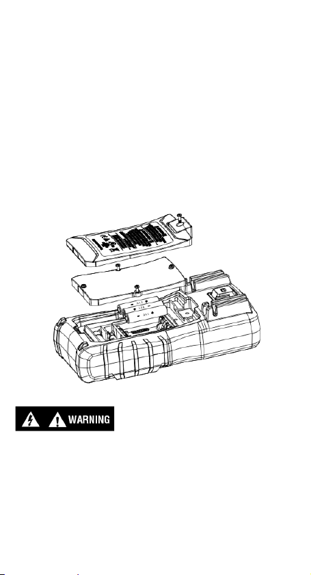
Battery Inspection/Replacement
Inspect the battery compartment monthly for any signs of degradation. Low battery
voltages will cause inaccuracies in readings. Remove the batteries for storage
or if the meter will not be used for longer than one month. Battery leakage will
compromise the safety of the meter and cause irreparable damage to internal
components.
Shock Hazard. Remove the test leads from the circuit prior to removing the battery
cover. Failure to comply can result in serious injury or death.
Maintenance and Storage
Switch off and disconnect the meter completely before carrying out any
maintenance. Clean the case with a damp cloth and mild detergent. Do not use
abrasives or solvents. Keep away from liquids and ensure the meter is completely
dry before use.
Service and Replacement Parts
This unit has no user-serviceable parts.
22
Page 23

Disposal of Waste, Electrical & Electronic Equipment
In order to preserve, protect and improve the quality of the environment, protect
human health and utilize natural resources prudently and rationally, the user
should return unserviceable product to relevant facilities in accordance with
statutory regulations. The crossed-out wheeled bin indicates the product needs to
be disposed separately and not as municipal waste.
Do not dispose of this product as unsorted municipal waste. It must be properly
disposed of in accordance with local regulations.
Disposal of Used Batteries/Accumulators
The user is legally obliged to return used batteries and accumulators. Disposing
used batteries in household waste is prohibited! Batteries/accumulators containing
hazardous substances are marked with the crossed-out wheeled bin. The symbol
indicates that the product is forbidden to be disposed via domestic refuse. The
chemical symbols for the respective hazardous substances are Cd = Cadmium, Hg
= Mercury, Pb = Lead.
You can return used batteries/accumulators free of charge to any collecting point of
your local authority, our stores, or where batteries/accumulators are sold.
Consequently, you must comply with your legal obligations and contribute to
environmental protection.
TWO YEAR LIMITED WARRANTY
This tester is warranted to the original purchaser against defects in material and
workmanship for a period of two (2) years from date of purchase. With proof of
purchase from an authorized IDEAL distributor, a defective tester will be repaired or
replaced with the same product or a functionally equivalent product, at the option of
IDEAL INDUSTRIES, INC. during the warranty period, subject to verification
of the defect or malfunction. Warranty does not cover consumables such as fuses,
batteries, and excludes defects caused by leakage from batteries, abuse,
mishandling, dropping, ordinary wear and tear, misuse, neglect, unauthorized
repair, improper use, alterations, accidents or any causes beyond IDEAL’s
reasonable control. Consequential or incidental damages are not recoverable under
this warranty. Some states do not allow the exclusion or limitation of incidental or
consequential damages, so the above limitation or exclusion may not apply to you.
This LIMITED WARRANTY gives you specific legal rights, which vary from state to
state. This warranty constitutes the sole and exclusive remedy of the purchaser and
the exclusive liability of IDEAL, and is in lieu of any and all other warranties, and
expressly disclaims all other warranties, implied, or statutory as to merchantability,
fitness for purpose sold, description, quality productiveness, or any other matter.
No agent, distributor or other supplier has the authority to modify or amend this
warranty or make other representations or warranties other than those contained in
this warranty without express written authorization from IDEAL. For warranty
service, call IDEAL customer service at 1-800-435-0705.
Made in China.
23
Page 24

Escanee el código de barras a la derecha para ver la nueva Línea de Productos IDEAL T&M
Page 25

IDEAL® Prueba y Medición
Medidor 61-327
Manual de Operación y Seguridad
Instrucciones en español adentro / Instructions en français à l’intérieur
Page 26

Índice
Introducción .................................................................27
Cómo contactar a IDEAL INDUSTRIES, INC. ............................28
Información de Seguridad .................................................29
Advertencias .....................................................................................28-29
Precauciones ..........................................................................................29
Símbolos ..........................................................................................30-31
Operación .............................................................. 8-19
Identificación y descripción de controles de operación y funciones . 32-33
Funciones de Operación ...................................................................34-35
Uso de los Cables de Prueba .................................................................36
Operación del Medidor .....................................................................37-40
Prueba de Voltaje Sin Contacto ..................................................37
Medición de Voltaje ...................................................................38
Medición de Continuidad ...........................................................39
Medición de Resistencia ............................................................39
Medición de Diodos ...................................................................40
Prueba de Una Batería ................................................................40
Tabla de Operaciones de Funciones .......................................................41
Tabla de Indicación de Funciones ..........................................................42
Especificaciones Eléctricas ...............................................43
Especificaciones Ambientales ............................................44
Especificaciones Mecánicas ..............................................44
EMC/EMI......................................................................44
FCC ............................................................................45
Seguridad ....................................................................45
Mantenimiento y Servicio .............................................46-47
26
Page 27

Introduction
El Multímetro Digital IDEAL® 61-327 es un medidor RMS promedio de
rango manual que mide voltaje, resistencia, continuidad, diodos y realiza
una comprobación de batería a través de cables de prueba en los terminales
designados. También detecta la presencia de voltaje entre 40V a 600V CA a través
de un sensor sin contacto en la parte superior central del medidor.
Peligro de Arco Eléctrico y Descarga Eléctrica, se Requiere el EPP Adecuado. Siga
todos los procedimientos de seguridad, use el EPP adecuado de acuerdo con NFPA
70E. Lea y comprenda completamente el manual de instrucciones antes de usar
este producto. El incumplimiento puede resultar en lesiones graves o la muerte.
27
Page 28

Información
Advertencia - Identifica condiciones y acciones que podrían
provocar la muerte o lesiones graves si se toma el riesgo.
Precaución - Identifica condiciones y acciones que podrían resultar en
daño al medidor, daño al equipo bajo prueba o pérdida de datos si se toma el
riesgo.
WARNING
Peligro de Arco Eléctrico y Descarga Eléctrica, se Requiere el EPP Adecuado. Siga
todos los procedimientos de seguridad, use el EPP adecuado de acuerdo con NFPA
70E y siga las pautas a continuación y las instrucciones de este manual cuando
opere el medidor. El incumplimiento puede resultar en lesiones graves o la muerte.
• Peligro de Asfixia, Partes Pequeñas. Mantener Fuera del Alcance de
los Niños.
• Peligro de Objetos Afilados, Esto no es un juguete. No es para uso o juego
de niños. Mantener Fuera del Alcance de los Niños. No hacerlo puede
resultar en lesiones graves.
• Solo los consumidores experimentados o técnicamente competentes deben
utilizar este equipo. En caso de duda, llame a un electricista experimentado
para que realice todas las reparaciones o instalaciones necesarias. En todo
momento, realice cualquier trabajo necesario en un circuito desenergizado
al que se le haya apagado el cortacircuitos y se haya bloqueado.
• Utilice el Medidor solo como se especifica en este manual o la protección
proporcionada por el Medidor puede verse comprometida.
• Antes de usar o conectar el Medidor, revíselo visualmente para asegurarse
de que las carcasas no estén agrietadas y que la carcasa posterior esté bien
colocada. No use el Medidor sí parece dañado.
• Antes de usar los cables de prueba, revíselos cuidadosamente para detectar
daños en el aislamiento, metal expuesto o sondas rajadas. Compruebe las
puntas de prueba para verificar si hay continuidad. No utilice los cables sí
parecen dañados.
• Utilice solo cables de prueba aprobados. No utilice conexiones
improvisadas que puedan representar un peligro para la seguridad.
• Cuando utilice las sondas, mantenga los dedos detrás del anillo de
protección de las sondas.
• Conecte el cable de prueba común antes de conectar el cable de prueba con
corriente. Al desconectar los cables de prueba, desconecte primero el cable
de prueba con corriente.
• Este Medidor está diseñado para ser usado por electricistas calificados.
Siga las Normas NFPA 70E para Seguridad Eléctrica en el lugar de trabajo
cuando utilice este Medidor.
• No lo utilice sin las baterías correctamente colocadas y la tapa de las
baterías cerrada y asegurada.
• No utilice el Medidor si funciona incorrectamente, ya que la protección
puede verse comprometida. En caso de duda, lleve el Medidor a que le
hagan servicio.
• Al realizar el servicio al Medidor, use solo los repuestos especificados.
28
Page 29

ADVERTENCIA
Peligro de Arco Eléctrico y Descarga Eléctrica, se Requiere el EPP Adecuado. Siga
todos los procedimientos de seguridad, use el EPP adecuado de acuerdo con NFPA
70E y siga las pautas a continuación y las instrucciones de este manual cuando
opere el medidor. El incumplimiento puede resultar en lesiones graves o la muerte.
• Únicamente permita que el servicio del Medidor lo lleve a cabo personal de
servicio calificado.
• No utilice el Medidor cerca de gases, polvo o vapores explosivos, o durante
tormentas eléctricas o en entornos húmedos.
• Al medir, mantenga los dedos detrás de la Barrera Táctil. Consulte “El Medidor”
en la pág. 32 y 33.
• No aplique voltaje por encima del voltaje nominal, según lo indicado en el
Medidor, entre las terminales o entre cualquier terminal y conexión a tierra.
• Para evitar lecturas falsas que pueden provocar descargas eléctricas y lesiones,
reemplace las baterías tan pronto como aparezca el indicador de baterías bajas
( ).
• Retire los cables de prueba del circuito antes de quitar la tapa de las baterías.
• Los voltajes que excedan los 30VCA o 60VCD representan un peligro de
descarga eléctrica, así que tenga cuidado.
• Asegúrese siempre de que los cables de prueba estén asegurados para que no
puedan ser enganchados accidentalmente o causen tropiezos.
• No trabaje solo para que se pueda prestar asistencia en caso de emergencia.
• Tenga mucho cuidado al trabajar cerca de conductores pelados o barras
colectoras. El contacto con el conductor podría provocar una descarga eléctrica.
• Cumpla con los códigos de seguridad locales y nacionales. Se debe utilizar
equipo de protección individual para evitar descargas eléctricas y lesiones por
explosión de arco cuando se exponen conductores activos peligrosos.
• Desconecte la alimentación del circuito y descargue todos los capacitores de
alto voltaje antes de medir la resistencia, la continuidad o la capacitancia.
• Nunca opere el Medidor con la cubierta trasera removida o la carcasa abierta.
• Cáncer y Daño Reproductivo
PRECAUCIÓN
Daño al Medidor, daño al equipo bajo prueba o la pérdida de los datos puede ocurrir
si no se siguen las siguientes pautas..
• Utilice las terminales, la función, y el rango apropiado para la aplicación de
la medida.
• Únicamente limpie la carcasa y los accesorios con un paño húmedo y
detergentes suaves. No utilice abrasivos o solventes. Asegúrese de que el
medidor esté totalmente seco antes de usar.
29
Page 30

Símbolos y Descripciones
SÍMBOLO DESCRIPCIÓN
Peligro de Arco Eléctrico y Descarga Eléctrica
Peligro de Descarga Eléctrica
Advertencia o Precaución
Peligro de Asfixia
CA (Corriente Alterna)
CD (Corriente Directa)
Indicador de Carga de la Batería
Tierra
CAT III
NCV
Categoría de Medición IEC III
CAT III tiene protección contra transitorios en equipos en
instalaciones de equipos fijos como paneles de distribución,
alimentadores y circuitos derivados cortos. También se incluyen
sistemas de iluminación en edificios más grandes.
Detección de Voltaje Sin Contacto
Punto de Detección de Voltaje Sin Contacto
NCV
Voltaje CA o CD
V
30
Page 31

SÍMBOLO DESCRIPCIÓN
Ohmios
Ω
Continuidad
Diodo
Prueba de batería de 1,5 y 9 V CC
LCD Pantalla de Cristal Líquido
Range Selección Manual de Rangos
No elimine este producto como residuo municipal sin clasificar.
Debe desecharse adecuadamente de acuerdo con las regulaciones locales.
Cumple con los Estándares de Seguridad Norteamericanos
aplicables
Cumple con los Estándares de Seguridad Australianos
aplicables
Cumple con las Directivas Europeas
NOTA: La Categoría de Medición (CAT) y la clasificación de voltaje de cualquier
combinación de sonda de prueba, accesorio de sonda de prueba, accesorio
de pinza de corriente y el Medidor es la clasificación MÁS BAJA de cualquier
componente individual.
31
Page 32

Operación
Identificación y Descripción de Controles y
Funciones Operativos para el Medidor Digital
61-327:
1. LED de HV y Continuidad
2. Pantalla LCD
3. Barrera Táctil
4. Botón de Luz de Fondo
5. Botón de Retención
6. Bota de Goma
7. Terminal de Entrada de Voltios/Ohmios
8. Terminal de Entrada Común (COM)
9. Selector de Función de Medición Manual
10. Punto de Detección de NCV
32
Page 33

10
1
2
3
5
4
9
6
7
8
33
Page 34

Funciones de Operación
Advertencia de Alto Voltaje (HI-V)
EEl medidor emite un pitido (durante 1 segundo) y un LED rojo se ilumina y
permanece encendido mientras el voltaje permanezca por encima de 30V CA o CD,
o cuando se excede el rango de voltaje del medidor.
NOTA: Esta función no trabaja en los modos de Ohmios o continuidad. Para VCA
y VCD, cuando se miden voltajes superiores a 30V o el voltaje medido está por
encima del límite, entonces el símbolo de alarma de alto voltaje “ “ aparece en
la pantalla, simultáneamente el LED permanece ROJO y el pitido
dura 1 segundo y luego se vuelve silencioso durante la medición.
Función de Retención de Datos
Presione el botón HOLD en el costado del medidor para alternar dentro y fuera del
modo de retención de datos. “HOLD” aparece en la parte superior izquierda de la
pantalla del medidor cuando la retención de datos está activa. Utilice la función
de retención de datos para fijar una lectura de medición en la pantalla. Presione el
botón Hold de nuevo para desbloquear la pantalla y obtener una lectura en tiempo
real.
Desactivación de la Función de Apagado Automático (APO)
El medidor se apaga automáticamente después de unos 30 minutos sin uso. Pulse
cualquier botón, y el medidor se activará y mostrará la última lectura tomada antes
de apagarse. Para desactivar APO, presione y mantenga presionado el botón SEL
mientras gira el selector a la función deseada. Cuando se desactiva el APO, el
“APO” será quitado de la pantalla. Apagar y volver a encender el medidor restaurará
la preconfiguración APO.
34
Page 35

Luz de Fondo
La luz de fondo se
puede seleccionar para
estar activada en todas
las funciones.
Presione el botón BACKLIGHT en el medidor para encender y apagar la luz de
fondo.. La luz de fondo blanca permanecerá encendida durante unos 5 minutos
antes de que se apague automáticamente para conservar la energía de las baterías.
O apague la luz de fondo presionando el botón de nuevo.
35
Page 36

Uso de los Cables de Prueba
Protective Cap Guard Ring
ADVERTENCIA: Peligro de Arco Eléctrico y Descarga Eléctrica,
se Requiere el EPP Adecuado. Siga todos los procedimientos de seguridad, use
el EPP adecuado de acuerdo con NFPA 70E y siga las pautas a continuación y las
instrucciones de este manual cuando opere el medidor con los Cables de Prueba
TL-575 o equivalentes. Los Cables de Prueba deben estar clasificados para el
entorno eléctrico en el que se utiliza el medidor y tener un voltaje nominal de al
menos el voltaje del circuito que se va a medir. El incumplimiento puede resultar en
lesiones graves o la muerte.
• Peligro de Asfixia, Partes Pequeñas. Mantener alejado de
Niños. Peligro de Objetos Afilados, Esto no es un juguete. No es para uso o
juego de niños. No hacerlo puede resultar en lesiones graves o la muerte.
• Utilice solo cables de prueba aprobados. No utilice conexiones
improvisadas que puedan representar un peligro para la seguridad.
• Asegúrese de que los cables de prueba estén insertados en las tomas de
entrada correctas al medir la corriente CA o CD.
• Antes de usar los cables de prueba, revíselos cuidadosamente para detectar
daños en el aislamiento, metal expuesto o sondas dobladas. Compruebe las
puntas de prueba para verificar si hay continuidad. No utilice los cables sí
parecen dañados.
• Cuando utilice las sondas, mantenga los dedos detrás de los anillos de
protección en las sondas.
• Conecte el cable de prueba común antes de conectar el cable de prueba
con corriente. Al desconectar los cables de prueba, desconecte primero el
cable de prueba con corriente.
• Asegúrese siempre de que los cables de prueba estén asegurados para que
no puedan ser enganchados accidentalmente o causen tropiezos.
Cubierta Protectora Anillo Protector
Nota: El 61-327 solo está clasificado para 600 V CA o CC MAX
ADVERTENCIA: Peligro de Arco Eléctrico y Descarga Eléctrica,
se Requiere el EPP Adecuado. Siga todos los procedimientos de seguridad, use un
EPP adecuado de acuerdo con NFPA 70E y asegúrese de que las Tapas Protectoras
estén en su lugar cuando utilice un medidor/probador eléctrico debidamente
clasificado utilizando los Cables de Prueba TL-757 en un entorno CAT IV 600V o
CAT III 1000V.
Este medidor es CAT III 600V SOLAMENTE
36
Page 37

Operación del Medidor
Detección de Voltaje Sin Contacto
Primero, gire la tecla de función a la posición NCV. Coloque la punta de detección
marcada con NCV cerca de una toma de CA (o cualquier conductor de CA, como
interruptores de luz o cables de alimentación) y escanee hacia adelante y hacia
atrás a través de la toma. El medidor emite un pitido de En/Apagado continuo y el
LED Rojo de NCV sobre la pantalla parpadea si la antena de detección detecta un
voltaje vivo superior a 40V CA (50-60 Hz). La antena de detección NCV también
puede detectar voltajes con frecuencias superiores a 60 Hz o cargas electrostáticas.
Para diferenciar entre caliente y neutro en un tomacorriente, coloque la pestaña
NCV directamente al lado de cada ranura del tomacorriente. El tono (zumbador)
sonará sobre la ranura que está energizada y no en la ranura neutral. Cualquiera
de los cables de prueba también se puede utilizar para diferenciar entre el caliente
y el neutro. Enchufe el cable de prueba rojo o negro en el enchufe de entrada V del
medidor. Con el selector de función en la posición NCV, inserte el extremo de la
sonda de una sola sonda en las ranuras de la salida. El medidor emitirá un pitido y
el LED rojo parpadeará cuando se contacte con un conductor caliente.
NOTA: Si bien el NCV es una función útil, SIEMPRE SE RECOMIENDA
que el operador verifique que cualquier conductor eléctrico esté
completamente desenergizado y que no haya voltaje presente
midiendo el voltaje Y CONFIRMANDO QUE NO HAY VOLTAJE PRESENTE
y que todos los EPP y los procedimientos de bloqueo y de etiquetado
aplicables se sigan antes de intentar cualquier trabajo en CUALQUIER
sistema de distribución eléctrica.
37
Page 38

Medición de Voltaje CA ( ) Seleccione Manualmente el
Rango de 00.00 a 40V-600V
Medición Voltaje CD ( ) Seleccione Manualmente el
Rango De 0000mV a 4000mV-600V
38
Page 39

Verificar Continuidad ( )
• Verifique que el circuito esté desenergizado.
• El medidor detectará el nivel de resistencia y emitirá un pitido si la resistencia
es inferior a 10 Ω’s para confirmar que hay continuidad.
• El LED rojo se iluminará y se mostrará el valor de resistencia.
Medición de Resistencia (Ohmios/Ω ) Seleccione
Manualmente el Rango de 00.0 a 400-4MEG Ohmios
Verifique que el circuito esté desenergizado para obtener mediciones precisas.
39
Page 40

Medición de Diodos ( )
Prueba de Una Batería
40
Page 41

Tabla de Operaciones de Funciones
Botón Respuesta
RETENCIÓN:
RETENCIÓN
Indicación de Voltaje Sin Contacto
Todas las
funciones
Luz de
Fondo
Función
Predeterminada
Medición Normal
APAGADO
Operación
Pulsación Corta: Entrar o salir
circularmente del modo de retención
de datos, LCD mostrará “ ”
después de entrar en la
función de RETENCIÓN.
Pulsación Corta: Entrar o salir
circularmente del modo de luz de
fondo
Muestra "EF" – Campo
electromagnético
41
Page 42

Tabla de Indicación de Funciones
Función Descripción
LCD Una pantalla LCD. Muestra un símbolo “-” para todas las lecturas negati-
Luz de Fondo
de LCD
Alarma de
Alto Voltaje
Indicador
Regular
Indicación de
Sobre Rango
Indicador
de Baterías
Bajas
APO La unidad se apagará automáticamente después de 30 minutos de
Restaurar
APO
Inhabilitar
la Función
de Apagado
Automático
Carcasa
Mecánica
vas, muestra “CA” para corriente alterna o “CC” para corriente continua.
Luz de fondo blanca. La luz de fondo se apagará automáticamente después
de 5 minutos de inactividad
1) Sólo aplicable a VCA/VCD
2) Para VCA y VCD, cuando se miden voltajes superiores a 30V o el voltaje
medido está por encima del límite, entonces el símbolo de alarma de alto
voltaje “ “ aparece en la pantalla, simultáneamente el LED permanece
ROJO y el pitido dura 1 segundo y luego se vuelve silencioso
durante la medición.
1) Al girar el selector a cualquier posición de ajuste excepto OFF, el
zumbador pitará una vez y el LED NCV parpadeará una vez.
2) Cuando la selección del botón es válida, el zumbador pitará una vez;
cuando el botón no es válido, el zumbador pitará dos veces.
3) Aproximadamente 1 minuto antes del apagado automático, el zumbador
pitará 5 veces continuamente, y 1 pitido largo antes de que la unidad se
apague.
4) Cuando se cancela la función de apagado automático, el zumbador pitará
5 veces cuando alcance el ajuste de tiempo de APO.
La pantalla LCD muestra “OL” cuando se encuentra un sobre rango.
Cuando el voltaje de las baterías es < de 3.6±0.2 V, se muestra el indicador
de baterías bajas ‘ ‘ en la pantalla y el medidor seguirá funcionando
normalmente. Cuando el voltaje de las baterías cae a menos de 3.1±0.2 V,
se muestra “bAtt” durante 5 segundos y luego se apaga. Cuando el voltaje
de la batería es inferior a 3.2V, la precisión ya no está asegurada.
inactividad y entrará en el estado de baja potencia. El consumo de corriente
es aprox. ≤50 micro A.
Todos los botones pueden activar la unidad o gire el selector a OFF y luego
encienda la unidad para activarla.
Presionar el botón “HOLD” mientras enciende la unidad al mismo tiempo,
cancelará la función de apagado automático. El zumbador pitará 5 veces y
la LCD no exhibirá el símbolo del “APO”.
Moldeo Singular por Inyección con Bota de Goma.
42
Page 43

Especificaciones Eléctricas
Función Rango
Voltaje de CA (V)
ARMS
Voltaje CD (V)
Resistencia (Ω)
Continuidad 0.1 Ω
Pureba de diodo 0.001V
NCV 40-600V
BAT
61-327
40.00V 0.01V
600.0V 1.0V
4000mV 1mV
40.00V 0.01V
400.0V 0.1V
600.0V 1.0V
400.0Ω 0.1Ω
4000Ω 1Ω
40.00kΩ 0.01kΩ
400.0kΩ 0.1kΩ
4.000MΩ 0.001MΩ
1.5V
9V
Resolución Precisión
±(a%+b)
±(1.3%+5)400.0V 0.1V
±(1.3%+5)
±(1.5%+5)
≤10Ω: El zumbador
pita y el led indicador
rojo se ilumina
continuamente
≥70Ω: Ningún pitido
del zumbador
Junta PN de silicio
con voltaje directo
de aproximadamente
0.5V a 0.8V
≥40V/(50~60Hz), con contacto directo con el
cable, el LED indicador rojo parpadea a una
frecuencia de 3Hz, y el zumbador suena a
una frecuencia de 3Hz simultáneamente
0.001V
0.01V
±(1.3%+5)
1. Protección de Sobrecarga: 600VRMS
2. La precisión a es un % de la lectura y b es el DMS (Dígito Menos Significativo).
43
Page 44

Especificaciones Ambientales
Temperatura Operativa:
32ºF a 86ºF (0ºC a 30ºC) (80%RH)
86ºF a 140ºF (30ºC a 40ºC) (75%RH)
104ºF a 122ºF (40ºC a 50ºC) (45%RH)
Altitud Operativa:
Temperatura de Almacenamiento:
Destinado para uso en interiores
< 6500 pies (< 2000 m)
14ºF a 140ºF (-10ºC a 60ºC) (<80%RH)
Especificaciones Mecánicas
Dimensiones (L x An x Al) 6.54 pulg. x 3.23 pulg. x 1.89 pulg.
Peso 0.62 LBS (0.28 KG)
Pantalla: LCD
Conteo de Pantalla: 4000
Fuente de Alimentación: 3 x 1.5V AAA
Vida Útil de las Baterías: 100 Horas Típico
(166 mm. x 82 mm. x 48 mm.)
EMC/EMI
CISPR 22 3a Edición. Límites de Clase B.
EN 55032
CISPR 32
CISPR 11
FCC 15. 107 con referencia al artículo 15.109 (g).
ICES-003
EN 61326-2-2 Sec 6.4.2.101
44
Page 45

EE. UU. (FCC)
47 CFR 15 subparte B. Este producto se considera un dispositivo exento según la
cláusula 15.103.
Seguridad
Cumple con los siguientes:
UL 61010-1, 3ra edición, 11 de mayo de 2012, revisada el 21 de noviembre de
2018, CAN / CSA-C22.2 No. 61010-1-12, 3ra edición, enmienda 1: 2018, revisión
de fecha 21 de noviembre de 2018,
IEC 61010-2-033: 2019
Sobrevoltaje CAT III 600V
Cualquier voltaje que supere las categorías de medida de voltaje máximas definidas descritas anteriormente está fuera del uso normal del equipo y no se puede
garantizar la protección. Grado de Contaminación Clase 2
45
Page 46

Mantenimiento y Servicio
Mantenimiento y Servicio de Equipos
Inspección del Medidor
No use el Medidor sí parece dañado. Inspeccione visualmente el medidor para
asegurarse de que la carcasa no esté agrietada.
Inspección de Cable de Prueba
Inspeccione y reemplace los cables de prueba si el aislamiento está dañado, el
metal está expuesto o las sondas están agrietadas. Prestar atención particular al
aislamiento alrededor de los conectores.
Inspección/Reemplazo de las Baterías
Inspeccione el compartimiento de las baterías mensualmente por cualquier seña
de degradación. Los voltajes bajos de las baterías causarán imprecisiones en las
lecturas. Retire las baterías para su almacenamiento o si el medidor no se utilizará
durante más de un mes. Fugas de las baterías comprometerán la seguridad del
medidor y causarán daños irreparables a los componentes internos.
Peligro de choque. Retire los cables de prueba del circuito antes de quitar la tapa
de la batería. El incumplimiento puede provocar lesiones graves o la muerte.
Mantenimiento y Almacenamiento
Apague y desconecte el medidor por completo antes de realizar cualquier
mantenimiento. Limpie la carcasa con un paño húmedo y detergentes suaves. No
utilice abrasivos o solventes. Mantener alejado de líquidos y asegurarse de que el
medidor esté completamente seco antes de su uso.
Servicio y Repuestos
Esta unidad no tiene piezas que el usuario pueda reparar.
46
Page 47

Eliminación de Residuos, Equipos Eléctricos y Electrónicos
Para preservar, proteger y mejorar la calidad del medio ambiente, proteger la salud humana y utilizar los recursos naturales de manera prudente y racional, el usuario debe devolver
el producto inservible a las instalaciones pertinentes de acuerdo con las regulaciones
legales. El contenedor de basura tachado indica que el producto debe desecharse por
separado y no como basura municipal.
No elimine este producto como residuo municipal sin clasificar. Debe desecharse adecuadamente de acuerdo con las regulaciones locales.
Eliminación de Baterías/Acumuladores Usados
El usuario está legalmente obligado a devolver las baterías y acumuladores usados.
¡Está prohibido eliminar las baterías usadas en los residuos domésticos! Las baterías/
acumuladores que contienen sustancias peligrosas están marcados con el contenedor con
ruedas tachado. El símbolo indica que está prohibido eliminar el producto a través de la
basura doméstica. Los símbolos químicos de las sustancias peligrosas respectivas son Cd
= Cadmio, Hg = Mercurio, Pb = Plomo.
Puede devolver las baterías/acumuladores usados de forma gratuita a cualquier punto de
colección de su autoridad local, nuestras tiendas o donde se vendan baterías/
acumuladores. En consecuencia, debe cumplir con sus obligaciones legales y contribuir a
la protección del medio ambiente.
GARANTÍA LIMITADA DE DOS AÑOS
Este medidor está garantizado para el comprador original contra defectos de materiales y
mano de obra por un período de dos (2) años a partir de la fecha de compra. Con un
comprobante de compra de un distribuidor IDEAL autorizado, un medidor defectuoso será
reparado o reemplazado con el mismo producto o un producto funcionalmente equivalente,
a opción de IDEAL INDUSTRIES, INC. durante el período de garantía, sujeto a la
verificación del defecto o mal funcionamiento. La garantía no cubre los consumibles como
fusibles, baterías y excluye los defectos causados por fugas de baterías, abuso, mal
manejo, caída, desgaste normal, mal uso, negligencia, reparación no autorizada, uso
indebido, alteraciones, accidentes o cualquier otra causa que exceda los límites del control
razonable de IDEAL. Los daños consecuentes o incidentales no son recuperables bajo esta
garantía. Algunos estados no permiten la exclusión o limitación de daños incidentales
o consecuentes, por lo que la limitación o exclusión anterior puede no aplicarse en su
caso. Esta GARANTÍA LIMITADA le otorga derechos legales específicos, que varían de
estado a estado. Esta garantía constituye el único y exclusivo recurso del comprador y la
responsabilidad exclusiva de IDEAL, y sustituye a todas y cada una de las otras garantías,
y renuncia expresamente a todas las demás garantías, implícitas o reglamentarias en
cuanto a comerciabilidad, idoneidad para el propósito vendido, descripción, productividad
de calidad o cualquier otro asunto. Ningún agente, distribuidor u otro proveedor tiene la
autoridad para modificar o enmendar esta garantía o hacer otras declaraciones o garantías
distintas de las contenidas en esta garantía sin la autorización expresa por escrito de
IDEAL. Para obtener servicio de garantía, llame al servicio al cliente de IDEAL al
1-800-435-0705.
Hecho en China
47
Page 48

Escanee el código de barras a la derecha para ver la nueva Línea de Productos IDEAL T&M
Page 49

Essai et mesure IDEAL
®
61-327 Manuel d’utilisation et de
sécurité du multimètre
Instrucciones en español adentro / Instructions en français à l’intérieur
Page 50

Table des matières
Introduction. .................................................................51
Entrer en contact avec IDEAL INDUSTRIES, INC. ......................51
Information sur la sécurité. ...............................................52
Avertissements, ................................................................................ 52-53
Précautions ............................................................................................53
Symboles. ........................................................................................ 54-55
Fonctionnement .........................................................56-67
Identification et description des commandes de fonctionnement et
Fonctions ......................................................................................... 56-57
Fonctionnalités de fonctionnement. ..................................................58-59
Utilisation des fils de test. ......................................................................60
Fonctionnement du compteur. ..........................................................60-64
Test de tension sans contact. .....................................................61
Mesure de la tension. .................................................................62
Mesure de la continuité ..............................................................63
Mesure de la résistance. ............................................................63
Mesure des diodes. ....................................................................64
Test d’une batterie ......................................................................64
Tableau d’utilisation des fonctions. ........................................................65
Tableau d’indication des fonctions. ........................................................66
Caractéristiques électriques. ..................................................................67
Caractéristiques environnementales. ...................................68
Caractéristiques mécaniques. ............................................68
EMC/EMI......................................................................68
FCC. ...........................................................................69
Sécurité ......................................................................69
Maintenance et service ................................................70-71
50
Page 51

Introduction
Le multimètre numérique IDEAL® 61-327 est un compteur RMS moyen qui mesure
la tension, la résistance, la continuité, les diodes et effectue une vérification de
la batterie via des cordons de mesure dans les terminaux désignés. II Détecte la
présence de tension entre 40V et 600 V AC via un capteur sans contact situé en
haut au centre du multimètre.
Risque d’arc électrique et d’électrocution, matériel de protection individuelle
adéquat requis. Observez toutes les mesures de sécurité, portez le matériel de
protection individuelle conforme à la norme NFPA 70E. Lisez et assurez-vous
d’avoir bien compris la notice d’utilisation avant d’utiliser ce produit. Ne pas se
conformer peut entraîner des risques de graves lésions ou la mort.
51
Page 52

Consignes de sécurité
Avertissement - identifie des conditions et des actions qui
pourraient entraîner la mort ou des lésions graves si le danger se manifestait.
Précaution -identifie les états et les actions qui pourraient entraîner
l’endommagement du multimètre ou du matériel testé ou une perte de données si le
danger se manifestait.
AVERTISSEMENT
Risque d’arc électrique et d’électrocution, matériel de protection individuelle
adéquat requis. Observez toutes les mesures de sûreté, portez le matériel de
protection individuelle adéquat conforme à la norme NFPA 70E et suivez les
directives ci-dessous et les instructions en ce manuel en actionnant le multimètre.
Ne pas se conformer peut entraîner des risques de graves lésions ou la mort.
Risque d’étouffement, petites pièces. Conservez hors de portée des
•
enfants.
• Risque afférent aux d’objets pointus. Ceci n’est pas un jouet. Il n’est pas conçu
pour une utilisation par des enfants ou comme un jouet. Conservez hors de
portée des enfants. À défaut, cela pourra entraîner des lésions graves ou la mort.
• Seuls les consommateurs expérimentés ou techniquement compétents doivent
utiliser cet équipement. Dans le doute, appelez un électricien expérimenté
pour faire toutes les réparations ou installations nécessaires. À tout moment,
effectuez n’importe quel travail nécessaire sur un circuit désactivé qui a eu son
disjoncteur arrêté et a été verrouillé.
• Utilisez le compteur uniquement comme spécifié dans ce manuel ou la
protection fournie par le multimètre peut être compromise.
• Avant d’utiliser ou de connecter l’appareil, inspectez visuellement les boîtiers
pour vérifier qu’ils ne sont pas fissurés et le couvercle arrière est fermement en
place. N’utilisez pas si l’appareil paraît endommagé.
• Avant d’utiliser les fils de test, inspectez soigneusement pour vérifier que
l’isolant n’est pas endommagé, qu’il n’y a pas de métal exposé et que les sondes
ne sont pas fissurées. Examinez la continuité des fils de test. N’utilisez pas les
fils s’ils paraissent endommagés.
• Utilisez exclusivement les fils de test agréés. N’utilisez pas de raccordements
improvisés qui pourraient présenter un risque sécuritaire.
• Lorsque vous utilisez les sondes, gardez les doigts derrière l’anneau de
protection des sondes.
• Reliez le fil de test commun avant de relier le fil de test sous tension. Lors
du débranchement des fils de test, commencez par le fil de test sou tension.
• Cet appareil est conçu pour une utilisation pas des électriciens qualifiés.
Observez les normes de NFPA 70E pour la sécurité électrique sur le lieu de
travail lors de l’utilisation de ce multimètre.
• N’utilisez que si les piles sont correctement montées et avec le couvercle de
piles fermé et assujetti.
• N’utilisez pas l’appareil s’il ne fonctionne pas normalement, car la protection
peut être compromise. En cas de doute, faites réparer le multimètre.
• Lors de la réparation de l’appareil, utilisez seulement des pièces de rechange
spécifiées.
52
Page 53

AVERTISSEMENT
Risque d’arc électrique et d’électrocution, matériel de protection individuelle adéquat
requis. Observez toutes les mesures de sûreté, portez le matériel de protection
individuelle adéquat conforme à la norme NFPA 70E et suivez les directives
ci-dessous et les instructions en ce manuel en actionnant le multimètre. Ne pas se
conformer peut entraîner des risques de graves lésions
• Le multimètre ne doit être entretenu que par un personnel de service qualifié.
• N’utilisez pas l’équipement en présence de gaz, poussière ou vapeurs explosifs,
pendant des orages électriques ou dans des environnements humides.
• Lors des opérations de mesure, maintenir les doigts derrière la barrière tactile.
Voyez « Le Meter » sur pg. 56 et 57.
• N’appliquez pas une tension supérieure à la tension nominale, indiquée sur
l’appareil, entre les bornes ou entre une borne quelconque et la terre.
• Pour éviter les fausses lectures qui peuvent provoquer électrocution et
blessures remplacent les piles dès que l’indicateur de batterie déchargée ( )
s’affichera.
• Retirez les fils de test du circuit avant de retirer le couvercle des piles.
• Les tensions de plus de 30 V CA ou 60 V CC posent un danger d’électrocution,
faites donc preuve de prudence.
• Assurez-vous toujours que des fils de test sont fixés de sorte à ne pas pouvoir
être accrochés accidentellement ou provoquer des chutes.
• Ne travaillez pas seul de sorte qu’on puisse vous porter assistance en cas
d’urgence.
• Faites très attention en travaillant aux alentours de conducteurs dénudés ou de
barres omnibus. Tout contact avec le conducteur pourrait entraîner une
électrocution.
• Observez les codes locaux et nationaux de sécurité. Le matériel de protection
individuelle doit être utilisé pour empêcher toute électrocution ou lésion par arc
électrique en présence de conducteurs sous tension dénudés.
• Déconnectez l’alimentation du circuit et déchargez tous les condensateurs à haute
tension avant de mesurer la résistance, la continuité ou la capacitance.
• N’utilisez pas le multimètre avec le couvercle de derrière enlevé ou avec le boîtier
ouvert.
• Cancer et dangers pour la reproduction
MISE EN GARDE
L’endommagement de l’appareil ou du matériel testé ou une perte de donnés
peuvent se produire si l’on de se conforme pas aux directives suivantes.
• Utilisez les bornes, la fonction, et la plage adéquates pour l’application de
mesure.
• Nettoyez le boîtier et les accessoires avec un chiffon humide et des
détergents doux seulement. N’utilisez pas de produits abrasifs ou de
dissolvants. Assurez-vous que le mètre est complètement sec avant de
l’utiliser.
53
Page 54

Symboles et descriptions
SIGNIFICATION DESCRIPTION
Risque d’arc électrique et d’électrocution,
Décharge électrique
Avertissement ou mise en garde
Risque d’étouffement
CA (courant alternatif)
CC (courant continu)
Témoin de piles déchargées
Terre au sol
CAT III
NCV
Catégorie de mesure CEI III
CAT III offre une protection contre les transitoires dans les
équipements des installations fixes telles que les départs de
panneaux de distribution et les circuits de dérivation courts.
Sont également inclus les systèmes d’éclairage dans les
grands bâtiments.
Détection de tension sans contact
NCV
V
Point de détection de tension sans contact
Voltage CA or CC
54
Page 55

SIGNIFICATION DESCRIPTION
Ω
Ohms
Continuité
Diode
Test de batterie 1,5 et 9 V CC
LCD Affichage à cristaux liquides
Range Sélection de plage Manuel
N’évacuez pas ce produit comme un déchet municipal non
trié. Il doit être correctement évacué en observant les règlements locaux.
Conforme aux normes de sécurité nord-américaines
applicables
Conforme aux normes de sécurité australiennes applicables
Conforme aux directives européennes
REMARQUE : La catégorie de mesure (CAT) et la tension nominale de toute
combinaison de sonde de test, d’accessoire de sonde de test, d’accessoire de pince
d’intensité et la valeur nominale la PLUS BASSE de n’importe quel composant
individuel.
55
Page 56

Fonctionnement
Identification et description des commandes de
fonctionnement et des fonctions du multimètre
numérique 61-327 :
1. D.E.L. HV et Continuité
2. Affichage LCD
3. Barrière tactile
4. Bouton de rétroéclairage
5. Bouton Hold
6. Bottes en caoutchouc
7. Borne d’entrée Volts/Ohms
8. Borne d’entrée commune (COM)
9. Cadran des fonctions de mesure manuelle
10. Point de détection NCV
56
Page 57

10
1
2
3
5
4
9
6
7
8
57
Page 58

Caractéristiques de fonctionnement
Avertissement haute tension (HI-V)
Le compteur émet un bip (pendant 1 seconde) et une DEL rouge s’allume et reste
allumée tant que la tension reste supérieure à 30 V CA ou CC, ou lorsque la plage
de tension du compteur est dépassée.
NOTE : Ce dispositif ne fonctionne pas sur les modes ohm ou Continuité. Pour
ACV et DCV, lorsque des tensions supérieures à 30V sont mesurées ou que la
tension mesurée est supérieure à la limite, l’alarme haute tension « » apparaît
sur l’affichage à l’écran, simultanément la D.E.L.reste ROUGE et le
bip dure 1 seconde puis devient silencieux pendant la mesure.
Dispositif de maintien de données
Appuyez sur le bouton de maintien sur le côté du multimètre pour basculer dans
et hors du mode de maintien de données. Le mot “HOLD” s’affiche en haut à
gauche de l’affichage du multimètre quand le maintien de données est actif. Utilisez
le dispositif de maintien de données pour verrouiller une lecture de mesure sur
l’affichage. Appuyez à nouveau sur le bouton HOLD pour déverrouiller l’affichage et
obtenir une lecture en temps réel.
Invalider le dispositif d’arrêt automatique (APO)
Le multimètre s’arrête automatiquement après environ 30 minutes d’inactivité.
Appuyez sur n’importe quel bouton et le multimètre s’allumera et affichera la
dernière lecture prise avant de s’éteindre. Pour neutraliser l’APO, appuyez
Et maintenez enfoncé le bouton SEL tout en tournant le cadran sur n’importe quelle
fonction désirée. Quand l’APO est neutralisé, l’« APO » sera supprimé de l’affichage.
Éteindre le multimètre et le rallumer reconstituera l’APO implicite.
58
Page 59

Rétroéclairage
Le rétroéclairage est
sélectionnable pour
être disponible dans
toutes les fonctions.
Appuyez sur le bouton BACKLIGHT du lecteur pour activer et désactiver le rétroéclairage. Le rétroéclairage restera allumé environ 5 minutes avant de s’éteindre
automatiquement pour conserver la batterie. Ou éteignez le rétroéclairage en
appuyant à nouveau sur le bouton.
59
Page 60

Utilisation des fils de test
Protective Cap Guard Ring
AVERTISSEMENT: Risque d’arc électrique et d’électrocution,
matériel de protection individuelle adéquat requis. Observez toutes les mesures de
sûreté, portez le matériel de protection individuelle adéquat conforme à la norme
NFPA 70E et suivez les directives ci-dessous et les instructions en ce manuel
en actionnant le multimètre. Cordons de test ou équivalent. Les cordons de test
doivent être conçus pour l’environnement électrique dans lequel l’outil de mesure
est utilisé et avoir une tension nominale d’au moins la tension du circuit à mesurer.
Ne pas se conformer peut entraîner des risques de graves lésions ou la mort.
• Risque d’étouffement, petites pièces. Garder loin des Enfants. Risque
afférent aux d’objets pointus. Ceci n’est pas un jouet. Il n’est pas
conçu pour une utilisation par des enfants ou comme un jouet. Ne pas le
faire peut entraîner des blessures graves, voire mortelles.
• Utilisez exclusivement les fils de test agréés. N’utilisez pas de
improvisés qui pourraient présenter un risque sécuritaire.
• Assurez-vous que les cordons de test sont insérés dans les prises d’entrée
appropriées lors de la mesure du courant alternatif ou continu.
• Avant d’utiliser les fils de test, inspectez-les soigneusement pour vérifier que
l’isolant n’est pas endommagé, qu’il n’y a pas de métal exposé et que les
sondes ne sont pas tordues. Examinez la continuité des fils de test. N’utilisez
pas les fils s’ils paraissent endommagés.
• Lorsque vous utilisez les sondes, gardez les doigts derrière l’anneau de
protection des sondes.
Reliez le fil de test commun avant de relier le fil de test sous tension. Lors
•
du débranchement des fils de test, commencez par le fil de test sous tension.
• Assurez-vous toujours que des fils de test sont fixés de sorte à ne pas
pouvoir être accrochés accidentellement ou provoquer des chutes.
Anneau de protection du capuchon protecteur
Remarque: 61-327 est uniquement conçu pour 600V AC ou DC MAX
raccordements
AVERTISSEMENT : Risque d’arc électrique et d’électrocution,
matériel de protection individuelle adéquat requis. Suivez toutes les procédures de
sécurité, portez un EPI approprié conformément à la norme NFPA 70E et assurezvous que les capuchons de protection sont en place lorsque vous utilisez un
compteur électrique/ester correctement évalué à l’aide des cordons de test TL-757
dans un environnement CAT IV 600V ou CAT III 1000 V.
Ce multimètre est conçu pour une utilisation avec le jeu de fils TL-757 IDÉAL
(fourni en ce produit) ou un équivalent. Le jeu de fils doit être conforme aux
conditions des catégories surtension et mesure CAT IV 600 V de CAT II 1000 V.
Ce compteur est CAT III 600V UNIQUEMENT
60
Page 61

Fonctionnement du multimètre
Détection de tension sans contact
Commencez par tourner la touche de fonction jusqu’à la position NCV. Placez le
point de détection identifié par NCV près d’une prise CA (ou de tout conducteur à
CA tel que les commutateurs d’éclairages ou les fils d’alimentation) et balayez dans
les deux sens sur la prise. Le compteur émet un bip Sur/De continu et la DEL NCV
rouge au-dessus de l’affichage clignote si l’antenne de détection détecte une tension
supérieure à 40 V CA (50 -60 Hz). Des tensions avec des fréquences supérieures
à 60 Hz ou des charges électrostatiques peuvent également être détectées par
l’antenne de détection NCV. Pour différencier les fils sous tension et neutre d’une
prise, placez l’onglet NCV directement à côté de chaque fente de la prise. La tonalité
(vibreur) retentira au-dessus de la fente excitée et non sur la fente neutre. L’un ou
l’autre des fils de test peut également être utilisé pour différencier entre le fil sous
tension et le neutre. Branchez le fil de test rouge ou noir sur la prise d’entrée V
du multimètre. Avec le commutateur de fonction sur la position NCV, introduisez
l’extrémité d’une seule sonde dans les fentes sur la prise. Le multimètre émettra 1
bip et la D.E.L. rouge clignotera lors d’un contact avec un conducteur sous tension.
REMARQUE : Bien que le NCV soit une fonction utile, il est TOUJOURS
RECOMMANDÉ à l’opérateur de tout conducteur électrique est
complètement désexcité et qu’aucune tension n’est présente en
mesurant pour la tension ET CONFIRMANT QU’AUCUNE TENSION N’EST
PRÉSENTE à l’aide d’un multimètre numérique et d’un jeu de fils et en
se conformant à toutes les recommandations en matière de protection
personnelle et de procédures de verrouillage avant toute intervention
sur TOUT système de distribution électrique.
61
Page 62

Mesure AC ( ) Tension Sélectionnez manuellement la
plage de 00, 00 à 40V-600V
Mesure manuelle de la tension CC ( ) Sélectionnez la
plage de 0000 mV à 4000mV-600V
62
Page 63

Vérification de la continuité ( )
• Vérifier que le circuit et désexcité.
• Le multimètre détectera le niveau de résistance et émettra un bip si la
résistance est inférieure à 10 Ω pour confirmer que la continuité est présente.
• La D.E.L
Mesure de la résistance (Ohms/Ω) Sélectionnez
manuellement la plage de 00, 0 à 400-4MEG Ohms
Vérifiez que le circuit est désexcité pour obtenir des mesures précises.
63
Page 64

Mesure des diodes ( )
Test d’une batterie
64
Page 65

Tableau d’utilisation des fonctions
Bouton Réponse
MAIN-
MAINTENIR :
TENIR
Tout Fonctions
Rétroéclairage
Indication de tension sans contact
Fonction
implicite
Mesure
normale
ARRÊT
Fonctionnement
Appui court : Entrez ou quittez
circulairement le mode de maintien
des données, l’écran LCD affichera
« » Après entrer la fonction de
MAINTIEN.
Appui court : Entrer ou quitter
de manière circulaire le mode
rétroéclairage
Affiche « EF» - Champ
électromagnétique
65
Page 66

Tableau d’indication des fonctions.
Fonctions Description
LCD Un LCD. Affiche un symbole « -» pour toutes les lectures négatives, affiche
LCD
Rétroéclairage
Alarme haute
tension
Invite
régulière
Indication de
dépassement
de plage
Indication de
batterie faible
APO L’unité s’éteindra automatiquement après 30 minutes d’inactivité et entrera
Restaurer
APO
Désactiver
la fonction
de mise
hors tension
automatique
Boîtier
mécanique
« AC » pour le courant alternatif ou « DC » pour le courant continu.
Rétroéclairage blanc. Le rétroéclairage s’éteint automatiquement après 5
minutes d’inactivation
1) Uniquement applicable à ACV/DCV
2) Pour ACV et DCV, lorsque des tensions supérieures à 30V sont
mesurées ou que la tension mesurée est supérieure à la limite, le symbole
d’alarme haute tension « » apparaît sur l’affichage à l’écran, simultanémentla D.E.L. reste ROUGE et le bip dure 1 seconde puis
devient silencieux pendant la mesure.
1) Lorsque vous tournez le commutateur à cadran sur n’importe quelle
position de réglage sauf OFF, l’avertisseur émet un bip et la D.E.L. Le NCV
clignote une fois.
2) Lorsque la sélection du bouton est valide, l’avertisseur émet un bip;
Lorsque le bouton est invalide, l’avertisseur émettra deux bips
3) Environ 1 minute avant l’arrêt automatique, l’avertisseur émettra 5 bips
en continu et 1 bip long avant que l’unité ne s’éteigne.
4) Lorsque la fonction d’arrêt automatique est annulée, l’avertisseur émet 5
bips lorsqu’il atteint le réglage de l’heure APO.
L’écran LCD affiche « OL » en cas de dépassement de plage.
Lorsque la tension de la batterie <3,6 ± 0,2 V, l’indication de batterie
faible s’affiche à l’écran et le multimètre fonctionne toujours normalement.
Lorsque la tension de la batterie chute à moins de 3,1 ± 0,2 V, « bAtt »
s’affiche pendant 5 secondes puis s’éteint. Lorsque la tension de la batterie
est inférieure à 3,2 V, la précision n’est plus assurée.
en état de faible consommation. Le tirage actuel est d’env. ≤50 micro A.
Tous les boutons peuvent réveiller l’appareil, ou faire tourner le commutateur à cadran sur le réglage OFF, puis rallumer l’appareil pour le réveiller.
Appuyer sur la touche “HOLD” tout en allumant l’appareil en même temps
annulera la fonction d’arrêt automatique. L’avertisseur émettra 5 bips et
l’écran LCD n’affichera pas le symbole « APO ».
Moulage par injection simple avec botte en caoutchouc.
66
Page 67

Spécifications électriques
Fonctions Plage
Tension CA (V)
ARMS
Tension CA (V)
Résistance (Ω)
Continuité 0,1 Ω
Test de diode 0,001V
NCV 40-600V
BAT
61-327
40,00V 0,01V
600,0V 1,0V
4000mV 1mV
40,00V 0,01V
400,0V 0,1V
600,0V 1,0V
400,0Ω 0,1Ω
4000Ω 1Ω
40,00kΩ 0,01kΩ
400,0kΩ 0,1kΩ
4,000MΩ 0,001MΩ
1,V
9V
Résolution Précision
±(a%+b)
±(1,3%+5)400,0V 0,1V
±(1,3%+5)
±(1,5%+5)
≤10 Ω : L’avertisseur
émet un bip et
le voyant rouge
s’allume en continu
≥70 Ω : Non
bip avertisseur
Joint PN en silicium
avec tension directe
d’environ 0,5 V
à 0,8 V
≥40V / (50 à 60 Hz), avec contact filaire
direct, le voyant D.E.L. rouge clignote à une
fréquence de 3 Hz et l’avertisseur émet un
bip à une fréquence de 3 Hz
0,001V
0,01V
±(1,3%+5)
1. Protection de surcharge : 600VRMS
2. La précision a correspond au % de la lecture et b au LSD (chiffre le moins
significatif).
67
Page 68

Caractéristiques enviornnementales.
Température de fonctionnement
32ºF à 86ºF (0ºC à 30ºC) (80%RH)
86ºF à 140ºF (30ºC à 40ºC) (75%RH)
104ºF à 122ºF (40ºC à 50ºC) (45%RH)
Altitude de fonctionnement:
Température de stockage:
Destiné à une utilisation en intérieur.
< 6500 pi (< 2000 m)
14ºF à 140ºF (-10ºC à 60ºC) (<80%RH)
Caractéristiques mécaniques.
Dimensions (L x P x H) 6,54 po x 3,23 po x 1,89 po
Poids 0.62 LBS (0,28 KG)
Affichage: LCD
Nombre d’affichage 4000
Sources d’énergie: 3 x 1.5V AAA
Durée de service de la batterie heures typique
(166 mm. x 82 mm. x 48 mm.)
EMC/EMI
CISPR 22 3 rd Edition. Class B Limits.
EN 55 032
CISPR 32
CISPR 11
FCC 15. 107 en référence à la section 15 109 (g). ICES-003
EN 61326-2-2 Sec 6.4.2.101
68
Page 69

USA (FCC)
47 CFR 15 sous-partie B. Ce produit est considéré comme un appareil exempté
selon la clause 15 103.
Sécurité
Conforme à ce qui suit:
UL 61010-1, 3e édition, 11 mai 2012, révisée le 21 novembre 2018, CAN /
CSA-C22.2 n ° 61010-1-12, 3e édition, amendement 1: 2018, révision du 21
novembre 2018,
IEC 61010-2-033: 2019
Surtension CAT III 600 V.
Toutes les tensions dépassant les catégories de mesure de tension maximale
définies décrites ci-dessus sont en dehors de l’utilisation normale de l’équipement
et la protection ne peut être garantie.
Degré de pollution Classe 2
69
Page 70

Entretien et dépannage
Équipement Entretien et dépannage
Inspection du multimètre
Ne pas utiliser si le multimètre semble endommagé. Inspectez visuellement le
compteur pour vous assurer que le boîtier n’est pas fissuré.
Inspection des cordons de test
Inspectez et remplacez les cordons de test si l’isolation est endommagée, le
métal est exposé ou les sondes sont fissurées. Faites particulièrement attention à
l’isolation entourant les connecteurs.
Inspection / remplacement de la batterie
Inspectez le compartiment des piles une fois par mois pour déceler tout signe de
dégradation. Des tensions de batterie faibles entraîneront des inexactitudes dans
les multimètres. Retirez les piles pour les ranger ou si le multimètre ne sera pas
utilisé pendant plus d’un mois. Une fuite de batterie compromettra la sécurité du
multimètre et causera des dommages irréparables aux composants internes.
Risque de choc. Retirez les cordons de test du circuit avant de retirer le couvercle
de la batterie. Le non-respect de cette consigne peut entraîner des blessures
graves ou la mort.
Maintenance et stockage
Éteignez et déconnectez complètement le multimètre avant d’effectuer toute
opération de maintenance. Nettoyez le boîtier avec un chiffon humide et un
détergent doux. N’utilisez pas de produits abrasifs ou de dissolvants. Éloignezvous des liquides et assurez-vous que le multimètre est complètement sec avant
utilisation.
Service et pièces de rechange
Cet appareil ne contient aucune pièce réparable par l’utilisateur.
70
Page 71

Élimination des déchets, des équipements électriques et
électroniques
Afin de préserver, protéger et améliorer la qualité de l’environnement, protéger la
santé humaine et utiliser les ressources naturelles prudemment et rationnellement,
l’utilisateur devrait renvoyer tout produit non réparable aux installations adéquates
conformément aux règlements statutaires. La poubelle sur roues barrée indique
que le produit doit être évacué séparément et non comme un déchet municipal.
N’évacuez pas ce produit comme un déchet municipal non trié. Il doit être
correcte-ment évacué en observant les règlements locaux.
Évacuation des piles/accumulateurs usées
L’utilisateur est légalement obligé de renvoyer les piles et accumulateurs usés.
L’évacuation des piles usées dans les déchets ménagers est interdite! Les piles/
accumulateurs contenant des substances dangereuses sont identifiées par la
poubelle à roues barrée. Le symbole indique que l’évacuation du produit avec les
déchets ménagers est interdite. Les symboles chimiques pour les substances
dangereuses respectives sont Cd = cadmium, Hg = mercure, Pb = plomb.
Vous pouvez renvoyer les piles/accumulateurs usées gratuitement à n’importe quel
centre de collecte de votre autorité locale, nos magasins, ou dans les points de
vente de piles/accumulateurs. En conséquence, vous devez vous conformer à vos
engagements légaux et contribuer à la protection de l’environnement.
GARANTIE LIMITÉE DE DEUX ANS.
Cet appareil de contrôle est garanti à l’acheteur original contre tout vice de matériau
ou de façon pendant une période de deux (2) ans à compter de la date d’achat.
Avec la preuve d’achat délivrée par un distributeur IDEAL agréé, un appareil de
contrôle défectueux sera, réparé ou remplacé avec le même produit ou un produit
fonctionnellement équivalent, au choix d’IDEAL INDUSTRIES, INC., pendant la période
de garantie dans la mesure ou le vice ou la défaillance aura été constaté. La garantie
ne couvre pas des consommables tels que les fusibles et les piles, et exclut les
défaillances causées par des fuites de piles, le mauvais usage, les mauvais traitements,
la chute, l’usure normale, l’utilisation à mauvais escient, la négligence, des réparations
non agréées, un mauvais usage, des modifications, des accidents ou toute cause
indépendante de la volonté raisonnable d’IDEAL. Les dommages consécutifs ou indirects
ne sont pas couverts par cette garantie. Certains états ne permettent pas l’exclusion
ou la limitation des dommages indirects ou consécutifs, il est donc possible que la
limitation ou l’exclusion ci-dessus ne s’applique pas à vous. Cette GARANTIE LIMITÉE
vous confère des droits juridiques spécifiques, qui varient en fonction de l’état. Cette
garantie en constitue le remède unique et exclusif de l’acheteur et la responsabilité
exclusive d’IDÉAL, et supplante toutes autres garanties, et dénie expressément toutes
autres garanties, implicites, ou statutaires quant à la valeur marchande ou l’adaptation
aux fins pour laquelle il est vendu, la description, la productivité de qualité ou toute
autre question. Aucun agent, distributeur ou autre fournisseur n’a autorité pour modifier
ou amender cette garantie ou pour faire, sans autorisation écrite expresse d’IDEAL,
d’autres déclarations ou offrir des garanties autres que celles faites ici. Pour le service de
garanties, appelez le service à la clientèle IDEAL au 1-800-435-0705.
Fabriqué en Chine
71
Page 72

Scannez le code-barres à droite pour voir la nouvelle gamme de produits IDEAL T&M
 Loading...