

Page 1

VDV™ PRO Tester Instructions
Warning!
Do not attach to energized cables. The VDV Pro may be damaged.
Caution!
Inspect plugs for proper termination before inserting into the VDV Pro.
Minimum cable length for testing split pair condition is 3 feet.
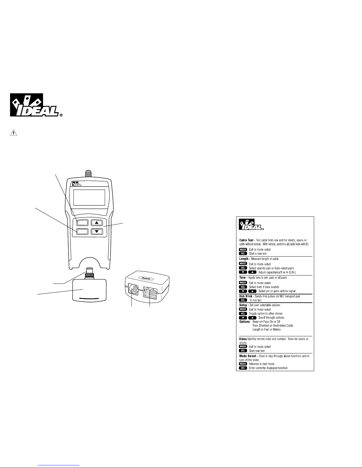
VDV Pro Key Functions
FEATURES
• Larger back-lighted LCD screen for better test results readability
• Toggle ON/OFF option of lighted display for battery power savings (Hold SEL for 2 seconds)
• Blinks HUBS to assure connected configurations
• Increased voice testing capability detects RJ-11 (1,2 and 3 pair)
• Voice test also shows Normal and Reserve for pins 1 through 6
• Length measurement is shown during initial test results for convenience and time savings
• Eight twisted pair remotes have both RJ-45 and RJ-11 jacks for longer life and increase testing capabilities
• Tone option for pins land 8 for cables connected to hub or switch
VDV PRO
Vo ice Data Video Cable Tester
1
Remote
SEL
MODE
REMOTE UNIT
Squeeze remote at finger grip
openings in main unit to
remove. Use same connector
on remote as on main unit.
Six modes of operation
• Cable Test • Tone
• Hub Blink • Coax
• Length • Setup Mode
Press SEL to:
• Turn on back
light (hold 2 sec)
• Execute current displayed mode
• Start new test cycle
• Select one of four tones
• Change pair being measured
for length
• Change user selectable options
- Beep On/Off
- Unshielded or Shielded Cable
- Units: Feet or Meters
- Split pair on/off
Arrow Keys
• To change length constant
(see chart for required parameters)
• To change pair or pin selection for
tone
• To scroll through setup selectable
options
COAX TEST TERMINATOR
VOICE DATA
REMOTE UNIT (Front view)
99 Washington Street
Melrose, MA 02176
Phone 781-665-1400
Toll Free 1-800-517-8431
Visit us at www.TestEquipmentDepot.com
Page 2

3
2
• Two line by 16 character full alphanumeric LCD with icons for clear results
• Tests for shield continuity, shorts, opens, miswires, reversals and split pairs with remote connected
• Cable Test – One ended testing for shorts, opens and split pairs (no remote connected)
• Test results displayed in wire map format with message line for shorts and split pairs
• Displays PASS and sounds beep (optional) for T568A/B
• Will display wiremap for 10Base-T and Token Ring with remote connected
• Length measurement in feet or meters using cable capacitance method
• UTP and STP length measurements with and without remote attached
• Coax mapping with up to eight coax remotes
• Tone generator mode sends four different tones on all conductors, selected pair or selected pin
• Auto-off in any mode and low power consumption for long battery life
• Low battery symbol indicates when to change battery
• Will identify if connected to network device during length test
• 9 volt battery included
VDV PRO Reference Card
Split pair on/off
DESCRIPTION
The VDV Pro can be powered on by pressing any of the four buttons. VDV Pro powers off automatically
after 20 minutes of continuous testing of a single cable. Disconnecting the cable restores the tester to
normal function. Most power-on modes will timeout in 20 minutes. The tone mode will power off after
21⁄2 hours. The VDV Pro will turn on in the last mode used before turning off. The back light is toggled
on and off by holding down SEL for 2 seconds or more. At power on, the back light is always on. The
back light turns off automatically 3 minutes after being turned on. (with or without test activity)
Upon completion of the test, the wire map, ID and any faults are displayed.
• The top line of numbers on the display represents the connector pins on the main unit.
• The second line of pin numbers is the connector pin numbers of the remote.
• If there is a miswire, the numbers on the second line will indicate the pin numbers detected.
• If no connection was detected for some of the pins, the second line will be blank in those pin locations.
• If a short is detected, the second line will have a flashing “ ”in that position, and the specific short
condition displayed on the third line.
• If a split pair is detected, the pins affected will flash on the second display line. The specific split
condition will be displayed on the third line.
• If there are multiple errors to display on the third line, the messages will be displayed in sequence
until all are displayed.
• Under “ID”, the number of the remote being used will be displayed.
There are five modes of operation as described below plus a setup function. In any mode, pressing the
MODE button causes the mode select screen to be displayed. The OFF message is usually the first one
displayed. Continued pressing of the MODE button will cycle through the other modes. Pressing the
SEL button causes the currently displayed mode to be entered.
Cable Test – If there is no remote, press any of the buttons to turn on the VDV Pro. The tester
will then test for shorts, opens, and split pairs. The results are displayed as messages on the LCD.
Whenever a new cable assembly is inserted for testing, press the SEL button to start a new test cycle.
Partial and erroneous results can occur if not done.
Length – The length mode measures the length of a cable by measuring its capacitance and using the
capacitance per unit of length (length constant) to calculate the length. The length is displayed on the LCD
along with the current value of the length constant. The SEL button changes the pair being measured in
a 1-2, 3-6, 4-5, 7-8 and auto-select sequence. The pair number is displayed next to the length except
in auto-select mode. If a selected pair has a fault, the fault replaces the length reading on the LCD. In
auto-select mode, the VDV Pro automatically selects a pair without a fault. Use the auto-select or 1-2 pair
settings to measure the length of a coax cable connected to the F-connector. The length
constant is changed with the up and down arrows. The CAL icon is on while adjusting the constant.
Note: If the far end of the cable is connected to a Network Device (Hub, Switch, etc.), the VDV Pro will
display “Network??”.
Typical Cable Parameters
Cable pF/ft pF/m
Data CAT3 19.0 62.5
CAT5/5E 15.0 49.0
CAT6 15.0 49.0
Coax RG6/U 16.25 53.0
RG11/U 16.25 53.0
RG58/U 27.5 90.0
RG59/U 16.25 53.0
Typical Cable Parameters
Cable pF/ft pF/m
Security Wire
22 AWG, Jacketed 24.0 78.5
22 AWG, Unjacketed 14.0 46.0
20 AWG, Unjacketed 16.0 52.5
18 AWG, Unjacketed 17.0 55.0
*
Page 3

5
Tone – The tone mode generates four different tones for use with tone tracers on all pairs, a selected
pair or a selected pin. The SEL button selects one of the four tone sounds provided. The up and
down arrows scroll through the pairs and pins that have signal on them. The VDV Pro has constant tone
amplitude over the life of the battery and two tone amplitude of normal and half (HI on pair and Low
on pin).
Note: When using the coax adapter or alligator clip assembly, tone is connected only to pin 1 and pin 2.
Video – The video mode is used in conjunction with special numbered and color-coded F-connector
terminators (coax remotes). These eight remotes each have unique signatures that the VDV Pro can
identify. The VDV Pro displays the remote number and color code if cable passes. If cable fails,
“Open” or “Short” will be displayed and coax mode.
Setup – The setup mode is provided to set user selectable options. The up and down arrow buttons
scroll through the options. The SEL button changes the current setting to the choice for that option.
To exit Setup, press Mode key.
• The beep-on-pass can be turned on or off (default is on).
• The pass criteria can be set for shielded or unshielded cables (default is unshielded).
• The length can be set for meters or feet (default is feet).
–If the length units are changed, the VDV Pro converts the currently set
length constant to the new units on exit of setup.
–The length constant can be set to any value (default is 15 pF/foot; most Cat 5, Cat 5e & Cat 6
are very close to 15pF/foot – check with your cable manufacturer for possible variances.)
Voltage Protection
The VDV Pro is designed to withstand input voltage conditions that occur during normal telephony
applications for a very short period of time (approximately 10 seconds). The VDV Pro monitors for
voltage presence in CABLE TEST, LENGTH or COAX modes. The “VOLTAGE!!” message appears on the
screen and the tone sounds continuously. Remove tester from line immediately or tester could be damaged. (see specs for specifics)
INSTRUCTIONS FOR USE
To Test a Patch Cable
1) Plug one end of patch cable into the RJ-45 jack on the tester.
2) Plug other end of cable into a remote unit or Remote jack on the tester.
3) Press any button to power on. Wiremap results will be displayed, as well as PASS if correctly
wired to T568 A/B standards. Beep tone also indicates a PASS. The test repeats every 5 seconds.
4) For FAIL, refer to Interpreting Cable Test Results at end of instruction guide. Neither PASS or
FAIL icon will show for open or Miswire. Inspect wiremap numbers for these types of errors.
5) Disconnect patch cable after test.
Note: Be sure Set-up mode is properly set for Unshielded versus Shielded cables (Unshielded
is default. If the internal Remote jack is used on the tester, the Remote ID will always show as 1.
To Test Cable from One Terminated End Only – Remote unit is not needed to run Cable Test.
1) Attach one end of supplied jumper cable to main jack on tester
and the other end to the wall plate or patch panel jack to be tested.
2) Turn on unit by pressing any button. If not in Cable Test mode,
press MODE until Cable Test is displayed, than press SEL button.
3) The tester will then test for shorts, opens, and split pairs.
The results are displayed as messages on the LCD.
4) Results should appear within 5 seconds. The test repeats every 5 seconds.
5) Disconnect cable after test.
6) Pressing SEL button starts a new test immediately when a new cable is inserted for testing.
Note: Jumper cables must be no more than 10% of the total run length or 3 feet, whichever is less.
4
To Test Installed Cable (Horizontal, in-wall cabling)
1) Attach remote(s) to far end of cabling with supplied jumper cable(s).
2) Attach the main unit to patch panel with supplied jumper cable.
3) Press any button to power on. Wiremap results and remote ID number will be displayed,
as well as PASS if correctly wired to T568 A/B standards. Beep tone also indicates a PASS.
The test repeats every 3 seconds.
4) When the RJ-11 adapter is used, the VDV Pro automatically senses and adjusts the pairing and pin
numbers to the 3-pair USOC standard in CABLE TEST, LENGTH, and TONE Generator modes. The
split pair testing is disabled.
5) In the RJ-45 mode, cross-over cables are recognized by displaying the PASS icon and adding
the “X-Over” message after length. In RJ-11 mode, reverse-pinned cables are recognized and a
“REV-PIN’D,” message added after length. The PASS icon is displayed if it is a correctly pinned
reverse-pinned position cable.
6) For FAIL, refer to Interpreting Cable Test Results at end of instruction guide. Neither PASS or
FAIL icon will show for open or Miswire. Inspect wiremap numbers for these types of errors.
7) Disconnect cable after test.
Note: Patch cables must be, no more than 10% of the total run length for accurate split pair indication.
To Measure Length
1) Connect cable to main unit. (A remote may or may not be present at other end.)
2) Turn on main unit by pressing any button. Cable length will be displayed whenever there are no
splits or shorts to report.
–To adjust pF “length constant” parameters, use arrow keys.
–To change pair measured, press SEL to cycle through pairs 1-2, 3-6, 4-5, 7-8.
(1-2 is default pair and must be used for coax length)
–To change length between feet and meters, use SETUP mode.
Note: Default is 15 pF/foot; most Cat 5, Cat 5e & Cat 6 are very close to 15pF/foot –
check with your cable manufacturer for possible variances.)
Note: If a selected pair has a fault, the fault replaces the length reading on the LCD. In default mode, if
the 1-2 pair has a fault, the VDV Pro automatically sequences to a pair without a fault.
Unknown Length Constant
If “length constant” is unknown for a particular cable, a known length of cable may be used to calibrate
the constant. Measure fifty feet of cable and attach main unit to one end. Turn on unit, press MODE
until LENGTH is displayed. Press up/down arrow keys until 50ft is displayed, then use the pF constant
displayed to measure length of unknown cable. (Fifty feet or more is suggested to minimize the
resolution error; 1 foot in 50 is 2% uncertainty).
To Test Coax
1) Attach cable to be tested to the F-connector on the adapter. Insert adapter into Main jack on
VDV Pro.
2) Attach coax remote terminator to wallplate on the other end.
3) Turn on main unit by pressing any button. If not in Video mode, press MODE until VIDEO is
displayed, than press SEL button.
4) Remote number and color will be displayed if cable passes. If cable fails, OPEN or SHORT will
be displayed.
5) Coax length may be measured by setting length constant to manufacturer’s specs and selecting pair
1-2 in LENGTH mode. (no remote required)
To Generate Tone
1) Turn on main unit by pressing any button. If not in tone mode, press MODE until TONE is
displayed, than press SEL button.
2) Press SEL until desired tone is selected. The up/down arrow keys select the pin or pair(s) to carry
the tone.
Page 4

7
3) Connect cable to be traced to main unit. For best signal, do not connect remote. Due to the
canceling effect of twisted pairs, the strongest signal is obtained by having one wire of a pair carry
tone. Selecting a single pin instead of a pair will do this.
4) To turn tone off, press the MODE button until OFF is displayed, then the SEL button. The tone will
power off automatically after 21⁄2 hours.
Note: When using the coax adapter or alligator clip assembly, tone is connected only to Pin 1 and Pin 2
To Blink Hub
When Mode is selected, the VDV Pro sends link pulses on the NIC transmit pair for 3 seconds, then
no pulse for 3 seconds for an overall cycle time of 6 seconds. The TEST icon is on when sending
pulses and off when not. It turns off automatically after 20 minutes.
BATTERY REPLACEMENT – When the “battery low” icon is on, the battery should be replaced as soon
as practical. The cable testing results will become unreliable when the battery reaches about 6.2 volts.
Note: When installing a new battery, disconnect any cables connected.
The length and cable test modes will be improperly calibrated if a cable is present.
SPECIFICATIONS
Environmental:
Operating temperature: 0 to 50°C (32 to 122°F)
Storage temperature: -10 to 60°C (14 to 140°F)
Humidity: 10% to 90%, non-condensing
Battery Life (9V Alkaline battery, typical) Times are for the full capacity
of the battery used continuously in one of the following modes:
Standby: 3.5 years
Cable Testing: No Back Light (Tone, Length, Test) 108 hours
(Hub Blink) 54 hours
Back Light On (Tone, Length, Test) 27 hours
(Hub Blink) 20 hours
Cable Types: Shielded or unshielded, Cat 6, Cat-5E, Cat-5, Cat-4, Cat-3 and Coax
Minimum cable length for testing for split pairs: 1 meter (3 feet)
Minimum cable length for TEST: 1.25 meter (4 feet)
Length measurement range (CAT5/6): 0 to 640 meters (0 to 2100 feet)
Length measurements coax cable: Average 3,000 ft. – depends on coax cable resistance values
Applied Voltage: 100 volts DC or RMS AC applied continuously. Can stand 240 volt peak.
INTERPRETING CABLE TEST RESULTS – The PASS icon will be on if the cable has all pins
properly connected per T568A/B standard. The FAIL icon will be on if there is a short or split pair.
Neither icon will be on if there are opens or miswires. The wiremap should be inspected for these
types of errors.
Definition of Errors – (See failure example drawings) The three classes of faults below are in order
of severity. The more severe wiremap error will mask less severe wiremap errors. For example, if
there is a short in the cable; miswires and splits pairs may not be detected until the short is corrected.
Short – The pair has a low resistance connection from one wire of any pair to another wire in any pair in
the cable or shield. A short with remote attached is indicated by the FAIL icon being on and flashing X’s in
the appropriate pin position of the second display line. Error messages listing all the pins shorted together
will also be displayed. In the CABLE TEST mode (no remote), all error messages will be displayed.
6
Miswire – Single or multiple conductors are not connected to the same pins at both ends of the cable.
With a remote attached, the wire map shows the pin numbers from display line 1 (main) to display line 2
(remote). A reverse pair is a special case of a miswire in which the pair is wired to the correct pair of pins, but
the two conductors are reversed. In CABLE TEST (no remote), this type of error is not detectable.
Split Pair – A split pair occurs when a cable is terminated consistently at both ends, but in the
wrong order. Twisted pair cables typically are made up of eight wires twisted together in 4 pairs.
These 4 pairs are designated as pairs by the wiring standards and are intended to carry a signal by
creating a circuit. 1 & 2, 3 & 6, 4 & 5 and 7 & 8 are the pairs designated by T568A/B for a RJ45
jack or plug. A cable can be wired with correct continuity but not with correct pairing. With remote
attached, the pin numbers split pairs flash and an error message is displayed listing the split pair
pin numbers. In the PRETEST mode (no remote), the Error message is displayed.
10BaseT Wiremap
(2 pair 4 wires)
Token Ring Wiremap
(2 pair 4 wires)
123 6
123 6
3456
3456
PASS DATA No Shield
12345678
12345678
ID 1
FAIL DATA Shield
12345678
12345678
Split 1236 ID 1
FAIL DATA Shield
12345678
13245678
Miswire 23 ID 1
FAIL DATA Shield
12345678
132456**
Short 78 ID 1
FAIL DATA Shield
12345678
345678
Open 1-2 ID 1
Examples of Wiring Errors (shielded)
OPEN
DARK = ON
LIGHT = FLASING
SHORT
MISWIRE
SPLIT PAIR
T568A/B Passing Cable (unshielded)
Page 5
• Opción de tonos para pines 1 y 8 para cables conectados al concentrador o switch.
• Pantalla LCD de dos líneas de 16 caracteres alfanuméricos completos con iconos para obtener
resultados claros
• Prueba si hay continuidad de blindaje, cortocircuitos, interrupciones, conexiones defectuosas,
inversiones y pares separados con unidad a distancia conectada
• Prueba de cable – Pruebas por un extremo de cortocircuitos, interrupciones y pares separados
(sin unidad a distancia conectada)
• Los resultados de las pruebas se muestran en un formato de diagrama de conexiones con línea de
mensajes para cortocircuitos y pares separados
• Muestra PASS (pasa) y emite un sonido (opcional) para T568A/B
• Mostrará un mapa de conexiones para 10Base-T y Token Ring (ficha circulante) con unidad a
distancia conectada
• Mide la longitud en pies o metros usando el método de capacitancia de cables
• Mide longitudes de cables de pares trenzados sin blindar, pares trenzados apantallados y coaxiales
con o sin unidad a distancia conectada
• Mediciones de longitud de cables de par retorcido sin blindar (UTP) y blindados (STP) con y sin
unidad remota conectada
• Mapeo de coaxiales con hasta ocho unidades coaxiales remotas
• Apagado automático en cualquier modalidad y bajo consumo de potencia para una larga duración
de la pila
• Símbolo de baja carga de la pila que indica cuándo se debe cambiar la misma
• Identificará si está conectado al dispositivo de la red durante la prueba de longitud
• Pila de 9 voltios incluida
9
Instrucciones del probador VDV Pro
¡Advertencia!
No lo conecte a cables con corriente. El VDV Pro puede dañarse.
¡Precaución!
Inspeccione los enchufes para ver si están bien terminados antes de introducirlos en el VDV Pro. La
longitud mínima del cable para probar si hay pares separados es de 3 pies.
Funciones de los botones del VDV Pro
CARACTERÍSTICAS
• Pantalla LCD iluminada y más grande para una mejor lectura de los resultados de las pruebas
• Opción de botón ON/OFF de pantalla iluminada para ahorro de energía de batería (presiones SEL
por 2 segundos)
• Parpadeo de HUBS para asegurar las configuraciones conectadas
• Capacidad mejorada de prueba de voz detecta RJ-11 (1, 2 y 3 pares)
• La prueba de voz también muestra Normal y Reversa para pines del 1 al 6
• La medición de longitud se muestra durante los resultados iniciales de la prueba para conveniencia
y ahorro de tiempo
• Ocho pares trenzados tienen jacks RJ-45 y RJ-11 para una mayor vida y mejores capacidades de
prueba.
8
VDV PRO
Voice Data Video Cable Tester
1
Remote
SEL
MODE
VOZ DATOS
UNIDAD REMOTA
(Vista anterior)
VDV PRO Reference Card
Split pair on/off
Seis modalidades de operación
• Prueba de cable
• Parpadeo de concentrador
• Longitud
• Tono
• Coaxial
• Modalidad de configuración
Teclas de flecha
• Para cambiar la constante de
longitud (vea los parámetros
necesarios en la tabla)
• Para cambiar el par o la clavija
seleccionada para el tono
• Para recorrer las opciones
seleccionables de configuración
Pulse SEL para:
• Encienda la luz
posterior (presione por
2 segundos)
• Ejecutar la modalidad en curso
mostrada
• Empezar el nuevo ciclo de prueba
• Seleccionar uno de cuatro tonos
• Ambiar el par cuya longitud vaya a
medirse
• Cambiar las opciones seleccionables
por el usuario
–Pitido activado/desactivado
–Cable sin proteger o protegido
–Unidades – Pies o metros
–Pares separados activado/desactivado
UNIDAD REMOTA
Para retirar la unidad remota, apriétela en las
aberturas para los dedos de la unidad principal. Use
en la unidad remota el mismo conector que en la unidad principal.
TERMINADOR PARA PRUEBA
DE COAXIALES
Page 6

11
DESCRIPCIÓN
El VDV Pro puede encenderse presionando cualquiera de los cuatro botones. VDV Pro se apaga
automáticamente tras 20 minutos de pruebas continuas de un solo cable. Al desconectar el cable,
se restablece el probador a la función normal. La mayoría de las modalidades de encendido desaparecerá en 20 minutos. La modalidad de tono se apagará después de 21⁄2 horas. El VDV Pro se
encenderá en la última modalidad usada antes de apagarlo. La luz posterior se enciende y apaga presionando SEL por 2 segundos o más. En el poder en, la luz de atrás es siempre en. La luz posterior se
apaga automáticamente 3 minutos después de haber sido encendida (con o sin actividad de prueba).
Después de terminar la prueba, se mostrará el diagrama de conexiones, la identificación y las fallas,
de haberlas.
• La línea superior de números de la pantalla representa las clavijas de los conectores en la unidad
principal.
• La segunda línea de números de clavija son los números de clavija de la unidad a distancia.
• Si hay una conexión defectuosa, los números de la segunda línea indicarán los números de clavija
detectados.
• Si no se detecta ninguna conexión para algunas de las clavijas, la segunda línea estará en blanco
en las posiciones de esas clavijas.
• Si se detecta un cortocircuito, la segunda línea tendrá una “ “ intermitente en esa posición, y la
condición de cortocircuito específica se mostrará en la tercera línea.
• Si se detecta un par separado, las clavijas afectadas destellarán en la segunda línea mostrada. La
condición de separación específica se mostrará en la tercera línea.
• Si hay que mostrar múltiples errores en la tercera línea, los mensajes se mostrarán en orden hasta
que se muestren todos.
• Debajo de “ID”, se mostrará el número de unidad a distancia que se está usando.
Hay cinco modalidades de operación según se describe abajo más una función de configuración. En
cualquier modalidad, la pulsación del botón MODE hace que se muestre la pantalla de selección de
modalidad. El mensaje OFF es normalmente el primero que se muestra. La pulsación continuada del
botón MODE permitirá recorrer las otras modalidades. La pulsación del botón SEL permite introducir
la modalidad mostrada en ese momento.
Prueba de cable – Si no hay unidad a distancia, pulse cualquiera de los botones para encender el
VDV Pro. A continuación probará si hay cortocircuitos, interrupciones y pares separados. Los resultados se muestran en forma de mensajes en la pantalla LCD. Siempre que se introduzca un nuevo
conjunto de cable para probar, pulse el botón SEL para empezar un nuevo ciclo de prueba. Se pueden
producir resultados parciales y erróneos si no se hace.
Longitud – La modalidad de longitud mide la longitud de un cable midiendo su capacitancia y usando
la capacitancia por unidad de longitud (constante de longitud) para calcular la longitud. La longitud
se muestra en la pantalla LCD junto con el valor actual de la constante de longitud. El botón SEL cambia
el par que se mide en una secuencia 1-2, 3-6, 4-5, 7-8 y selección automática. El número de par se
muestra junto a la longitud excepto en la modalidad de selección automática. Si un par seleccionado
tiene una falla, la falla reemplaza la lectura de longitud en la pantalla LCD. En la modalidad de selección
automática, el VDV Pro selecciona automáticamente un par sin una falla. Use la selección automática
o los ajustes del par 1-2 para medir la longitud de un cable coaxial conectado al conector F. La constante de longitud se cambia con las flechas arriba y abajo. El icono CAL está encendido mientras se
ajusta la constante.
Nota: Si el extremo alejado del cable está conectado a un dispositivo de red (borne de tablero
de conexiones, interruptor, etc.), el VDV Pro mostrará “Network??”.
Tono – La modalidad de tono genera cuatro tonos diferentes para usar con rastreadores de tonos en
todos los pares, un par seleccionado o una clavija seleccionada. El botón SEL permite seleccionar
uno de los cuatro tonos proporcionados. Las flechas arriba y abajo recorren los pares y clavijas que
tienen una señal. El VDV Pro tiene una amplitud de tono constante durante la vida útil de la pila y una
amplitud de dos tonos de normal y medio (ALTO en par y BAJO en clavija).
10
Parámetros típicos del cable
Cable pF/pie pF/mt
Datos CAT3 19.0 62.5
CAT5/5E 15.0 49.0
CAT6 15.0 49.0
Coaxial RG6/U 16.25 53.0
RG11/U 16.25 53.0
RG58/U 27.5 90.0
RG59/U 16.25 53.0
Parámetros típicos del cable
Cable pF/pie pF/mt
Cable de seguridad
22 AWG, Cubierto 24.0 78.5
22 AWG, Decubierto 14.0 46.0
20 AWG, Decubierto 16.0 52.5
18 AWG, Decubierto 17.0 55.0
Nota: Al usar el adaptador coaxial o conjunto de pinzas de caiman, el tono se conecta sólo a la clavija
1 y clavija 2.
Video – El modo de video se usa junto con terminadores de conectores F especiales numerados y de
colores (unidades coaxiales remotas) Estas ocho unidades remotas disponen de identificaciones exclusivas que el VDV Pro puede detectar. El VDV Pro muestra el número y el código de color de la unidad
remota si el cable pasa la prueba. Si el cable falla, se muestra “Open” (Abierto) o “Short” (En corto) en
modo de prueba de coaxiales.
Configuración – La modalidad de configuración se proporciona para fijar opciones seleccionables
por los usuarios. Los botones de flecha arriba y abajo recorren las opciones. El botón SEL cambia el
ajuste actual a la preferencia para esa opción. Para salir de Configuración, pulse el botón Mode.
• El pitido al pasar puede activarse o desactivarse (la opción implícita es activado).
• Se pueden fijar los criterios para cables protegidos o sin proteger (la opción implícita es sin proteger).
• La longitud puede fijarse en metros o pies (la opción implícita es pies).
–Si se cambian las unidades de longitud, el VDV Pro convierte la constante de longi tud mostrada
en ese momento en las nuevas unidades al salir de la configuración.
–La constante de longitud puede fijarse en cualquier valor (la opción implícita es 15 pF/pie; la
mayoría de los Cat 5, Cat 5e y Cat 6 se aproximan mucho a 15pF/pie – compruebe las posibles
variaciones con el fabricante de cables).
Protección de voltaje
El VDV Pro está diseñado para resistir condiciones de voltaje de entrada que se producen durante las
aplicaciones de telefonía normales durante un período muy corto (aproximadamente 10 segundos).
El VDV Pro supervisa la presencia de voltaje en las modalidades PRUEBA DE CABLE, LONGITUD
o COAXIAL. Aparece el mensaje “VOLTAGE!!” (¡voltaje!) en la pantalla y el tono suena de forma
continua. Quite el probador de la línea inmediatamente, ya que lo contrario se puede dañar (vea las
especificaciones para una explicación más específica)
INSTRUCCIONES DE EMPLEO
Para probar un cable de conmutación
1) Enchufe un extremo del cable de interconexión temporal en el jack RJ-45 del instrumento.
2) Enchufe el otro extremo del cable en una unidad a distancia o jack a distancia del probador.
3) Presione cualquier botón para encenderlo. Se mostrarán los resultados de los esquemas de
conexiones, así como PASS (pasa) si están bien conectados según las normas T568 A/B. El tono
también indica un PASS (pasa). La prueba se repite cada 5 segundos.
4) En caso de FAIL (falla), consulte Cómo interpretar los resultados de las pruebas de los cables al
final de la guía de instrucciones. No se mostrará ningún icono PASS o FAIL para interrupción o
conexión deficiente. Inspeccione los números del esquema de conexiones en lo que se refiere a
estos tipos de errores.
5) Desconecte el cable de conmutación después de la prueba.
Nota: Asegúrese de que la modalidad de configuración esté bien fijada para cables sin blindar en
comparación con cables blindados (sin blindar es la opción implícita. Si se usa el jack a distancia en
el probador, el ID a distancia se mostrará siempre como un 1.
Para probar el cable por un extremo terminado solamente – No se necesita la unidad a
distancia para ejecutar la Prueba de Cable.
*
Page 7

13
1) Conecte un extremo del cable puente suministrado al jack principal del probador y el otro extremo
a un enchufe de la pared o jack del panel de conmutación que se vaya a probar.
2) Encienda la unidad pulsando cualquier botón. Si no está en la modalidad de prueba de cable,
pulse MODE hasta que se muestre PRETEST (prueba de cable), después pulse el botón SEL.
3) El probador buscará cortocircuitos, interrupciones y pares separados. Los resultados se muestran
en forma de mensajes en la pantalla LCD.
4) Los resultados deben aparecer en un plazo de 3 segundos. La prueba se repite cada 5 segundos.
5) Desconecte el cable después de la prueba.
6) La pulsación del botón SEL da comienzo una nueva prueba inmediatamente cuando se inserta
un cable nuevo para pruebas.
Nota: Los cables puente no deben tener más del 10% de la longitud total del tramo o 3 pies,
el que sea menor.
Para probar un cable instalado (cable horizontal en la pared)
1) Conecte las unidades a distancia al extremo más alejado del cable con los cables puente
suministrados.
2) Conecte la unidad principal al tablero de conmutación con el cable puente suministrado.
3) Presione cualquier botón para encenderlo. Se mostrarán los resultados del diagrama de conexiones y número de ID a distancia, así como PASS si están bien conectados según las normas T568
A/B. El tono también indica PASS. La prueba se repite cada 5 segundos.
4) Cuando se usa el adaptador RJ-11, el VDV Pro sensa y ajusta automáticamente los pares y números de pines al estándar de 3 pares USOC en las modalidades PRUEBA DE CABLE, LONGITUD y
GENERADOR DE TONO. La prueba de pares separados se deshabilita.
5) En la modalidad RJ-45, los cables cruzados se reconocen al mostrar el icono PASS y agregar
el mensaje X-over luego de la longitud. El icono PASS se muestra si es un cable de 6 posiciones
con los pines en reversa correctamente colocados.
6) Para FAIL, consulte Cómo interpretar los resultados de las pruebas de los cables al final de la guía
de instrucciones. Ni el icono PASS o FAIL se mostrarán para interrupción o conexión deficiente.
Inspeccione los números del diagrama de conexiones para estos tipos de errores.
5) Desconecte el cable después de la prueba.
Nota: Los cables de conmutación no deben ser más del 10% del tramo total para lograr una
indicación exacta del par separado.
Para medir la longitud
1) Conecte el cable a la unidad principal. (Es posible que haya o no haya una unidad a distancia
en el otro extremo).
2) Encienda la unidad principal pulsando cualquier botón. La longitud del cable se mostrará siempre
que no haya separaciones o cortos que reportar.
–Para ajustar los parámetros pF de “longitud constante”, use las teclas de flecha.
–Para cambiar el par medido, pulse SEL para ciclar por los pares 1-2, 3-6, 4-5, 7-8.
(1-2 es el par implícito y debe usarse para la longitud coaxial)
–Para cambiar la longitud entre pies y metros, use la modalidad de CONFIGURACIÓN.
Nota: El valor implícito es 15 pF/pie; la mayoría de los Cat 5, Cat 5e y Cat 6 se aproximan mucho a
15pF/pie – compruebe con su fabricante de cables en lo que se refiere a las posibles variaciones).
Nota: Si un par seleccionado tiene una falla, la falla reemplaza la lectura de longitud en la pantalla
LCD. En la modalidad implícita, si el par 1-2 tiene una falla, el VDV Pro secuencia automáticamente a
un par sin una falla.
12
Constante de longitud desconocida
Si la “constante de longitud” es desconocida para un cierto cable, se puede usar una longitud conocida
de cable para calibrar la constante. Mida cincuenta pies de cable y conecte la unidad principal a un
extremo. Encienda la unidad, pulse MODE hasta que se muestre LENGTH. Pulse las teclas de flecha
arriba/abajo hasta que se muestre 50 pies, después use la constante pF mostrada para medir la longitud
del cable desconocido. (Se recomienda cincuenta pies o más para disminuir al mínimo el error de
resolución; 1 pie en 50 representa una incertidumbre del 2%).
Para probar cables coaxiales
1) Conecte el cable que se vaya a probar al conector F del adaptador. Introduzca el adaptador en el
jack principal del VDV Pro.
2) Conecte el terminador de la unidad a distancia coaxial al enchufe de la pared en el otro extremo.
3) Encienda la unidad principal pulsando cualquier botón. Si no está en modo de video, pulse MODE
hasta que aparezca VIDEO y luego pulse el botón SEL.
4) Se mostrarán el número y color de la unidad a distancia si el cable pasa. Si el cable falla, se
mostrará OPEN (interrupción) o SHORT (cortocircuito).
5) La longitud del cable coaxial puede medirse fijando la constante de la longitud según las especificaciones del fabricante y seleccionando un par 1-2 en la modalidad de LONGITUD. (no se necesita
una unidad a distancia)
Para generar un tono
1) Encienda la unidad principal pulsando cualquier botón. Si no está en la modalidad de tono, pulse
MODE hasta que se muestre TONE, después pulse el botón SEL.
2) Pulse SEL hasta seleccionar el tono deseado. Las teclas de flecha arriba/abajo seleccionan la
clavija o pares para transportar el tono.
3) Conecte a la unidad principal el cable que se vaya a identificar. Para obtener la mejor señal, no
conecte la unidad a distancia. Debido al efecto de cancelación de los pares retorcidos, la señal
más fuerte se obtiene haciendo que un cable de un par transporte el tono. La selección de una
sola clavija en vez de un par permitirá hacer esto.
4) Para desconectar el tono, pulse el botón MODE hasta que aparezca OFF, después selecciona
el botón SEL. El tono se desconectará automáticamente después de 2 1⁄2 horas.
Nota: Al usar el adaptador coaxial o conjunto de pinzas de caiman, el tono estará conectado sólo
a la clavija 1 y clavija 2
Para parpadear el concentrador
Cuando se selecciona Mode, el VDV Pro envía pulsos de enlace al par de transmisión NIC por 3
segundos, luego ningún pulso por 3 segundos para un tiempo de ciclo completo de 6 segundos. El
icono TEST se enciende cuando se envía los pulsos y se apaga cuando no se envían.
Se apaga automáticamente luego de 20 minutos.
REEMPLAZO DE LA PILA – Cuando aparezca el icono de “pila baja”, se debe reemplazar la pila
tan pronto como sea posible. Los resultados de las pruebas de cables dejarán de ser fiables cuando
la pila llegue a unos 6,2 voltios.
Nota: Al instalar la pila nueva, desconecte cualquier cable conectado. Las modalidades de longitud
y prueba de cable se calibrarán de la forma indebida si un cable está presente.
Page 8

15
ESPECIFICACIONES
Medioambientales:
Temperatura de operación: 0 a 50°C (32 a 122°F)
Temperatura de almacenamiento: -10 a 60°C (14 a 140°F)
Humedad: 10% a 90%, incondensables
Duración de la pila (pila alcalina típica de 9V). Los tiempos son para la capacidad máxima
de la pila usada continuamente en una de las modalidades siguientes Reserva: 3,5 años
Pruebas de cables: sin luz posterior (tono, longitud, prueba) 108 horas.
(parpadeo de concentrador) 54 horas
Luz posterior encendida (tono, longitud, prueba) 27 horas
(parpadeo de concentrador) 20 horas
Tipos de cables: Blindados o sin blindar, Cat 6, Cat-5E, Cat-5, Cat-4, Cat-3 y coaxial
Longitud mínima del cable para probar pares separados: 1 metro (3 pies)
Longitud mínima del cable para PRUEBA: 1,25 metros (4 pies)
Intervalo de medidas de longitud (CAT5/6): 0 a 640 metros (0 a 2100 pies)
Medidas de longitud de cables coaxiales: - Promedio 3.000 pies -
depende de los valores de resistencia del cable coaxial
Voltaje aplicado: 110 voltios DC o AC RMS aplicados en forma contínua. Puede soportar 240 voltios
pico.
CÓMO INTERPRETAR LOS RESULTADOS DE LAS PRUEBAS DE CABLES – El icono PASS
(pasa) estará encendido si el cable tiene todas las clavijas bien conectadas según la norma T568A/B.
El icono FAIL (falla) estará encendido si se produce un cortocircuito o un par separado. No se encenderá
ningún icono si hay cortocircuitos o conexiones defectuosas. Se debe inspeccionar el diagramas de
conexiones para estos tipos de errores.
Definición de errores – (Vea los dibujos de los ejemplos de fallas) Las tres clases de fallas
siguientes están ordenadas por orden de gravedad. El error más grave del diagrama de conexiones
ocultará otros errores menos graves del diagrama de conexiones. Por ejemplo, si hay un cortocircuito
en el cable; es posible que no se detecten las conexiones defectuosas y los pares separados hasta
que se corrija el cortocircuito.
Cortocircuito – El par tiene una baja conexión de resistencia de un cable de cualquier par a otro
cable de cualquier par en el cable o blindaje. Un cortocircuito con una unidad a distancia conecta
viene indicado por el icono FAIL encendido y unas X intermitentes en la posición apropiada de las
clavijas de la segunda línea de la pantalla. También se mostrarán los mensajes de error indicando
todas las clavijas cortocircuitadas juntas. En la modalidad de PRUEBA DE CABLE (sin unidad a
distancia), se mostrarán todos los mensajes de error.
Conexión defectuosa – Un solo conductor o múltiples conductores no están conectados a las
mismas clavijas en ambos extremos del cable. Con una unidad a distancia conectada, el diagramas
de conexiones muestra los números de clavija de la línea 1 de la pantalla (principal) a la línea 2 de la
pantalla (a distancia). Una inversión de par es un caso especial de conexión defectuosa en el que el
par está conectado al par correcto de clavijas, pero los dos conductores están invertidos. En PRUEBA
DE CABLE (sin unidad a distancia), no se puede detectar este tipo de error.
14
Par separado – Se produce un par separado cuando un cable está terminado uniformemente en ambos
extremos, pero en orden equivocado. Los cables de par retorcido están formados típicamente por ocho
cables retorcidos juntos en 4 pares. Estos 4 pares están diseñados como pares por las normas de conexiones y tienen como finalidad transportar una señal creando un circuito. 1 y 2, 3 y 6, 4 y 5 y 7 y 8 son los
pares designados por T568A/B para un jack o enchufe RJ45. Se puede conectar un cable de continuidad
correcta pero no sin los pares correctos. Con la unidad a distancia, destellan los números de clavija de
los pares separados y se muestra un mensaje de error indicando los números de clavija de pares separados. En la modalidad PRUEBA DE CABLE (sin unidad a distancia), se muestra el mensaje de error.
10BaseT Wiremap
(2 pair 4 wires)
Token Ring Wiremap
(2 pair 4 wires)
123 6
123 6
3456
3456
PASS DATA No Shield
12345678
12345678
ID 1
FAIL DATA Shield
12345678
12345678
Split 1236 ID 1
FAIL DATA Shield
12345678
13245678
Miswire 23 ID 1
FAIL DATA Shield
12345678
132456**
Short 78 ID 1
FAIL DATA Shield
12345678
345678
Open 1-2 ID 1
Examples of Wiring Errors (shielded)
OPEN
DARK = ON
LIGHT = FLASING
SHORT
MISWIRE
SPLIT PAIR
T568A/B Passing Cable (unshielded)
Page 9

CARACTÉRISTIQUES
• Afficheur à cristaux liquides rétroéclairé pour une meilleure lisibilité des résultats
• Option de basculement (allumé/éteint) du rétroéclairage de l’afficheur pour économiser
la pile (appuyer sur SEL pendant 2 secondes)
• Fait clignoter les concentrateurs pour assurer des configurations connectées
• Capacité accrue d’essai vocal détecte les connecteurs RJ-11 (1, 2 et 3 paires)
• L’essai vocal indique aussi Normal et Inversé pour les broches de 1 à 6
• La mesure de longueur est indiquée lors des résultats d’essai initiaux par commodité et pour gagner
du temps
• Huit téléconnexions à paires torsadées ont des fiches RJ-45 et RJ-11 pour une plus grande longévité et une amélioration des capacités d’essai
Notice d’utilisation de l’appareil de contrôle VDV Pro
Important :
Ne jamais relier à des câbles sous tension, sous peine d’endommager le VDV PRO.
Attention!
Vérifier que les fiches sont pourvues du bon connecteur avant de les introduire dans le VDV PRO.
Pour tester l’état d’une paire séparée, la longueur minimale de câble est de 3 pieds.
Fonctions essentielles du VDV PRO
17
• Option de tonalité pour les broches 1 et 9 des câbles connectés à un concentrateur ou un interrupteur
• Afficheur à cristaux liquides sur deux lignes de 16 caractères alphanumériques avec icônes pour
la clarté des résultats
• Essais de continuité de blindage, courts-circuits, circuits ouverts, mauvais raccordements,
inversions et paires séparées avec téléconnexion
• Essai préliminaire – Essai unilatéral sur courts-circuits, circuits ouverts et paires séparées
(sans téléconnexion)
• Les résultats d’essais s’affichent sous forme de plan de câblage avec une ligne de message pour les
courts-circuits et les paires séparées
• Affiche PASS et émet un bip (optionnel) pour le T568A/B
• Affiche un plan de câblage pour 10Base-T et anneau à jeton avec téléconnexion
• Mesure de longueur en pieds ou en mètres, au moyen de la méthode de capacité du câble
• Mesures de longueur de paires torsadées non blindées et de câbles à paires torsadées écrantées
avec ou sans téléconnexion
• Mappage coaxial avec jusqu’à huit téléconnexions
• Le mode générateur de tonalité envoie quatre tonalités différentes sur tous les conducteurs,
sur une paire sélectionnée ou une broche sélectionnée
• Arrêt automatique sous tous les modes et consommation réduite pour une autonomie plus longue
• Le symbole Low battery (pile faible) indique quand la pile doit être changée
• Identifie s’il est connecté au dispositif de réseau pendant l’essai de longueur
• Pile 9 volts incluse
VDV PRO Reference Card
Split pair on/off
VDV PRO
Voice Data Video Cable Tester
1
Remote
SEL
MODE
TELEPHONE DONNÉES
UNITÉ DE TÉLÉCONNEXION
(Vue de devant)
Appuyer sur SEL pour effectuer
les opérations suivantes:
• Allumer le rétroéclairage
(appuyer 2 secondes)
• Exécuter le mode en cours affiché
• Démarrer un nouveau cycle d’essai
• Sélectionner l’une des quatre tonalités
• Changer de paire dans le cadre d’une
mesure de longueur
• Modifier les options sélectionnables
par l’utilisateur
–Activer/désactiver le bip
–Câble blindé ou non blindé
–Unités – pieds ou mètres
–Paires sépareés Activer/désactiver
Touches fléchées
• Modifier la constante de
longueur (voir paramètres
requis dans le tableau)
• Modifier le choix de paire ou
de broche pour la tonalité
• Dérouler les options de
configuration sélectionnables
par l’utilisateur
Quatre modes de fonctionnement
• Cable Test (essai de c
âble)
• Hub Link (Liaison de
concentrateur)
• Length (longueur)
• Tone (tonalité)
• Coax (coaxial)
• Setup Mode (Mode configuration)
16
TERMINATEUR DE TEST COAXIAL
UNITÉ DE TÉLÉCONNEXION
Pincer l’unité de téléconnexion aux
ouvertures de doigts de l’unité principale
pour la retirer. Utiliser le même connecteur
sur l’unité de téléconnexion que sur l’unité principale
Page 10

Remarque: Si l’extrémité éloignée du câble est raccordée à un appareil Network (Hub, Switch, etc.) le
VDV Pro affiche « Network ?? ».
Tone (tonalité) – Le mode tonalité génère quatre tonalités différentes à utiliser avec un échomètre
sur toutes les paires, sur une paire sélectionnée ou sur une broche sélectionnée. Le bouton SEL permet
de sélectionner l’une des quatre tonalités proposées. Les flèches vers le haut et vers le bas permettent
de faire défiler les paires et les broches auxquelles un signal est appliqué. Le VDV Pro offre une ampli-
tude de tonalité constante pendant la durée de vie de la pile et deux amplitudes de tonalité normale et
demi-tonalité (HI – élevée sur paire et Low – faible sur broche).
Remarque: Lors de l’utilisation de l’adaptateur coaxial ou de l’ensemble à pince crocodile,
la tonalité n’est appliquée qu’aux broches 1 et 2.
Vidéo – Le mode vidéo s’utilise conjointement avec des terminateurs de connecteur F chromocodés
et à numérotation spécifique (téléconnexions coaxiales). Ces huit téléconnexions sont dotées chacune
d’une signature propre que le VDV Pro peut identifier. Le VDV Pro affiche le code de couleur et le
numéro de la téléconnexion si le câble subit l’essai avec succès. Dans le cas contraire, « Open » (circuit ouvert ) ou « Short » (court-circuit) s’affichent sous le mode coaxial.
Setup (configuration) – Le mode configuration permet de définir les options sélectionnables par
l’utilisateur. Les flèches vers le haut et vers le bas servent à faire défiler les options. Le bouton SEL
remplace le paramètre actuel par le choix d’option. Pour quitter le mode Setup, appuyer sur la touche
Mode.
• Le bip d’essai satisfaisant peut être activé ou désactivé (il est activé par défaut).
• Les critères de succès peuvent se définir pour les câbles blindés et les câbles non blindés (câbles
non blindés par défaut).
• La longueur peut se définir en mètres ou en pieds (en pieds par défaut).
–En cas de modification des unités de longueur, le VDV Pro convertit la constante de longueur
actuelle selon la nouvelle unité dès que la sortie du mode Setup (configuration).
–La constante de longueur peut être définie à une valeur quelconque (la valeur par défaut étant
15 pF/pi ; la plupart des Cat 5, Act 5e et Cat 6 sont très proches de 15 pF/pi – consulter le
fabricant de câbles concernant les éventuels écarts).
Protection contre la surtension
Le VDV Pro est conçu pour résister à des tensions d’entrée survenant dans des applications de téléphonie normales sur une période très courte (environ 10 secondes). Le VDV Pro contrôle la présence de
tension sous les modes CABLE TEST (essai de câble), LENGTH (longueur) ou COAX (coaxial). Le
message “VOLTAGE!!” (tension !!) s’affiche et une tonalité est émise de façon continue. Débrancher
immédiatement l’appareil de contrôle de la ligne électrique, car il pourrait être endommagé. (Consulter
les Spécifications pour de plus amples détails)
MODE D’EMPLOI
Pour contrôler un cordon de connexion
1) Brancher une extrémité du cordon de raccordement dans la prise de jack RJ-45 de l’appareil de
contrôle.
2) Brancher l’autre extrémité du câble sur un appareil à distance ou sur la prise de jack de
téléconnexion de l’appareil de contrôle.
3) Appuyer sur n’importe quel bouton pour activer. Les résultats du plan de câblage s’affichent ainsi
que le message PASS (succès) en cas de connexion conforme aux normes T568 A/B. Un bip est
également émis pour indiquer que l’essai s’est déroulé avec succès. L’essai est renouvelé toutes
les 5 secondes.
4) En cas de message FAIL (échec), se reporter à l’Interprétation des résultats d’essais sur câbles, à la fin
de la notice d’utilisation. En cas de mauvais raccordement ou de circuit ouvert, l’appareil n’affiche ni
l’icône PASS ni l’icône FAIL. Pour ce type d’erreurs, vérifier les numéros du plan de câblage.
5) Après l’essai, débrancher le cordon de connexion.
19
DESCRIPTIF
Il suffit d’appuyer sur l’un quelconque des quatre boutons pour activer le VDV Pro. Le VDV Pro se
désactive automatiquement au bout de 20 minutes d’essai continu sur un seul câble. Le débranchement du câble remet l’appareil sous son fonctionnement normal. La plupart des modes sous tension
se désactivent au bout d’un intervalle de 20 minutes. Le mode “Tone” (tonalité) est mis hors fonction
au bout de 2 heures 30 minutes. Le VDV Pro se met sous tension sous le dernier mode utilisé avant la
mise hors tension. On allume et on éteint le rétroéclairage en appuyant pendant 2 secondes ou plus
sur SEL. Au pouvoir sur, l’arrière allumer est toujours sur. Le rétroéclairage s’éteint automatiquement
3 minutes après son allumage (qu’il y ait ou non essai).
• La ligne supérieure de numéros de l’afficheur représente les broches du connecteur de l’unité principale.
• La deuxième ligne de numéros de broches correspond aux broches de la téléconnexion.
• En cas de mauvais raccordement, les numéros de la deuxième ligne indiquent les broches détectées.
• Si aucune connexion n’est détectée pour certaines broches, ces emplacements de broches restent
vierges sur la deuxième ligne.
• En cas de détection de court-circuit, un « » clignote sur la position correspondante et l’état
spécifique de court-circuit s’affiche sur la troisième ligne.
• En cas de détection de paire séparée, les broches concernées clignotent sur la deuxième ligne de
l’afficheur. L’état spécifique de séparation s’affiche sur la troisième ligne.
• En cas de nécessité d’affichage d’erreurs multiples sur la troisième ligne, les messages apparaissent
les uns à la suite des autres jusqu’à l’affichage de l’intégralité des messages.
• Sous “ID”, le numéro de la téléconnexion en cours d’utilisation s’affiche.
Ainsi que décrit ci-dessous, il existe quatre modes de fonctionnement et une fonction de configuration.
Sous tous ces modes, le fait d’appuyer sur le bouton MODE provoque l’affichage de l’écran de sélection
de mode. D’une manière générale, le message “OFF” (désactivé) s’affiche en premier. Une pression
continue sur le bouton MODE permet de faire défiler les autres modes. Une pression sur le bouton
SEL permet d’entrer le mode actuellement affiché.
Cable test (essai de câble) – En l’absence de téléconnexion, appuyer sur l’un quelconque des
boutons pour mettre le VDV Pro sous tension. L’appareil contrôle dès lors les courts-circuits, les circuits ouverts et les paires séparées. Les résultats s’affichent sous forme de messages sur l’afficheur à
cristaux liquides. A chaque fois qu’un nouveau câble est introduit pour être soumis à l’essai, appuyer
sur le bouton SEL pour démarrer un nouveau cycle d’essai. A défaut, des résultats erronés ou partiels
peuvent se produire.
Length (longueur) – Le mode longueur permet de mesurer la longueur d’un câble en en mesurant
la capacité et en utilisant la capacité par unité de longueur (constante de longueur) pour calculer la
longueur. La longueur s’affiche sur l’afficheur à cristaux liquides, avec la valeur actuelle de la constante de longueur. Le bouton SEL transforme la paire mesurée en une suite de numéros de paires
1-2, 3-6, 4-5, 7-8 et sélection automatique. Le numéro de paire s’affiche en regard de la longueur,
excepté sous le mode de sélection automatique. En cas de défaut détecté sur une paire sélectionnée,
le défaut remplace la mesure de longueur sur l’afficheur à cristaux liquides. Sous le mode de sélection automatique, le VDV Pro sélectionne automatique une paire dépourvue de défauts. Utiliser les
paramètres de sélection automatique ou de la paire 1-2 pour mesurer la longueur d’un câble coaxial
raccordé au connecteur F. Pour modifier la constante de longueur, utiliser les flèches vers le haut et
vers le bas. L’icône CAL (étalonnage) est active durant le réglage de constante.
18
Paramètres caractéristiques de câbles
Câble pF/pi pF/m
Données CAT3 19.0 62.5
CAT5/5E 15.0 49.0
CAT6 15.0 49.0
Coaxial RG6/U 16.25 53.0
RG11/U 16.25 53.0
RG58/U 27.5 90.0
RG59/U 16.25 53.0
Paramètres caractéristiques de câbles
Câble pF/pi pF/m
Fil de sécurité
22 AWG, Gainé 24.0 78.5
22 AWG, Sans gaine 14.0 46.0
20 AWG, Sans gaine 16.0 52.5
18 AWG, Sans gaine 17.0 55.0
*
Page 11

Remarque: En cas de défaut détecté sur une paire sélectionnée, le défaut remplace la mesure de longueur sur l’afficheur à cristaux liquides. Sous le mode par défaut, si la paire 1-2 présente un défaut, le
VDV Pro passe automatiquement à une paire sans défaut.
Constante de longueur inconnue
Si la constante de longueur est inconnue pour un câble donné, une longueur connue de câble peut servir
à étalonner la constante. Mesurer cinquante pieds de câble et raccorder l’unité principale à une extrémité.
Mettre l’appareil sous tension, appuyer sur MODE jusqu’à l’affichage de LENGTH (longueur). Appuyer
sur les touches fléchées vers le haut et vers le bas jusqu’à l’affichage de 50 pieds, puis utiliser la constante affichée en pF pour mesurer la longueur inconnue de câble. (la valeur de 50 pieds est suggérée
pour minimiser l’erreur de résolution ; un pied sur 50 correspond à 2 % d’incertitude).
Pour contrôler un câble coaxial
1) Raccorder le câble à tester au connecteur F sur l’adaptateur. Introduire l’adaptateur dans
la prise de jack principale du VDV Pro.
2) Raccorder le terminateur de la téléconnexion coaxiale à la plaque murale de l’autre extrémité.
3) Appuyer sur un bouton quelconque pour mettre l’unité principale sous tension. Si l’appareil n’est
pas sous le mode Vidéo, appuyer sur MODE jusqu’à l’affichage du mode VIDÉO puis appuyer sur le
bouton SEL.
4) Si le câble subit l’essai avec succès, le numéro et la couleur de la téléconnexion s’affichent.
En cas d’échec, OPEN (circuit ouvert) ou SHORT (court-circuit) s’affichent.
5) Il est possible de mesurer la longueur du câble coaxial en définissant la constante de longueur
conformément aux spécifications du fabricant et en sélectionnant la paire 1-2 sous le mode
LENGTH (longueur). (aucune téléconnexion n’est requise)
Pour générer une tonalité
1) Appuyer sur un bouton quelconque pour mettre l’unité principale sous tension. Si l’appareil n’est
pas sous le mode tonalité, appuyer sur MODE jusqu’à l’affichage du mode TONE (tonalité), puis
appuyer sur le bouton SEL.
2) Appuyer sur SEL jusqu’à la sélection de la tonalité souhaitée. A l’aide des touches fléchées vers le haut
et vers le bas, sélectionner la broche ou la(les) paire(s) à laquelle (auxquelles) la tonalité sera appliquée.
3) Raccorder le câble à détecter à l’unité principale. Pour une meilleure qualité de signal, ne pas
raccorder de téléconnexion. En raison de l’effet annulant des paires torsadées, le signal le plus
puissant s’obtient en appliquant la tonalité à un fil de la paire. A cet effet, sélectionner une seule
broche au lieu d’une paire.
4) Pour mettre l’appareil hors tension, appuyer sur le bouton MODE jusqu’à l’affichage de OFF
(hors tension), puis appuyer sur le bouton SEL. La tonalité se met automatiquement hors
fonction au bout de 2 heures 30 minutes.
Remarque: Lors de l’utilisation de l’adaptateur de câble coaxial ou de l’ensemble à pince crocodile,
la tonalité n’est appliquée qu’aux broches 1 et 2.
Pour faire clignoter le concentrateur
Quand Mode est sélectionné, le VDV Pro transmet des impulsions de liaison sur la paire de transmission du Contrôleur de réseau (3 secondes d’impulsions, puis 3 secondes sans impulsion pour un
cycle total de 6 secondes). L’icône TEST est allumée lors de la transmission des impulsions, puis elle
s’éteint automatiquement au bout de 20 minutes.
REMPLACEMENT DE LA PILE – Lorsque l’icône « battery low » (pile faible) est active, la pile doit
être remplacée dès que possible. Les résultats d’essais sur câbles ne sont plus fiables dès que la pile
atteint environ 6,2 volts.
Remarque: Lors de l’installation d’une nouvelle pile, débrancher tous les câbles raccordés. Si un câble
reste présent, les modes de longueur et d’essai de câble ne s’étalonnent pas convenablement.
21
Remarque: Vérifier que le mode Set-up est bien défini suivant le cas, pour les câbles non blindés ou
pour les câbles blindés (l’option câbles non blindés est définie par défaut). En cas d’utilisation de la
prise interne de jack de téléconnexion, l’identification de la téléconnexion est toujours 1.
Pour contrôler un câble à partir d’une seule extrémité connectée – Il n’est pas nécessaire
que l’appareil à distance effectue un essai de câble.
1) Raccorder une extrémité du cavalier fourni à la prise de jack principale et l’autre extrémité à la
plaque murale ou au tableau de connexion à tester.
2) Appuyer sur un bouton quelconque pour activer l’appareil. Si l’appareil n’est pas sous le mode
d’essai de câble, appuyer sur MODE jusqu’à ce que l’essai de câble soit affiché, puis appuyer
sur le bouton SEL.
3) L’appareil contrôle dès lors les courts-circuits, les circuits ouverts et les paires séparées.
Les résultats s’affichent sous forme de messages sur l’afficheur à cristaux liquides.
4) Les résultats doivent s’afficher dans un délai de 5 secondes. L’essai est renouvelé toutes les 5 secondes.
5) Après l’essai, débrancher le câble.
6) Après pression du bouton SEL, l’appareil démarre un nouvel essai aussitôt qu’un nouveau câble à
tester est introduit.
Remarque: La longueur des cavaliers ne doit pas être supérieure à 10 % de la longueur totale de
câble ou à 3 pieds, selon celle de ces deux longueurs qui est la plus courte.
Pour tester un câble installé (horizontal ou câble encastré).
1) Raccorder la ou les téléconnexion(s) à l’extrémité distante du câblage dotée du(des) cavalier(s) fourni(s).
2) Raccorder l’unité principale au tableau de connexion doté du cavalier fourni.
3) Appuyer sur un bouton quelconque pour activer l’appareil. Les résultats du plan de câblage et
le numéro d’identification de la téléconnexion s’affichent ainsi que le message PASS (succès) en
cas de connexion conforme aux normes T568 A/B. Un bip est également émis pour indiquer que
l’essai s’est déroulé avec succès. L’essai est renouvelé toutes les 3 secondes.
4) Quand on utilise l’adaptateur RJ-11; le VDV Pro détecte et règle automatiquement l’accouplement
et les numéros de broches conformément à la norme 3 paires USOC sur les modes CABLE TEST
(essai de câble), LENGTH (longueur) et TONE GENERATOR (générateur de tonalité). L’essai de paire
séparée est invalidé.
5) Sur le mode RJ-45, les câbles croisés sont reconnus par l’affichage de l’icône PASS et l’ajout du
message “X-Over” après la longueur: Sur le mode RJ-11; les câbles à broches inversées sont
reconnus et un message “REV-PIN’D” est ajouté après la longueur. L’icône PASS est affichée dès
lors qu’il s’agit d’un câble à 6 positions à brochage inversé correctement broché.
6) En cas de message FAIL (échec), se reporter à l’Interprétation des résultats d’essais sur câbles, à la
fin de la notice d’utilisation. En cas de mauvais raccordement ou de circuit ouvert, l’appareil n’affiche
ni l’icône PASS ni l’icône FAIL. Pour ce type d’erreurs, vérifier les numéros du plan de câblage.
7) Après l’essai, débrancher le câble.
Remarque: La longueur des cordons de connexion ne doit pas excéder 10 % de la longueur totale de
câble pour une indication précise de la paire séparée.
Pour mesurer la longueur
1) Connecter le câble à l’unité principale (Une téléconnexion peut être présente ou non à l’autre extrémité).
2) Appuyer sur un bouton quelconque pour activer l’unité principale. La longueur de câble s’affiche
dès lors qu’il n’y a pas ni paires séparées ni court-circuits à signaler.
–Utiliser les touches fléchées pour régler les paramètres pF de constante de longueur.
–Pour changer de paire mesurée, appuyer sur SEL pour faire défiler les paires 1-2, 3-6, 4-5, 7-8
(1-2 étant la paire par défaut et devant s’utiliser pour la longueur coaxiale).
–Utiliser le mode SETUP (configuration), pour faire passer la longueur d’une valeur en pieds
à une valeur en mètres.
Remarque: La valeur par défaut est de 15 pF/pied ; la plupart des Cat 5, Cat 5e et Cat 6 sont très
proches de 15 pF/pied (consulter le fabricant de câbles concernant les écarts éventuels).
20
Page 12

Split Pair (paire séparée) – Une paire est séparée lorsqu’un câble est convenablement connecté
aux deux extrémités mais dans le mauvais ordre. De façon caractéristique, les câbles à paires torsadées
se composent de huit fils torsadés ensemble pour former 4 paires Ces 4 paires sont désignées en tant
que paires selon les normes de câblage et sont destinées à transmettre un signal en créant un circuit.
1-2, 3-6, 4-5 et 7-8 sont les paires désignées par la norme T568A/B pour un jack ou une prise RJ-45.
Un câble peut être connecté selon une bonne continuité mais selon un pairage impropre. En cas de
raccordement d’une téléconnexion, les numéros de broches des paires séparées clignotent et un
message d’erreur est délivré énumérant les numéros de broches des paires séparées. Sous le mode
CABLE TEST (essai de câble), le message Error (erreur) s’affiche.
23
SPÉCIFICATIONS
Environnement:
Température de service: 0 à 50°C (32 à 122°F)
Température de stockage: -10 à 60°C (14 à 140°F)
Humidité: 10% à 90%, sans condensation
Les durées de vie de la pile (pile alcaline 9V classique) correspondent à une pleine capacité de la pile
utilisée de façon continue sous l’un des modes suivants:
Veille: 3 ans et demi
Contrôle de câble: Sans rétroéclairage
(Tonalité, Longueur, Essai) 108 heures
(Clignotement de concentrateur) 54 heures
Avec rétroéclairage (Tonalité, Longueur, Essai) 27 heures
(Clignotement de concentrateur) 20 heures
Types de câbles: Blindés ou non blindés, Cat 6, Cat-5E, Cat-5, Cat-4, Cat-3 et coaxiaux
Longueur minimale de câble pour le contrôle de paires séparées: 1 mètre (3 pi)
Longueur minimale de câble en TEST (essai): 1,25 mètre (3 pi)
Plage de mesure de longueur (CAT5/6): 0 à 640 mètres (0 à 2100 pi)
Mesures de longueur de câble coaxial: - En moyenne 3.000 pi – en fonction des valeurs de résistance
du câble coaxial.
Tension appliquée:100 volts c.c. ou c.a. valeur efficace appliquée continuellement. Peut supporter des
crêtes de 240 volts
INTERPRÉTATION DE RÉSULTATS D’ESSAIS DE CBLESS – L’icône PASS(succès) est active
si toutes les broches du câble sont convenablement connectées, conformément à la norme T568A/B.
L’icône FAIL (échec) est active en cas de court-circuit ou de paire séparée. Aucune des deux icônes
n’est active en cas de circuits ouverts ou de mauvais raccordement. Pour ce type d’erreurs, examiner
le plan de câblage.
Définition des erreurs – (voir plans d’exemples de défauts). Les trois catégories de défauts
ci-dessous sont énoncées selon leur ordre de gravité. Une erreur sévère sur le plan de câblage
masque des erreurs moins sévères sur le plan de câblage. Par exemple, s’il existe un court-circuit
sur un câble, il se peut que les mauvais raccordements et les paires séparées ne soient pas détectées
tant qu’il n’est pas remédié au court-circuit.
Short (court-circuit) – La paire présente une connexion de faible résistance d’un fil d’une paire
quelconque à un autre fil d’une paire quelconque du câble ou du blindage. Un court-circuit avec une
téléconnexion raccordée est indiqué par l’icône FAIL (échec) active et des X clignotant aux positions
de broches concernées sur la deuxième ligne d’affichage. Des messages d’erreurs énumérant toutes
les broches court-circuitées ensemble s’affichent également. Sous le mode CABLE TEST (essai de
câble), tous les messages d’erreurs s’affichent.
Miswire (mauvais raccordement) – Des conducteurs uniques ou multiples ne sont pas connectés
aux mêmes broches aux deux extrémités du câble. En cas de raccordement d’une téléconnexion, le
plan de câblage indique les numéros de broches de la première ligne d’affichage (unité principale)
à la deuxième ligne d’affichage (téléconnexion). La paire inversée est un cas particulier de mauvais
raccordement dans lequel une paire est connectée à la bonne paire de broches, mais les deux conducteurs sont inversés. En mode CABLE TEST (essai de câble), ce type d’erreur n’est pas détectable.
22
10BaseT Wiremap
(2 pair 4 wires)
Token Ring Wiremap
(2 pair 4 wires)
123 6
123 6
3456
3456
PASS DATA No Shield
12345678
12345678
ID 1
FAIL DATA Shield
12345678
12345678
Split 1236 ID 1
FAIL DATA Shield
12345678
13245678
Miswire 23 ID 1
FAIL DATA Shield
12345678
132456**
Short 78 ID 1
FAIL DATA Shield
12345678
345678
Open 1-2 ID 1
Examples of Wiring Errors (shielded)
OPEN
DARK = ON
LIGHT = FLASING
SHORT
MISWIRE
SPLIT PAIR
T568A/B Passing Cable (unshielded)
Page 13

FUNKTIONEN/AUSSTATTUNG
• Zweizeiliges alphanumerisches Display (je 16 Zeichen) mit Symbolen zur übersichtlichen
Ergebnisdarstellung
• Überprüfung auf Schirmungsdurchgang, Kurzschlüsse, Unterbrechungen, Fehlbeschaltungen,
vertauschte Adern und Split Pair (Remote angeschlossen)
• Pretest – Überprüfung auf Kurzschlüsse, Unterbrechungen und Split Pair von einem Kabelende
aus (ohne Remote)
• Anzeige der Testergebnisse als Verdrahtungsplan mit Zeile für Meldung von Kurzschlüssen und
Split Pair.
• Anzeige bestandener Tests mit PASS und akustischem Signal (abschaltbar) gemäß T568 A/B.
• Anzeige des Verdrahtungsplanes für 10Base-T und Token Ring (mit Remote).
24
Bedienungsanleitung VDV Pro
Achtung!
Schließen Sie keine stromführenden Leitungen an. Der VDV Pro könnte beschädigt werden.
Achtung!
Überprüfen Sie die Anschlüsse der Leitungen, bevor sie diese mit dem VDV Pro verbinden.
Verwenden Sie Stecker mit 6 Pins (RJ11) nur mit Adapter. Zum Testen von Split Pair muss das Kabel
mindestens 1 Meter lang sein.
Die wichtigsten Funktionen des VDV Pro
25
• Berechnung der Kabellänge in Meter/Fuß auf Basis der Kapazitätskonstante.
• Längenmessungen von UTP und SF/FTP mit und ohne angeschlossenem Remote
• Coax-Plan mit bis zu acht Coax-Remotes
• Tongenerator sendet vier unterschiedliche Signale über alle Leiter, ein ausgewähltes Adernpaar oder Pin.
• Automatisches Einschalten des VDV Pro bei Anschluss eines Remotes.
• Automatische Abschaltung in jeder Betriebsart und geringer Stromverbrauch zur Schonung der Batterie.
• Batteriewarnung für rechtzeitigen Batteriewechsel.
• Der Tester erkennt während der Längenmessung, ob er an ein Netzelement angeschlossen ist.
• 9 V-Batterie im Lieferumfang.
VDV PRO Reference Card
Split pair on/off
PRODUKTBESCHREIBUNG
Der VDV Pro schaltet sich beim Anschluss eines Remote an die Remote-Buchse automatisch an
und beginnt mit dem Leitungstest. Wenn kein Remote verwendet wird, können Sie den Tester durch
Drücken einer der vier Tasten in Betrieb nehmen. Wenige Sekunden, nachdem das Remote vom Tester
getrennt wird, schaltet sich der Tester automatisch wieder ab. Wenn der VDV Pro 20 Minuten lang
durchgehend das gleiche Kabel getestet hat, schaltet er sich ebenfalls ab. Nach dem Trennen des
Kabels vom Tester, kehrt dieser in den normalen Betriebszustand zurück. In der Mehrzahl der Fälle
schaltet sich der Tester nach 20 Minuten automatisch ab. Der Tongenerator-Modus wird nach 2,5 Stunden
deaktiviert. Beim Einschalten kehrt der VDV Pro immer in den zuletzt aktiven Modus zurück.
VDV PRO
Voice Data Video Cable Tester
1
Remote
SEL
MODE
SPRACHE DATEN
REMOTE UNIT (HANDGERÄT)
(Vorderansicht)
Vier Betriebsarten:
• Pretest
• Längenmessung
• Tongenerator
• Koaxial
Setup-Modus
• Zum Ändern der
anwenderdefinierbaren Einstellungen.
• Verlassen mit Mode-Taste
Pfeiltasten
• Ändern der Längenkonstanten
(siehe Diagramm)
• Auswahl der Adernpaare oder
Pins für den Tongenerator
• Navigieren durch die
verfügbaren Optionen
Drücken Sie SEL:
• zur Ausführung des
aktuell angezeigten Modus.
• zum Starten eines neuen Testzyklus.
• zur Auswahl eines der vier Tonsignale.
• zum Wechseln des Adernpaares für die
Längenmessung.
• zum Ändern der anwender
definierbaren Einstellungen.
–Akustisches Signal Ein/Aus
–Geschirmte oder ungeschirmte Kabel
–Maßeinheit (Fuß oder Meter)
–Split Pair Ein/Aus
COAXIALTEST-ANSCHLUSS
REMOTE (HANDGERÄT)
Zum Entnehmen der Fernbedienung
drücken Sie die Finger in die Grifföffnungen
am Hauptgerät. Verwenden Sie dasselbe
Verbindungsstück am Handgerät wie am Hauptgerät
Page 14

26
Zum Abschluss eines Tests werden der Verdrahtungsplan, die ID sowie eventuell vorhandene
Fehler angezeigt.
• In der oberen Zeile der Anzeige werden die Anschlüsse am Tester eingeblendet.
• Die zweite Zeile gibt die Anschlüsse des Remotes an.
• Bei einer Fehlbeschaltung werden in der zweiten Zeile die erkannten Pin-Nummern ausgegeben.
• Falls für einige Pins keine Verbindung erkannt wurde, bleiben die Positionen dieser Pins in der
zweiten Zeile leer.
• Bei einem Kurzschluss blinkt in der zweiten Zeile an der betreffenden Stelle ein “ ” und in der
dritten Zeile erfolgen genauere Angaben zum Kurzschluss.
• Im Falle eines Split Pair blinken die betroffenen Pins in der zweiten Zeile. In der dritten Zeile
erscheinen Angaben zum Split Pair.
• Beim Auftreten mehrerer in der dritten Zeile anzuzeigender Fehler werden diese nacheinander
auf dem Display dargestellt.
• Unter “ID” wird die Nummer des angeschlossenen Remotes angezeigt.
Der Tester bietet die im Folgenden beschriebenen vier Betriebsarten sowie eine Setup-Funktion.
Unabhängig vom jeweils aktiven Modus können Sie mit der Taste MODE den Bildschirm zur Auswahl
der Betriebsart aufrufen. Für gewöhnlich wird zuerst die Meldung OFF (AUS) angezeigt. Durch mehrmaliges Drücken der MODE-Taste können Sie in die anderen Betriebsarten wechseln. Mit der SELTaste aktivieren Sie den aktuell angezeigten Modus
Pretest (einseitiges Testen) – Wenn kein Remote angeschlossen ist, schalten Sie den VDV Pro
durch Drücken einer beliebigen Taste ein. Jetzt überprüft der Tester das Kabel auf Kurzschlüsse,
Unterbrechungen und Split Pair. Die Ergebnisse werden auf dem LCD-Display angezeigt. Um eine
vollständige Ergebnisausgabe zu gewährleisten und Fehler zu vermeiden, sollten Sie nach jedem
Wechsel des zu testenden Kabels den neuen Testzyklus durch Drücken der SEL-Taste starten.
Length – Dieser Modus misst die Kapazität und berechnet dann die Kabellänge anhand des
Kapazitätsbelages (Längenkonstante). Die ermittelte Länge wird zusammen mit dem aktuellen Wert der
Längenkonstante auf dem LCD-Display angezeigt. Mit der SEL-Taste wechseln Sie in der Reihenfolge
1-2, 3-6, 4-5, 7-8 bzw. in einer vom Tester automatisch festgelegten Sequenz (Auto-Select) zwischen
den zu messenden Adernpaaren. Die Adernpaarnummer wird neben der Länge eingeblendet (außer
bei Auto-Select). Wenn bei einem ausgewählten Adernpaar ein Fehler festgestellt wird, so wird dieser
Fehler anstelle des Längenwertes angezeigt. Im Modus Auto-Select wählt der VDV Pro automatisch
ein fehlerfreies Adernpaar aus. Zur Ermittlung der Länge eines an den F-Stecker angeschlossenen
Koaxialkabels verwenden Sie die Einstellung Auto-Select oder das Adernpaar 1-2. Den Wert der
Längenkonstante können Sie mit der Auf- und Ab-Taste ändern. Während der Anpassung der
Konstante wird das CAL-Symbol eingeblendet.
Hinweis: Beim Anschluss des anderen Kabelendes an ein Netzelement (Hub, Switch usw.) zeigt der
VDV Pro in Abhängigkeit von der Anzahl der im jeweiligen Gerät angeschlossenen Leiter die Meldung
“Network?”.
Typische Kabelparameter
Kable pF/ft pF/m
Daten CAT3 19.0 62.5
CAT5/5E 15.0 49.0
CAT6 15.0 49.0
Koax RG6/U 16.25 53.0
RG11/U 16.25 53.0
RG58/U 27.5 90.0
RG59/U 16.25 53.0
Typische Kabelparameter
Kable pF/ft pF/m
Sicherheitsader
22 AWG, Mit Buchse 24.0 78.5
22 AWG, Ohne Buchse 14.0 46.0
20 AWG, Ohne Buchse 16.0 52.5
18 AWG, Ohne Buchse 17.0 55.0
Tone – Im Tongenerator-Modus können an allen Adernpaaren, an einem ausgewählten Adernpaar oder
an einem ausgewählten Pin vier unterschiedliche, von einem Kabelfinder lokalisierbare NF-Signale
erzeugt werden. Die SEL-Taste schaltet zwischen den vier Tonsignalen um. Mit der Auf- und Ab-Taste
wechseln Sie zwischen den Aderpaaren und den Pins, an denen ein Signal anliegt. Der VDV Pro
gewährleistet über die gesamte Lebensdauer der Batterie eine konstante Signalamplitude, die in zwei
Leistungsstufen (Hi für Adernpaare und Low für einzelne Pins) gesendet werden kann.
Hinweis: Beim Einsatz des Koaxial-Adapters oder der Krokodilklemmen wird das Tonsignal nur über
die Pins 1 und 2 eingespeist.
Video – Der Videomodus wird in Verbindung mit speziellen, nummerierten und farblich gekennzeichneten F-Verbindungsstücken (Coax-Remotes) verwendet. Diese acht Remotes verfügen jeweils
über individuelle Signaturen, die der VDV Pro erkennen kann. Der VDV Pro zeigt die Remote-Nummer
und den Farbcode an, wenn das Kabel vorbeigeführt wird. Wenn das Kabel nicht erkannt wird, wird im
Coax-Modus „Open“ („Offen“) oder „Short“ („Kurz“) angezeigt.
Setup – Im Setup-Modus ist die Auswahl anwenderdefinierbarer Einstellungen möglich.
Mit den Auf- und Ab-Tasten bewegen Sie sich durch die angebotenen Optionen. Die SEL-Taste
ändert die aktuelle Einstellung. Durch Drücken der Mode-Taste verlassen Sie den Setup-Modus.
• Das akustische Signal bei fehlerfreiem Kabel ist standardmäßig aktiviert, kann aber abgeschaltet werden.
• Sie haben die Möglichkeit, Tests an geschirmten und ungeschirmten Kabeln auszuführen.
Standardmäßig ist der Tester auf ungeschirmte Kabel eingestellt.
• Als Maßeinheit ist die Ausgabe der Länge in Meter oder Fuß möglich (Werkseinstellung: Fuß).
–Bei der Änderung der Längeneinheit rechnet der VDV Pro die aktuell eingestellte
Längenkonstante beim Verlassen des Setup-Modus in die neue Einheit um.
– Die Längenkonstante kann auf jeden beliebigen Wert gesetzt werden. Der Standardwert beträgt
49 pF/Meter. Die Mehrzahl der Kabel gemäß Kat 5, Kat 5e und Kat 6 liegt sehr dicht an diesem
Wert. Eventuelle Abweichungen sollten Sie mit Ihrem Kabelhersteller klären.
Spannungsschutz
Der VDV Pro toleriert kurzfristig (ungefähr 10 Sekunden) Eingangsspannungen, wie sie bei normalen
Fernsprechanwendungen auftreten. In den Betriebsarten PRETEST, COAX und LENGTH prüft der
VDV Pro das Vorliegen von Spannungen. Bei Anzeige der Meldung “VOLTAGE!!” und Ertönen eines
akustischen Dauersignals ist das Kabel sofort vom VDV Pro zu trennen, um eine Beschädigung des
Testers zu vermeiden.
BEDIENUNGSHINWEISE
Testen eines Patchkabels
1) Schließen Sie ein Ende des Patchkabels an die RJ-45-Buchse am Prüfgerät an.
2) Schließen Sie das andere Ende des Kabels an ein Remote oder an die Remote-Buchse des Testers an.
3) Jetzt schaltet sich der VDV Pro automatisch ein und zeigt durch Einblenden des TEST-Symbols
an, dass ein Test ausgeführt wird. Anschließend wird der Verdrahtungsplan sowie ein “PASS”
angezeigt, wenn die Beschaltung dem Standard T568 A/B entspricht. Außerdem weist ein akustisches Signal auf ein fehlerfreies Kabel (PASS) hin. Alle 5 Sekunden wird der Test wiederholt.
4) Bei Ausgabe einer Fehlermeldung (FAIL) lesen Sie bitte im Abschnitt Erläuterung der
Messergebnisse am Ende der Bedienungsanleitung nach. Im Fall einer Kabelunterbrechung oder
einer Fehlbeschaltung wird weder PASS noch FAIL angezeigt. Überprüfen Sie in diesem Fall die
Nummern des Verdrahtungsplanes.
5) Trennen Sie das Patchkabel nach jedem Test vom Gerät.
Hinweis: Vergewissern Sie sich, dass im Setup-Menü der richtige Kabeltyp (geschirmt/ungeschirmt)
aktiviert ist. Standardmäßig ist der Tester auf ungeschirmte Kabel eingestellt. Bei Verwendung der im
VDV Pro integrierten Remote-Buchse wird als Remote ID immer die 1 angezeigt.
27
*
Page 15

Testen eines Kabels von nur einem konfektionierten Ende aus – Für den PRETEST wird
kein Remote benötigt.
1) Schließen Sie ein Ende des zum Lieferumfang gehörenden Patchkabels an die Hauptbuchse (Main)
des Testers und das andere Ende an die zu testende Anschlussdose oder Patchfeld-Buchse an.
2) Schalten Sie den Tester durch Drücken einer beliebigen Taste ein. Falls der Pretest-Modus noch
nicht aktiviert ist, betätigen Sie solange die MODE-Taste, bis PRETEST angezeigt wird und drücken
dann die SEL-Taste.
3) Jetzt überprüft der Tester das Kabel auf Kurzschlüsse, Unterbrechungen und Split Pair. Die
Ergebnisse werden auf dem LCD-Display in Form von Meldungen angezeigt.
4) Die Ausgabe der Ergebnisse erfolgt innerhalb von 5 Sekunden. Alle 5 Sekunden wird der Test
wiederholt.
5) Trennen Sie die Kabel nach dem Test vom VDV Pro.
6) Nach dem Anschließen eines neuen Kabels starten Sie mit der SEL-Taste sofort einen neuen Test.
Hinweis: Patchkabel dürfen nicht länger als 10 % der gesamten Kabelstrecke bzw. 1 Meter sein. Der
jeweils kürzere Wert gilt.
Testen von installierten Leitungen (in Wänden verlegte horizontale Verkabelung)
1) Schließen Sie ein oder mehrere Remotes mit dem zum Lieferumfang gehörenden Patchkabel
an das ferne Ende des Kabels an.
2) Schließen Sie den Tester mit dem zum Lieferumfang gehörenden Patchkabel an das Patchfeld an.
3) Jetzt schaltet sich der VDV Pro automatisch ein und zeigt durch Einblenden des
TEST-Symbols an, dass ein Test ausgeführt wird. Anschließend werden der Verdrahtungsplan,
die ID-Nummer des Remotes sowie ein “PASS” eingeblendet, wenn die Beschaltung dem
Standards T568 A/B entspricht. Außerdem weist ein akustisches Signal auf ein fehlerfreies
Kabel (PASS) hin. Alle 5 Sekunden wird der Test wiederholt.
4) Bei Ausgabe einer Fehlermeldung (FAIL) lesen Sie bitte im Abschnitt Erläuterung der
Messergebnisse am Ende der Bedienungsanleitung nach. Im Fall einer Kabelunterbrechung oder
einer Fehlbeschaltung wird weder PASS noch FAIL angezeigt. Überprüfen Sie in diesem Fall die
Nummern des Verdrahtungsplanes.
5) Trennen Sie das Kabel nach dem Test vom VDV Pro.
Hinweis: Zur präzisen Erkennung von Split Pair dürfen Patchkabel nicht länger als 10% der
gesamten Kabelstrecke sein.
Längenmessung
1) Schließen Sie das Kabel an den Tester an. (Am anderen Ende des Kabels kann ein Remote angeschlossen sein. Dies ist aber nicht erforderlich.)
2) Schalten Sie den Tester durch Drücken einer beliebigen Taste ein. Falls der Längen-Modus noch
nicht aktiviert ist, betätigen Sie solange die MODE-Taste, bis LENGTH angezeigt wird und drücken
dann die SEL-Taste. Jetzt wird die Kabellänge angezeigt.
–Mit den Pfeiltasten können Sie die “Längenkonstante” (pF) einstellen.
–Mit der SEL-Taste wechseln Sie zwischen den zu messenden Adernpaaren 1-2, 3-6, 4-5, 7-8.
(1-2 ist das Standardpaar, das bei Koaxialkabeln eingestellt werden muss.)
–Die Längeneinheit (Fuß/Meter) können Sie im SETUP-Modus ändern.
Hinweis: Der Standardwert ist 49 pF/Meter. Die Mehrzahl der Kabel gemäß Kat 5, Kat 5e und Kat 6
liegt sehr dicht an diesem Wert. Eventuelle Abweichungen sollten Sie mit Ihrem Kabelhersteller klären
Hinweis: Erkennt der Tester bei einem ausgewählten Adernpaar einen Fehler, so wird dieser Fehler
anstelle des Längenwertes angezeigt. Wenn im Standardmodus am Adernpaar 1-2 ein Fehler festgestellt wird, wechselt der VDV Pro automatisch zu einem anderen fehlerfreien Adernpaar.
28
Unbekannte Längenkonstante
Wenn die Längenkonstante eines Kabels nicht bekannt ist, können Sie diese anhand der Kabellänge
bestimmen. Messen Sie 15 m des Kabels ab und verbinden Sie ein Ende mit dem Tester. Schalten Sie
das Gerät an und drücken Sie solange die MODE-Taste, bis LENGTH angezeigt wird. Wählen Sie mit
der Auf-/Ab-Taste den Wert von 15 Metern aus und verwenden Sie dann die angezeigte pF-Konstante
zur Messung der Länge des unbekannten Kabels. (Zur Minimierung des Messfehlers sollte das Kabel
mindestens 15 Meter lang sein, um die Messgenauigkeit zu erhöhen. Bei dieser Länge ergeben 30 cm
eine Unsicherheit von 2 %.)
Testen von Koaxialkabeln
1) Schließen Sie das zu testende Kabel an den F-Stecker des Adapters an. Stecken Sie den Adapter
in die Hauptbuchse (Main) des VDV Pro.
2) Stecken Sie das Koax-Remote in die Anschlussdose am anderen Ende des Kabels.
3) Schalten Sie das Hauptgerät ein, indem Sie eine beliebige Taste drücken. Wenn das Gerät nicht im
Videomodus ist, drücken Sie MODE, bis VIDEO angezeigt wird, drücken Sie dann die Taste SEL.
4) Bei einem fehlerfreien Kabel werden die Remote-Nummer und der Farbcode angezeigt. Bei einem
defekten Kabel erscheint die Meldung OPEN (Unterbrechung) oder SHORT (Kurzschluss) auf dem
LCD-Bildschirm.
5) Sie haben auch die Möglichkeit, die Länge des Koaxialkabels zu messen. Stellen Sie hierzu
die vom Hersteller angegebene Längenkonstante ein und wählen Sie im LENGTH-Modus das
Adernpaar 1-2 aus. (Ein Remote ist nicht erforderlich.)
Tongenerator
1) Schalten Sie den Tester durch Drücken einer beliebigen Taste ein. Falls der Tongenerator noch
nicht aktiviert ist, betätigen Sie solange die MODE-Taste, bis TONE angezeigt wird und drücken
dann die SEL-Taste.
2) Anschließend wählen Sie mit der SEL-Taste das gewünschte Tonsignal aus. Die Auswahl des
Pins bzw. des/der Adernpaare(s) zur Übertragung des Tonsignals erfolgt mit der Auf-/Ab-Taste.
3) Schließen Sie das Kabel an den Tester an. Zur Erzielung eines opti
Stecker/Buchse die Paarungen 1+2, 3+6, 4+5 und 7+8 fest. Es ist möglich, dass ein Kabel zwar
einen korrekten Durchgang besitzt, jedoch die Paare falsch zugeordnet wurden. Bei angeschlossenem
Remote blinken die Pin-Nummern der betroffenen Adernpaare und eine Fehlermeldung zeigt die
Pins des Split Pair an. Im PRETEST-Modus (ohne Remote) wird die Meldung “Error” angezeigt.
malen Signals wird empfohlen kein Remote anzuschließen. Aufgrund der kompensierenden
Wirkungen verdrillter Adernpaare erhalten Sie das stärkste Signal, wenn nur jeweils eine Ader des
Paares zur Übertragung genutzt wird. Wählen Sie in diesem Fall einfach einen einzelnen Pin und kein
Adernpaar aus.
4) Zum Abschalten des Tongenerators betätigen Sie solange die MODE-Taste, bis OFF angezeigt wird
und drücken dann die SEL-Taste. Der Tongenerator-Modus wird nach 2,5 Stunden automatisch
deaktiviert.
Hinweis: Beim Einsatz des Koaxial-Adapters oder der Krokodilklemmen wird das Tonsignal nur über
die Pins 1 und 2 eingespeist.
BATTERIEWECHSEL – Beim Aufleuchten der Batteriewarnung (“Battery Low”) sollten Sie die
Batterie baldmöglichst auswechseln. Wenn die Batteriespannung auf etwa 6,2 Volt abgesunken ist,
kann der Tester keine zuverlässigen Messergebnisse mehr anzeigen.
Hinweis: Vor dem Batteriewechsel sollten Sie alle eventuell noch angeschlossenen Kabel vom VDV
Pro trennen. Ansonsten werden die Betriebsarten Längenmessung und Pretest nicht ordnungsgemäß
kalibriert.
29
Page 16

TECHNISCHE DATEN
Abmessungen/Gewicht
Abmessungen: 14. 5 x 7,2 x 3 cm
Gewicht: 176 Gramm (mit Batterie)
Umgebungsbedingungen
Betriebstemperatur: 0 bis 50 °C
Lagertemperatur: -10 bis 60 °C
Luftfeuchte: 10 % bis 90 %, nicht kondensierend
Batteriebetrieb (9 V Alkali-Batterie, typische Werte).
Die angegebenen Werte beziehen sich auf eine neue Batterie,
die ununterbrochen in einer der folgenden Betriebsarten eingesetzt wird:
Standby: 2,5 Jahre
Kabeltests: 120 Stunden
Kabeltypen: Geschirmt / ungeschirmt, Kat 6, Kat-5E, Kat-5, Kat-4, Kat-3 und Koaxialkabel
Mindestlänge des Kabels zur Überprüfung auf Split Pair: 1 Meter
Mindestlänge des Kabels für PRETEST: 1,25 Meter
Längenmessung (KAT5/6): 0 bis 762 Meter
Längenmessung (Koaxialkabel): - ca. 1.000 Meter (abhängig vom Kabelwiderstand)
Zubehör
LA-4157 Sicherheits-Kit (Clips und acht Krokodilklemmen)
LA-4158 Ersatz-Set für Remotes (2 bis 8)
LA-4159 Ersatz-Set für F-Stecker (alle acht Farben)
Ersatzteile
710.01 Brauner F-Stecker
K-8864 Remote Nr. 1
K-8872 Kabelsatz (ungeschirmt, 30 cm)
K-8873 Kabelsatz (geschirmt, 30 cm)
K-8874 Adapter RJ-45/F-Stecker
K-8875 Kabelsatz RJ-45/Krokodilklemme
ERLÄUTERUNG DER MESSERGEBNISSE – Wenn alle Pins ordnungsgemäß entsprechend dem
Standard T568 A/B angeschlossen sind, wird das PASS-Symbol angezeigt. Das FAIL-Symbol signalisiert einen Kurzschluss oder ein Split Pair. Bei Unterbrechungen oder Fehlbeschaltungen wird weder
PASS noch FAIL eingeblendet. Überprüfen Sie in diesem Fall den Verdrahtungsplan.
Definition der Fehler – (Siehe Beispielabbildung) Die drei unten abgebildeten Fehlertypen sind
nach ihrem Schweregrad geordnet. Ein schwerer Fehler überdeckt dabei einen leichteren Fehler. Das
heißt, dass zum Beispiel bei einem Kurzschluss im Kabel eventuell vorhandene Fehlbeschaltungen
und Split Pair erst erkannt werden können, wenn der Kurzschluss behoben ist.
Kurzschluss (Short) – Das Adernpaar besitzt eine Verbindung mit geringem Widerstand von einer
Ader des Paares zu einer anderen Ader eines beliebigen Paares im Kabel oder zur Schirmung. Ein
Kurzschluss bei angeschlossenem Remote wird durch das FAIL-Symbol und durch an der entsprechenden Pin-Position in der zweiten Display-Zeile blinkende “X” signalisiert. Ebenfalls angezeigt werden
Fehlermeldungen unter Angabe der kurzgeschlossenen Pins. Im PRETEST-Modus (ohne Remote)
werden sämtliche Fehlermeldungen angezeigt.
3130
Fehlbeschaltung (Miswire) – Mindestens eine Ader ist an beiden Enden des Kabels an unter-
schiedliche Pins angeschlossen. Bei angeschlossenem Remote zeigt der Verdrahtungsplan die PinNummern der Display-Zeile 1 (Tester) zur Display-Zeile 2 (Remote). Bei vertauschten Adern (Reverse
Pair) ist das Adernpaar zwar an die richtigen Pins angeschlossen, jedoch sind die beiden Leiter vertauscht. Im PRETEST-Modus (ohne Remote) kann dieser Fehler nicht erkannt werden.
Split Pair – Bei diesem Fehler ist das Kabel zwar an beiden Enden durchgehend angeschlossen,
jedoch in der falschen Reihenfolge. Ein aus verdrillten Adernpaaren (Twisted Pair) bestehendes
Kabel besitzt zumeist acht Leiter, die zu 4 Paaren verdrillt sind. Diese 4 Adernpaare werden vom
Verkabelungsstandard in bestimmten Zuordnungen definiert und sollen durch Bildung eines
Stromkreises ein Signal übertragen. Der Standard T568 A/B legt für einen RJ45-
10BaseT Wiremap
(2 pair 4 wires)
Token Ring Wiremap
(2 pair 4 wires)
123 6
123 6
3456
3456
PASS DATA No Shield
12345678
12345678
ID 1
FAIL DATA Shield
12345678
12345678
Split 1236 ID 1
FAIL DATA Shield
12345678
13245678
Miswire 23 ID 1
FAIL DATA Shield
12345678
132456**
Short 78 ID 1
FAIL DATA Shield
12345678
345678
Open 1-2 ID 1
Examples of Wiring Errors (shielded)
OPEN
DARK = ON
LIGHT = FLASING
SHORT
MISWIRE
SPLIT PAIR
T568A/B Passing Cable (unshielded)
 Loading...