

Page 1
TP10KAC-DX
Two Post Clear Floor
‘Bi-Symmetric’ Automotive Lift
10,000 lb. Capacity
(2,500 lbs. Max Capacity per Arm)
Installation & Operation Manual
IMPORTANT!!
READ MANUAL THOROUGHLY BEFORE INSTALLING, OPERATING,
SERVICING OR MAINTAINING LIFT
July 2017
Page 2
INDEX
PREFACE--------------------------------------------------------------------------- PAGE 2
PRODUCT IDENTIFICATION-------------------------------------------------- PAGE 2
SAVE THESE INSTRUCTIONS---------------------------------------------- PAGE 2
OWNER / EMPLOYER OBLIGATIONS------------------------------------- PAGE 3
IMPORTANT SAFETY INSTRUCTIONS----------------------------------- PAGE 4
LOCATION------------------------------------------------------------------------- PAGE 5
SAFETY DECALS---------------------------------------------------------------- PAGE 6
IMPORTANT INFORMATION------------------------------------------------- PAGE 7
PRODUCT INFORMATION---------------------------------------------------- PAGE 8
INSTALLATION------------------------------------------------------------------- PAGE 11
OPERATION----------------------------------------------------------------------- PAGE 25
INSPECTION & MAINTENANCE INSTRUCTIONS--------------------- PAGE 28
EXPLODED VIEWS & PARTS LISTS -------------------------------------- PAGE 31
TROUBLESHOOTING GUIDE------------------------------------------------ PAGE 36
WARRANTY POLICY------------------------------------------------------------ PAGE 37
PREFACE
Prior to the operation of your lift make sure that you have read the instructions thoroughly. These
instructions are found in this manual. Please note that your warranty can be voided if you do not read
the manual and understand its content.
If you have any questions, concerning operation, safety or application of your lift, please consult your
distributor.
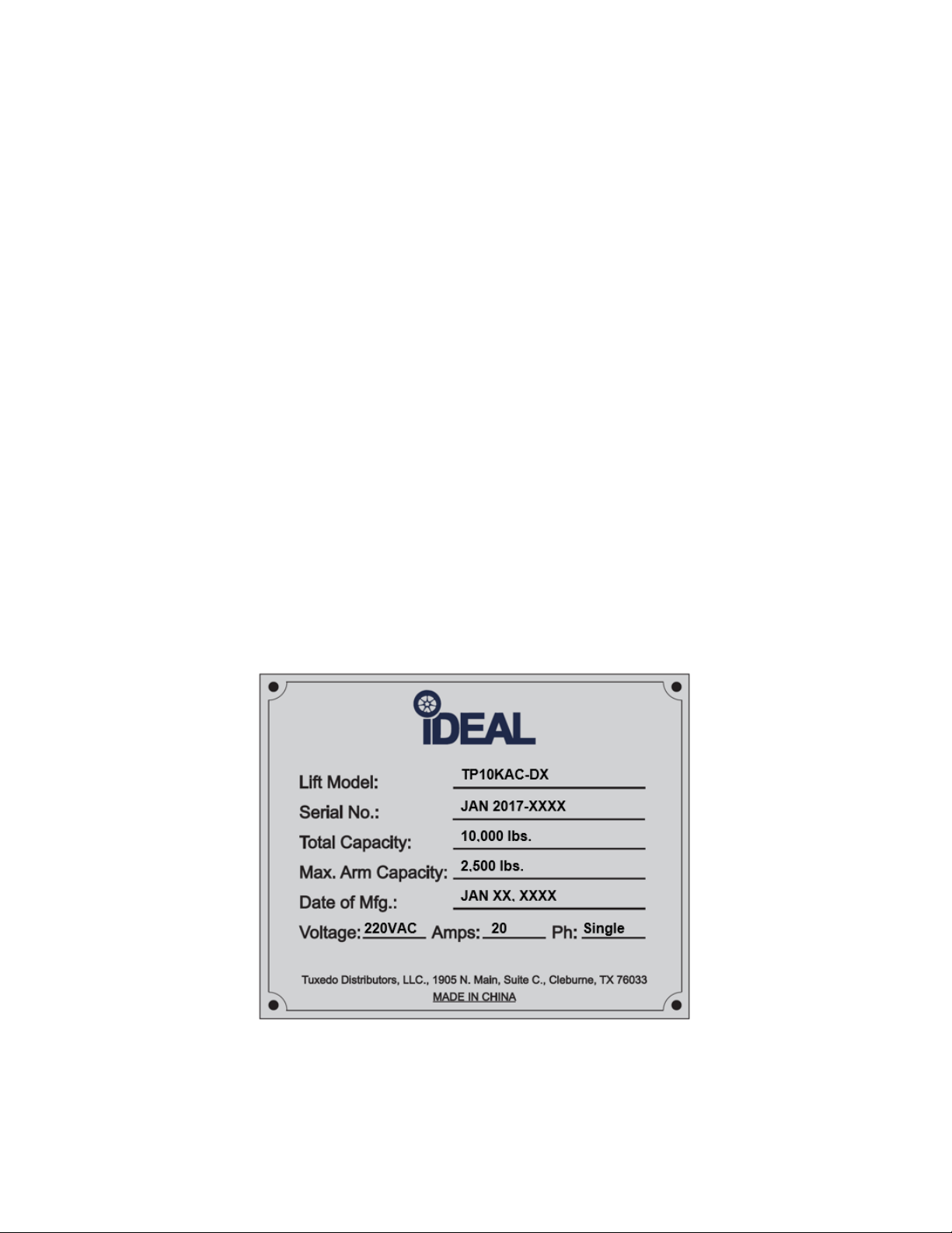
PRODUCT IDENTIFICATION
IMPORTANT
SAVE THESE INSTRUCTIONS
2
TP10KAC-DX
July 2017
Page 3

OWNER / EMPLOYER OBLIGATIONS
1. The Owner/Employer shall ensure that lift operators are qualified and that they are trained in the
safe use and operation of the lift using the manufacturer’s operating instructions; ALI/SM10-1, ALI
Lifting it Right safety manual; ALI/ST-10 ALI Safety Tips card; ANSI/ALI ALOIM-2008 (R2013),
American National Standard for Automotive Lifts - Safety Requirements for Operation,
Inspection and Maintenance; ALI/WL101 Series, ALI Uniform Warning Label
Decals/Placards; and in the case of frame engaging lifts, ALI/LP-GUIDE, Vehicle Lifting
Points/Quick Reference Guide for Frame Engaging Lifts.
2. The Owner/Employer shall establish procedures to periodically inspect the lift in accordance with
the lift manufacturer’s instructions or ANSI/ALI ALOIM-2008 (R2013), American National
Standard for Automotive Lifts - Safety Requirements for Operation, Inspection and
Maintenance; and the Employer shall ensure that the lift inspectors are qualified and that they are
adequately trained in the inspection of the lift.
3. The Owner/Employer shall establish procedures to periodically maintain the lift in accordance with
the lift manufacturer’s instructions or ANSI/ALI ALOIM-2008 (R2013), American National
Standard for Automotive Lifts - Safety Requirements for Operation, Inspection and
Maintenance; and the Employer shall ensure that the lift maintenance personnel are qualified and
that they are adequately trained in the maintenance of the lift.
4. The Owner/Employer shall maintain the periodic inspection and maintenance records
recommended by the lift manufacturer’s instructions or ANSI/ALI ALOIM-2008 R2013), American
National Standard for Automotive Lifts - Safety Requirements for Operation, Inspection and
Maintenance.
5. The Owner/Employer shall display the lift manufacturer’s operating instructions; ALI/SM 10-1, ALI
Lifting it Right safety manual; ALI/ST-10 ALI Safety Tips card; ANSI/ALI ALOIM-2008 (R2013),
American National Standard for Automotive Lifts - Safety Requirements for Operation,
Inspection and Maintenance; ALI/WL Series, ALI Uniform Warning Label Decals/Placards; and
in the case of frame engaging lifts, ALI/LP- GUIDE, Vehicle Lifting Points/Quick Reference
Guide for Frame Engaging Lifts in a conspicuous location in the lift area convenient to the
operator.
6. The Owner/Operator shall provide necessary lockout/tag out means for energy sources per ANSI
Z244.1-1982 (R1993), Safety Requirements for the Lockout / Tag out of Energy Sources,
before beginning any lift repairs and maintenance.
3
TP10KAC-DX
July 2017
Page 4

7. The Owner/Employer shall not modify the lift in any manner without the prior written consent of the
manufacturer.
IMPORTANT SAFETY INSTRUCTIONS
When using this lift, basic safety precautions should always be followed,
including the following:
1. Do not raise a vehicle on the lift until the installation is completed as described in this manual.
2. Always position the arms and adapters properly out of the way before pulling the vehicle into,
or out of the bay. Failure to do so could damage the vehicle and/or the lift.
3. Do not overload the lift. The capacity of the lift is shown on cover of this document and on the
lift’s serial number tag.
4. Note that the removal or installation of some vehicle parts may cause a critical load shift in the
center of gravity and may cause the vehicle to become unstable. Refer to the vehicle
manufacturer’s service manual for recommended procedures.
5. Positioning the vehicle is very important. Only trained technicians should position the vehicle
on the lift. Never allow anyone to stand in the path of the vehicle as it is being positioned and
never raise vehicle with passengers inside.
6. Position the arms to the vehicle manufacturer’s recommended pickup points. Raise the lift until
contact is made with the vehicle. Make sure that the arms have properly engaged the vehicle
before raising the lift to a working height.
7. Keep everyone clear of the lift when the lift is moving, the locking mechanism is disengaged, or
the vehicle is in danger of falling.
8. Unauthorized personnel should never be in the shop area when the lift is in use.
9. Inspect the lift daily. The lift should never be operated if it has damaged components, or is
malfunctioning. Only qualified technicians should service the lift.
10. Replace damaged components with manufacturer’s parts, or equivalent.
11. Keep the area around the lift clear of obstacles.
12. Never override the self-returning lift controls.
13. Use safety stands when removing or installing heavy vehicle components.
14. Avoid excessive rocking of the vehicle when it is on the lift.
4
TP10KAC-DX
July 2017
Page 5

15. To reduce the risk of personal injury, keep hair, loose clothing, fingers, and all body parts away
the equipment.
from moving parts.
16. To reduce the risk of electric shock, do not use the lift when wet, do not expose the lift to rain.
17. To reduce the risk of fire, do not operate equipment in the vicinity of open containers of
flammable liquids (gasoline).
18. Use the lift only as described in this manual, use only manufacturer’s recommended
attachments.
19. Unusual vehicles, such as limousines, RV’s, and long wheelbase vehicles, may not be suitable
for lifting on this equipment. If necessary, consult with the manufacturer or the manufacturer’s
representative.
20. The troubleshooting and maintenance procedures described in this manual can be done by the
lift’s owner/employer. Any other procedure should only be performed by trained lift service
personnel. These restricted procedures include, but are not limited to, the following: cylinder
replacement, carriage and safety latch replacement, leg replacement, over-head structure
replacement.
21. Anyone who will be in the vicinity of the lift when it is in use should familiarize themselves with
following Caution, Warning, and Safety related decals supplied with this lift, and replace them if
they are illegible or missing.
WARNING!! Failure by purchaser to provide the recommended mounting surface could result
in unsatisfactory lift performance, property damage, or personal injury.
For additional safety instructions regarding lifting, lift types, warning labels, preparing to lift, vehicle
spotting, vehicle lifting, maintaining load stability, emergency procedures, vehicle lowering, lift
limitations, lift maintenance, good shop practices, installation, operator training and owner/employer
responsibilities, please refer to “Lifting It Right” (ALI/SM) and “Safety Tips” (ALI/ST) and vehicle
lift points for service garage lifting SAE J2184.
For additional instruction on general requirements for lift operation, please refer to “Automotive LiftSafety Requirements for Operation, Inspection and Maintenance” (ANSI/ALI ALOIM).
Installation shall be performed in accordance with ANSO/ALI ALIS, Safety Requirements for
Installation and Service of Automotive Lifts.
LOCATION
This lift has been evaluated for INDOOR USE ONLY with an operating ambient temperature range of
5 - 40°C (41-104°F)
ATTENTION! This lift is intended for indoor installation only. It is prohibited to install this
product outdoors. Operating environment temperature range should be 41 – 104 °F (5 – 40 °C).
Failure to adhere will result in decertification, loss of warranty, and possible damage to
5
TP10KAC-DX
July 2017
Page 6
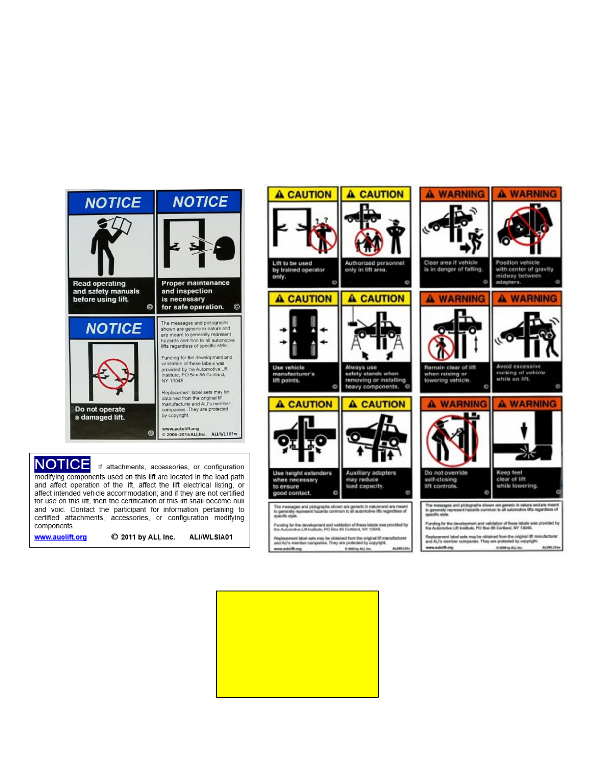
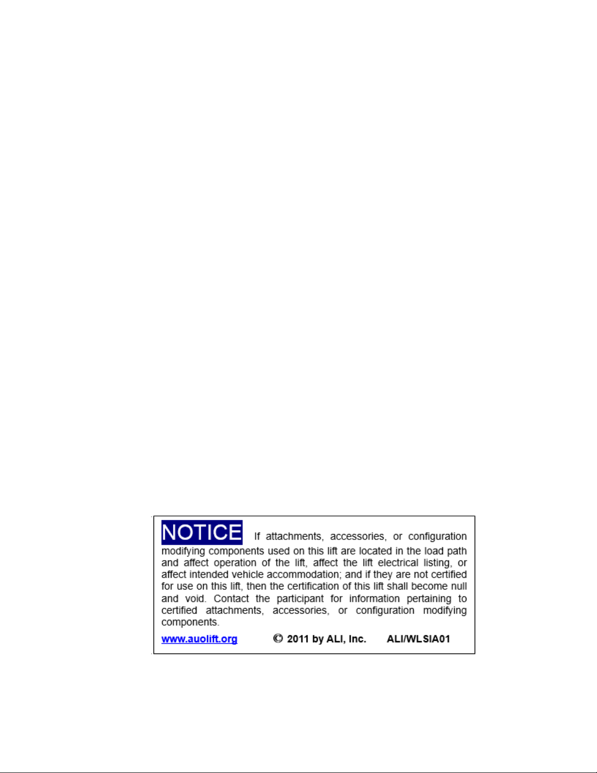
SAFETY DECALS
10,000 LBS.
These Decals Must Be Applied to Lift.
NOTE: SOME IMAGES IN THIS MANUAL ARE GENERIC AND MAY NOT RESEMBLE THE LIFT
YOU HAVE PURCHASED.
REFERENCE: AUTOMOTIVE LIFT INSTITUTE, Inc.
CAUTION
RELEASE ALL LATCHES
BEFORE LOWERING LIFT
MAXIMUM CAPACITY
6
TP10KAC-DX
July 2017
Page 7
IMPORTANT INFORMATION
Please deliver this manual to the lift owner and/or operator along with all other documentation
provided with the lift. Failure to operate this equipment as intended may cause injury or death.
1. Read this manual thoroughly before installing, operating, or maintaining this lift.
2. This lift is designed for indoor use only, and should not be installed in a pit or depression.
3. The floor on which the lift is to be installed must be 4-1/4” minimum thickness concrete,
with a minimum compressive strength of 3,000 psi.
4. The lift has specific electrical requirements as described in the Installation Instructions
section of this manual.
5. This lift has a minimum ceiling height requirement as described in the Installation
Instructions section of this manual.
6. It is recommended that the lift to be located 10’ – 12’ from the nearest obstruction in
front of the lift and 2’ – 3’ from the nearest obstruction on each side of the lift.
7. Failure by the owner to provide the recommended shelter, mounting surface, electrical
supply, and ceiling height could result in unsatisfactory lift performance, property damage, or
personal injury.
8. The operation of the lift is permitted by authorized person only.
9. Lift buyers are responsible for any special regional structural and/or seismic anchoring
requirements specified by any other agencies and/or codes such as the Uniform Building
Code (UBC) and/or International Building Code (IBC). When required, it is recommended to
contact a qualitied engineer to address the specific UBC and/or IBC code requirements.
7
TP10KAC-DX
July 2017
Page 8
1. PRODUCT INFORMATION
1.1 Product Description
The TP10KAC-DX 2-post hydraulic lift is a surface mounted, frame contact lift incorporating the latest safety
technologies. Designed and manufactured for a lifting capacity of 10,000 lbs. (Max 2,500 lbs. per Lifting Arm)
and is fully capable for lifting vehicles, vans and light trucks by safely holding them in an elevated position.
The TP10KC-DX also incorporates the Bi-Symmetric feature, which allows the Arms to be configured for both
asymmetrical & symmetrical lifting configurations.
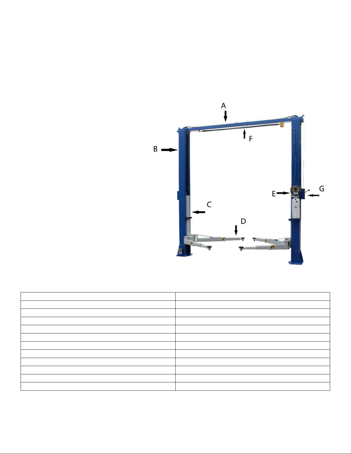
The TP10KC-DX 2-post hydraulic lift
consists of a fixed structural unit
(Crossbeam and Columns), the mobile
units (Carriages and Lift Arms), and the
Hydraulic Power System and Safety
devices.
A. Crossbeam
B. Column
C. Carriage
D. Lifting Arm
E. Power Unit
F. Overhead Safety Shut-Off Bar
G. Single Point Safety-Latch
Release
1.2 Technical Data
Capacity
Height Overall
Width Overall w/ Power Unit
Max Lifting Height
Max Lifting Height w/ Tallest Adaptor
Width Between Columns
Min Pad Height
Drive Thru Clearance
Front Arm Reach – Min / Max
Rear Arm Reach – Min / Max
Electrical Power
Max Hydraulic Pressure
TP10KAC-DX
10,000 lbs. (
Max 2,500 lbs. per Arm)
144”
145-1/2”
71”
76-1/2”
116”
4”
104”
23” – 45”
41” – 57”
220V, 20 Amp, 1 Phase
3,050 PSI
8
July 2017
Page 9
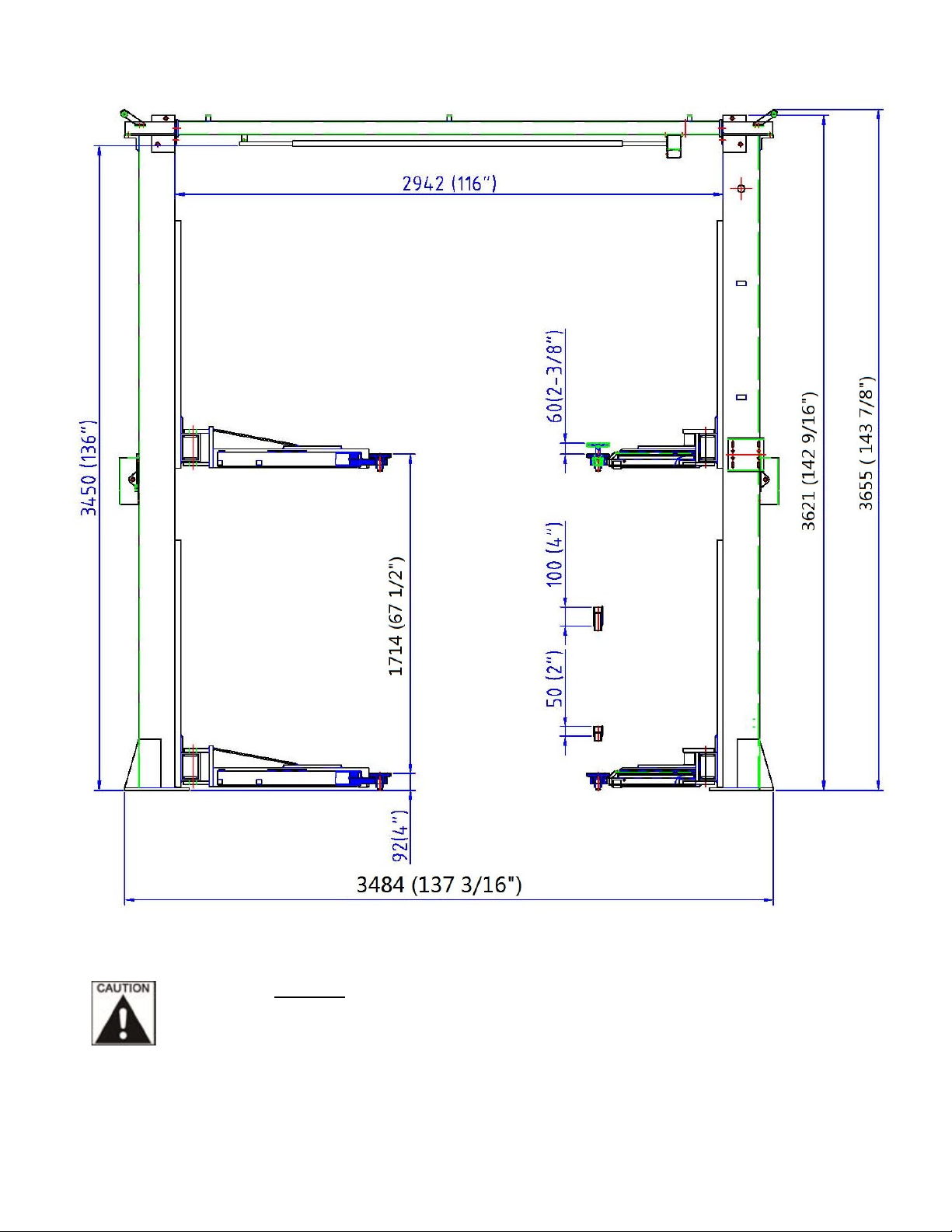
Figs. 1 & 2 Elevation & Floor Layout
Fig. 1 - Elevation View
POWER UNIT MUST BE INSTALLED ON THE PASSENGER SIDE. FAILURE TO DO SO CAN RESULT
WITH INTERFERECE BETWEEN THE POWER UNIT AND SHORT SWING ARM, THUS CAUSING
DAMAGE TO POWER UNIT.
9
TP10KAC-DX
July 2017
Page 10
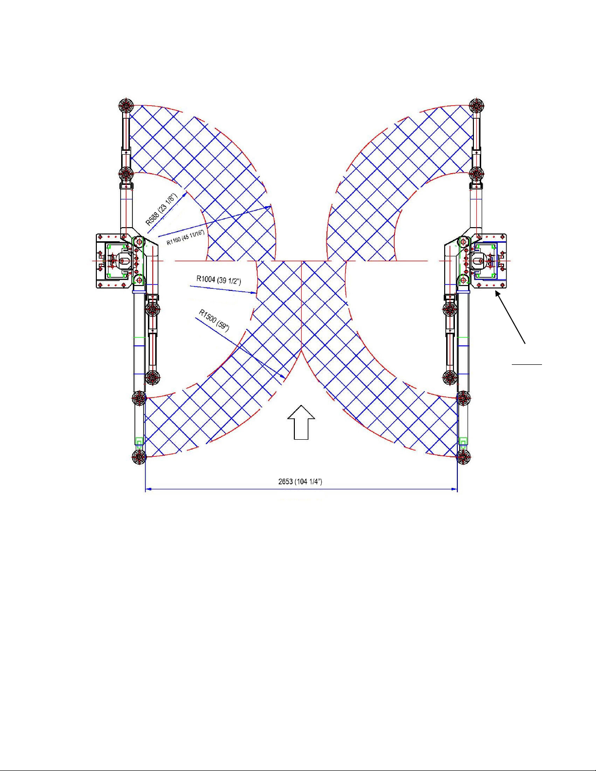
Bi-Symmetric (Asymmetric & Symmetric) Configurations
Fig. 2 - Floor Layout
NOTE:
Power Unit must be
mounted on
Passenger Side,
beside the long/rear
Swing Arm.
10
TP10KAC-DX
July 2017
Page 11

2. INSTALLATION
2.1 Site Selection
The hydraulic lift is designed only for indoor use. Application in a room with explosion hazard is not permitted.
Setting in a wet place, a car wash center for instance, is prohibited.
2.2 Surface Condition / Foundation & Anchoring
The 2-post hydraulic lift should be installed on level ground. The foundation must be 4-1/4” minimum thickness
concrete, with a minimum compressive strength of 3,000 psi. Failure to meet the foundation requirement may
cause the lift instability or personal injury. Installing on asphalt, soft clay floor or near the expansion gap is
prohibited.
FOUNDATION and ANCHORING REQUIREMENTS
1. Concrete shall have compression strength of at least 3,000 PSI and a minimum thickness of 4-1/4” in order to
achieve a minimum anchor embedment of 3-1/4”. NOTE: When using the standard supplied 3/4” x 5-1/2” long
anchors, if the top of the anchor exceeds 2-1/4” above the floor grade, you DO NOT have enough embedment.
2. Maintain a 6” minimum distance from any slab edge or seam. Hole to hole spacing should be a minimum 6” in
any direction. Hole depth should be a minimum of 4-1/4”.
3. DO NOT install on asphalt or other similar unstable surface. Columns are supported only by anchoring to floor.
4. Using the horseshoe shims provided, shim each column base as required until each column is plumb. If one
column has to be elevated to match the plane of the other column, full size base shim plates should be used.
Torque anchors to 110 ft-lbs. Shim thickness MUST NOT exceed 1/2” when using the 5-1/2” long anchors
provided with the lift.
5. If anchors do not tighten to 110 ft-lbs. installation torque, replace the concrete under each column base with a
4’ x 4’ x 6” thick 3,000 PSI minimum concrete pad keyed under and flush with the top of existing floor. Allow
concrete to cure before installing lifts and anchors (typically 2 to 3 weeks).
ANCHORING TIPS
1. Use a concrete hammer drill with a carbide tip, solid drill bit the same diameter as the anchor, 3/4” -
(.775 to .787 inches diameter). Do not use excessively worn bits or bits which have been incorrectly sharpened.
2. Keep the drill in a perpendicular line while drilling.
3. Let the drill do the work. Do not apply excessive pressure. Lift the drill up and down occasionally to remove
residue to reduce binding.
4. Drill the hole to depth of 2” deeper than the length of anchor. NOTE: Drilling thru concrete (recommended) will
allow the anchor to be driven thru the bottom of foundation if the threads are damaged or if the lift will need to be
relocated.
5. For better holding power blow dust from the hole.
6. Place a flat washer and hex nut over threaded end of anchor, leaving the nut almost flush with the top of the
anchor bolt. Carefully tap anchor into hole. Do not damage threads. Tap anchor into the concrete until nut and
flat washer are against base plate. Do not use an impact wrench to tighten! Tighten the nut, two or three turns on
average after the concrete has cured (28-day cure). If the concrete is very hard only one or two turns may be
required.
11
TP10KAC-DX
July 2017
Page 12

FOUNDATION and ANCHORING REQUIREMENTS, Fig 3
Drill holes using 3/4” Clean hole. Run nut down just Tighten nut with
carbide tipped
masonry drill bit per
ANSI standard
B94.12.1977
below impact section Torque wrench to
of bolt. Drive anchor 110 ft.-lbs.
into hole until nut and
washer contact base.
2.3 Tools & Equipment Required
• 12 quarts of Non-Detergent / Non-Foaming Hydraulic Oil - SAE-10, AW 32 or equivalent
• Chalk line and 12’ Tape Measure
• Concrete hammer drill with 3/4” bit
• 11/16” open end wrench
• 3/4” open end wrench
• Torque wrench
• 15/16” deep socket or wrench
• 1-1/8” socket
• 13/16” open end wrench
• Level (18” minimum length)
• Vise grips
• Tape measure
• Funnel
• Hoist or Forklift (optional)
• Two 12’ step ladders
• 1/4” drive ratchet with 5/16” socket
12
TP10KAC-DX
July 2017
Page 13

2.4 Installation Procedure
1. Read this manual thoroughly before Installing, Operating, or Maintaining this lift.
2. Site Evaluation and Lift Location
A. Always use an architect’s plan when provided. Before unpacking the lift entirely, determine if the
site is adequate for the lift model being installed see figures 1 & 2 for typical bay layout and ceiling
height requirements. It is recommended to have 144” (12’) minimal celling height.
B. Snap chalk lines to identify the lift’s centerline.
C. Snap a chalk line parallel to the lift’s centerline, spaced 9.00” toward the rear of the bay. This line
represents the back edge of the column bases.
D. Snap chalk lines parallel to the lift’s centerline spaced 68-7/8” to the left and 68-7/8” to the right.
These lines represent the APPROXIMATE outside edges of the column bases.
DO NOT USE THESE LINES TO POSITION THE COLUMNS, FOLLOW THE INSTRUCTIONS IN
THIS MANUAL.
3. Unpack the Lift
A. Remove the swing arms, bolt box, power unit box, and overhead beam.
B. Save all packing hardware, as these components are necessary to complete the installation.
C. Remove the 1/2” bolts from the uprights which hold the two columns together.
D. Remove the upper column. Do not stand the columns up now but lay the columns with their flat
backs on the floor.
4. Attach Cylinder Mounts
A. Connect cylinder mounts to top of each column using 4ea 1/2” x 1-3/4” bolts, washers and nuts
provided as shown in figures 4a & 4b.
Fig. 4a Fig. 4b
13
TP10KAC-DX
July 2017
Page 14

5. Install Hydraulic Cylinders
A. Install the cylinder to the cylinder mounts (uprights) with 9/16” x 4-1/2” pins, cylinder bushings
(spacer) washers, and snap rings, as in figure 5a. The hose connecting port near the other end
of the cylinder should be positioned pointing to the column’s opening. (Fig. 5b)
B. Bolt the cylinder rods to the carriages. (Fig. 5c)NOTE: MAKE SURE SNAP RING ON CYLINDER
ROD IS IN SECURED IN GROOVE.
Fig. 5a
Fig. 5b Fig. 5c
DO NOT HOLD THE CYLINDER ROD IN A WAY THAT COULD DAMAGE THE FINISH. CYLINDER
LEAKS CAUSED BY DAMAGED RODS ARE NOT COVERD UNDER WARRANTY.
6. Columns Positioning & Main Side Column Anchoring
A. Carefully stand up the Main side column (w/ power unit bracket) & Off side column, position
the columns where they are to be secured. Ensure column’s openings are facing each other.
THE MAIN SIDE COLUMN MUST BE POSITIONED TO BE ON THE PASSENGER SIDE OR RIGHT
SIDE WITH THE VEHICLE HEADED FORWARD. THE DISTANCE BETWEEN COLUMN’S BACK
EDGE TO WALL, SHOULD BE AT LEAST 2 FEET FOR SAFETY.
B. Using the column base as a template, drill the anchor bolt holes for the Main side column only!
(Refer to FOUNDATION REQUIREMENTS & ANCHORING TIPS ON PAGES 12 & 13)
NOTE: DO NOT ANCHOR OFF SIDE COLUMN AT THIS TIME!
C. Install the anchor bolts, assemble washers & nuts onto the anchor bolts. Thread the nuts onto the
anchors bolts where the tops of the nuts are just above the top of the anchor bolts. Carefully tap
the anchor bolts into the concrete until the washer rests against the base plate. Ensure not to
damage threads.
D. Using a level, plumb the Main side column both side to side and front to back. Shim the leg as
necessary using the Shims provided. Tighten anchor bolts to 110 ft. lbs. as noted on page 9. Recheck to ensure column is plumb.
NOTE: REFER TO ‘FOUNDATION & ANCHOR REQUIREMENTS’ IF MORE THAN 1/2” OF
SHIMS ARE REQUIRED.
E. Ensure Off side column is in the correct location. DO NOT DRILL HOLES FOR ANCHORS at this
time.
14
TP10KAC-DX
July 2017
Page 15

7. Install Overhead Limit Switch & Overhead Beam (Figs. 6a, 6b & 6c)
Position Overhead Limit Switch
Overhead Limit
Overhead Limit
A. Install overhead limit switch assembly to overhead beam, using 2ea 1/4”-20 Bolt & Lock Nuts as
shown in figs 6a, 6b & 6c.
B. Slide end of padded bar (without a mounting hole) through the slot in the overhead switch
assembly. Connect the padded bar to the inside hole in the overhead beam using a spacer and
1/4”-20 Bolt & Lock Nut
Fig. 6a Fig. 6b
Assembly on same side as power unit.
Switch Assembly
Switch Cable
Fig. 6c
15
TP10KAC-DX
July 2017
Page 16

8. Install Overhead Beam
Position Overhead Limit Switch
A. Install cylinder mounts (uprights) using 2ea 1/2” x 1-3/4” bolts, washers & nuts on each end, (Figs.
7a, 7b, 7c). NOTE: ENSURE OVERHEAD LIMIT SWITCH ASSEMBLY IS ON THE MAIN SIDE
COLUMN SIDE.
Fig. 7a Fig. 7b
9. Anchoring Off Side Column
A. Using a level, check the alignment and
plumbness of the entire structure. Plumb the off
side column both side to side and front to back.
B. The base of the column may vary from the
preliminary layout, as it is more important that
the column be perpendicular to the floor and
parallel to the other column.
C. Install the anchor bolts and shim the base as
described in Step #6
Assembly on same side as power unit.
Fig. 7c
16
TP10KAC-DX
July 2017
Page 17

10. Equalization Cable Routing
A. The carriages should be resting on the same column latches for proper equalization. Ensure to
measure the height above the baseplate to each carriage. The measurement should be within 3/8”
of each other.
Fig. 8a Fig. 8b
B. Using the diagrams, route the equalization cables according to figs. 8a, 8b & 8c (Cable Routing
Diagram next page) from carriage to carriage through the cable rollers. Secure to carriages using
Nylon Hex Nuts & Washers. Ensure that cables are not crossed together. Take out slack but DO
NOT TIGHTEN CABLES AT THIS TIME.
C. After equalizations cables are routed and connected to carriages, take out the slack in both cables
by turning down the nuts on top of each carriage top. Use vise grips to hold the cable end, but be
very careful not to damage the threads.
NOTE: CARRIAGES MUST REMAIN AT THE SAME COLUMN LOCK HEIGHT POSITION WHILE
CABLES ARE BEING TIGHTENED. FAILURE TO DO WILL CAUSE THE CARRIAGES SAFETY
LATCHES TO BE OUT OF SYNC.
D. Alternately tighten the cable nuts at both carriages until the cables are tightened. The correct
tension in the cables are indicated by being able to pull the cables together with approximately 15
lbs. effort at midpoint in the column. If the cables are installed correctly, both carriages will raise
together.
17
TP10KAC-DX
July 2017
Page 18

EQUALIZATION CABLE ROUTING DIAGRAM
Fig. 8c - Cable Routing Diagram
11. Install the Hydraulic Fittings, Hoses and Return Lines
When attaching hydraulic fittings with pipe threads to the cylinders use Teflon tape. DO NOT start
the Teflon tape closer than 1/8” from the end of the fitting. Failure to comply may cause damage
to the Hydraulic system.
When tightening connections with flared (JIC) fittings, always follow the following tightening
instructions. Failure to follow the below instructions may result in cracked fitting and/or leaks.
Use the proper size wrench.
The nut portion of the fitting is the only part that should turn during tightening. The flare
seat MUST NOT turn.
Screw the fittings together hand tight.
Rotate the nut portion of the fitting 2-1/2 hex flats.
Back the fitting off one full turn.
Again, tighten the fitting hand tight, and then rotate the nut portion of the fitting 2-1/2 hex
flats.
18
TP10KAC-DX
July 2017
Page 19

A. Fittings & Hoses Connections:
Main Side Column
Off Side Column
T-Fitting /
1. First screw on the hose fitting connectors on the cylinder’s lower end ports. (Fig. 9a)
2. Connect the longest hose from the cylinder in Off side column to the top of Main side
column. Remember to rout the hose through the hook on cross beam. (Fig. 9b & 9c)
3. Then from the T-fitting inside column, connect the shortest length hose directly down to
the main inside cylinder connector. (Fig. 9d)
4. Another middle length hose from the T-fitting goes to the motor pump through a hole on
the side of the column. (Fig. 9d)
5. Pull hoses upward taking out any slack between the cylinder fitting ports and the
cylinder mounts. Secure hoses to main side cylinder with wire tie around the T-Fitting
and the cylinder. The T-Fitting should be positioned to aim directly out through the
grommet, fig 9d. Secure Offside hose to cylinder at the same height with a wire tie.
Fig. 9a Fig. 9b
B. Return Line Connection (blue plastic tubing)
Fig. 9c Fig 9d
1. Screw in an elbow air-line fitting on the top end of the off side cylinder (Fig. 9b).
2. Screw in another T air-line fitting on the top end of main side cylinder also. (Fig. 9c)
3. Connect the return line from off side cylinder to main side cylinder with press-lock
fittings. The tubing section off other end of T-fitting will be routed to power unit.
Grommet
19
TP10KAC-DX
July 2017
Page 20

12. Mounting Power Unit
Off Side Column
Main
Side Column
A. Mount on the motor pump using 5/16” x 1-1/4” bolts
and nylon nuts provided in the bolt box to Main side
column.
B. Connect the ‘blue’ Return Line to the 90 degree air
fitting, on side of valve block as shown in ( Fig 10)
C. Connect the hydraulic hose to the 90 degree fitting,
on side of valve block, as shown in (Fig 10).
13. Latch-Release Cable Wiring & Accessories mounting.
A. Mount the safety latch device on each column as shown in ( Fig. 11a & 11b)
Fig. 10
Fig. 11a Fig. 11b
20
TP10KAC-DX
July 2017
Page 21

(
Off Side Column
) (Main
Side Column
)
B. Mount the Cable Pulley and Support Bracket on the top of the Columns. (Fig. 11c)
C. Route and adjust the cable tension so that when the handle is pressed down, both latches will be
released.
D. Install covers for both latch devices on Off Side & Main Side columns, using the provided screws.
(Figs. 12a & 12b)
Fig. 11c
Fig. 12a Fig. 12b
21
TP10KAC-DX
July 2017
Page 22

14. Install Arm Restraints & Lifting Arms
Gear
Pawl
Swing Arm
Limit Bolt / Nut
A. Position the arm restraint gears with pin against the bottom of the arms in the orientation shown in
Fig.13a. Attach the gears to the arms with bolts. Do not tighten at this time.
Pin
Fig. 13a Fig. 13b
B. Position the arm restraint pawls on the carriage to mate with the gears on the arms.
C. Install the swing arms to the carriages using the pins, as shown in Fig. 13a & b. Secure pin to
carriage with clip at bottom of pin.
Suggestion: Position Long Arms to rear or ‘drive-in’ end of the lift, with Short Arms (L&R) to the front.
DON’T FORCE THE GEARS, IT MAY BE NECESSARY TO PULL UP ON THE RESTRAINT ACTUATOR PIN
IN ORDER TO INSTALL THE SWING ARM PIN.
D. Tighten the arm restraint gear bolts to 30 – 34 ft. lbs.
E. Assemble the arm extensions & lifting pads. Limit arm extensions with bolt & nuts. (Fig.14a & 14b)
Fig. 14a (Front Arm)
22
TP10KAC-DX
July 2017
Page 23

Fig. 14b (Rear Arm)
Limit Bolt / Nut
15. Filling Reservoir Tank
A. Remove the fill level screw of the power unit tank. Fill it with
Hydraulic Oil - SAE-10, AW 32 or equivalent
.
Non-Detergent / Non-Foaming
, until fluid reaches the bottom of the screw hole.
Replace the fill screw.
16. Lubricate the four inside corners of both columns with heavy duty grease.
17. Electrical Connection to Power Unit & Overhead Limit Switch
A. Have a certified electrician make the electrical connection from power supply to the power unit. Use
separate circuit for each power unit, as shown below in (Fig. 15).
B. Have a certified electrician make the electrical connection for the overhead limit switch to power unit’s
switch box, as shown in (Fig. 15).
Fig. 15
Electrical Wiring must comply with local code. Protect each circuit with time delay fuse or
circuit breaker. For 208V-230V single phase, use 20 amp fuse.
Never operate the motor in line voltage less than 208VAC as motor damage may occur.
23
TP10KAC-DX
July 2017
Page 24

18. Testing
In this step A, there is no load on the lift.
Cycle up and down must be with interval rest of 2 mins.
A. Without a load, raise the lift empty to the top of its travel and lower it to the floor three (3) times to
remove the remaining air from the hydraulic system.
B. The latches should click close together as the lift is being raised. If not, adjust cables for proper
equalization and tightness.
C. When the carriages are lowered onto the locks, the Latch Release Handle should NOT be capable
of being pulled down. Prior to lowering the carriages, always raise up enough to free the latches,
then pull down the latch release handle to unlock the carriages to lower. Ensure both latches
properly release.
D. The first time a vehicle is placed on the lift, raise it no higher than three feet. Lower the vehicle onto
the safety latches. Raise the lift a few inches and pull latch release lever then lower the vehicle to
the floor.
E. Raise the vehicle to full height and lower the carriages onto the safety latches. Lower the vehicle to
the floor.
F. After cycling the lift ten times with a vehicle on it, recheck the tightness of the anchors to at least
110 ft-lbs.
The Lift is now ready for Operation.
24
TP10KAC-DX
July 2017
Page 25

3. Operation
BE SURE TO READ AND FAMILIARIZE YOURSELF WITH THE SAFETY INSTRUCTIONS AT THE
BEGINNING OF THIS MANUAL. FAILURE TO FOLLOW SAFETY INSTRUCTIONS MAY RESULT IN
PROPERTY DAMAGE, PERSONAL INJURY OR DEATH.
3.1 Operating Instructions
BE SURE TO READ AND FAMILIARIZE YOURSELF WITH THE SAFETY INSTRUCTIONS AT THE
BEGINNING OF THIS MANUAL. FAILURE TO FOLLOW SAFETY INSTRUCTIONS MAY RESULT IN
PROPER DAMAGE, PERSONAL INJURY OR DEATH.
TO AVOID PERSONAL INJURY AND/OR PROPERTY DAMAGE, PERMIT ONLY TRAINED PERSONNEL
TO OPERATE LIFT. AFTER REVIEWING THESE INSTRUCTIONS, GET FAMILIAR WITH LIFT CONTROLS
BY RUNNING THE LIFT THROUGH A FEW CYCLES BEFORE LOADING VEHICLE ON THE LIFT
ALWAYS LIFT THE VEHICLE USING ALL FOUR ADAPTERS. NEVER RAISE JUST ONE END, ONE
CORNER, OR ONE SIDE OF VEHICLE.
3.1.1 Lift Preparation
Lift arms must be fully lowered and service bay clear of all personnel before the vehicle be brought into the
bay. Configure Swing arms to drive-thru position.
.
3.1.2 Vehicle Positioning
a. Positioning the vehicle between columns.
b. Adjust lift arms so that the vehicle is positioned with the center of gravity between the pads.
Make sure the arm restraints are fully engaged.
c. Raise the lift by pressing the lifting button on power unit until the lifting pad adaptors contact
underside of the vehicle.
d. Make sure the vehicle is secured.
3.1.3 Loading Lift
Swing arms under vehicle and position adapters at vehicle manufacturer’s recommended lift points. Use
intermediate, high step, or optional adapters for under body clearance when required.
Also see Vehicle Lifting Points on Page 27 for additional information.
3.1.4 To Raise Lift
a. Push START button of the motor pump.
b. Stop before arms making contact with vehicle. Check arm restraint pins for engagement. If
required, slightly move arm to allow restraint gear and pawl to match. DO NOT hammer pin
down, as this will damage the restraint gear teeth.
c. Raise vehicle until the wheels slightly clear the floor, then release the START button.
25
TP10KAC-DX
July 2017
Page 26

d. Check support adapters for secure contact at vehicle manufacturer recommended lift points.
e. Continue to raise to desired height only if vehicle is secure on lift. Then release the START
button.
f. DO NOT go under vehicle if all four adapters are not in secure contact at vehicle manufacture
recommended lift point.
g. Repeat complete spotting, loading and raising procedures if required.
h. Press down the hydraulic pressure release lever on the motor pump to lower the vehicle into the
locking position. The locking latches are engaged.
DO NOT GO UNDER VEHICLE IF LOCKING LATCHES ARE NOT ENGAGED.
BEFORE ATTEMPTING TO LIFT PICKUP TRUCKS OR OTHER TRUCK FRAME VEHICLES,
BE SURE THAT:
• Vehicle frame is strong enough to support its weight and has not been weakened by
modification or corrosion.
• Vehicle individual axle weight does not exceed one-half lift capacity.
• Adapters are in secure contact with frame at vehicle manufacturers recommended lift point.
• Vehicle is stable on lift
• The overhead switch bar will contact the highest point on the vehicle
3.1.5 While Using Lift
a. Avoid excessive rocking of vehicle while on lift.
b. Always use safety stands as needed or when removing or installing heavy components.
3.1.6 To Lower Lift
a. Remove all tools or other objects from lift area
b. Press START button a few seconds to raise up a little. Then pull down on the single point, latch-
release handle with one hand, while at the same time pressing down on the power unit’s pressurerelease lever with the other hand.
REMAIN CLEAR OF LIFT WHEN LOWERING VEHICLE. OBSERVE PINCH POINT WARNING DECALS.
3.1.7 Unloading Lift
After the lift is lowered down onto the ground, remove adapters from under vehicle and swing arms to full drivethru position before moving vehicle out.
IF LIFT IS NOT OPERATING PROPERLY, DO NOT USE UNTIL ADJUSTMENT OR REPAIRS ARE MADE BY
QUALIFIED LIFT SERVICE PERSONNEL.
26
TP10KAC-DX
July 2017
Page 27

Vehicle Lifting Points
Some vehicles may have the manufacturer’s Service Garage Lift Point locations identified by triangle
shape marks on its undercarriage (reference SAE J2184). There may also be a label located on the
right front door lock face showing specific vehicle lift points. If the specific vehicle lift points are not
identified, please refer to the “Typical Lift Points” illustration below or the ALI/LP Guide - Vehicle
Lifting Points / Quick Reference Guide included with your lift. Consider center of gravity, contents of
vehicle and weight shifting before operating.
Make sure the vehicle is neither front nor rear heavy. If the specific vehicle lift points are not
identified, or if the vehicle has additional or uniquely positioned payload, have a qualified person
calculate the vehicle center of gravity or have the vehicle center of gravity determined at a vehicle
scale. Load the vehicle with the center of gravity midway between adapters.
Unusual vehicles, such as limousines, RV’s, and long wheelbase vehicles, may not be suitable for
lifting on this equipment.
If necessary, consult with your iDEAL Automotive Equipment representative or contact the vehicle
manufacturer.
27
TP10KAC-DX
July 2017
Page 28

4. Inspection & Maintenance Instructions
Contact your service provider for instruction before starting up if you are not completely
familiar with automotive lift maintenance procedures. Only qualified personnel can perform
maintenance on this equipment. Any failure in operation may cause personal injury or
death.
Daily
Always keep bolts tight. Check periodically.
Always keep lift components clean.
Always if oil leakage is observed, contact your service provider.
Check cables and sheaves for wear every day. Replace worn or broken parts with lift
manufacturer’s parts, or their equivalent.
Monthly
Check equalizer cable tension.
Lubricate locking latch shafts. Push latch handle several times for oil to penetrate joints.
Lubricate the four inside corners of the columns with heavy duty bearing grease.
With lift lowered, check the hydraulic fluid level. If necessary add oil as described in the
Installation Instruction section of this manual
Check carriage latch synching: Latches should click at the same time. If necessary adjust
equalization cables.
Check tightness of all bolts.
Check the nuts for tightness every week for the first month, and every month afterwards.
Every 3 Months
Check anchor bolts for tightness. Anchors should be torque to 110 ft-lbs.
Check and clean the oil filter
Every 6 Months
Check fluid level of lift power unit and refill if required.
If Lift stops short of full rise or chatters, contact your service provider.
Replace all caution, warning or safety related decals on the lift if unable to read or missing
reorder labels from service provider.
Also, see ANSI/ALI ALOIM booklet for periodic Inspection Checklist and Maintenance Log Sheet.
ALWAYS REPLACE WORN PARTS WITH GENUINE, AUTHORIZED PARTS.
For Parts & Service Assistance
Please contact iDEAL Automotive Equipment @ Toll Free: 877-588-9337
(Also see Additional Information next two pages)
28
TP10KAC-DX
July 2017
Page 29

WIRE ROPE INSPECTION
Nom. Cable Diameters
Max. Reduction in Diameter
Up to 5/16”
1/64”
3/8” to 1/2”
1/32”
• Wire ropes are critical to the safe and reliable performance of your lift.
• Cables are expendable items and should be replaced as a set.
CABLE CONDITION GUIDE
(Maximum Allowable Cable Necking)
Typical Good Cable Cable with Necking
Cable with Corrision Cable with Broken Wires
WIRE ROPE REPLACEMENT CRITERIA
If any cable is found to be in need of replacement, the entire cable set, pulleys and
safety rollers, must be replaced immediately. See Cable Condition Guide.
The Wire Rope MUST be replaced if One or More of the Following Criteria Are Met:
• More than six (6) randomly distributed broken wires in one rope *lay or 6xd length.
• More than three (3) broken wires in one strand in one rope *lay or 6xd length.
• Three (3) or more broken wires at rope terminations.
• One outer wire broken at the point or contact with the core of the rope which has worked its way out of
the rope structure and protrudes or loops out from the rope structure.
• Heavy rusting, corrosion, or pitting. A light surface corrosion on outer wires is normal.
• Wear or scraping of one-third (1/3) of the original diameter of outside individual wires.
• Excessive stretch. It is normal for new cable to require adjustment during “break-in,” after which small
periodic adjustments may be required. However, if a cable that has been in service for 6 months should
suddenly require frequent adjustments or has used all the cable adjustments available, all cables must
be replaced immediately.
• Deformed strands, kinking, crushing, bird-caging, or any other damage or distortion of wire rope
structure.
• Variations in diameter (necking) or any change from normal appearance.
• Reductions from nominal diameter of more than 1/32” (for cables 3/8” to 1/2” diameter inclusive.)
• End attachments cracked, deformed or worn.
* Lay is the distance measured, parallel to the rope axis, in which a single strand makes one complete turnaround the
rope axis, or the wires make a complete turnaround the axis of the strand.
Also, reference ANSI/ALI ALOIM standard for more information on wire rope cable inspection.
29
TP10KAC-DX
July 2017
Page 30

Emergency Operation
(If Lift Becomes Inoperable In Raised Position)
If the lift becomes inoperable in the raised position, wait until electrical power is restored to the lift
before attempting to lower the vehicle.
DO NOT LOOSEN OR REMOVE HYDRAULIC CONNECTIONS OR FITTINGS UNDER
PRESSURE. SERIOUS INJURY OR DEATH COULD OCCUR.
If it is crucial for reasons of safety that the vehicle be lowered, please DO NOT attempt to do so on
your own without first contacting your local authorized service representative or distributor, who can
verbally walk you through the process or assist, in person, where necessary.
For assistance, please contact iDEAL Automotive Equipment @ Toll Free: 877-588-9337
30
TP10KAC-DX
July 2017
Page 31

5. Exploded View / Parts List
31
TP10KAC-DX
July 2017
Page 32

Parts List
For Parts & Service Assistance
Please contact iDEAL Automotive Equipment @ Toll Free: 877-588-9337
ITEM Tux P/N M-Ref P/N DESCRIPTION QTY
1-1 TP10KAC-DX-001.1
2 TP11KC-DX-002
3 TP11KC-DX-003
4 TP11KC-DX-004
5 TP11KC-DX-005
6 TP11KC-DX-006
7 TP11KC-DX-007
8 TP11KC-DX-008
9 TP11KC-DX-009
10 TP11KC-DX-010
11 TP11KC-DX-011
12 TP11KC-DX-012
13 TP11KC-DX-013
14 TP11KC-DX-014
15 TP11KC-DX-015
16 TP11KC-DX-016
17-1 TP10KAC-DX-017.1
18 TP11KC-DX-018
19-1 TP10KAC-DX-019.1
20 TP11KC-DX-020
21-1 TP10KAC-DX-021.1
22 TP11KC-DX-022
23 TP11KC-DX-023
24 TP11KC-DX-024
25 TP11KC-DX-025
26 TP11KC-DX-026
27 TP11KC-DX-027
28 TP11KC-DX-028
29 TP11KC-DX-029
30 TP11KC-DX-030
31 TP11KC-DX-031
32 TP11KC-DX-032
33 TP11KC-DX-033
34 TP11KC-DX-034
35 TP11KC-DX-035
36 TP11KC-DX-036
37 TP11KC-DX-037
38-1 TP10KAC-DX-038.1
39 TP11KC-DX-039
40 TP11KC-DX-040
41 TP11KC-DX-041
42 TP11KC-DX-042
43 TP11KC-DX-043
44-1 TP10KAC-DX-044.1
45 TP11KC-DX-045
46 TP11KC-DX-046
SJ12-01000-A00
5105-08012-000
SJ12-00018-A00
SJ12-00019-A00
5110-06012-000
SJ12-00005-000
SJ12-00015-000
5404-15012-000
SJ12-00010-000
5302-00006-000
SJ12-00008-000
5103-06020-000
5202-00006-000
SJ12-00006-000
5202-00008-000
5114-06010-000
SJ12-05001-000
SJ12-00016-000
SJ12-06000-000
SJ12-00004-000
SJ12-00001-000
5202-00014-000
5302-00014-000
5302-00020-000
SJ01-00032-000
SJ01-00007-000
SJ01-00033-000
SJ01-00001-000
SJ01-00029-000
SJ01-05000-000
5103-14045-000
5206-00008-000
SJ01-00011-000
SJ01-00014-000
SJ12-04000-000
SJ12-00003-000
SJ01-00015-000
SJ12-02000-A00
SJ01-00017-000
SJ12-00009-000
SJ12-00011-000
SJ12-00013-000
SJ12-00007-000
SJ12-00014-000
SJ01-00019-000
SJ01-00016-000
32
TP10KAC-DX
July 2017
Offside Column 1
Screw, M8 x 12mm 16
Height Adaptor 2" 4
Height Adaptor 4" 4
Screw, M6 x 12mm 24
Roller, D30 x 10mm 3
Pin #1 3
Cotter Pin, D1.5 x 12mm 3
Offside Cover #2 1
Flat Washer, D6 8
Small Bracket 1
Bolt, M6 x 20mm 2
Nut, M6 2
Bolt, D12 x 40mm 2
Nut, M8 2
Threaded Pin, M6 x 10mm 4
Offside Bracket 1
Spring #2 2
Safety Latch 2
Spring #1, D35 x D2.5 2
Latch Shaft, D20 x 92mm 2
Nut, M14 12
Washer, D14 28
Flat Washer, D20
Bearing
Pulley Shaft 2
Pin 6
Cable Pulley 6
Pin 2
Overhead Crossbeam 1
Bolt, M14 x 45mm 12
Lock Nut, M8 5
Overhead Shut-Off Bar 1
T-Fitting 1
Cylinder Mount Bracket 2
Large Bracket 2
Return Line #2 1
Mainside Column 1
Rubber Gromit 1
Mainside Cover #1 1
Handle Knob, D40 x M10 1
Latch Release Cable, 306" 2
Latch Release Handle 1
Spacer #2 2
Hydraulic Hose, 71” 1
Hydraulic T-Fitting 1
6
6
Page 33

47 TP11KC-DX-047
48 TP11KC-DX-048
49-2 TP10KAC-DX-049.2
49-3 TP10KAC-DX-049.3
50 TP11KC-DX-050
51 TP11KC-DX-051
52 TP11KC-DX-052
53 TP11KC-DX-053
54 TP11KC-DX-054
55 TP11KC-DX-055
56-1 TP10KAC-DX-056.1
57 TP11KC-DX-057
58 TP11KC-DX-058
59 TP11KC-DX-059
60-1 PU-220V SPX iDEAL
61-1 TP10KAC-DX-061.1
62-1 TP11KAC-DX-062.1
63 TP11KC-DX-063
65 TP11KC-DX-065
66 TP11KC-DX-066
67 TP11KC-DX-067
68 TP11KC-DX-068
69 TP11KC-DX-069
70 TP11KC-DX-070
71-1 TP11KC-DX-071.1
72 TP11KC-DX-072
73 TP11KC-DX-073
74 TP11KC-DX-074
75 TP11KC-DX-075
76 TP11KC-DX-076
77 TP11KC-DX-077
77-1 TP10KAC-DX-077.1
77-2 TP11KC-DX-077.2
77-3 TP11KC-DX-077.3
77-4 TP11KC-DX-077.4
77-5 TP11KC-DX-077.5
77-6 TP11KC-DX-077.6
77-7 TP11KC-DX-077.7
77-8 TP11KC-DX-077.8
77-9 TP11KC-DX-077.9
77-10 TP11KC-DX-077.10
77-11 TP11KC-DX-077.11
77-12 TP11KC-DX-077.12
77-13 TP11KC-DX-077.13
77-14 TP11KC-DX-077.14
77-15 TP11KC-DX-077.15
77-16 TP11KC-DX-077.16
77-17 TP11KC-DX-077.17
77-18 TP11KC-DX-077.18
77-19 TP11KC-DX-077.19
80 TP11KC-DX-080
81 TP11KC-DX-081
SJ01-00006-000
SJ01-00018-000
SJ12-03000-A00
SJ12-03000-A01
SJ01-00020-000
5304-00018-000
SJ01-00024-000
SJ01-00022-000
SJ01-00023-000
5402-06038-000
SJ01-12003-ETL
SJ01-12001-000
5901-00118-000
5103-08030-000
AC-10AH-RV21
SJ12-05000-000
SJ12-00002-B00
5301-00008-000
SJ01-00008-000
SJ01-12002-000
SJ12-00017-A00
SJ01-00030-000
SJ03-00024-000
SJ01-00028-000
SJ01-00012-ETL
SJ03-00033-000
SJ03-00018-001
SJ12-09000-A00
SJ01-00026-000
SJ01-00027-000
SJ03-15000-000
BL22-00002-000
5905-00200-000
5901-00447-000
BL22-00003-000
BL22-00004-000
5906-00200-000
5312-00020-000
5901-00200-000
BL22-00001-000
5905-00410-000
5904-00458-000
5202-00016-000
JP17-04004-000
QY02-02101-000
SJ03-15002-000
5308-00146-000
SJ03-15001-000
SJ01-03001-000
SJ03-15100-000
5102-10040-000
SJ03-00031-000
33
TP10KAC-DX
July 2017
Hydraulic Hose, 207” 1
Hydraulic Hose, 54.3” 1
Mainside Carriage 1
Offside Carriage 1
Sliding Rub Block 16
Circlips, D18
4
Spring 4
Gear Shaft, M16 4
Small Gear 4
Cotter Pin, D6 x 38mm 4
Anchor Bolt, 3/4" x 5-1/2" 12
Elbow Fitting 1
O-Ring, D11.8 x D1.8 1
Bolt, M8 x 30mm 4
SPX 220V Power Unit (ETL) 1
Mainside Bracket 1
Spacer #1 2
Washer, D8 9
Elbow Fitting 2
Shim 16
Height Adaptor Bracket 2
Cover Plate, Limit Switch 1
Cable Nut 1
Housing, Limit Switch 1
Limit Switch 1
Bolt, M10 x 25mm 4
Rubber Door Guard 2
LH & RH Rear Arm 2
Jam Nut, Cylinder 2
Hex Nut, Cylinder 2
Cylinder 2
Piston Rod 2
Oil Seal, D28 x D20.5 2
O-Ring, D44.7 x D3.5 2
Guide Ring 2
Circlip 2
Dust Ring 2
Circlip, D20 x D2 2
O-Ring, D20 x D2.65 2
Piston 2
Oil Seal, D50.8 x 41 x 7.3 4
Guide Belt 2
Nut, M16 2
Board 2
Spring 2
Throttle Valve 2
Washer 2
Fitting Adaptor - A 2
Fitting Adaptor - B 3
Cylinder Body 2
Bolt, M10 x 40mm 8
Half Moon Gear 4
Page 34

82 TP11KC-DX-082
83-1 TP11KC-DX-083.1
84-1 TP11KC-DX-084.1
86 TP11KC-DX-086
87 TP11KC-DX-087
88 TP11KC-DX-088
89 TP11KC-DX-089
90 TP11KC-DX-090
91 TP11KC-DX-091
92 TP11KC-DX-092
93 TP11KC-DX-093
94 TP10KAC-DX-094
95 TP11KC-DX-095
96 TP11KC-DX-096
97 TP11KC-DX-097
98 TP11KC-DX-098
101 TP11KC-DX-101
103 TP11KC-DX-103
104 TP11KC-DX-104
106 TP11KC-DX-106
107 TP11KC-DX-107
108 TP11KC-DX-108
109 TP10KAC-DX-109
SJ03-07000-001
SJ03-00008-001
SJ12-10100-000
SJ12-07000-A00
5202-00010-000
SJ01-00002-000
5302-00016-000
5202-00016-000
SJ12-08000-A00
SJ03-07000-000
SJ03-08000-000
SJ01-00021-000
5304-00014-000
SJ01-00009-000
SJ01-00013-000
SJ01-00010-000
5103-08040-000
5120-08012-000
SJ16-00012-A00
SJ12-00020-A00
SJ12-00021-A00
SJ12-00022-A00
5304-00038-000
LH Front Arm 1
Rubber Pad 4
Swivel Pad 4
Rear Arm Slider, End 2
Nut, M10 4
Equalizer Cable, 33’-8” 2
Washer, D16 4
Nut, M16 8
Front Arm Slider, End 2
RH Front Arm 1
Front Arm Slider, Middle 2
Swing Arm Pin 4
Circlip, D14 4
Sleeve 4
Return Line #1 1
Foam Rubber Tube 1
Bolt, M8 x 40mm 1
Screw, M8 x 12mm 4
Limit Block 2
Cable Lock 2
Turnbuckle 1
Hose Cover 1
Circlip, D38 4
34
TP10KAC-DX
July 2017
Page 35

A. Problem
Motor does not run.
Problem
Motor
runs but lift will not raise.
Problem
Lift will raise up only without load.
Problem
Lift slowly settles down.
Problem
Slow lifting speed or oil blowing out breather cap
Problem
Lift going up unleveled.
Problem
Anchors will not stay tight.
Problem
Locking latches do not engage.
6. Troubleshooting Guide
Possible cause: Solution:
B.
1. Open lowering valve.
C
1. Motor running on low voltage
D
1. Debris in check valve seat.
E
1. Air mixed with oil.
F
1. Equalizer cables out of adjustment.
G
1. Holes drilled oversize.
H
1. Latch shafts rusted.
1. Blown fuse or circuit breaker
2. Incorrect voltage to motor
3. Bad wiring connections.
4. Motor up switch burned out.
5. Overhead limit switch burned out.
6. Motor windings burned out.
Possible cause: Solution:
2. Pump sucking air
3. Suction stub off pump.
4. Low oil level
Possible cause: Solution:
2. Debris in lowering valve.
3. Improper relief valve adjustment.
4. Overloading
Possible cause: Solution:
2. Debris in lowering valve seat.
3. External oil leaks
Possible cause: Solution:
2. Air mixed with oil suction.
3. Oil over filled
Possible cause: Solution:
2. Lift installed on unleveled floor.
Possible cause: Solution:
2. Concrete floor thickness or holding
strength not sufficient
Possible cause: Solution:
2. Latch spring broken.
3. Latch cable needs adjustment.
1. Replace fuse or reset circuit breaker.
2. Supply correct voltage to motor.
3. Repair and insulate all connections.
4. Replace switch.
5. Replace switch.
6. Replace motor.
1. Repair or replace lowering valve.
2. Tighten all suction line fittings.
3. Replace suction stub.
4. Fill tank with Dexron III ATF
1. Supply correct voltage to motor.
2. Clean lowering valve.
3. Replace relief valve cartridge.
4. Check or balance the vehicle weight on lift.
1. Clean check valve.
2. Clean lowering valve.
3. Repair external leaks.
1. Change oil to Dexron III ATF
2. Tighten all suction line fittings.
3. Only tap top the tank while arms are touching ground.
1. Adjust the length of the cables again.
2. Level the floor or level the column base by shims.
1. Relocate lift using a new bit to drill holes.
2. Break out old concrete and pour new pads for lift per lift
1. Oil latch mechanism. Grease the shaft.
2. Replace broken spring.
3. Adjust clamps at cable end
column
35
TP10KAC-DX
July 2017
Page 36

7. Warranty Policy
36
TP10KAC-DX
July 2017
 Loading...