

Page 1
WARNING!
1. DO NOT UNDER ANY CIRCUMSTANCES EXCEED
THESE RATINGS:
-Voltage is not to exceed 600V AC or DC.
- Resistance, Capacitance, Logic, and Continuity
functions are not to be performed on circuits capable
of delivering greater than 500V AC or DC.
- Current measurements are not to be performed on
circuits capable of delivering greater than 600V AC
on insulated conductors, 250V AC on uninsulated
conductors.
2. To avoid electrical shock hazards and/or damage to the
meter:
- Do not exceed the voltage ratings for the meter. Use
caution when measuring voltage.
- Do not use during electrical storms. AC power
sources with inductive loads or electrical storms may
result in high voltage. High energy transients can
damage meter and present a dangerous shock hazard.
-Turn off the power to the circuit or device being measured before taking resistance and capacitance measurements. Fully discharge all capacitors before
measuring.
3. Ensure meter is in proper working order before using.
Visually inspect meter for damage. Performing a continuity check can verify proper operation. If the meter
reading goes from overload to zero, this typically means
the meter is in proper working order.
4. Visually inspect leads for damage before using. Replace
if insulation is damaged or leads appear suspect.
5. Never ground yourself when taking electrical measurements. Do not touch exposed metal pipes, outlets, fixtures, etc. Keep your body isolated from ground by
using dry clothing, rubber shoes, rubber mats, or any
other approved insulating material. Keep your fingers
behind the finger guards on the probes. Work with others.
6. Before beginning all unknown measurements, set meter
to the highest range possible.
Page 2
#61-361
IDEAL Test Pro
®
360 Series True RMS
Multimeter
Page 2
Page 4Page 3
WARNING! (cont.)
7. Before breaking a circuit for testing, turn off the power to
the circuit. When disconnecting from a circuit, disconnect the hot lead first, then the common lead.
8. Disconnect the meter from the circuit before turning off
any indicator, including motors, transformers,and solenoids.
Overload Protection
VAC+ V
DC
200m Vrange 500VDC/350VAC
for 15 sec
>200m Vrange 600V AC/DC
A
AC
+ A
DC
mA input 0.5A/250V
10A input 10A/600V
Ohms (Ω) 500V AC/DC
Diode 500V AC/DC
Continuity 500V AC/DC
Capacitance
(MFD) 500V AC/DC
Frequency
(Hz) 500V AC/DC
Phase Rotation (RST) 500V AC/DC
Unit of Measure Multipliers
For your reference, the following symbols are often used to
make measurement easier:
Symbol Verbal Multiplier
M mega x1,000,000
k kilo x1,000
m milli ÷1,000
µ micro ÷1,000,000
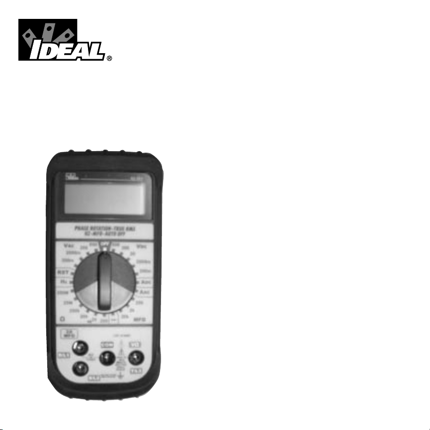
AC Voltage (VAC)
Function Range Resolution Accuracy
AC Voltage 200.0 mV .1 mV
2000 mV 1 mV
200.0 V .1V
600 V 1 V
To Measure AC Voltage:
1. Plug the test leads into the meter inputs as indicated in the
above diagram.
2. Select the proper range to be used within the VAC Function.
3. Connect the meter in parallel with the load or circuit.
4. Measure AC voltage.
VAC
PHASE ROTATI
HZ-MFD-A
2000m
RST
200m
200
600
Black
Red
±(2.0% + 4)
50 to 500Hz
all ranges
PHASE ROTATION-TRUE RMS
HZ-MFD-AUTO OFF
600600
VAC
2000m
200m
RST
Hz
200M
20M
200k
2A
MFD
R/L1
VDC
200
200
20
2000m
200m
ADC
AAC
200
2k
20k
20k
2k
200
MFD
CAT. LLL 600V
COM
V
!
MAX
2A
600V
FUSED
MAX
350V/15
SEC FOR
200mV
RANGE
Page 3
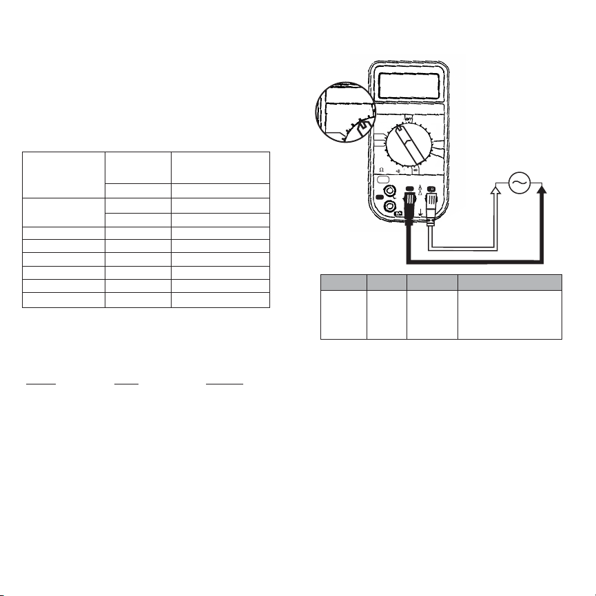
DC Voltage (VDC)
Function Range Resolution Accuracy
DC Voltage 200.0 mV .1 mV
2000 mV 1 mV
20.00 V .01 V
200.0 V .1 V
600 V 1 V
To Measure DC Voltage:
Do not attempt to measure voltage in circuits capable of delivering
more than 600V.
1. Plug the leads into meter inputs as indicated in the
diagram above.
2. Select the proper range to be used within the VDC Function.
3. Connect the meter in parallel with the load or circuit.
4. Measure DC voltage.
Page 5
Page 6
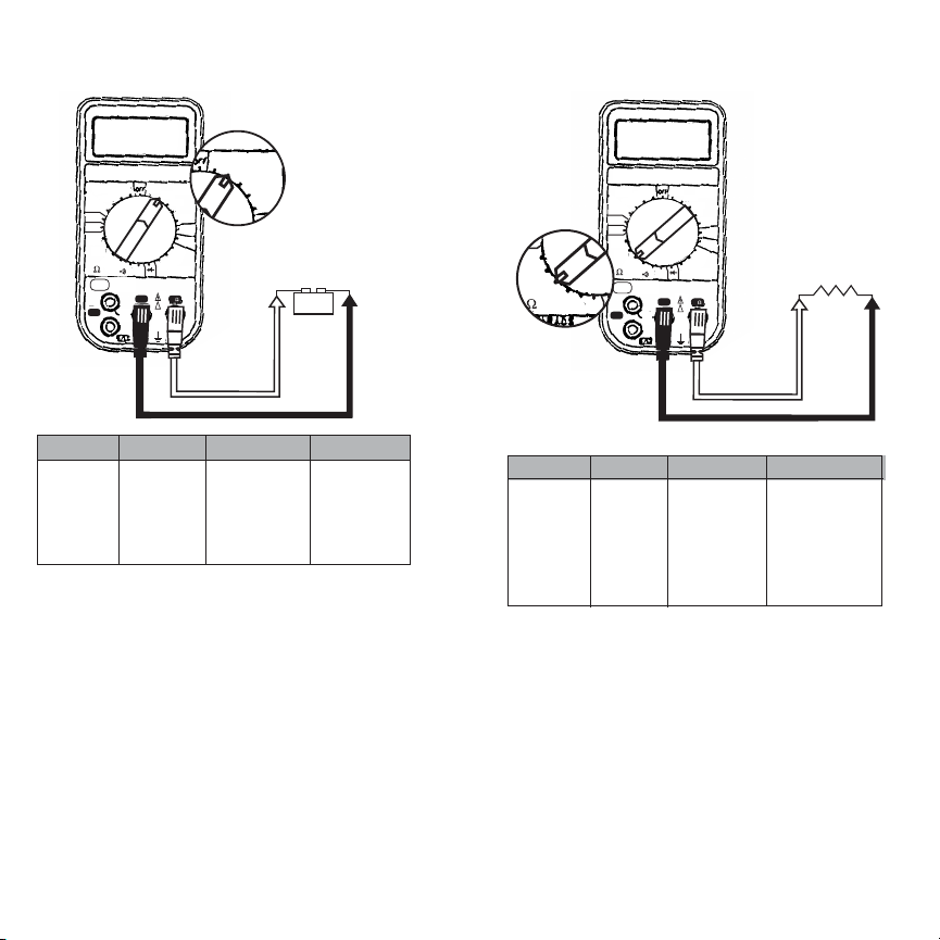
Resistance (Ohms)
Function Range Resolution Accuracy
Resistance 200.0Ω .1Ω ±(1.5% + 4)
2.000kΩ .001kΩ ±(1.5% + 4)
20.00kΩ .01kΩ ±(1.5% + 4)
200.0kΩ .1kΩ ±(1.5% + 4)
20.00MΩ .01MΩ ±(2.5% + 4)
200.0MΩ .1 MΩ ± (5.0% +20)
To Measure Resistance:
Resistance is measured in Ohms.
1. Turn the power off to the circuit or device that is to be measured and discharge all capacitors before attempting a measurement.
2. Plug the red test lead into the “V-
Ω” meter input.
3. Plug the black test lead into the “Com” meter input.
4. Select the proper range within the Ω function of the tester.
VDC
ADC
2000m
20
200
600
Black
Red
20M
20k
200k
2k
Hz
200M
200
Black
Red
± (1.2% +1)
all ranges
PHASE ROTATION-TRUE RMS
HZ-MFD-AUTO OFF
600
600
VAC
2000m
200m
RST
Hz
200M
20M
200k
2A
MFD
R/L1
VDC
200
200
20
2000m
ADC
200
2k
20k
20k
2k
200
MFD
CAT. LLL 600V
COM
V
!
MAX
2A
600V
FUSED
MAX
350V/15
SEC FOR
200mV
RANGE
+
-
PHASE ROTATION-TRUE RMS
HZ-MFD-AUTO OFF
600600
VAC
2000m
200m
RST
Hz
200M
20M
200k
2A
MFD
R/L1
VDC
200
200
20
2000m
200m
ADC
AAC
200
2k
20k
20k
2k
200
MFD
CAT. LLL 600V
COM
V
!
MAX
2A
600V
FUSED
MAX
350V/15
SEC FOR
200mV
RANGE
Page 4

Page 8
Page 7
Resistor Color Code Table
1st 2nd Tolerance
Color Digit Digit Multiplier (Percentage)
Black 0 0 1
Brown 1 1 10
Red 2 2 100
Orange 3 3 1,000
Yellow 4 4 10,000
Green 5 5 100,000
Blue 6 6 1,000,000
Violet 7 7 10,000,000
Gray 8 8 100,000,000
White 9 9 1,000,000,000
Gold +/- 5%
Silver +/- 10%
No Color +/- 20%
Example:
1st color band is blue so the first digit is a 6
2nd color band is red so the second digit is a 2
3rd color band is yellow so multiply 62 x 10,000
4th color band is gold so the tolerance is ±5%
Your Resistor value is 620,000 Ohms (620kΩ) with a tolerance
of ±5%.
5. Measure resistance. If necessary, perform the required multiplication to acquire the actual resistance.
5.1 Range Guide for Ohms (Ω):
200 = Meter indicates actual resistance
2k = Multiply meter display reading by 1,000 to
acquire actual resistance.
20k = Multiply meter display reading by 1,000 to
acquire actual resistance.
200k = Multiply meter display reading by 1,000 to
acquire actual resistance.
2M = Multiply meter display reading by
1,000,000 to acquire actual resistance
200M = Multiply meter display reading by
1,000,000 to acquire actual resistance.
6. The meter displays total resistance through all possi-
ble paths between the probe-tips. These multiple
paths may result in measurements that do not correspond to the ohm value indicated by the resistor
color code.
Determining Resistor Values:
To determine the value of a resistor, use the color bands on the
resistor and the table on the following page.
Blue
Red
Yellow
Gold
Page 5

Page 10Page 9
Diode Verification
Function Range Resolution Accuracy
Diode Test 2 VDC 1 mV ± (3.0% + 1)
Diode Testing:
To ensure a proper functioning diode, the meter will develop a
voltage across the component from a test current. The diode
test function allows measurements of forward and reverse bias
across diodes and transistor junctions.
1. Turn off power to the device or circuit that is being tested
and discharge all capacitors.
2. Plug the leads into the meter inputs as indicated in the
above diagram.
3. Select the diode function on the meter.
4. Check the forward bias of the diode by connecting the red
test probe to the anode (+) and the black test probe to the
cathode (-) of the diode. Read the forward voltage drop on
the meter display.
4.1 A good silicone diode will result in a reading
around 0.7 V.
4.2 A good germanium diode will result in a reading
around 0.3 V.
4.3 A short is indicated by a continuous beep and a
reading of .000 V.
4.4 An open is indicated by an “OL” reading.
5. Check the reverse bias of the diode by reversing the test
lead connections to the diode (red probe to cathode and
black probe to anode).
5.1 A reading of “OL” indicates reverse blocking and a
good diode.
5.2 A reading of .000 V and a continuous beep indicates
high reverse leakage current or a short.
VAC
PHASE ROTATION-TRUE RMS
HZ-MFD-AUTO OFF
VDC
ADC
AAC
2000m
20
20M
20k
200k
2k
2000m
RST
Hz
200m
200M
200
200
600600
200m
200
20k
2k
200
2A
MFD
!
600V
MAX
350V/15
SEC FOR
200mV
RANGE
CAT. LLL 600V
R/L1
COM
V
MAX
2A
FUSED
MFD
Forward Bias
+
-
+
-
Reverse Bias
A
A
2k
200
20k
2k
200
MFD
Black
Red
Page 6

Page 12
Page 11
Continuity Beeper
(beeps at resistance <150Ω)
To Verify Continuity:
A continuity test ensures that all circuit connections are intact.
1. Plug the test leads into the meter inputs as indicated in the
diagram above.
2. Turn the power off to the circuit or device that is to be verified.
3. Select the continuity function on the meter. See
switch position below. The continuity function is located at
the 2kΩ setting.
4. Test for continuity by connecting the meter to the circuit.
5. If the beeper sounds, the circuit is complete.
20k
200k
2k
200
20k
D
Black
Red
Current (AAC and ADC)
Function Range Resolution Accuracy
AC Current 2.000 A .001 A ± (3.0% + 4)
DC Current 2.000 A .001 A 50 to 500Hz
To Measure Current:
Current is measured in amps.
Do not attempt to measure current in circuits capable of delivering greater than 600V.
1. Connect the test leads into the meter inputs as indicated in
the diagram above.
2. Select the AAC or ADC function.
3. Turn the power off.
4. Connect the meter in series with the load or circuit.
5. Turn power on.
6. Measure the Current.
ADC
AAC
200m
20k
2k
200
MFD
Black
Red
PHASE ROTATION-TRUE RMS
HZ-MFD-AUTO OFF
600600
VAC
2000m
200m
RST
Hz
200M
20M
200k
2A
MFD
R/L1
VDC
200
200
20
2000m
200m
ADC
AAC
200
2k
20k
20k
2k
200
MFD
CAT. LLL 600V
COM
V
!
MAX
2A
600V
FUSED
MAX
350V/15
SEC FOR
200mV
RANGE
PHASE ROTATION-TRUE RMS
HZ-MFD-AUTO OFF
600600
VAC
2000m
200m
RST
Hz
200M
20M
200k
2A
MFD
R/L1
VDC
200
200
20
2000m
200m
ADC
AAC
200
2k
20k
20k
2k
200
MFD
CAT. LLL 600V
COM
V
!
MAX
2A
600V
FUSED
MAX
350V/15
SEC FOR
200mV
RANGE
Page 7

Frequency (Hz)
Function Range Resolution Accuracy
Frequency 10 Hz to 100 kHz for AC
10 Hz to 100 Hz for DC* .001 kHz
±(2% + 3 digits)
Sensitivity : 3.5 V rms
Frequency is measured in Hertz:
Do not attempt to measure frequency in circuits capable of
delivering greater than 600V.
1. Plug test leads into the meter inputs as indicated in the
diagram above.
2. Select the Hz function on the meter.
3. Connect the meter in series with the load or circuit.
4. Measure the frequency.
Page 14
Page 13
Phase Rotation (RST)
Function Frequency Range Voltage Range
Phase LCD indicates
Rotation sequence of
Indicator three-phases.
To Determine Phase Rotation (RST):
This test function correctly identifies each of the 3-Phases in a
power panel as R, S, T. Note: The displayed numerical value has
no meaning when performing this procedure. Maximum 3 phase
voltage allowed in this mode is 500 VAC.
1. Turn power off to the circuit that is to be tested.
2. Place the function switch on the meter to “RST.”
3. Plug the test leads into the meter inputs labeled as R, S, T in
the diagram above. Note that test lead colors are insignificant.
4. Attach the three test leads to each of the 3-Phase cables in
any order.
5. Turn the power on.
6. If all three supply lines have power, the meter will indicate a
R, S, T (in the upper left corner).
VAC
20M
2000m
RST
Hz
200m
200M
200
20M
200k
2000m
RST
Hz
200m
200M
Red
Black
*DC Voltage higher than 3.5 V rms
80V to 500V
50 Hz to 500 Hz
PHASE ROTATION-TRUE RMS
HZ-MFD-AUTO OFF
VAC
200
2000m
200m
RST
Hz
200M
20M
200k
20k
2k
200
2A
MFD
COM
MAX
R/L1
2A
FUSED
600600
CAT. LLL 600V
PHASE ROTATION-TRUE RMS
HZ-MFD-AUTO OFF
600600
VAC
VDC
200
20
2000m
200m
ADC
AAC
200
2k
20k
MFD
V
!
600V
MAX
350V/15
SEC FOR
200mV
RANGE
2000m
200m
RST
Hz
200M
20M
200k
2A
MFD
R/L1
R
VDC
200
200
20
2000m
200m
ADC
AAC
200
2k
20k
20k
2k
200
MFD
CAT. LLL 600V
COM
V
!
MAX
2A
600V
FUSED
MAX
350V/15
SEC FOR
200mV
RANGE
T
S
Page 8

Phase Rotation (continued)
7. If the meter indicates “OK” in the display (upper left-hand side),
a. Turn power off to the circuit.
b. Label each phase cable as R, S, or T following the test
lead connections to the labeled meter inputs.
8. If the meter indicates an message in the display (lower
left-hand side), the phase rotation is counter-clockwise.
a. Turn power off to the circuit.
b. Switch any two test lead connections to the phase cables.
c. Turn power on.
d. The meter will now indicate “OK” in the display.
e. Turn the power off.
f. Label each phase cable as R, S, or T following the test
lead connections to the labeled meter inputs.
Capacitance (MFD)
Function Range Resolution Accuracy
Capacitance 200.0 µF .1 µF
2.000 mF .001 mF
20.00 mF .01 mF
To Measure Capacitance:
Capacitance is measured in micro-farads (MFD). Turn off
power and discharge the capacitor before attempting a measurement. The meter measures capacitance by charging the
capacitor with a predetermined current, measuring the resultant
voltage, and then calculating the capacitance.
1. Plug the test leads into the meter inputs as indicated in the
diagram above.
2. Select the proper range to be used within the MFD area on
the meter.
3. Connect the red test lead to the anode (+) of the capacitor,
and the black test lead to the cathode (-) of the capacitor.
4. Measure capacitance.
Page 16
Page 15
ADC
AAC
200m
200
20k
2k
200
MFD
Black
Red
±(4.0% + 10)
all ranges
PHASE ROTATION-TRUE RMS
HZ-MFD-AUTO OFF
600600
VAC
2000m
200m
RST
Hz
200M
20M
200k
2A
MFD
R/L1
VDC
200
200
20
2000m
200m
ADC
AAC
200
2k
20k
20k
2k
200
MFD
CAT. LLL 600V
COM
V
!
MAX
2A
600V
FUSED
MAX
350V/15
SEC FOR
200mV
RANGE
Page 9

Accessories
Optional Clamp Adaptor
To Use Accessories:
Clamp adapters allow multimeters the versatility to measure
large amounts of current safely through a clamphead. IDEAL
clamp adapters convert amps measured into mV signals that the
multimeter can display. Since the clamp adapters convert the
amps measurement into mVAC, the clamp adapter leads must
be inserted into the volts and com inputs and the meter must
be set to the mVAC range. The conversion ratio is one-to-one
(1Amp=1mV). So, when the meter displays 50.0 mV, the clamp
adapter is measuring 50.0 Amps.
For 300 AAC Current Clamp (61-450) with model 61-363:
1. Plug test leads into the meter inputs as indicated in the
diagram above.
2. Remove the probe tips from the end of the leads.
3. Attach the leads to the current clamp (polarity will not affect
reading).
4. a. Select 200 mVAC range for measuring less than 200 Amps.
b. Select 2000 mVAC range for measuring more than 200 Amps.
5. Snap the jaw of the current clamp around one of the current
carrying conductors.
6. Take the reading.
For all other Clamp Adaptors (61-451, 61-334, 61-436):
1. Plug test leads into the meter inputs as indicated in the
diagram above.
2. a. Select 200 mVAC range for measuring less than 200 Amps.
b. Select 2000 mVAC range for measuring more than 200 Amps.
3. Snap the jaw of the current clamp around one of the current
carrying conductors.
4. Take the reading.
General Specifications:
Indicators: Continuity: (<150Ω) indicated by a continuous
“beep” within 100 msec. Low Battery indicator displayed in the
LCD when battery is below operating range. Overrange: “OL”
displayed.
Environmental: Operating temperature 32°F to 122°F, storage
0°F to 140°F with batteries removed, RH<70%.
LCD: 3.5 digits.
Size: 4.0”W x 7.5”H x 2.5”D
Weight: 18 oz. including battery.
Battery life: >200 hours typical (9V NEDA 1604 type, JIS006P,
IEC6F22 battery).
Accessories: Comes with a pair of test leads ground lead with
clip, operator’s manual, and battery.
Overload Protection: 600V for DCV, ACV, and phase indication. 500VAC/500VDC for capacitance, ohms, frequency and
diode test. Current protected by 2A/600V (6.35mm x 25.4mm)
fuse model LA-3893 and 0.1A/250V (5mm x 20mm) fuse model
LA-3898.
User Maintenance
Regular operator maintenance of the multimeter consists of
cleaning case and window, and battery replacement. All other
repairs must be performed by a factory service center or other
qualified instrument service personnel.
Cleaning Case and window
Periodically wipe the case with a damp cloth and detergent,
allow to dry completely before using; do not use abrasives or
solvents.
Battery Replacement
When the multimeter displays the the battery must be
replaced to maintain proper operation.
Page 18
Page 17
VAC
PHASE ROTATION-TRUE RMS
HZ-MFD-AUTO OFF
VDC
ADC
AAC
2000m
20
20M
20k
200k
2k
2000m
RST
Hz
200m
200M
200
200
600600
200m
200
20k
2k
200
2A
MFD
!
600V
MAX
350V/15
SEC FOR
200mV
RANGE
CAT. LLL 600V
R/L1
COM
V
MAX
2A
FUSED
MFD
VAC
2000m
RST
Hz
200m
200
Black
Red
Page 10

WARNING
To prevent electrical shock hazard, turn off the multimeter and disconnect test leads before removing the back cover.
1. Disconnect the test leads and turn the meter off. Remove the
test leads from the front terminals.
2. Position the meter face down. Remove the screws from the
case bottom.
3. Lift the end of the case back until it gently unsnaps.
4. Lift the battery from the case back.
5. Replace battery.
6. Replace the case top. Reinstall screws.
Fuse Replacement
1. Disconnect the test leads and turn the meter off. Remove the
test leads from the front terminals.
2. Position the meter face down. Remove the screws from the
case back.
3. Lift the end of the case back until it gently unsnaps.
4. Remove the fuse by gently prying one end of the fuse loose and
sliding the fuse out of the bracket.
5. Verify continuity across the fuse.
6. If the fuse is good, return to tester.
7. If the fuse is blown, install a new fuse of the same size and rating.
8. Replace the case top. Reinstall screws.
Troubleshooting
The meter has been designed to be accurate, reliable and easy-touse. However, it is possible that you may experience difficulties
during operation. If there appears to be any kind of problem during
use of the multimeter, please perform the following steps to help
determine the source:
1. Review and comply with the operating instructions section of
this instruction manual.
2. Test the battery, replace as necessary.
3. Test the fuses, replace as necessary.
4. Check to see that the Function/Range Switch is in the correct
position for the type of parameter and range of values being
measured, and that the measurement value is within the capability of the multimeter.
5. Inspect the test leads for breaks or cracks, and ensure that the
test leads are inserted fully into the input connectors.
6. If problem persists, meter should be inspected by a qualified
service person.
Page 19
LIFETIME LIMITED WARRANTY
This meter is warranted to the original purchaser against defects
in material or workmanship. During the warranty period, IDEAL
INDUSTRIES, INC. will, at its option, replace or repair the defective unit, subject to verification of the defect or malfunction.
This warranty does not apply to defects resulting from abuse,
neglect, accident, unauthorized repair, alteration, or unreasonable
use of the instrument.
Any implied warranties arising out of the sale of an IDEAL product, including but not limited to implied warranties of merchantability and fitness for a particular purpose, are limited to the
above. The manufacturer shall not be liable for loss of use of the
instrument or other incidental or consequential damages,
expenses, or economic loss, or for any claim or claims for such
damage, expenses, or economic loss.
State laws vary, so the above limitations or exclusions may not
apply to you. This warranty gives you specific legal rights, and
you may also have other rights which vary from state to state.
Page 20
 Loading...