

Page 1

Page 2

2
Systemiser SE - Installation
Systemiser SE:
The condensing system boiler
The Ideal Systemiser SE is a wall mounted, fanned flue condensing system
boiler which serves a home's central heating system. It has been designed to
be 'friendly' to the user, installer and service engineer.
Systemiser SE:
The fit anywhere system boiler
Simple fanned 'go anywhere' flue
The Systemiser SE's flue turret simply rotates through 360° to allow horizontal
outlet in any direction. Options include horizontal flue length extensions or
simple vertical flue kits - and the flue is self-sealing, eliminating the need for
outside assembly - an important benefit in high-rise applications.
Downward or upward connections...
Water and gas connections have been designed to be as simple and fast as
possible. The Ideal Systemiser SE comes complete with a rugged mounting
frame which when fitted with the stand-off brackets can accommodate
downward or upward routed gas, water and electrical connections before the
boiler is fitted.
...and it fits inside a cupboard
Its compact size makes the Systemiser SE ideal for any kitchen. It can be
installed inside a cupboard without any ventilation.
Systemiser SE:
The system boiler you can rely on
The Systemiser SE has been designed and developed with reliability as the
number one priority. But even the finest engineered product may develop a
fault at some stage in its lifetime. To support the Systemiser SE we have
created the Ideal Care Guarantee which sets out our target to repair any fault
next day.
Free Guarantee: 1st Year Ideal Care
The home owner is entitled to 12 months free Ideal Care, which includes both
parts and labour, to restore the boiler to full function. Please encourage the
home owner to complete and return the registration form in their Householder's
pack within 30 days of installation.
Optional Extra Year Cover with Ideal Care
You may wish to offer your own annual service plan or you may wish to advise
the home owner to complete their application form for the appropriate level of
extended Ideal Care - Silver, Gold or Platinum. Full details are available in
the Ideal Care brochure.
Page 3

3
Systemiser SE - Installation
Gas supply 2H
Gas Supply Connection 22mm copper
Flow Connection Central Heating 22mm copper
Return Connection Central Heating 22mm copper
Flue Terminal Diameter 100 mm
Maximum Working Pressure (Sealed Systems) 2.65 bar
Electrical Supply / Power consumption 230 V ~ 50 Hz. / 126 W
Fuse Rating External : 3A Internal : F2A
Water content Central Heating 2.2 litre
Dry Weight 46.5 Kg
Maximum Installation Weight 38.5 Kg
Boiler Casing Size Height 800 mm
Width 450 mm
Depth 300 mm
Table 1 - General Data
GENERAL
Table 2 - Performance Data - Central Heating
Min. Max.
Boiler Input :
Nett CV kW 10.1 25.1
Btu/h 34 500 85 700
Gross CV kW 11.2 27.9
Btu/h 38 200 95 200
Gas Consumption l/s 0.29 0.72
ft
3
/h 36.8 91.5
Boiler Output :
70
o
C Mean Water Temp kW 9.6 24.0
Btu/h 32 800 81 900
40 oC Mean Water Temp kW 10.9 25.7
Btu/h 37 200 87 700
Burner Setting Pressure mbar 2.0 13.0
(HOT) in. w.g. 0.8 5.2
Seasonal Efficiency
(SEDBUK) * [88.4]%
CAUTION.
To avoid the possibility of injury during the installation, servicing or cleaning of
this appliance, care should be taken when handling edges of sheet steel components.
KEY TO SYMBOLS
IE = Ireland (Countries of
GB = United Kingdom destination)
PMS = Maximum operating pressure of water
C13 = A room sealed appliance designed for connection via
ducts to a horizontal terminal, which admits fresh air to
the burner and discharges the products of combustion
to the outside through orifices which, in this case, are
concentric. The fan is up stream of the combustion
chamber.
I
2H
= An appliance designed for use on 2nd Family gas,
Group H only.
Note. Gas consumption is calculated using a calorific value of
38.7 MJ/m
3
(1038 Btu/ft3) gross or 34.9 MJ/m3 (935 Btu/ft3) nett
To obtain the gas consumption at a different calorific value:
a. FOR L/S - divide the gross heat input (kW) by the gross
C.V. of the gas (MJ/m
3
)
b. FOR FT3/H - divide the gross heat input (Btu/h) by the gross
C.V. of the gas (Btu/ft3)
*The value is used in the UK Government's Standard
Assessment Procedure (SAP) for energy rating of dwellings.
The test data from which it has been calculated have been
certified by Gastech NV0061.
Page 4

4
Systemiser SE - Installation
CONTENTS
INTRODUCTION
The Systemiser SE is a wall mounted, low water content,
balanced flue, condensing system boiler.
Note. Due to the high efficiency of the boiler a plume of
water vapour will form at the terminal during operation.
Central Heating (CH) output is fully modulating between
9.6 kW (32 800 Btu/h) minimum and 24 kW (81 900 Btu/
h) maximum.
The boiler is supplied fully assembled with circulating
pump, pressure gauge, safety valve and central heating
(CH) expansion vessel.
A variable CH temperature control is fitted.
The boiler casing is of white painted mild steel with a
dropdown controls door.
The boiler controls are located behind the controls door.
The heat exchanger is of aluminium.
The boiler is suitable for connection to fully pumped,
sealed water systems ONLY. Adequate arrangements for
completely draining the system, by provision of drain
cocks, MUST be provided in the installation pipework.
OPTIONAL EXTRA KITS
Extension Flue Kit - Pack D
Roof Flue Kit - for vertical flue connection
Powered Vertical - for extended vertical flue connection
Flue
Flue Elbow Kits - 90 degree
- 45 degree (2 per box)
Siphon Kit - Pack S
Refer to the separate fitting instructions supplied with
each kit.
Systemiser SE (natural gas only) .......... G.C. Appliance No. 41 349 70
Gastec Certification ............................. P.I. No. 0063 AS 3355 Destination Countries: GB and IE
Air Supply ........................................................................ 6
Boiler Clearances ............................................................ 9
Boiler Exploded Diagram ............................................. 12
Commissioning and Testing ........................................ 33
Condensate Drain ......................................................... 11
Electrical Connections ................................................. 29
Electrical Supply ............................................................. 9
Fault Finding ................................................................. 54
Flow Wiring Diagram .................................................... 30
Flue Extensions ............................................................ 26
Flue Installation ............................................................. 15
Flue Lengths & Types ................................................... 14
Gas Safety ........................................................................ 6
Gas Supply ...................................................................... 7
General Data .................................................................... 3
Installation ..................................................................... 12
Mandatory Requirements ............................................... 6
Safety ............................................................................... 6
Sealed System Requirements ...................................... 10
Servicing ........................................................................ 39
Short List of Parts ......................................................... 56
Water and Systems ......................................................... 7
Water Connections ......................................................... 8
Water Treatment .............................................................. 8
Wiring Diagrams .................................................... 30 - 33
NOTE TO THE INSTALLER:
LEAVE THESE
INSTRUCTIONS ADJACENT TO THE GAS METER.
ALSO COMPLETE THE BENCHMARK LOG BOOK
AND GIVE THIS TO THE CUSTOMER.
Page 5

5
Systemiser SE - Installation
GENERAL
OPERATION
When there is a call for CH, the heating system is
supplied at the selected temperature of between 40 oC
and 82 oC,
Refer also to Frame 1- 'Boiler Water Circuit Diagram'.
The boiler features a comprehensive diagnostic system
which gives detailed information on the boiler status when
operating, and performance of key components to aid in
commissioning and fault finding.
1
BOILER WATER CIRCUIT DIAGRAM
Page 6

6
Systemiser SE - Installation
GENERAL
GAS SAFETY
Current Gas Safety (Installation and Use) Regulations,
or rules in force.
It is law that all gas appliances are installed and serviced by a
CORGI registered installer (identified by
) in accordance
with the above regulations. Failure to install appliances
correctly could lead to prosecution. It is in your own interest,
and that of safety, to ensure the law is complied with.
The installation of the boiler MUST also be in accordance with
the latest I.E.E (BS.7671) Wiring Regulations, local building
regulations, bye-laws of the local water authority, the building
regulations and the Building Standards (Scotland) and any
relevant requirements of the local authority.
Detailed recommendations are contained in the following British
Standard Codes of Practice:
BS. 5440:1 Flues (for gas appliances of rated input not
exceeding 60 kW).
BS. 5440:2 Ventilation (for gas appliances of rated input not
exceeding 60 kW).
BS. 5449 Forced circulation hot water systems.
BS. 5546 Installation of gas hot water supplies for domestic
purposes (2nd Family Gases)
BS. 6700 Design, installation testing and maintenance of
services supplying hot water for domestic use.
BS. 6798 Installation of gas fired hot water boilers of rated
input not exceeding 60 kW.
BS. 6891 Low pressure installation pipes.
Health & Safety Document No. 635.
The Electricity at Work Regulations, 1989.
The manufacturer’s notes must NOT be taken, in any way, as
overriding statutory obligations.
SAFE HANDLING OF SUBSTANCES.
Care should be taken when handling the boiler insulation
panels, which can cause irritation to the skin. No asbestos,
mercury or CFCs are included in any part of the boiler.
IMPORTANT. These appliances are CE certificated for safety
and performance. It is, therefore, important that no external
control devices, e.g. flue dampers, economisers etc., are directly
connected to these appliances unless covered by these
Installation and Servicing Instructions or as otherwise
recommended by Caradon Plumbing Limited in writing. If in
doubt please enquire.
Any direct connection of a control device not approved by
Caradon Plumbing Limited could invalidate the certification
and the normal appliance warranty. It could also infringe the
Gas Safety Regulations and the above regulations.
LOCATION OF BOILER AND FLUE OUTLET
The boiler must be installed on a flat and vertical wall, capable
of adequately supporting the weight of the boiler and any
ancillary equipment.
The boiler may be fitted on a combustible wall. Insulation
between the wall and the boiler is not necessary, unless
required by the local authority.
The boiler must not be fitted outside.
Timber Framed Buildings
If the boiler is to be fitted in a timber framed building it should
be fitted in accordance with the Institute of Gas Engineering
document IGE/UP/7:1998.
Bathroom Installations
The boiler may be installed in any room or internal space,
although particular attention is drawn to the requirements of the
current I.E.E. (BS.7671) Wiring Regulations and, in Scotland,
the electrical provisions of the building regulations applicable in
Scotland with respect to the installation of the boiler in a room
or internal space containing a bath or shower.
Where a room sealed appliance is installed in a room
containing a bath or shower then the appliance and any
electrical switch or appliance control utilising mains electricity
should be so situated that it cannot be touched by a person
using the bath or shower.
Note. It is not permissible to install a mains socket in a
bathroom.
Where installation will be in an unusual location, special
procedures may be necessary and BS 6798 gives detailed
guidance on this aspect.
Compartment Installations
A compartment used to enclose the boiler should be designed
and constructed specially for this purpose.
An existing cupboard or compartment may be used, provided
that it is modified for the purpose.
In both cases, details of essential features of cupboard /
compartment design, including airing cupboard installation, are
to conform to the following:
z BS.6798.
z The position selected for installation MUST allow adequate
space for servicing in front of the boiler. Ventilation of the
compartment is not necessary.
z For the minimum clearances required for safety and
subsequent service see the wall mounting template and
Frame 3. In addition, sufficient space may be required to
allow lifting access to the wall mounting plate.
AIR SUPPLY
It is NOT necessary to have a purpose-provided air vent in the
room or internal space in which the boiler is installed. Neither is
it necessary to ventilate a cupboard or compartment in which
the boiler is installed, due to the low surface temperatures of the
boiler casing during operation; therefore the requirements of BS
6798, Clause 12, and BS 5440:2 may be disregarded.
Page 7

7
Systemiser SE - Installation
GENERAL
5. Where the lowest part of the terminal is fitted less than 2m
(6'6") above a balcony, above ground or above a flat roof to
which people have access then the terminal MUST be
protected by a purpose designed guard. The minimum
spacing in Table 3, Nos. 2, 3, 4, 5 and 6 would be 75mm, in
order to allow a terminal guard to be fitted.
Terminals guards are available from boiler suppliers - ask
for Tower Flue Guard, Model K1. In case of difficulty seek
advice from:
Tower Flue Components Ltd.,
Vale Rise, Tonbridge, Kent TN9 1TB
Telephone No. 01732 351 555
Ensure that the guard is fitted centrally.
6. Where the terminal is fitted within 850mm (34") of a plastic
or painted gutter or 450mm (18") of painted eaves then an
aluminium shield at least 750mm (30") long should be fitted
to the underside of the gutter or painted surface fitted
centrally above the flue.
7. The air inlet/products outlet duct and the terminal of the
boiler MUST NOT be closer than 25mm (1") to combustible
material. Detailed recommendations on the protection of
combustible material are given in BS. 5440: 1990.
8. Where it is essential that the terminal wall plate is fitted, i.e.
wall thicknesses over 610mm (24") or with an inaccurately
cut hole, the minimum spacing in Table 3, Nos. 2, 3, 4, 5
and 6 would be 60mm (2.4") in order to allow the terminal
wall plate to be fitted.
IMPORTANT. It is the responsibility of the installer to ensure, in
practice, that products of combustion discharging from the
terminal cannot re-enter the building or any other adjacent
building through ventilators, windows, doors, other sources of
natural air infiltration, or forced ventilation / air conditioning.
If this should occur the appliance MUST be turned OFF, labelled
as 'unsafe' until corrective action can be taken.
FLUE LENGTHS
The flue assembly can be adapted to accommodate flue
lengths up to 3 metres. Refer to Frame 10.
WATER CIRCULATION SYSTEM
The boiler is designed for connection to pressurised, fully
pumped, sealed water central heating systems ONLY.
The central heating system should be installed and
commissioned in accordance with BS. 6798 and, in addition, for
smallbore and microbore systems BS. 5449.
The domestic hot water system should be in accordance with
BS. 5546 and BS. 6700.
Copper tubing to BS 2871:1 is recommended for water carrying
pipework and MUST be used for pipework carrying potable
water.
Any soldered joints on potable water pipework MUST NOT be
made with solder containing lead.
GAS SUPPLY
The local gas supplier should be consulted, at the installation
planning stage, in order to establish the availability of an adequate
supply of gas. An existing service pipe must NOT be used without
prior consultation with the local gas supplier.
A gas meter can only be connected by the local gas supplier or by
a registered CORGI installer.
Check that the appliance is suitable for the proposed gas supply.
A working gas pressure of 20 mbar MUST be available at the
boiler inlet.
IMPORTANT.
Installation pipes MUST be fitted in accordance with BS. 6891.
Pipework from the meter to the boiler MUST be 22mm O.D.
The complete installation MUST be tested for gas soundness and
purged as described in the above code.
FLUE INSTALLATION
The flue must be installed in accordance with the
recommendations of BS. 5440: Part 1.
The following notes are intended for general guidance:
1. The boiler MUST be installed so that the terminal is
exposed to external air.
2. It is important that the position of the terminal allows the
free passage of air across it at all times.
3. Minimum acceptable spacing from the terminal to
obstructions and ventilation openings are specified in
Table 3.
4. Pluming will occur at the terminal, so where possible,
terminal positions where this could cause a nuisance
should be avoided.
Terminal Position
Minimum Spacing
1. Directly below or alongside an
opening window, air vent or other
ventilation opening 300 mm (12")
2. Below guttering, drain pipes or soil
pipes 25 mm ( 1")
3. Below eaves 25 mm ( 1")
4. Below balconies or a car port roof 25 mm ( 1")
5. From vertical drain pipes or soil pipes 25 mm ( 1")
6. From internal or external corners 25 mm ( 1")
7. Above adjacent ground, roof or
balcony level 300 mm (12")
8. From a surface facing the terminal 600 mm (24")
9. From a terminal facing a terminal 1200 mm (48")
10. From an opening in a car port
(e.g. door or window) into dwelling 1200 mm (48")
11. Vertically from a terminal on the
same wall 1500 mm (60")
12. Horizontally from a terminal on the wall 300 mm (12")
Table 3 - Balanced flue terminal position
N.B. These clearances are for horizontal flue only.
Refer to supplementary manual for roof flue kits.
Note (Positions 2-6) : Due to the terminal design, installation is
possible with clearances less than those specified in BS 5440,
Part 1.
Page 8

8
Systemiser SE - Installation
GENERAL
Ancillary pipework not forming part of the useful heating
surface should be lagged to prevent heat loss and any
possible freezing - particularly where pipes run through roof
spaces or ventilated underfloor spaces.
Draining taps should be at least 1/2" BSP nominal size and be
in accordance with BS 2879.
Maximum recommended system hydraulic losses are given in
within Frame 4.
WATER TREATMENT
The Systemiser SE has an aluminium heat exchanger. If water
treatment is used Caradon Plumbing Limited recommend only
the of Fernox-Copal or Sentinel X100 water treatment products,
which must be used in accordance with the manufacturers'
instructions.
For further information contact either:
Fernox Manufacturing Co. Ltd
Tandem House
Marlowe Way
Croydon, Surrey
CRO 4XS
Tel: 0870 5601 5000
or
Betz Dearborn Ltd.
Widnes
Cheshire
Tel. 0151 424 5351
IMPORTANT.
The application of any other treatment to this product will
render the guarantee of Caradon Plumbing Limited invalid.
The CH flow and return pipe
connections are located at the
bottom of the boiler.
2
BOILER WATER CONNECTIONS
Notes.
1. It is most important that the correct concentration of the
water treatment product is maintained in accordance with
the manufacturers' instruction.
2. If the boiler is installed in an existing system any unsuitable
additives must be removed by thorough cleansing. BS.
7593:1992 details the steps necessary to clean a domestic
central heating system.
3. In hard water areas, treatment to prevent limescale may be
necessary. However, the use of artificially softened water is
not permitted.
4. Under no circumstances should the boiler be fired before
the system has been thoroughly flushed.
THERMOSTATIC RADIATOR VALVES (TRV)
Caradon Plumbing Limited recommend that heating systems
utilising full thermostatic radiator valve control of temperature in
individual rooms should also be fitted with a room thermostat
controlling the temperature in a space served by radiators not
fitted with such a valve as stated in BS. 5449.
When thermostatic radiator valves are used a bypass should
be fitted, ensuring it is at least 3m from the boiler. The bypass
should have at least 6m of flow and return pipe of a minimum
22mm diameter.
For further information refer to the 'Good Practice Guide 143', a
publication of the Energy Efficiency Office, available from the
Building Research Establishment, Garston, Watford WD2 7JR.
Tel: 01923 664258.
Page 9

9
Systemiser SE - Installation
GENERAL
ELECTRICAL SUPPLY
WARNING. This appliance must be efficiently earthed.
Wiring external to the appliance MUST be in accordance with
the current I.E.E. (BS.7671) Wiring Regulations and any local
regulations which apply.
The point of connection to the mains should be readily
accessible and adjacent to the boiler, except for bathroom
installations where the point of connection to the mains MUST
be situated outside of the bathroom.
Note. Where a room sealed appliance is installed in a room
containing a bath or shower then the appliance and any
electrical switch or appliance control utilising mains electricity
should be so situated that it cannot be touched by a person
using the bath or shower.
The following minimum clearances must be
maintained for operation and servicing.
Additional space will be required for installation,
depending upon site conditions.
Front clearance: 450 mm from the front of the
boiler casing. The minimum front clearance
when built in to a cupboard is 5mm.
3
BOILER CLEARANCES
For side outlet flues:
Raise the centre line of the hole in
the wall by 5mm +4mm/100mm of
flue length
Dimension y
Boiler only with stand-
off brackets
139mm 219mm
(5 (
7/16") (8 5/8")
Page 10

10
Systemiser SE - Installation
4
SYSTEM REQUIREMENTS - Central Heating
GENERAL
Notes
a. The method of filling, refilling, topping up or flushing
sealed primary hot water circuits from the mains via a
temporary hose connection is only allowed if acceptable
to the local water authority.
b. Antifreeze fluid, corrosion and scale inhibitor fluids
suitable for use with boilers having aluminium heat
exchangers may be used in the central heating system.
Advice should be sought from a local water treatment
company.
General
1. The installation must comply with all relevant national and
local regulations.
2. The installation should be designed to work with flow
temperatures of up to 82
0
C.
3. All components of the system must be suitable for a
working pressure of 3 bar and temperature of 110
0
C.
Extra care should be taken in making all connections so
that the risk of leakage is minimised.
The following components are incorporated within the
appliance:
a. Circulating pump.
b. Safety valve, with a non-adjustable pre-set lift pressure
of 3 bar.
c. Pressure gauge, covering a range of 0 to 6 bar.
d. A 9-litre expansion vessel, with an initial charge
pressure of 0.75 bar.
4. 'Make-up' Water. Provision must be made for replacing
water loss from the system, either :
a. From a manually filled 'make-up' vessel with a readily
visible water level. The vessel should be mounted at
least 150mm above the highest point of the system
and be connected through a non-return valve to the
system, fitted at least 150mm below the 'make-up'
vessel on the return side of the radiators.
or
Safety valve setting bar 3.0
Vessel charge pressure bar 0.5 to 0.75
System pre-charge pressure bar None 1.0
System volume Expansion vessel
(litres) volume (litres)
25 1.6 1.8
50 3.1 3.7
75 4.7 5.5
100 6.3 7.4
125 7.8 9.2
150 9.4 11.0
175 10.9 12.9
190 11.9 14.0
200 12.5 14.7
250 15.6 18.4
300 18.8 22.1
For other system volumes
multiply by the factor across 0.063 0.074
b. Where access to a 'make-up' vessel would be difficult,
by pre-pressurisation of the system.
The maximum cold water capacity of the
system should not exceed 143 litres, if not
pressurized. However, if the system is to be
pressurized, the efficiency of the expansion
vessel will be reduced and a larger vessel (or
smaller system volume) may be necessary. If
the capacity of the vessel is not considered
sufficient for this, or for any other reason, an
additional vessel MUST be installed on the
return to the boiler.
Guidance on vessel sizing is given above.
Page 11

11
Systemiser SE - Installation
5
SYSTEM REQUIREMENTS - CH (continued)
GENERAL
5. Filling. The system may be filled by one of the following
methods:
a. Through a temporary hose connection from a 'draw-off'
tap, supplied from a service pipe under mains pressure.
Where the mains pressure is excessive, a pressure
reducing valve must be used to facilitate filling.
i. Thoroughly flush out the whole system with cold
water.
ii. Fill and vent the system until the pressure gauge
registers 1.5 bar, and examine for leaks.
iii. Check the operation of the safety valve by raising
the water pressure until the valve lifts. This should
occur within 0.3 bar of the pre-set lift pressure.
iv. Release water from the system until the minimum
system design pressure is reached; 1.0 bar if the
system is to be pre-pressurised.
Refer to Frame 33.
Refer also to the British Gas document: 'Guidance Notes for
the Installation of Domestic Gas Condensing Boilers'
(1989)
A condensate drain is provided on the boiler. This drain must
be connected to a drainage point on site.
All pipework and fittings in the condensate drainage system
MUST be made of PLASTIC - no other materials may be used.
The boiler does not normally need a bypass but at least some
radiators on the heating circuit, of load of at least 60% of the
boiler output, at minimum rate i.e. 60% of 10.1 kW (34 500
Btu's) equal 6kW (21 000 Btu's) must be provided with twin
lockshield valves so that this minimum heating load is always
available.
Note.
Systems incorporating zone valves which could completely cut
off the flow through the system, must be wired such that the
boiler will not fire or continue to fire when this occurs.
6
SYSTEM BALANCING
BALANCING
1. Set the programmer to ON.
Close the manual or thermostatic valves on all
radiators, leaving the twin lockshield valves (on the
radiators referred to above) in the OPEN position.
Turn up the room thermostat and adjust these
lockshield valves to give boiler flow and return
temperatures not more than 15
o
C apart.
These valves should now be left as set.
2. Open all manual or thermostatic radiator valves and
adjust the lockshield valves on the remaining
radiators, to give around 11 oC temperature drop at
each radiator.
3. Adjust the room thermostat and programmer to
NORMAL settings.
The drain outlet on the boiler is standard 22mm overflow
pipe.
IMPORTANT
External pipe runs must be insulated to prevent possible
freezing.
A Siphon Kit is available see instructions supplied with the
kit.
7
CONDENSATE DRAIN
Water Flow Rate and Pressure Loss
Boiler size 24
System Load 24 kW
Water Flow Rate 0.51 l/s
Temperature Differential 11
O
C
Pressure available 29 kPa
for system 2.9 m
Page 12

12
Systemiser SE - Installation
8
BOILER ASSEMBLY - Exploded View
INSTALLATION
INSTALLATION
Legend
1. Burner
3. Gas valve
4. Detection electrode
5. Ignition electrodes
13. Fan
26. Boiler flow pipe
27. System flow pipe
30. Gas inlet pipe
35. Heat exchanger
48. Prepiping frame
16. Expansion vessel
17. Pump
18. Automatic air vent
22. System return pipe
25. Pump outlet pipe
50. Control panel
72. Gas injection pipe
Page 13

13
Systemiser SE - Installation
INSTALLATION
INSTALLATION
Unpack and check the pack contents
9
UNPACKING
HARDWARE PACK
M6 x 10 Pozi pan screw - 4 off
M6 shakeproof washer - 4 off
No. 14 x 50mm slotted rd. hd. screw - 4 off
Wall plug (brown) - 4 off
Condensate drain adaptor - 1 off
1/2" sealing washer - 3 off
3/4" sealing washer - 3 off
15mm olive - 3 off
22mm olive - 2 off
Turret seal - 1 off
PACK CONTENTS
z Complete boiler assembly
z Hardware Pack (listed separately below)
z Wall mounting plate
z Wall mounting template
z These Installation and Servicing Instructions
z User's Instructions
z Stand-off brackets (optional use) (1 pair)
z Concealment panels (optional use) (1 pair)
Stand-off brackets
Concealment panels
The boiler
Piping frame
15mm compression nut - 2 off
22mm compression nut - 2 off
15mm pipe connector - 2 off
22mm - 15mm reducing coupling - 1 off
1/2" - 15mm adaptor - 1 off
15mm street elbow - 1 off
22mm street elbow - 2 off
Pressure relief valve outlet pipe - 1 off
Pressure relief valve nut - 1 off
3-way plug - 1 off
Pack B Contents
No. 8 x 8mm self tapping screws - 2 off.
Flue support cutting aid - 1 off.
No.10 x 2" screws - 4 off.
Rawlplugs - 4 off.
Page 14
14
Systemiser SE - Installation
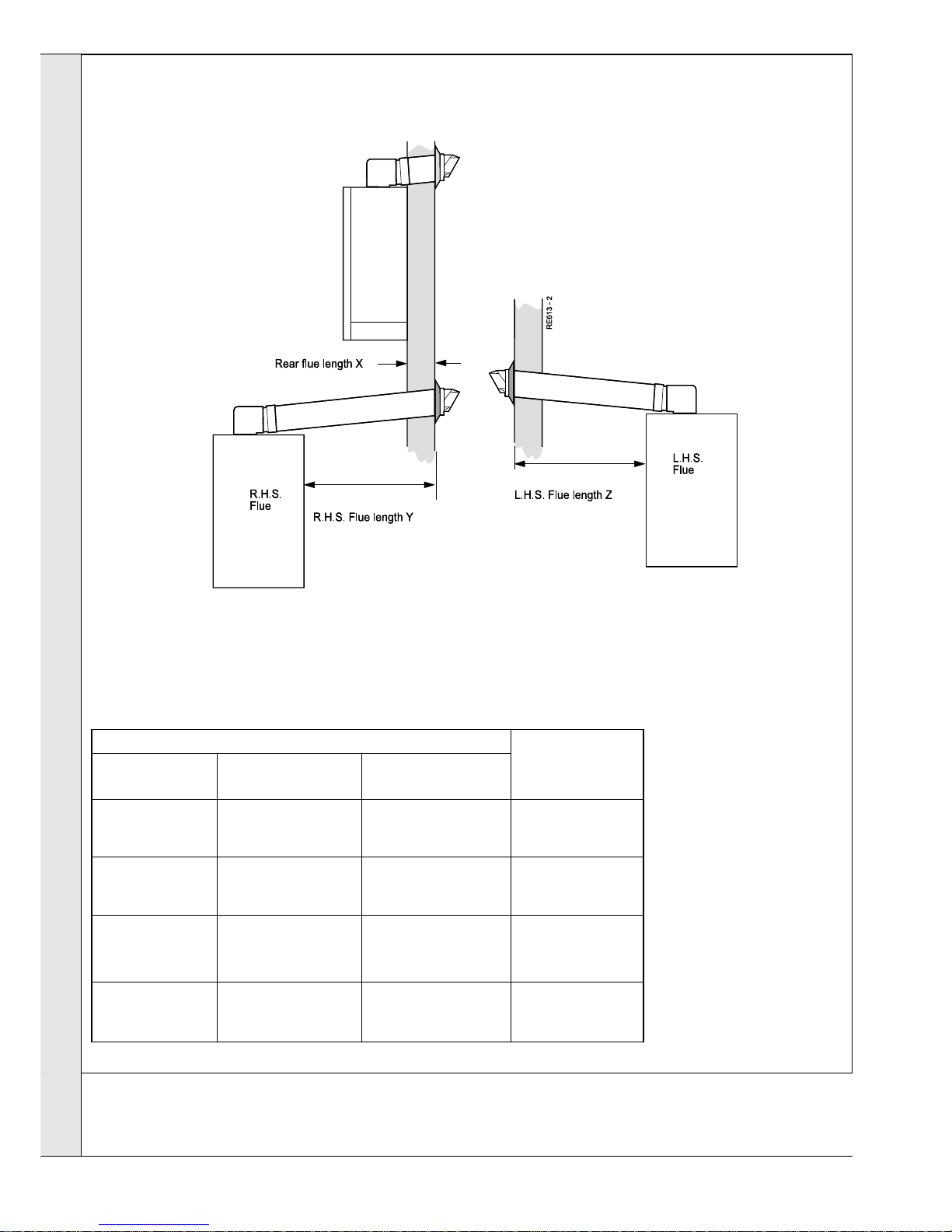
Flue length dimension Flue
Rear flue Right hand side Left hand side packs
dimn. X flue dimn. Y flue dimn. Z required
114 - 580 mm 114 - 410 mm 114 - 540 mm Pack B - 1 off
(4
1/2" - 22 3/4") (4 1/2" - 16" ) (4 1/2" - 21 1/4" )
580 - 1530 mm 410 - 1360 mm 540 - 1490 mm Pack B - 1 off &
(22 3/4" - 60 1/4") (16" - 53 1/2") (21 1/4" - 58 1/2") Pack D - 1 off
1530 - 2480 mm 1360 - 2310 mm 1490 - 2440 mm Pack B - 1 off &
(60
1/4" - 97 3/4") (53 1/2" - 90 3/4") (58 1/2" - 96") Pack D - 2 off
2480 - 3000 mm 2310 - 3000 mm 2440 - 3000 mm Pack B - 1 off &
(97 3/4" - 118") (90 3/4" - 118") ( 96" - 118") Pack D - 3 off
INSTALLATION
INSTALLATION
For REAR outlet flue Go to Frame 11
For SIDE outlet flue Go to Frame 21
10
DETERMINING THE FLUE LENGTH AND FLUE PACKS REQUIRED
Dimension X - Wall thickness
Dimension Y - Wall thickness plus
boiler spacing
(RHS)
Dimension Z - Wall thickness plus
boiler spacing
(LHS)
Calculate the total length of flue by the following:
Rear flue length = Dim. X + 40mm (1
5/8")
RHS flue length = Dim. Y + 188mm (7 3/8")
LHS flue length = Dim. Z + 61mm (2
3/8
")
Note.
These figures include the length of flue entering the
flue turret socket.
Table. Flue pack requirements
FLUE KITS
Pack B
supplied as standard.
Pack D
optional extension kit for
side flue or rear flue
outlet 1000 mm long.
Refer to 'Flue Extension
Ducts'
Vertical Flue
see optional extras.
IMPORTANT.
The boiler MUST be installed in a vertical position.
Note. The flue duct MUST be inclined at 2.5o to the
horizontal to allow condensate to drain back into the
boiler and out through the condensate drain.
Page 15

15
Systemiser SE - Installation
INSTALLATION
REAR FLUE OUTLET
11
REAR FLUE ASSEMBLY - Exploded View
1. An optional flue duct extension kit is required
for rear flue lengths greater than 580mm
(22 3/4"). Refer to Frame 11.
2. When cutting the ducts always use the
cardboard support cutting aid provided.
LEGEND
1. Terminal.
2. Weather seal.
3. Duct assembly.
4. No. 8 x 8 self-tapping screw.
12
WALL MOUNTING TEMPLATE
IMPORTANT.
For direct mounting (piping frame on wall) choose one black
circle in each group.
If using the stand-off brackets choose one dotted circle in
each group. Care MUST be taken to ensure the correct
holes are drilled.
1. Tape the template into the selected position.
2. Ensure squareness by hanging a plumbline as shown.
3. Mark onto the wall the following:
a. The 4 wall mounting plate screw positions.
b. The position of the flue duct.
Mark the centre of the hole as well as the
circumference.
4. Remove the template from the wall.
5. Flue Turret.
6. M5 x 10 pozi screw.
7. Turret Clamp.
8. Turret seal.
Page 16

16
Systemiser SE - Installation
INSTALLATION
REAR FLUE OUTLET
13
PREPARING THE WALL
Note. If the terminal is to be sited within 25-
40mm of a corner or vertical pipe then the hole
MUST be accurately cut and the rubber
weather seal trimmed around the groove
provided.
The terminal wall plate need not be fitted.
1. Cut the flue hole (preferably with a 5" core
boring tool), ensuring that the hole is
square to the wall.
Both wall faces immediately around the
cut hole should be flat.
2. Drill 4 holes with a 7mm (
1/4") masonry
drill and insert the plastic plugs provided,
for the wall piping frame.
WARNING. Ensure that, during the cutting operation, masonry falling
outside of the building does not cause damage or personal injury.
14
FITTING THE PIPING FRAME
Fit the wall mounting frame either:
a. Directly to the wall
zz
zz
z Insert wall plugs.
zz
zz
z Put the screws into the wall plugs and leave
10mm proud
zz
zz
z Hang the frame onto the screws and tighten up.
or
b. Use stand-off brackets
(To allow pipework to be taken upwards).
zz
zz
z Insert wall plugs.
zz
zz
z Put the screws into the wall plugs and leave 10mm
proud.
zz
zz
z Fasten each bracket to the frame with the 6mm screws
and washers provided.
zz
zz
z Hang the brackets and frame onto the screws and
tighten up.
Note. If the clearances above and below the boiler are
less than the length of the pipes it will be necessary to
position the pipes behind the wall mounting plate
BEFORE the plate is screwed to the wall.
Page 17

17
Systemiser SE - Installation
INSTALLATION
15
WATER CONNECTIONS
REAR FLUE OUTLET
Extend a gas supply pipe of not less than 22mm O.D.
copper or 3/4" BSP iron to the boiler.
A working gas pressure of 20mb (8" w.g) must be
available at the boiler inlet, with the boiler firing at full
rate.
16
GAS CONNECTION
Bottom and top connections
1. Solder the 1/2" connector, street elbow, straight pipe and
reducing coupling together.
2. Remove the gas cock bracket complete with gas cock.
3. Screw the connector into the gas cock in the correct
orientation.
4. Screw the complete assembly back onto the mounting
frame.
For top connections: Reverse elbow
Note.
1. Do not subject any of the isolating valves to heat as the seals may
be damaged.
2. In areas where the mains water pressure is known to be high
(greater than 10 bar) it is recommended that a water governor is
fitted on the cold inlet supply to the boiler.
CH CONNECTIONS TANK CONNECTIONS
Top Connection
Page 18

18
Systemiser SE - Installation
INSTALLATION
2. Undo the 2 screws and remove the
boiler bottom panel.
3. Lift the boiler on to the wall, locating the
CH flow and return pipes and gas pipe
to the service pipes.
Tighten all pipe connections.
17
MOUNTING THE BOILER
REAR FLUE OUTLET
1. Remove the boiler casing:
a. Undo the securing screw.
b. Disengage the casing from the back panel and lift it
from the boiler.
18
CUTTING THE FLUE Rear Flue Length of 114 to 580mm
Note.
If the optional standoff bracket kit is used
it is essential that 80mm is added to the
measured wall thickness when marking
the flue (to allow for the thickness of the
brackets).
1. Measure and note wall thickness X.
2. Add 40mm (1
5/8") to dimension X and,
measuring from the groove, cut the tube.
IMPORTANT
Measure from the groove marked 'TOP' not
the larger groove.
3. To ensure the tube is cut square, mark the
flue all the way round.
4. Cut to length, using the cardboard support
aid.
5. Remove the cardboard support and any
burrs.
Page 19

19
Systemiser SE - Installation
INSTALLATION
19
ASSEMBLING THE FLUE
REAR FLUE OUTLET
PROCEED TO FRAME 32
20
CONNECTING THE FLUE TO THE BOILER
1. Fit the 'cut to length' flue on to the flue turret.
Note. Ensure the top groove in the flue aligns with
the top of the turret.
2. Drill a 3.2mm dia. hole through the flue via the hole
present in the turret.
3. Secure the turret to the flue, using the self tapping
screw provided.
Note.
BEFORE fitting the flue turret, fill the
condensate trap within the boiler by pouring a
cupful of water into the flue outlet A.
1. Insert the flue assembly through the
prepared hole in the wall far enough to
allow the rubber seal to unfold completely
and form an adequate seal on the
outside wall.
2. Pull the flue back and locate the flue
turret on the top of the boiler ensuring
that the seal is in place.
3. Secure the flue turret on top of the boiler
by inserting the open ends of the turret
clamp under the 2 studs and fixing it in
the middle with the single M5 x 10mm
pozi-hex screw provided.
4. Now make good the inside wall face
around the flue.
Page 20

20
Systemiser SE - Installation
INSTALLATION
SIDE FLUE OUTLET
2. When cutting the
ducts always use the
cardboard support
cutting aid provided.
1. An optional flue duct extension kit is
required for flue lengths greater than:
410 mm (16") for RHS flue
540 mm (21 1/4") for LHS flue
(Refer to Frame 11).
21
SIDE FLUE ASSEMBLY - Exploded view
IMPORTANT.
For direct mounting (piping frame on wall)
choose one black circle in each group.
If using the stand-off brackets choose one
dotted circle in each group. Care MUST be
taken to ensure the correct holes are drilled.
1. Tape the template into the selected
position.
2. Ensure squareness by hanging a
plumbline as shown.
3. Mark onto the wall the following:
a. The 4 wall mounting plate screw
positions.
b. The position of the flue duct.
Mark the centre of the hole as well as
the circumference.
Note. Allow for stand-off brackets if
being used. Use the table on the
walling mounting template.
4. Remove the template from the wall.
22
WALL MOUNTING TEMPLATE
LEGEND
1. Terminal.
2. Weather seal.
3. Duct assembly.
4. No. 8 x 8 self-tapping screw.
5. Flue Turret.
6. M5 x 10 pozi screw.
7. Turret clamp.
8. Turret seal.
Page 21

21
Systemiser SE - Installation
INSTALLATION
23
PREPARING THE WALL
WARNING.
Ensure that, during the cutting operation, masonry falling
outside of the building does not cause damage or personal
injury.
1. Cut the flue hole (preferably with a 5" core boring tool),
ensuring that the hole is square to the wall. Both wall
faces immediately around the cut hole should be flat.
2. Drill 4 holes with a 7mm (
1/4") masonry drill and insert
the plastic plugs, provided, for the wall mounting piping
frame.
Note. If the terminal is to be sited within 25-40mm of a
corner or vertical pipe then the hole MUST be
accurately cut and the rubber weather seal trimmed
around the groove provided. The terminal wall plate
need not be fitted.
24
FITTING THE PIPING FRAME
Fit the wall mounting frame either:
a. Directly to the wall
zz
zz
z Insert wall plugs.
zz
zz
z Put the screws into the wall plugs and leave 10mm proud
zz
zz
z Hang the frame onto the screws and tighten up.
or
b. Use stand-off brackets
(To allow pipework to be taken upwards).
zz
zz
z Insert wall plugs.
zz
zz
z Put the screws into the wall plugs and leave 10mm proud.
zz
zz
z Fasten each bracket to the frame with the 6mm screws
provided.
zz
zz
z Hang the brackets and frame onto the screws and tighten up.
Note. If the clearances above and below the boiler are less
than the length of the pipes it will be necessary to position the
pipes behind the wall mounting plate BEFORE the plate is
screwed to the wall.
SIDE FLUE OUTLET
Page 22

22
Systemiser SE - Installation
INSTALLATION
SIDE FLUE OUTLET
25
WATER CONNECTIONS
26
GAS CONNECTION
Bottom and top connections
1. Solder the 1/2" connector, street elbow, straight pipe and
reducing coupling together.
2. Remove the gas cock bracket complete with gas cock.
3. Screw the connector into the gas cock in the correct
orientation.
For top connections: Reverse elbow .
Notes.
1. Do not subject any of the isolating valves to heat as the seals may be
damaged.
2. In areas where the mains water pressure is known to be high (greater than 10
bar) it is recommended that a water governor is fitted on the cold inlet supply
to the boiler.
4. Screw the complete assembly back onto the
mounting frame.
Extend a gas supply pipe of not less than 22mm O.D.
copper or 3/4" BSP iron to the boiler.
A working gas pressure of 20mb (8" w.g) must be
available at the boiler inlet, with the boiler firing at full
rate.
Tank Connection
Top Connection
Page 23

23
Systemiser SE - Installation
INSTALLATION
SIDE FLUE OUTLET
27
MOUNTING THE BOILER
FOR FLUE LENGTHS GREATER THAN 600mm REFER TO FRAMES 34, 35 & 36 - FLUE EXTENSION DUCTS
28
CUTTING THE FLUE - For flue lengths 114 to 600mm ONLY
1. The flue cut length is calculated as follows:
a. Measure and note the wall thickness X
b. Add dimension H, measured in Frame 22.
c. For right hand side flue add 188mm (7
3/8")
d. For left hand side flue add 61mm (2
3/8")
i.e. X + H + 188mm (7
3/8") for RHS
X + H + 61mm (2 3/8") for LHS
2. Measure from the groove and cut the
tube.
IMPORTANT.
Measure from the groove marked 'TOP'
not the larger groove.)
3. To ensure the tube is cut square, mark
the flue all the way round.
4. Cut to length, using the cardboard
support aid.
5. Remove the cardboard support and
remove any burrs.
Lift the boiler onto the wall mounting piping frame, as shown.
Page 24

24
Systemiser SE - Installation
INSTALLATION
SIDE FLUE OUTLET
29
ASSEMBLING THE FLUE
30
CONNECTING THE FLUE TO THE BOILER
1. Fit the 'cut to length' flue on to the flue
turret.
Note.
Ensure the groove in the flue aligns
with the top of the turret.
2. Drill a 3.2mm dia. hole through the flue
via the hole present in the turret.
3. Secure the turret to the flue, using the
self tapping screw provided.
Note. BEFORE fitting the flue turret, fill the condensate trap within
the boiler by pouring a cupful of water into the flue outlet A.
1. Insert the flue assembly through the
prepared hole in the wall far enough to
allow the rubber seal to unfold
completely and form an adequate seal
on the outside wall.
2. Pull the flue back and locate the flue
turret on the top of the boiler ensuring
that the seal is in place.
3. Secure the flue turret on top of the boiler
by inserting the open ends of the turret
clamp under the 2 studs and fixing it in
the middle with the single M5 x 10mm
pozi-hex screw provided.
4. Flues over 1 metre long.
Fix the flue support bracket to the wall,
using the wall plug and wood screw.
For standard installations use the short
wood screw.
If the stand-off option is used, secure
the support bracket using the spacer
bracket and long wood screw.
5. Now make good the inside wall face
around the flue.
Page 25

25
Systemiser SE - Installation
INSTALLATION
32
CONDENSATE DRAIN
31
TERMINAL WALL PLATE
This plate allows neat concealment and full
compression of the rubber seal. Its use is not
essential if the flue hole and flue ducts have been
accurately cut and the outside wall face is flat.
1. Position the terminal wall plate over the
terminal.
2. Drill 4 fixing holes with a 7mm (
1/4") masonry
drill.
3. Insert the 4 plastic plugs provided.
4. Secure the plate with 4 of the No.10 x 2"
screws provided.
INSTALLATION
The condensate drain provided on the boiler
must be connected to a drainage point,
preferably within the building.
The routing of the drain must be made to allow
a minimum fall of 1 in 20 away from the boiler,
throughout its length.
The drainage pipework must be arranged so
that obstruction (e.g. through freezing) of
external drainage pipe does not give rise to
spillage within the dwelling.
Excessive external pipe runs should be avoided
in order to prevent possible freezing.
All pipework and fittings in the condensate drain
system must be made of plastic. No other
materials may be used.
The drain outlet on the boiler is standard 22mm
overflow pipe. This size must not be reduced in
any part of its length.
In order to defer the onset of freezing of the
condensate drain when the pipe is run
externally the pipe should be run as far as
possible within the building.
The boiler condensate drain connection is
suitable for Bartol 'Polypipe' tubing. An adaptor
is supplied to allow the use of Marley 'Terrain'
tubing, which is slightly larger. This adaptor
should be sealed to the Marley 'Terrain' tubing
and to the boiler condensate drain, using a
suitable plastic tube adhesive.
Page 26

26
Systemiser SE - Installation
INSTALLATION
INSTALLATION
The safety valve is located at the bottom LHS of the boiler.
1. Using the pressure relief valve outlet pipe, nut and olive
from the hardware pack, assemble into safety valve as
shown.
2. If access to the nut is difficult remove the socket screw
from inside of fitting and pull the valve from the pipe to
allow the piping nut to be tightened.
3. Replace valve and tighten socket screw.
The position of the safety valve discharge pipe should be
such that any discharge of water or steam does not create a
hazard.
33
SAFETY VALVE DRAIN
35
FLUE EXTENSION DUCTS - continued
Pack D Flue Extension Duct Kit contents
34
FLUE EXTENSION DUCTS - For overall flue lengths greater than 600mm (23 5/8")
1. A maximum of 3 extension ducts (one suitably
cut) plus the standard flue duct may be used
together.
2. Flue extensions of greater length than 1m (39")
should be supported with the bracket provided,
suitably adjusted - refer to Frame 34.
Use a maximum of 3m extended flue ONLY
Note. Side flue shown
GENERAL ARRANGEMENT
Page 27

27
Systemiser SE - Installation
INSTALLATION
INSTALLATION
36
FITTING THE KIT
Appliances fitted with a REAR outlet flue; please refer to Frame 11
Appliances fitted with a
SIDE
outlet flue; please refer to Frame 21
1. Remove the cardboard support aid from the flue
and place safely to one side.
2. Fit the inner flue extension duct onto the inner flue
duct.
3. Fit the outer flue extension duct onto the outer air
duct.
4. Drill one 3.2mm (1/8") dia hole through the outer air
duct.
Do not drill the inner flue duct.
5. Insert the self tapping screw provided to fix the air
duct in position.
6. Repeat steps 1-5 if a second flue extension is
required.
7. Measure and mark the flue length required onto the
flue, measuring from the groove near the terminal.
8. To ensure a square cut, mark the flue all the way
round.
9. Cut to length using the cardboard support aid.
10. Remove the cardboard offcuts and deburr the
metal edges.
Page 28

28
Systemiser SE - Installation
37
FILLING - Central Heating
1. Ensure that the CH isolating valves are open.
2. Release the securing screw and swing the control panel
down.
3. Fill and vent the system. Check for water soundness
Refer also to Frame 5
INSTALLATION
Front elevation layout of boiler components (control panel open)
Legend
A Boiler heat exchanger
B Gas valve
C Safety valve
D Condensate & safety drains
E CH flow
F Gas inlet
G CH return
H Pump
I CH expansion vessel
J Automatic air vent
K Flue sensing point
INSTALLATION
Page 29

29
Systemiser SE - Installation
38
FILLING - continued
INSTALLATION
INSTALLATION
WARNING. This appliance must be efficiently earthed.
A mains supply of 230 V ~ 50 Hz is required.
The fuse rating should be 3A.
Wiring external to the boiler MUST be in accordance with the
current I.E.E. (BS.7671) Wiring Regulations and any local
regulations.
All external controls and wiring must be suitable for mains
voltage.
Wiring should be 3 core PVC insulated cable, not less than
0.75 mm
2
(24 x 0.2mm).
Wiring external to the boiler MUST be in accordance with the
current wiring regulations and any local regulations.
Connection must be made in a way that allows complete
isolation of the electrical supply such as a double pole switch
having a 3mm (1/8") contact separation in both poles, or a
plug and socket, serving only the boiler and system controls.
The means of isolation must be accessible to the user after
installation.
IMPORTANT - WHEN FILLING:
The cap on the automatic air vent MUST be
loose at all times.
When filling, there may be a slight water leak from the vent therefore
electrical connections should be protected.
i. Remove the vent plug
ii. Using a screwdriver, rotate the shaft several times
iii. Replace the vent plug.
Note. Some slight water leakage will occur.
39
ELECTRICAL CONNECTIONS
Page 30

30
Systemiser SE - Installation
INSTALLATION
INSTALLATION
1. Route the mains cable into the bottom rear
RHS of the boiler.
2. Wire the live, neutral and earth into the 5way remote plug terminals, 3 (Live) N &
as shown.
Note.
Ensure that the lengths of the current
carrying conductors are shorter than the
earth conductor so that if the cable slips in
its anchorage the current carrying
conductors become taut before the earth
conductor.
3. If a room thermostat is fitted wire across
the 5-way remote plug terminals 1 & 2 in
place of link wire.
4. Secure the mains lead with the cable
clamp in the plug.
40
INTERNAL WIRING
41
FLOW WIRING DIAGRAM
Note.
12 - Room thermostat connections
Page 31

31
Systemiser SE - Installation
INSTALLATION
INSTALLATION
42
PICTORIAL WIRING DIAGRAM
Page 32

32
Systemiser SE - Installation
INSTALLATION
INSTALLATION
43
MID POSITION VALVE
Pumped only
44
TWO SPRING CLOSED VALVE
Notes.
1. Some earth wires are omitted for clarity. Ensure proper
earth continuity when wiring.
2. Numbering of terminals on thermostats is specific to the
manufacturer.
3. This is fully controlled system - set the boiler thermostat
to maximum.
4. Switchmaster 'Midi' is similar in operation, but the wiring
differs slightly; see manufacturer's literature.
Notes.
1. Some earth wires are omitted for clarity. Ensure proper
earth continuity when wiring.
2. Numbering of terminals on thermostats is specific to the
manufacturer.
3. This is fully controlled system - set the boiler thermostat
to maximum.
4. Switchmaster valve has grey & orange auxiliary switch
leads but the grey wire must be connected to the live
supply.
LEGEND
b blue
bk black
br brown
r red
y yellow
w white
g/y green/yellow
or orange
v violet
LEGEND
b blue
bk black
br brown
r red
y yellow
w white
g/y green/yellow
or orange
v violet
pk pink
Pumped only
Page 33

33
Systemiser SE - Installation
INSTALLATION
INSTALLATION
WARNING. Whilst effecting the required gas soundness test and purging air from the gas installation,
open all windows and doors, extinguish naked lights and DO NOT SMOKE.
45
EXTERNAL WIRING
WARNING. This appliance must be efficiently earthed.
A mains supply of 230 V ~ 50 Hz is required.
The fuse rating should be 3A.
Wiring external to the boiler MUST be in accordance with the
current I.E.E. (BS.7671) Wiring Regulations and any local
regulations.
All external controls and wiring must be suitable for mains voltage.
Wiring should be 3 core PVC insulated cable, not less than 0.75
mm
2
(24 x 0.2mm).
Connection must be made in a way that allows complete isolation
of the electrical supply such as a double pole switch having a
3mm (1/8") contact separation in both poles, or a plug and socket,
serving only the boiler and system controls. The means of
isolation must be accessible to the user after installation.
The wiring diagrams illustrated in Frames 44-45 cover the
systems most likely to be fitted to this appliance.
For wiring external controls to the Systemiser SE boiler,
reference should be made to the system wiring diagrams
supplied by the relevant manufacturer, in conjunction with the
wiring diagrams shown.
Difficulty in wiring should not arise, providing the following
directions are observed:
1. Controls that switch the system on or off, e.g. a time
switch must be wired, in series, to connection 1 in the 5way plug.
2. Controls that override an on/off control e.g. frost
thermostat, must be wired to connection 1 in the 5-way
plug, in parallel, with the control(s) to be overridden.
3. If a proprietary system is used, follow the instructions
supplied by the manufacturer.
Advice on required modifications to the wiring may be
obtained from the component manufacturers.
47
COMMISSIONING AND TESTING
B. Gas Installation
1. The whole of the gas installation, including the meter,
should be inspected and tested for soundness, and
purged.
2. Purge air from the gas installation by loosening the gas
cock union and purge until gas is smelled.
3. Retighten the union and test for gas soundness.
A. Electrical Installation
1. Checks to ensure electrical safety should be carried out by
a competent person.
2. ALWAYS carry out the preliminary electrical system
checks, i.e. earth continuity, polarity, resistance to earth
and short circuit, using a suitable test meter.
46
FROST PROTECTION
This is provided automatically by the Gasmodul control.
If the boiler flow temperature T
1
falls below 7
o
C the pump runs
without the boiler firing until the temperature exceeds 10 oC
If the flow temperature falls below 3
o
C the boiler will fire until
the temperature exceeds 10 oC.
Central heating systems fitted wholly inside the house do not
normally require frost protection as the house acts as a 'storage
heater' and can normally be left at least 24 hours without frost
damage. However, if parts of the pipework run outside the house
or if the boiler will be left off for more than a day or so, then a
frost thermostat should be wired into the system.
This is usually done at the programmer, in which case the
programme selector switches are set to 'off' - all other controls
MUST be left in the running position. The frost thermostat should
be sited in a cold place but where it can sense heat from the
system. Wiring should be as shown, with minimal disturbance to
other wiring of the programmer. Designation of the terminals will
vary, but the programmer and thermostat manufacturers leaflets
will give full details.
Diagram A shows a double pole frost thermostat, which
should suffice for all systems which do not use the OFF
terminals of the programmer.
Diagram B shows a 'change-over' frost thermostat, which will
cover most systems which do use CH OFF. If, however, on such
a system the HW pipework is in an isolated part of the house, a
second frost thermostat may be used to protect it. If in doubt,
ask your installer for advice.
Page 34

34
Systemiser SE - Installation
48
INITIAL LIGHTING
INSTALLATION
INSTALLATION
LEGEND
A. Gas control valve
B. Inlet pressure test point
C. Burner pressure test point
D. Offset adjuster (sealed)
E. Fan pressure test point (Hi)
F. Fan pressure test point (Lo)
G. Control panel
H. Display board
I. Gas service cock (hidden)
J. On/Off switch
K. Central heating (CH) on/off switch
L. Central heating pressure gauge
M. Flue thermostat (behind sealing panel)
N. Automatic air vent
O. Cover plate
1. Check that the system has been filled and that the boiler
is not airlocked. Ensure the automatic air vent screw is
open (N)
2. Check that all the drain cocks are closed and that the
CH isolating valves are OPEN.
3. Check that the electrical supply is OFF.
4. Check that the gas service cock (I) is OPEN.
5. Remove screw and swing the control panel down .
6. Remove the screw in the burner pressure test point (C)
and connect a gas pressure gauge via a flexible tube.
7. Swing the control panel into its working position.
8. Ensure that the external CH controls are calling for
heat and set the CH switch (K) to ON.
9. Switch the electricity supply ON.
10. Set the on/off switch (J) to ON.
11. The boiler ignition sequence should now start.
Note.
A self check cycle will take place whenever the
RESET button on the control panel is pressed, and
also once every 24 hours without a call for heat, to
ensure movement of the components once a day.
Control panel: contains digital display and 6 buttons
Button Function
RESET Reset of system
MODE Mode of display
STEP Step within the mode
Button Function
STORE Storage of setting
UP(+) Increase of setting
DOWN (-) Decrease of setting
Page 35

35
Systemiser SE - Installation
49
INITIAL LIGHTING - continued
INSTALLATION
INSTALLATION
Sequence Boiler Status
0 No heat request.
1 Fan pre-purge for 8 seconds.
2 Gas valve opens and spark commences.
3 Burner ignition and flame detection (CH).
If ignition does not occur within 8 seconds or if the burner
lights and flame presence is not detected then the ignition
sequence is repeated for a maximum of 5 times.
If ignition is still unsuccessful the display flashes:
continuously,
indicating a FAULT mode, and the boiler will shut down.
Press the RESET button to return the boiler to STANDBY
mode and the ignition sequence will be repeated.
If the boiler again locks out refer to the Fault -Finding
section.
13. Check that the burner lights smoothly and that sequence
number :
is displayed, indicating that central heating is being
supplied.
Note. The burner will reduce to minimum rate for a few
seconds before increasing to maximum rate.
14. Test for gas soundness around ALL boiler gas
components, using leak detection fluid.
15. Operate the boiler for 20 minutes to stabilise the burner
temperature.
16. The boiler central heating control is fully modulating,
operating between burner pressures of:
13.0 mbar (± 0.2 mbar) MAXIMUM
2.0 mbar (± 0.2 mbar ) MINIMUM
These are factory set.
To check the maximum pressure
Remove the controls button cover plate (O).
Select TEST mode by pressing MODE and ' + ' buttons
simultaneously (to simulate a call for maximum heat).
The display will read:
To check the minimum pressure
Select TEST mode by pressing MODE and ' - ' buttons
simultaneously (to simulate a call for minimum heat).
The display will read:
17. To check the fan pressure signal
Connect a suitable pressure gauge to the pressure tappings
(E) and (F) on the gas valve.
Equilibrium fan pressures should be as follows (± 0.2 mbar):
Boiler size Fan pressure mbar (ins. wg.) 300mm flue
kW (Btu) Max Min
24 (81 900) 3.5 (1.4) 0.5 (0.24)
This will reduce within acceptable levels up to 3m flue.
18. To return the boiler to normal running STANDBY mode,
press + and - buttons simultaneously.
Page 36

36
Systemiser SE - Installation
50
GENERAL CHECKS
INSTALLATION
INSTALLATION
8. Finally, set the controls to the User's requirements.
9. Refit the boiler bottom panel.
10. If an optional programmer kit is fitted then refer to the
instructions supplied with the kit.
Make the following checks for correct operation:
CENTRAL HEATING (CH)
1. Ensure that the CH external controls are calling for heat.
2. Set the central heating switch (K) to ON.
The boiler should complete the self-check cycle - refer to
Frame 49 - then the boiler should fire at maximum rate to
supply the central heating.
Note.
The burner will reduce to minimum rate for a few seconds
before increasing to maximum rate.
The display sequence number should read:
3. Set the central heating external controls to OFF. The
burner should go off and the pump continue to run for 3
minutes.
The display sequence should read:
returning to
when the pump stops.
4. Check the correct operation of the programmer (if fitted)
and all other system controls. Operate each control
separately and check that the main burner corresponds.
5. Swing panel down and remove the pressure gauge and
tube. Tighten the sealing screw in the pressure test point,
ensuring that a gas-tight seal is made.
6. Swing the control panel back to its working position and
secure.
7. Refit the boiler bottom panel.
8. Refit the boiler casing.
WATER CIRCULATION SYSTEM
1. With the system COLD, check that the initial pressure is
correct to the system design requirements.
For pre-pressurised systems, this should be 1.0 bar.
2. With the system HOT, examine all water connections for
soundness. The system pressure will increase with
temperature rise but should not exceed 2.5 bar.
3. With the system still hot, turn off the gas, water and
electricity supplies to the boiler and drain down to
complete the flushing process.
Note. A flushing solution should be used during the
flushing procedure. Flushing solutions; Fernox Superfloc,
Sentinel X300 (new systems) or X400 (existing systems).
Refer to page 8.
4. Refill and vent the system, add inhibitor (see Frame 4),
clear all air locks and again check for water soundness.
5. Reset the system initial pressure to the design
requirement.
6. Balance the system. Refer to Frame 6.
7. Check the condensate drain for leaks and check that it is
discharging correctly.
WATER TEMPERATURES
The design water Central Heating output temperatures is 82
o
C
maximum.
This temperatures can be checked and setting changed (if
required) as follows:
1. To check the temperature:
a. Select MONITOR mode by pressing the MODE button
until the decimal point after the first digit on the display
flashes.
The first digit now gives the step number and the last
two the temperature.
b. Select the required step number by pressing the STEP
button.
c. To return the control to the normal running STANDBY
mode press the RESET button.
Step number Temperature oC.
1 CH flow temp
o
C.
2 CH return temp
o
C.
4 Outside temp
o
C. (if fitted)
5 Maximum set value of CH flow temp
o
C
2. To change the temperature settings:
a. Select PARAMETER mode by pressing the MODE
button until the decimal point after the first digit on the
display shows steadily.
The first digit now gives the step number and the last
two the value of the setting
Note. In this mode it is also possible to switch the boiler
on or off .
b. Select the required step number by pressing the STEP
button.
c. Reset the temperature to the required value by pressing
+ and - buttons.
d. Store the new value by pressing the STORE button. The
display should flash twice.
e. To return the control to the normal running STANDBY
mode press the RESET button.
f. Refit the controls button cover plate.
Stepnumber Temperature oC.
3 00 = CH OFF
01 = CH ON
4 Max CH temp ( 20
o
to 82 oC)
Page 37

37
Systemiser SE - Installation
51
HANDING OVER
INSTALLATION
INSTALLATION
After completing the installation and commissioning of the
system the installer should hand over to the householder by
the following actions:
1. Hand the User Instructions to the householder and
explain his / her responsibilities under
current Gas Safety
(Installation and Use) Regulations, or rules in force.
2. Draw attention to the Lighting Instruction label affixed to
the inside of the casing drop down door.
3. Explain and demonstrate the lighting and shutting down
procedures.
4. The operation of the boiler, and the use and adjustment of
all system controls, should be fully explained to the
householder, to ensure the greatest possible fuel economy
consistent with the household requirements of both
heating and hot water consumption.
Advise the User of the precautions necessary to prevent
damage to the system and to the building, in the event of
the system remaining inoperative during frosty conditions.
5. Explain the function and the use of the boiler central
heating controls.
6. Explain the function of the boiler fault mode.
Emphasise that if a fault is indicated, the boiler should be
turned off and a registered local heating installer
consulted.
7. Explain and demonstrate the function of time and
temperature controls, radiator valves etc., for the
economic use of the system.
8. If an optional programmer kit is fitted then draw
attention to the Programmer Kit User Instructions and
hand them to the householder.
9. Loss of system water pressure
Explain that the dial on the control panel indicates the
central heating system pressure and that if the normal
COLD pressure of the system is seen to decrease over
a period of time then a water leak is indicated. In this
event a registered local heating installer should be
consulted.
WARNING.
Do not fire the boiler if the pressure has reduced to
zero from the original setting.
10. After installation, commissioning and customer hand-over
instructions please complete the
appliance
log book and leave this with the customer.
11. IMPORTANT
A comprehensive service should be carried out AT
LEAST ONCE A YEAR.
Stress the importance of regular servicing by the local
gas region or by a CORGI registered installer.
As the installer you may wish to undertake the service
contract your self or alternatively offer to the customer
the benefits of the Ideal Care Scheme, details of
which are outlined in the householder pack supplied
with this boiler.
Page 38

38
Systemiser SE - Installation
52
SERVICING SCHEDULE
INSTALLATION
INSTALLATION
53
SAFETY
IMPORTANT.
Always turn OFF the gas supply at the gas service cock,
and switch OFF and disconnect the electricity supply to the
appliances before servicing.
WARNING.
After completing the servicing or exchange of components
always:
z Test for gas soundness and carry out functional
checks as appropriate.
z Check the sealing panel is correctly refitted, ensuring
that a good seal is made.
Do NOT OPERATE the boiler if the
sealing panel is not fitted
Note.
In order to carry out servicing, the boiler casing and
sealing panel must be removed. Refer to Frames 54
and 55.
To ensure the continued safe and efficient operation of
the appliance it is recommended that it is checked at
regular intervals and serviced as necessary. The
frequency of servicing will depend upon the installation
condition and usage but should be carried out at least
annually.
It is the law that any service work must be carried out
by a registered installer.
As the installer you may wish to undertake the service
contract yourself or, alternatively, to the customer the
benefits of the Ideal Care scheme, details of which are
outlined in the Householder pack supplied with this
boiler.
Note.
Some aluminium oxide build-up on the heat exchanger
fins is quite usual with this type of condensing boiler.
Though removal is recommended annually, the heat
exchanger must be inspected and cleaned after a
maximum of 2 years operation.
1. Light the boiler and carry out a pre-service check, noting
any operational faults.
Run the boiler for at least 20 minutes and check the gas
consumption.
2. Optional test
Connect a suitable gas analyser to the sampling point on
the boiler.
For correct boiler operation, the CO/CO
2
content of the
boiler should not be greater than 0.004 ratio. If this is the
case, and the gas input is at least 90% of the nominal, then
no further action need be taken. If not, proceed to Step 3.
3. Clean the main burner.
4. Clean the heat exchanger.
Note. This must be done with the heat exchanger and
deposit in a dry condition.
5. Clean the condensate trap and check the drain for
blockage.
6. Check that the flue terminal is unobstructed and that the
flue system is sealed correctly.
The servicing procedures are covered more fully in Frames
54 to 60 and MUST be carried out in sequence.
Page 39

39
Systemiser SE - Installation
SERVICING
SERVICING
55
BOILER SEALING PANEL REMOVAL
1. Release the 2 retaining clips.
2. Swing the panel open to the left and disengage it from
the boiler.
54
CASING REMOVAL
1. Undo the securing screw.
2. Lift to disengage the casing from the back panel and
withdraw it from the boiler.
Page 40

40
Systemiser SE - Installation
56
FAN REMOVAL AND CLEANING
SERVICING
SERVICING
4. Inspect the spark and detection electrodes. Ensure that
they are clean and in good condition - replace if
necessary.
5. Check that the spark and electrode gaps are correct.
6. Check that the spark and detection leads are in good
condition ,and renew as necessary.
Legend
A Venturi B Sensing pipe
1. Undo the fan inlet venturi top securing screw.
2. Slacken the other 2 securing screws.
3. Slide the venturi upward to disengage the sensing
pipe from the gas manifold.
4. Withdraw the venturi, complete with sensing pipe,
from the boiler.
5. Depress the retaining clip and rotate the fan to the
right to disengage the bayonet fixing on the fan
outlet.
6. Draw the fan forward and unplug the electrical lead
from the motor.
7. Withdraw the fan from the boiler.
Check that the fan impeller runs freely. Clean with a
soft brush and renew as necessary.
Note. Always take care when handling the fan, in
order to preserve the balance of the impeller.
57
BURNER REMOVAL AND CLEANING
1. Disconnect the ignition and detection leads from the
electrodes.
2. Undo the 3 fixing screws securing the burner assembly.
Withdraw the burner assembly downward and out of the
heat exchanger.
3. Brush off any deposits that may have collected on the
burner, ensuring that the flame ports are unobstructed.
Note. Brushes with metallic bristles must NOT be used.
Page 41

41
Systemiser SE - Installation
SERVICING
SERVICING
58
CLEANING THE HEAT EXCHANGER
Re-assemble the boiler in the following order:
1. Refit the condensate trap.
2. Refit the burner, renewing any damaged or deteriorating
sealing gaskets.
3. Reconnect the ignition and detection leads.
4. Reconnect the fan electrical lead.
5. Refit the fan, engaging it in the bayonet fixing. Ensure
that the 'O' ring seal is in place.
IMPORTANT
This MUST be done with the heat exchanger and
deposit in a DRY condition.
Prior to cleaning, run the boiler until a flow temperature
of 80
o
C is reached - refer to Frame 52, step 1
(Servicing schedule).
1. Place a plastic sheet or similar beneath the boiler
and remove all visible loose deposits from the heat
exchanger fins, using a suitable brush.
2. Take care to clean debris from the ledge inside the
combustion chamber.
1. Pull off the condensate trap from the bottom
panel and carefully empty the contained water
into a receptacle.
2. Pull off the trap from the bottom of the boiler.
3. Withdraw the trap from the boiler.
4. Thoroughly flush the trap by running high
pressure water through it.
6. Refit the fan inlet venturi complete with sensing pipe.
7. Refit the boiler sealing panel.
IMPORTANT.
Ensure that the boiler sealing panel is correctly fitted
and that a good seal is made.
8. Refit the boiler casing.
9. Turn on the gas supply at the gas service cock.
10. Reconnect the electrical supply.
59
CLEANING THE CONDENSATE TRAP
60
RE-ASSEMBLY
Page 42

42
Systemiser SE - Installation
SERVICING
REPLACEMENT OF COMPONENTS
61
GENERAL
WHEN REPLACING ANY COMPONENT :
1. Isolate the electricity supply.
2. Turn off the gas supply.
IMPORTANT
When work is complete, if the sealing panel has been removed, it must be correctly refitted - ensuring that a good seal is made.
THE BOILER MUST NOT BE OPERATED IF THE SEALING PANEL IS NOT FITTED
Note. In order to replace components in Frames 74 to 82 it is necessary to drain the boiler. Refer to Frame 73.
1. Refer to Frame 61.
2. Remove the boiler casing. Refer to Frame 54.
3. Remove the boiler sealing panel. Refer to Frame 55.
4. Disconnect the flue thermostat electrical leads.
SERVICING
62
FLUE THERMOSTAT REPLACEMENT
5. Unscrew the thermostat from the side of the heat
exchanger.
6. Fit the new flue thermostat ,and re-assemble in reverse
order.
Page 43

43
Systemiser SE - Installation
63
FAN UNIT REPLACEMENT
1. Refer to Frame 61.
2. Remove the boiler casing. Refer to Frame
54.
3. Remove the boiler sealing panel. Refer to
Frame 55.
4. Undo the fan inlet venturi top securing
screw.
5. Slacken the other 2 securing screws.
6. Slide the venturi upward to disengage the
sensing pipe from the gas manifold.
7. Withdraw the venturi, complete with
sensing pipe, from the boiler.
8. Depress the retaining clip and rotate the
fan to the right to disengage the bayonet
fixing on the fan outlet.
9. Draw the fan forward and unplug the
electrical lead from the motor.
10. Withdraw the fan from the boiler.
Note. Always take care when handling the
fan, in order to preserve the balance of the
impeller.
SERVICING
64
BURNER REPLACEMENT
SERVICING
C Burner mounting flange
D 'O' ring seal
Note. Check the spark and detection
gaps. Refer to Frame 39.
1. Refer to Frame 61.
2. Remove the boiler casing. Refer to Frame 54.
3. Remove the boiler sealing panel. Refer to Frame 55.
4. Remove the fan assembly. Refer to Frame 56.
5. Disconnect the ignition and detector leads.
6. Undo the 3 fixing screws securing the burner assembly.
7. Withdraw the burner assembly downward and out of the
heat exchanger.
8. Remove the 3
securing
screws and
withdraw the
burner from the
mounting
flange.
9. Fit the new
burner,
replacing any
damaged or
deteriorating
gasket.
10. Re-assemble
in reverse
order ensuring
that the 'O' ring
seal in the
burner
mounting
flange is in
place.
11. Transfer the fan outlet adaptor to the new fan, renewing any
damaged or deteriorating gasket.
12. Fit the new fan in reverse order, ensuring that the 'O' ring seal in
the fan outlet adaptor is in place.
13. Check the operation of the new fan.
Legend
A Venturi
B Sensing pipe
Legend
A Burner
B Gasket
Page 44

44
Systemiser SE - Installation
65
SPARK AND DETECTION ELECTRODE REPLACEMENT
SERVICING
SERVICING
66
BURNER INJECTOR REPLACEMENT
1. Refer to Frame 61.
2. Remove the boiler casing. Refer to Frame 54.
3. Remove the boiler sealing panel. Refer to Frame 55.
4. Remove the fan assembly. Refer to Frame 56.
5. Remove the burner assembly. Refer to Frame 57.
6. Undo the electrode securing screw, as required, and
withdraw the electrode.
7. Fit new electrodes as required, ensuring that the
gaskets are in good condition and are sealing correctly renew as necessary.
8. Check the spark / detection gaps.
9. Re-assemble in reverse order ensuring that the 'O' ring
seal in the burner mounting flange is in place.
10. Check the ignition and operation of the burner.
1. Refer to Frame 61.
2. Remove the boiler casing. Refer to Frame 54.
3. Remove the boiler sealing panel. Refer to Frame 55.
4. Unscrew the injector from the injection pipe.
5. Fit the new injector, using a suitable jointing compound
sparingly.
6. Re-assemble in reverse order.
Page 45

45
Systemiser SE - Installation
67
GAS CONTROL VALVE REPLACEMENT
1. Refer to Frame 61.
2. Remove the boiler casing. Refer to Frame 54.
3. Remove the boiler sealing panel. Refer to Frame 55.
4. Remove the fan assembly. Refer to Frame 56.
5. Release the securing screw and swing the control panel
down to gain access to the gas valve.
6. Undo the 2 nuts securing the gas injection pipe and
remove the pipe.
SERVICING
7. Undo the gas inlet pipe union.
8. Disconnect the electrical leads
from the valve solenoids.
9. Supporting the valve, undo the 3
securing screws (from inside the
boiler chamber) and withdraw the
valve, complete with mounting
brackets and gas inlet pipe.
10. Transfer the mounting brackets
and sensing pipe to the new valve,
renewing any damaged or
deteriorating sealing gaskets.
11. Transfer the gas inlet pipe to the
new valve, using the new sealing
washer and 'O' ring provided.
12. Fit the new valve in reverse order,
replacing any damaged gaskets.
13. Check the operation of the new
valve.
SERVICING
68
GAS CONTROL VALVE SOLENOID REPLACEMENT
1. Refer to Frame 61.
2. Remove the boiler casing. Refer to
Frame 54.
3. Swing the control panel down.
4. Disconnect the electrical leads from the
valve solenoids, as required.
5. Undo the securing screws as required
and remove the solenoid.
6. Fit the new solenoid and re-assemble in
reverse order.
7. Check the operation of the new
solenoid.
Note. Ensure that the valve is the correct one for the boiler.
(The valve is factory set and sealed. No adjustment is necessary)
Page 46

46
Systemiser SE - Installation
SERVICING
69
GASMODUL CONTROL UNIT REPLACEMENT
Ensure that the control unit is the correct one for the boiler.
SERVICING
70
DISPLAY BOARD REPLACEMENT OR FAN SPEED CONTROL BOARD REPLACEMENT
Display board shown
1. Refer to Frame 61.
2. Remove the boiler casing. Refer to Frame 54.
3. Swing the control panel down.
4. Undo the 3 securing screws and unclip the plastic cover
from the back of the control panel.
5. Unplug the lead(s) from the board.
6. Prise the board off the mounting posts.
7. Fit the new board and re-assemble in reverse order.
Ensure that all electrical connections are correctly
remade.
8. Check the operation of the boiler.
1. Refer to Frame 61.
2. Remove the boiler casing. Refer to Frame 54.
3. Swing the control panel down.
4. Undo the 3 securing screws and unclip the plastic cover
from the back of the control panel.
5. Unplug the 3 electrical leads from the control unit.
6. Unplug the display board.
7. Unplug the spark and detector leads.
8. Undo the 4 securing screws and withdraw the control unit
from the panel.
9. Fit the new control unit and re-assemble in reverse order.
Ensure that all electrical connections are correctly
remade.
10. Check the operation of the boiler.
Page 47

47
Systemiser SE - Installation
SERVICING
SERVICING
71
ON/OFF & CH SWITCH REPLACEMENT
1. Refer to Frame 61.
2. Remove the boiler casing. Refer to
Frame 54.
3. Swing the control panel down.
4. Unclip the plastic cover from the
back of the control panel.
5. Disconnect the electrical leads from
the switch.
6. Compress the retaining clips and
prise the switch out of the panel.
7. Fit the new switch and re-assemble
in reverse order. Ensure that the
switch is the right way round and
that all electrical connections are
correctly remade.
8. Check the operation of the boiler.
72
CONDENSATE TRAP REPLACEMENT
1. Refer to Frame 61.
2. Remove the boiler casing.
Refer to Frame 54.
3. Remove the boiler sealing
panel. Refer to Frame 55.
4. Remove the fan assembly.
Refer to Frame 56.
5. Pull off the condensate
trap from the bottom panel
and carefully empty the
contained water into a
receptacle.
6. Pull off the trap from the
bottom of the boiler.
7. Withdraw the trap from the
boiler.
8. Fit the new trap and reassemble in reverse order.
Page 48

48
Systemiser SE - Installation
SERVICING
SERVICING
73
DRAINING THE BOILER
IMPORTANT In order to replace the components in
Frames 74 to 82 it is necessary to drain the boiler.
1. Refer to Frame 61.
2. Close the CH isolating valves.
3. Open the boiler drain tap and
drain the water into a suitable
receptacle.
4. To refill the boiler refer to
Frames 5, 37 and 38.
Note. There are 2 control
thermistors - one on the boiler flow
boss and one on the return boss.
1. Refer to Frame 61.
2. Remove the boiler casing. Refer to
Frame 54.
3. Drain the boiler - refer to Frame 73.
4. Disconnect the flexible hose from the
expansion vessel. Release the
expansion vessel retaining bracket
allowing the expansion vessel to be
removed, giving access to the
thermistor sensors.
5. Pull the electrical lead off the sensor.
6. Unscrew the sensor from the boss.
7. Fit the new sensor, using a suitable
jointing compound, and re-assemble
in reverse order.
74
CH THERMISTOR SENSOR REPLACEMENT
Page 49

49
Systemiser SE - Installation
SERVICING
SERVICING
75
PRESSURE GAUGE REPLACEMENT
76
PUMP REPLACEMENT
1. Refer to Frame 61.
2. Remove the boiler casing. Refer to Frame
54.
3. Drain the boiler. Refer to Frame 73.
4. Swing the control panel down.
5. Undo the pump top and bottom union
connections and draw the pump forward.
6. Supporting the pump, remove the terminal
box cover and disconnect the electrical
leads.
7. Unscrew the gland nut and withdraw the
cable from the terminal box.
8. Withdraw the pump from the boiler.
9. Fit the new pump and re-assemble in
reverse order, ensuring that:
a. The new seals (provided) are fitted.
b. The electrical connections are correctly
remade.
c. The pump selector switch is set at
position 3.
10. Check the operation of the new pump.
1. Refer to Frame 61.
2. Remove the boiler casing. Refer to
Frame 54.
3. Drain the boiler. Refer to Frame 73.
4. Swing the control panel down.
5. Unscrew the 3 screws and unclip the
plastic cover from the back of the
control panel.
6. Disengage the capillary from the
control panel.
7. Disconnect the pressure gauge
capillary from the pipework.
8. Compress the retaining lugs and
withdraw the gauge from the control
panel.
9. Fit the new gauge and re-assemble in
reverse order, ensuring that:
a. The capillary is carefully and neatly
routed, as previously.
b. The gauge is correctly orientated
within the panel.
SERVICING
Page 50

50
Systemiser SE - Installation
SERVICING
SERVICING
77
SAFETY VALVE REPLACEMENT
78
AUTOMATIC AIR VENT REPLACEMENT
1. Refer to Frame 61.
2. Remove the boiler
casing. Refer to Frame
54.
3. Drain the boiler. Refer
to Frame 73.
4. Disconnect the flexible
hose from the
expansion vessel.
Release the expansion
vessel retaining
bracket, allowing the
expansion vessel to be
moved, giving access
to the air vent.
5. Unscrew the air vent
from the boiler flow
boss.
6. Fit the new air vent,
complete with 'O' ring
provided, and reassemble in reverse
order.
IMPORTANT. Ensure
that the vent cap (A) is
loose.
1. Refer to Frame 61.
2. Remove the boiler casing. Refer to Frame 54.
3. Drain the boiler. Refer to Frame 73.
4. Swing the control panel down.
5. Disconnect the discharge pipe.
6. Remove the socket screw from inside the fitting and
pull the valve off the connecting pipe.
7. Fit the new valve, complete with the 'O' ring provided,
and re-assemble in reverse order.
8. Check the operation of the new valve.
Page 51

51
Systemiser SE - Installation
SERVICING
79
WATER PRESSURE SWITCH REPLACEMENT
1. Refer to Frame 61.
2. Remove the boiler casing. Refer
to Frame 54.
3. Remove the boiler sealing panel.
Refer to Frame 55.
4. Remove the fan assembly. Refer
to Frame 56.
5. Drain the boiler. Refer to Frame
73.
6. Drain the boiler heat exchanger.
Refer to Frame 81.
7. Disconnect the electrical leads
from the pressure switch.
8. Unscrew the switch from the
boss in the bottom of the heat
exchanger, and withdraw it from
the boiler.
9. Fit the new switch, using a
suitable jointing compound, and
re-assemble in reverse order.
10. Check the operation of the
boiler.
80
CH EXPANSION VESSEL REPLACEMENT
1. Refer to Frame 61.
2. Remove the boiler casing. Refer to
Frame 54.
3. Drain the boiler. Refer to Frame 73.
4. Undo the expansion vessel flexible hose
connection.
5. Undo the top retaining bracket screw
and remove.
6. Slide the expansion vessel out of the
support rails.
7. Fit the new vessel and re-assemble in
reverse order.
8. Check the operation of the boiler.
SERVICING
Page 52

52
Systemiser SE - Installation
SERVICING
81
HEAT EXCHANGER REPLACEMENT
IMPORTANT
Before starting the removal procedure, protect the gas and
electrical controls with a waterproof sheet or plastic bag.
1. Refer to Frame 61.
2. Remove the boiler casing. Refer to Frame 54.
3. Remove the boiler sealing panel. Refer to Frame 55.
4. Drain the boiler. Refer to Frame 73.
5. Drain the heat exchanger via the drain point.
6. Remove the flue thermostat. Refer to Frame 62.
7. Remove the fan assembly. Refer to Frame 56.
8. Remove the burner assembly . Refer to Frame 57.
9. Remove the condensate trap. Refer to Frame 59.
10. Remove the CH expansion vessel. Refer to Frame 80.
11. Remove the pump. Refer to Frame 76.
12. Remove the water pressure switch (hidden). Refer to
Frame 79.
13. Undo the 2 back retaining screws.
14. Disconnect the flow and return thermistor sensor leads.
82
HEAT EXCHANGER REPLACEMENT - continued
15. Pull out the flow pipe retaining pin.
16. Pull the flow pipe down and out of the
flow boss.
17. Rotate the pipe to the right and
withdraw it from the bottom socket.
18. Pull out the return pipe retaining pin.
19. Pull the pipe out of the return boss
and withdraw it from the boiler.
20. Undo the 4 flow and return boss
retaining screws.
21. While supporting the heat exchanger
from below, withdraw the bosses from
the flow and return tappings. Check
the 'O' ring seals for damage and
replace, if necessary.
22. Lower the heat exchanger to
disengage from the flue connector
tube, and withdraw it from the boiler.
23. Fit the new heat exchanger and reassemble in reverse order.
SERVICING
Page 53

53
Systemiser SE - Installation
SERVICING
83
BOILER SEALING PANEL SEAL REPLACEMENT
1. Refer to Frame 61.
2. Remove the boiler casing. Refer to
Frame 54.
3. Remove the boiler sealing panel.
Refer to Frame 55.
4. Remove the old seal and
thoroughly clean the panel
surfaces.
5. Fit the new self adhesive seals to
the panel.
6. Re-assemble in reverse order.
Note.
Ensure that the boiler sealing
panel is correctly seated,
compressing the sealing strip to
make an airtight joint.
SERVICING
Page 54

54
Systemiser SE - Installation
Sequence Function
0 ............................................. Standby - no heat request
1 ............................................. Fan pre-purge
2 ............................................. Ignition
3 ............................................. Burner on - CH
4 ............................................. Burner on - DHW (not applicable)
5 ............................................. Airflow switch not correct (not applicable)
6 ............................................. Burner off in CH mode (flow temperature T
1
>5oC
.............................................. above set flow temperature Tset)
7 ............................................. Pump overrun - CH mode
9 ....... (Fault Condition) ......... Flow temperature T
1
............ > 95 oC
Return temperature T
2
................
> Tset - 10 OC
T
1
- T
2
............................................................
> 35 oC
T
1
- T
2
............................................................
negative before lockout
84
FAULT FINDING
FAULT FINDING
Note. To gain access to the Gas module control buttons
remove the cover plate . Refer to Frame 91.
The boiler Gasmodul control unit is equipped with a fault
diagnostic system.
FAULT FINDING
In normal standby mode the first digit of the display
indicates the boiler sequence, and the last 2 digits the boiler
flow temperature.
IMPORTANT.
At the end of any fault finding always
refit the control buttons cover plate.
Note. The Gasmodul control unit is fitted with 3
fuses. If the boiler fails to operate, check these
first. To gain access to the fuses, refer to Frame 69.
Page 55

55
Systemiser SE - Installation
85
FAULT FINDING - continued
*
FAULT FINDING
If a fault condition develops, the first digit and the last 2 digits of the
display flash alternately the following codes, according to the fault.
internal failure - electronic
Code Fault Code Fault
0 False flame 00
1 Short circuit 24V 01
2 No flame detection 03 *
4 Controller 04 Non-volatile lockout
405*
406*
4
407*
410*
411*
413*
414*
415*
416*
417*
4 24 Flow and return sensors NTC1 and NTC
2
reversed
4 26 Minimum gas pressure
4 30 Maximum difference between T1 and T
2
exceeded
4 31 NTC1 short circuit
4 32 NTC2 short circuit
4 36 NTC1 open
4 37 NTC2 open
441*
442*
460*
4 08 Pressure differential switch failure (not
4 applicable)
5 Air flow 28 Fan not running / no tacho signal
5 29 Fan keeps turning / no tacho signal
9 12 Water pressure switch or flue thermostat
failure
9 Maximum temperature 18 Flow temperature T1 too high
9 19 Return temperature T2 too high
9 25 Flow temperature T1 increase too fast
FAULT FINDING
Page 56

56
Systemiser SE - Installation
Key No. G.C. Part No. Description Qty. Product Number
1 Main burner 1 075 153
2 398 065 Main burner injector, Bray Cat 10 - size 2300 1 004 760
3 Gas control valve - SIT NOVAMIX 0828110 1 075 152
4 Flame detection electrode and gasket - BUCCLEUCH 1 075 162
5 Ignition electrode and gasket - BUCCLEUCH 1 075 150
6 Control unit - GASMODUL 1455D 1 075 149
7 Display board - GASMODUL 1 139 349
8 Fan speed control board 1 139950
9 E00 050 Water pressure switch - SIT 1 075 176
10 CH flow and return thermistor sensors
- CROSSLAND COMPONENTS 2 150 260
11 E00 055 Pressure gauge - ALTEKNIK 1 138 953
12 E00 056 On/off switch and CH on/off switch - ARCOELECTRIC 2 139 603
13 Fan assembly - EBM 1 139 368
15 Safety valve - CALEFFI 1 075 146
16 CH expansion vessel 1 075 142
17 Pump (with gaskets) - GRUNDFOS UPS 15-60 1 075 139
18 379 796 Automatic air vent - CALEFFI 1 113 116
21 Sealing panel seals 4 075 137
36 378 935 Flue thermostat - ELMWOOD 1 138 097
37 Condensate trap 1 075 095
49 Boiler casing, painted white, with
controls dropdown door 1 075 076
50 Control panel 1 075 092
54 Control valve solenoid - SIT 1 075 205
55 Control valve solenoid - SIT 1 075 206
SHORTS LIST OF PARTS
The following are parts commonly required as replacements,
due to damage or expendability.
Their failure or absence is likely to affect the safety and / or
performance of this appliance.
When ordering spares please quote:
1. Boiler model
2. Appliance G.C. No.
3. Description
4. Quantity
5. Product number
Page 57

57
Systemiser SE - Installation
SHORTS LIST OF PARTS
86
SHORT PARTS LIST
Page 58

58
Systemiser SE - Installation
SHORT LIST OF PARTS
87
BURNER ASSEMBLY / GAS CONTROL - Exploded View
Legend
1. Burner
2. Burner injector
3. Gas valve
4. Detector electrode
5. Ignition electrode
13. Fan
14. Fan inlet venturi
19. Fan pressure sensing pipe
42. 'O' ring
43. 'O' ring
44. 'O' ring
45. Gasket (rubber)
46. Gasket (Cork)
54. EV1 solenoid
55. EV2 solenoid
60. 'O' ring
61. Burner gasket
70. Gas valve mounting bracket
71. Gas valve support bracket
72. Gas injection pipe
Page 59

59
Systemiser SE - Installation
SHORT LIST OF PARTS
Legend
6. Gasmodul control
7. Display board
8. Fan speed control board
11. CH pressure gauge
12. Rocker switch
50. Control panel
58. Relay
88
CONTROL PANEL ASSEMBLY - Exploded View
Page 60

60
Systemiser SE - Installation
89
BOILER CASING ASSEMBLY
SHORT LIST OF PARTS
Page 61

61
Systemiser SE - Installation
Page 62

62
Systemiser SE - Installation
July 2000 151415 A06
Technical Training
The Caradon Plumbing Limited Technical Training Centre
offers a series of first class training courses for domestic,
commercial and industrial heating installers, engineers
and system specifiers.
For details of courses please ring: ............. 01482 498432
Caradon Plumbing Limited pursues a
policy of continuing improvement in the
design and performance of its products.
The right is therefore reserved to vary
specification without notice.
Caradon Plumbing Limited, P.O. Box 103, National
Ave, Kingston upon Hull, HU5 4JN. Telephone:
01482 492 251 Fax: 01482 448 858. Registration
No. London 322 137. Registered Office: National
Avenue, Kingston upon Hull, HU5 4JN. A
subsidiary of Caradon p.l.c
The code of practice for the installation,
commissioning & servicing of central heating systems
Ideal Installer/Technical Helpline: 01482 498663
Page 63

63
Systemiser SE - Installation
YOUR FEEDBACK
AND YOUR CHANCE TO WIN A FREE BOILER
At Ideal we've been leaders in the design and engineering of robust and
reliable boilers for over 90 years. We want to continue as leaders by
listening to your suggestions for how to improve our boilers and our service.
We will be giving away a free boiler for the five best ideas every year (to
be selected by our Technical Director). Please complete this form, using
extra sheets if required, and post it or fax it to us on 01482 498699.
Boiler details
Model / Size (e.g. Classic RS 230, Mexico CF 3/60 etc. Details on control panel door)
Date of Installation
Installer details
Name
Address
Post Code Telephone (Please include STD code)
How I would improve this boiler:
:
My general comments for Ideal:
Ideal Installer/Technical Helpline: 01482 498663
Page 64

Caradon Plumbing Ltd., PO Box 103, National Avenue, Kingston upon Hull, HU5 4JN. Telephone: 01482 492251 Fax: 01482 448858.
Further information
If you would like information about Ideal Boilers please complete this
sheet and fax it to us on 01482 498699 or post it to Caradon Plumbing
Limited, PO Box 103, National Avenue, Kingston upon Hull, HU5 4JN.
Installer details
Name
Address
Post Code Telephone (Please include STD code)
General information required
Please send me details of Ideal Training Courses.
Please arrange for a technical representative to contact me.
Please arrange for me to join an Ideal factory tour.
Range guides required
The Ideal Guide: a specifier's and installer's introduction to the
Ideal domestic boiler range.
The Ideal Householders Guide: to assist the installer when
presenting to his/her customers.
Technical manuals required
The Ideal C class combi boiler
The Ideal Classic wall hung boiler
The Ideal Classic System wall hung boiler
The Ideal Classic LX Deluxe wall hung boiler
The Ideal Mexico floor standing boiler
The Ideal Minimiser heat-saving boiler
The Ideal Response combi boiler
The Ideal Response SE super efficiency combi boiler
The Ideal Systemiser SE super efficiency system boiler
The Ideal Concord high output boiler
The Ideal Buccaneer oil fired boiler
UIN 151 415 A0
Ideal Installer/Technical Helpline: 01482 498663
 Loading...