

Page 1
#61-772
#61-774
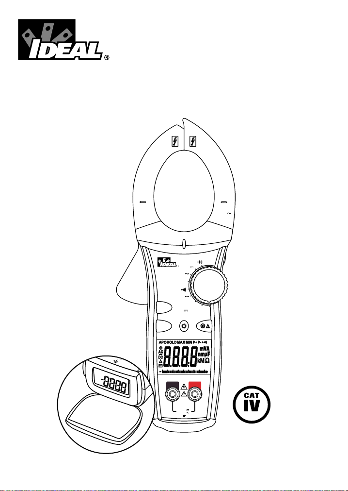
1000A Clamp Meters
w/TightSight™ Display
Instruction Manual
V/
Ω
COM
CAT.IV 600V
1000V
750V
CAT.III 1000V
MAX
True RMS
OFF
400
MAX
MIN
V
1000
A
Ω
V
HOLD
CAT.IV 600V
1000A
3002010 40
PEAK
CAT.III 1000V
A
61-774
600V
X
000V
750V
DCAC AM
PS
TightSight™ Display
Page 2

Page 2
Read First: Safety Information
Understand and follow operating instructions carefully. Use the meter only as specified in
this manual; otherwise, the protection provided by the meter may be impaired.
WARNING
To avoid possible electric shock, personal injury or death, follow these guidelines:
• Do not use if meter appears damaged. Visually inspect the meter to ensure case is not
cracked and back case is securely in place.
• Inspect and replace leads if insulation is damaged, metal is exposed, or probes are
cracked. Pay particular attention to the insulation surrounding the connectors.
• Do not use meter if it operates abnormally as protection maybe impaired.
• Do not use during electrical storms or in wet weather.
• Do not use around explosive gas, dust, or vapor.
• Do not apply more than the rated voltage to the meter.
• Do not use without the battery and the back case properly installed.
• Remove the test leads from the circuit prior to removing battery cap.
• Do not attempt to repair this unit as it has no user-serviceable parts.
CAUTION
To protect yourself, think "Safety First":
• Voltages exceeding 30VAC or 60VDC pose a shock hazard so use caution.
• Use appropriate personal protective equipment such as safety glasses, face shields,
insulating gloves, insulating boots, and/or insulating mats.
• Before each use:
- Perform a continuity test by touching the test leads together to verify the
functionality of the battery and test leads.
- Use the 3 Point Safety Method. (1) Verify meter operation by measuring a known
voltage. (2) Apply meter to circuit under test. (3) Return to the known live voltage
again to ensure proper operation.
• Never ground yourself when taking electrical measurements.
• Connect the black common lead to ground or neutral before applying the red test lead to
potential voltage. Disconnect the red test lead from the voltage first.
• Always work with a partner.
• When using the probes, keep fingers as far behind the probe tips as possible.
Page 3
V/
Ω
COM
CAT.IV 600V
1000V
750V
CAT.III 1000V
MAX
True RMS
OFF
400
MAX
MIN
V
1000
A
Ω
V
HOLD
CAT.IV 600V
1000A
3002010 40
PEAK
CAT.III 1000V
A
61-774
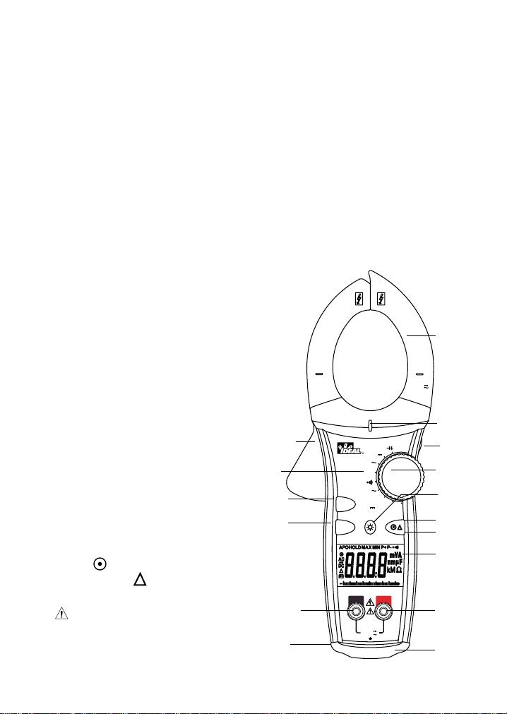
Features
1. Tapered jaws w/hook tip
2. Lever
3. Function Dial
4. Main Display (LCD)
5. Volts and resistance (V-Ω)
input terminal
6. Common (COM) input terminal
7. TightSight™ bottom display
8. Protective rubber boot
9. Measuring Functions
10. High Voltage (Hi-V) warning
11. Data Hold
12. Max/min
13. Peak max/min
14. Backlight
15. Range ( )
16. Relative mode ( )
Symbols on the Unit
• Warning - read the
instruction manual
• Cat IV - 600V Safety category
• Cat III - 1000V Safety category
Page 3
770 Series Common Features:
• Auto/manual ranging clamp meter • Large numbers and symbols displayed
• TightSight™ bottom display • Peak max/min, max/min, data hold
• Visual and audible indication when • Selectable Auto power off and low
voltage is present even when the meter battery indicator
is set on the wrong function for • Tapered jaws for reaching into tight spaces
enhanced safety • Hook tip for easier wire separation
• Measures 1000 AAC Current • Protective rubber boot
• Measures AC/DC Voltage & Resistance • Electronic overload protection on
• Audible continuity all ranges
• Bright, bold backlight • Cat IV-600V/Cat III-1000V
• 61-772 model is true rms sensing
• 61-774 model is true rms sensing, measures DC current and capacitance
1
10
11
3
15
16
4
5
9
12
13
14
6
8
7
2
Page 4
Page 4
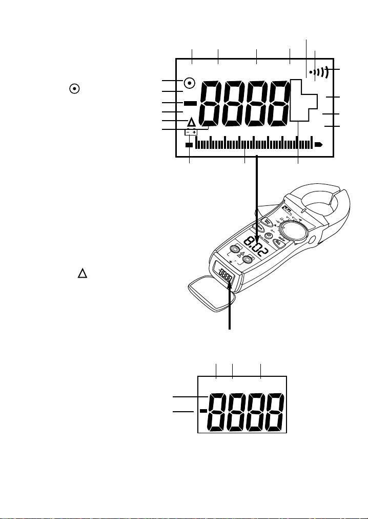
Main Display Icons
15. 4000 count display
16. AC measurement
17. DC measurement
18. Polarity indicator for DC
19. Range ( )
20. Auto Power Off
(APO)
21. Data Hold
22. Max/min
23. Peak max/min
24. Audible continuity
25. Volts
26. Amps
27. Farads
28. Ohms
29. Hertz
30. Units of measure
31. Analog bar graph
32. Low battery indicator
33. Relative ( )
TightSight™ Display Icons
34. 4000 count display
35. Polarity indicator for DC
36. DC measurement
37. AC measurement
38. Amps
APO HOLD MAX MIN P + P -
mVA
nmµF
kMΩ
Hz
AC
DC
DCAC AMPS
15
16
17
33
35
34
18
19
20
36 37 38
3132
21 22
25
26
30
27
28
29
23
24
Main Display
TightSight™ Bottom Display
6
1
-
7
7
4
COM
V
/
C
A
T
.
I
V
6
0
0
V
C
A
T
.
II
I
1
0
0
0
V
M
A
X
1
0
0
0
V
7
5
0
V
0
10
20
30 40
A
P
O
A
C
A
4
0
0
1
0
0
0
DCAC AMPS
Note: Only AC/DC amps units of measure are displayed in the TightSight™
display since primary use is for viewing current measurements in tight locations.
The display will show numerical values only for other functions. The main display
is to be used to view units of measure for all other functions.
Page 5

OPERATION:
High Voltage Warning (HI-V)
The meter beeps and lights an LED when > 30V AC/DC voltage is present through the test
leads of the meter. This enhanced safety feature alerts the user that dangerous voltage is present across the leads even if the meter is set on an incorrect function or range.
Note: This features does not work through the clamp head as the clamp is intended to only
measure current.
Auto/Manual Ranging Mode ( )
The meter defaults to autoranging mode when powered on. In this mode, the meter
automatically selects the best range to display the measurement. By pressing the Range ( )
button on the meter, the manual range mode will override the auto-ranging feature of the meter.
A ( ) appears in the upper left side of the display. Continue pressing the Range button until
the desired range is obtained. Use this mode to lock in a specific range for repeated
measurements. To return to the autoranging mode, either depress the Range button for greater
than 1 second or turn the meter off and then back on again.
Peak Max/Min Feature
Peak function captures peak voltage in the VAC function and peak current in the AAC function.
Both P+ and P- have 1 ms capture time. Set the meter to the desired function, press the
“PEAK” button and apply the setup to the circuit. The P+ will be displayed. Press the “PEAK”
button again to display the P-. Depress the peak button for >2 sec. to exit the peak feature.
Note: If a more accurate peak measurement is required, then calibration should be performed.
Depress the Peak button for >2 sec. until “CAL” appears in the display. The meter selfcalibrates to ±3% accuracy + 60 digits accuracy(400m/4VAC ranges unspecified).
Max/Min Feature
The Max records the maximum vaue measured over time while Min captures the minimum
value measured over time. Press the Max/Min button to activate this feature and to toggle
between Max, Min and Maxmin. “MAXMIN” displays the real time reading while still capturing
max and min values over time. Depressing the max/min button for >2 sec. exits the mode.
Note: To record max/min values over a time period >30 min, the Auto Power Off (APO) feature
must be defeated.
Data Hold Feature
Press the Hold button on the side of the meter to toggle in and out of the data hold mode.
“HOLD” appears in the upper left of the meter display when data hold is active. Use the data
hold feature to lock a measurement reading on the display. Press the Hold button again to
unlock the display and obtain a real-time reading.
Page 5
Page 6
Page 6
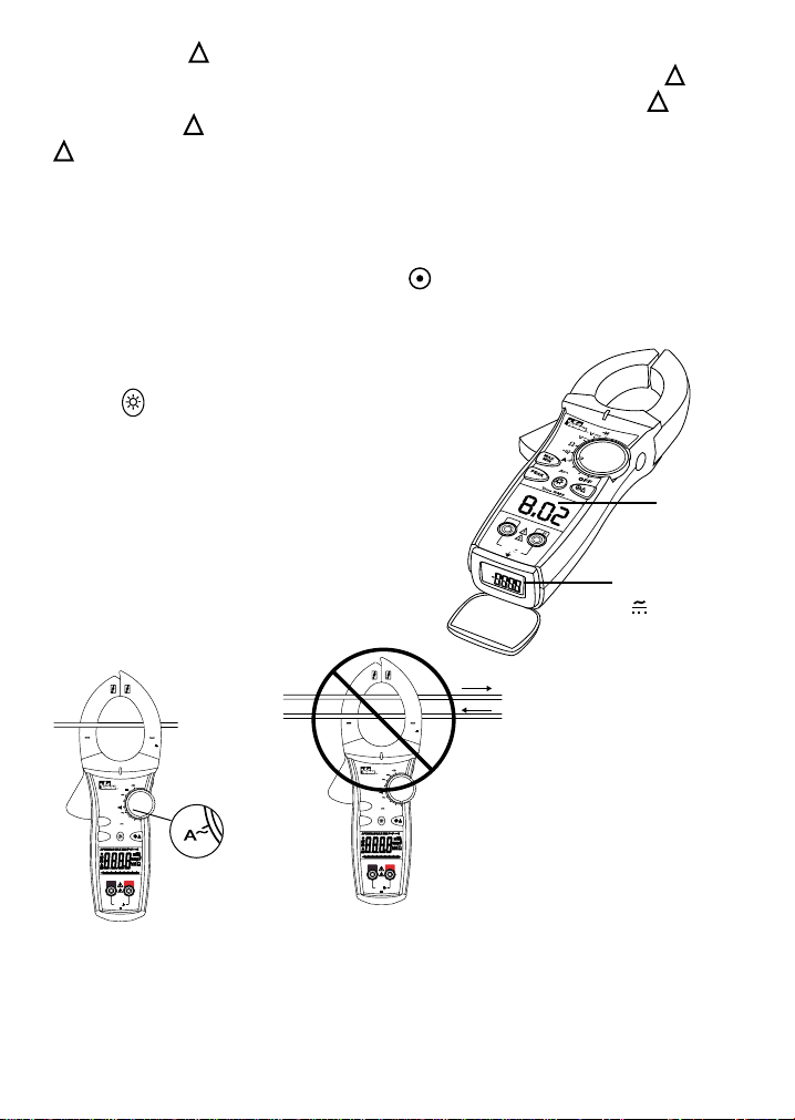
INCORRECT
Currents
cancel
CORRECT
Single
Conductor
only
Note: 61-774 model also measures DC Current.
V/
Ω
COM
CAT.IV 600V
1000V
750V
CAT.III 1000V
MAX
True RMS
OFF
400
MAX
MIN
V
1000
A
Ω
V
HOLD
CAT.IV 600V
1000A
3002010 40
PEAK
CAT.III 1000V
A
61-774
V/
Ω
COM
CAT.IV 600V
1000V
750V
CAT.III 1000V
MAX
True RMS
OFF
400
MAX
MIN
V
1000
A
Ω
V
HOLD
CAT.IV 600V
1000A
3002010 40
PEAK
CAT.III 1000V
A
61-774
H
N
Relative Mode ( ) (61-774 model only)
This mode is used to zero out the display before measuring DC current. Press the “ “button
to subtract out the non-zero number. Then, measure the DC amps. Pressing the “ “ button
again causes the “ “ to flash and the original offset number to be displayed. Depress the
” “ button for >2 sec. to exit this mode.
Selectable Auto Power Off (APO) Feature
The meter automatically powers itself down after about 30 minutes of no use. Press any
button, and the meter will wake up and display the last reading taken before power down. This
feature can be overridden by holding the Range ( ) button while turning the function switch
from Off to any other position. When APO is defeated, the “APO” will be removed from the
display. Turning the meter off will restore the APO default.
Backlight
Press the button in the middle of the meter to turn
the backlight on and off. The green backlight will remain
lit for about 4.5 minutes before it automatically turns off
to conserve battery power. Also, the TightSight™ bottom
display only lights while the meter is in the Amp function
to minimize battery drain.
Note: Backlight consumes 4x the battery power.
Measuring AC Current (Amps):
Backlight on in
all functions.
Backlight on
function
only
A
6
1
-
7
7
4
4
0
0
1000
A
P
O
A
C
0
D
C
A
C
A
1
0
COM
2
0
3
0
V
4
0
/
CAT. IV 600V
CAT. III 1000V
MAX
1000V
750V
A
M
P
S
Page 7

Measuring Resistance (Ohms):
• Verify the circuit is de-energized to
obtain accurate measurements.
Measuring Voltage:
Page 7
V/
Ω
COM
CAT.IV 600V
1000V
750V
CAT.III 1000V
MAX
True RMS
OFF
400
MAX
MIN
V
1000
A
Ω
V
HOLD
CAT.IV 600V
1000A
3002010 40
PEAK
CAT.III 1000V
A
61-774
AC Voltage DC Voltage
V/
Ω
COM
CAT.IV 600V
1000V
750V
CAT.III 1000V
MAX
True RMS
OFF
400
MAX
MIN
V
1000
A
Ω
V
HOLD
CAT.IV 600V
1000A
3002010 40
PEAK
CAT.III 1000V
A
61-774
V/
Ω
COM
CAT.IV 600V
1000V
750V
CAT.III 1000V
MAX
True RMS
OFF
400
MAX
MIN
V
1000
A
Ω
V
HOLD
CAT.IV 600V
1000A
3002010 40
PEAK
CAT.III 1000V
A
61-774
Page 8
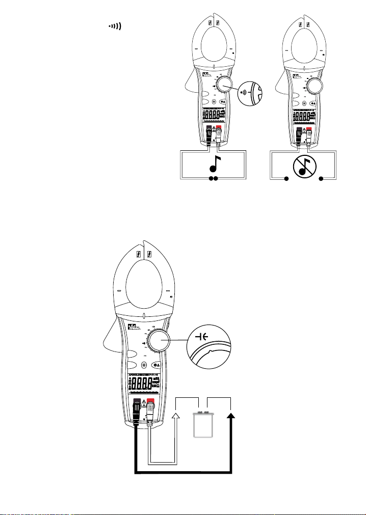
Verifying Continuity ( ):
• Verify the circuit is de-energized.
• The meter will sense the level of
resistance and beep if the resistance
is less than 35 Ω to confirm that
continuity is present.
Page 8
V/
Ω
COM
CAT.IV 600V
1000V
750V
CAT.III 1000V
MAX
True RMS
OFF
400
MAX
MIN
V
1000
A
Ω
V
HOLD
CAT.IV 600V
1000A
3002010 40
PEAK
CAT.III 1000V
A
61-774
V/
Ω
COM
CAT.IV 600V
1000V
750V
CAT.III 1000V
MAX
True RMS
OFF
400
MAX
MIN
V
1000
A
Ω
V
HOLD
CAT.IV 600V
1000A
3002010 40
PEAK
CAT.III 1000V
A
61-774
Closed
Circuit
Open
Circuit
Capacitance (61-774):
V/
Ω
COM
CAT.IV 600V
1000V
750V
CAT.III 1000V
MAX
True RMS
OFF
400
MAX
MIN
V
1000
A
Ω
V
HOLD
CAT.IV 600V
1000A
3002010 40
PEAK
CAT.III 1000V
A
61-774
Page 9
Page 9
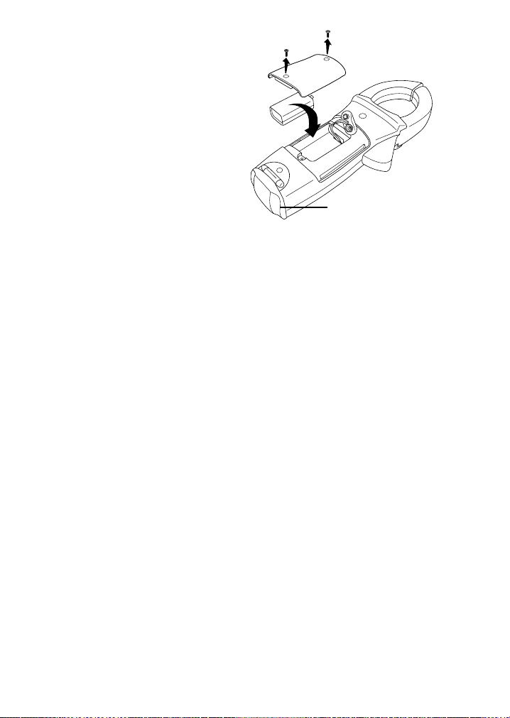
Battery Replacement:
• Ensure test leads are disconnected from
circuit or components.
• Remove test leads from input jacks
on meter.
• Remove the two screws from the
battery cap.
• Remove the battery cap.
• Replace battery with a new 9V battery.
• Assemble the battery cap to the
meter and re-tighten the screws.
Maintenance:
Clean the case with a damp cloth and mild detergent. Do not use abrasives or solvents.
Service and Replacement Parts:
This unit has no user-serviceable parts.
For replacement parts or to inquire about service information contact IDEAL INDUSTRIES,
INC. at 1-877-201-9005 or visit our website www.testersandmeters.com.
Warranty Statement:
This tester is warranted to the original purchaser against defects in material and
workmanship for the lifetime of the product. During this warranty period, IDEAL
INDUSTRIES, INC. will, at its option, replace or repair the defective unit, subject to
verification of the defect or malfunction. This warranty does not apply to defects resulting
from abuse, neglect, accident, unauthorized repair, alteration, or unreasonable use of the
instrument.
Any implied warranties arising out of the sale of an IDEAL product, including but not limited
to implied warranties of merchantability and fitness for a particular purpose, are limited to
the above. The manufacturer shall not be liable for loss of use of the instrument or other
incidental or consequential damages, expenses, or economic loss, or for any claim or
claims for such damage, expenses or economic loss.
State laws vary, so the above limitations or exclusions may not apply to you. This warranty
gives you specific legal rights, and you may also have other rights which vary from state to
state.
-
+
Replacement boot is
available.
Page 10

Page 10
Specifications:
Displays: 3-3/4 digit LCD with 4000 counts for both displays
Backlight: Green illumination with auto-off after 4.5 minutes
Analog Bargraph: 41 segment LCD with measurements of 20 times per second
Polarity: Automatic, positive implied, negative (-) polarity indication.
Overrange: "OL" indication is displayed.
Zero: Automatic
Measure Rate: Samples 2 times per second, nominal.
Auto Power Off: Approximately after 30 minutes of non-use.
Battery Life: 200 hours continuous with Alkaline (61-772)
150 hours continuous with Alkaline (61-774)
Low Battery Indication: The " " is displayed when battery voltage drops below
operating level.
Power Supply: (1) 9V battery (NEDA 1604, JIS 006P, IEC 6F22)
Includes an isolated battery compartment.
Accuracy: Stated accuracy at 23°C ±5°C, <75% R.H.
Temperature 0.1 x (specified accuracy) per °C,
Coefficient: (0°C to 18°C, 28°C to 50°C).
Altitude: 6561.7 ft. (2000m)
Operating Environment: 32°F to 122°F (0°C to 50°C) at < 70% R.H.
Storage Environment: -4°F to 140°F (-20°C to 60°C) at < 80% R.H. with battery
removed from meter
Jaw Opening: Accepts a 2.0" (51mm) conductor
Dimensions: 10.6”H x 4.1”W x 1.9”D (270mmH x 103mmW x 48.5mmD)
Weight: 1.1 lbs. (500g) including battery
Accessories included: Carrying Case, Test Leads with alligator clip, (1) 9V
battery, operating instructions.
Safety: Complies with EN 61010-1, EN 61010-2-032, UL 61010-1,
IEC 61010-2-032, IEC 61010-031 specifications.
Rated for Cat IV-600V/Cat III-1000V
Double Insulation
Instrument has been evaluated and complies with insulation category IV (overvoltage
category IV). Pollution degree 2 in accordance with IEC-644. Indoor use.
CUS
N12966
Page 11
Page 11
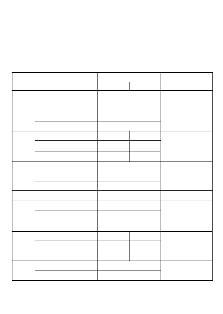
Ranges & Accuracies:
AC Converter: 61-772, 61-774 models are true rms sensing.
Accuracy: Accuracy is specified as +/-(a percentage of the reading + a fixed amount) at
23°C±5°C (73.4°F ± 9°F), less than 75% relative humidity.
Temperature Coefficient: 0.1 times the applicable accuracy specification per degree C
from 0°C to 18°C and 28°C to 50°C (32°F to 64°F and 82°F to 122°F)
*Accuracy stated for crest factor ≤ 3 at full scale and ≤ 6 at half scale
Input impedance: 400mV: >50MΩ; 4V: 10MΩ; 40V~ 1000V: 9.1MΩ
Accuracy
Function
Range and Overload
Resolution
61-772 61-774
Protection
400.0/1000A
(0~600A, 50-60Hz) 1.7% + 10
400.0/1000A (0~600A, 60-400Hz) 3.0% + 10
AC Current*
400.0/1000A (600~1000A, 50-60Hz) 2.5% + 10
1000 AAC
400.0/1000A (600~1000A, 60-400Hz) 3.5% + 10
400.0/1000A
(0~400A) N/A 1.5% + 5
DCCurrent 400.0/1000A
(400~800A)
N/A 2.0% + 5 1000 ADC
400.0/1000A
(800~1000A) N/A 3.0% + 5
400.0m (50-60Hz) 1.2% + 8
1000VDC or
ACVoltage 4.000/40.00/400.0V
(50-500Hz) 1.2% + 8
750V (
50-500Hz) 1.5% + 8
750VAC rms
DCVoltage 400.0m/4.000/40.00/400.0/1000V 0.5% + 2 1000VDC or 750 VAC rms
400.0/4.000k/40.00k/400.0kΩ 1.0% + 4
Resistance 4.000MΩ 5.0% + 4 600 VDC or AC rms
40.00MΩ (specified to 10MΩ) 12.0% + 5
4.000µF N/A 3.0% + 10
Capacitance 40.00µ/400.0µ F N/A 3.0% + 5 600 VDC or AC rms
4.000mF N/A 5.0% + 20
Audible indication < 35Ω ••
Continuity
Response time: 500ms • •
600 VDC or AC rms
Page 12

IDEAL INDUSTRIES, INC.
Sycamore, IL 60178
Technical Hotline: 877- 201-9005
www.testersandmeters.com
ND 4969-1 Made in Taiwan
Page 13

#61-772
#61-774
Medidores de pinza de 1000 A
con pantalla TightSight™
Manual de Instrucciones
V/
Ω
COM
CAT.IV 600V
1000V
750V
CAT.III 1000V
MAX
True RMS
OFF
400
MAX
MIN
V
1000
A
Ω
V
HOLD
CAT.IV 600V
1000A
3002010 40
PEAK
CAT.III 1000V
A
61-774
600V
V
X
000V
750V
DCAC AM
PS
Pantalla TightSight™
Page 14

Page 2
Lea primero: Información de seguridad
Comprenda y siga estas instrucciones de operación cuidadosamente. Utilice el medidor
sólo según se especifica en este manual; de lo contrario, la protección que él proporciona
podría deteriorarse.
ADVERTENCIA
Para evitar una posible descarga eléctrica, lesiones personales o la muerte, siga estas
instrucciones:
• No utilice el medidor si se lo ve dañado. Inspeccione visualmente el medidor para
asegurarse de que la caja no esté agrietada y la caja posterior esté colocada firmemente.
• Inspeccione y reemplace los cables si el aislamiento está dañado, el metal está al
descubierto o las sondas están agrietadas. Preste atención en particular al aislamiento
que rodea los conectores.
• No utilice el medidor si funciona de forma anormal, ya que la protección puede haberse
dañado.
• No lo utilice durante tormentas eléctricas o con tiempo húmedo.
• No lo utilice cerca de gases, polvo o vapores explosivos.
• No aplique al medidor un voltaje mayor que el voltaje nominal.
• No lo utilice sin la batería y sin la caja posterior bien instalada.
• Quite los cables de prueba del circuito antes de quitar la tapa de la batería.
• No intente reparar esta unidad, ya que no tiene piezas reparables por el usuario.
PRECAUCIÓN
Para protegerse, piense en la ‘Seguridad ante todo’:
• Los voltajes que superen 30 V CA o 60 V CC presentan un peligro de descarga, por lo
que debe tener cuidado.
• Utilice equipos de protección personal apropiados, como gafas de seguridad, máscaras,
guantes aislantes, botas aislantes y esteras aislantes.
• Antes de cada uso:
- Realice una prueba de continuidad poniendo en contacto los cables de prueba entre
sí, para verificar la funcionalidad de la batería y los cables de prueba.
- Use el Método de Seguridad de 3 Puntos. (1) Verifique la operación del medidor
midiendo un voltaje conocido. (2) Aplique el medidor al circuito bajo prueba. (3)
Vuelva a probar nuevamente con el voltaje real conocido para asegurar un
funcionamiento correcto.
• Nunca se conecte a tierra cuando tome medidas eléctricas.
• Conecte el cable común negro a tierra o al neutro antes de aplicar el cable de prueba
rojo a un punto en el que pueda haber voltaje. Desconecte primero el cable de prueba
rojo del voltaje.
• Trabaje siempre con un compañero.
• Al usar las sondas, mantenga los dedos lo más detrás posible de las puntas de las
mismas.
Page 15

Page 3
Características comunes de la Serie 770:
• Medidor de pinza con selección de • Indicación con números y símbolos grandes
gama automática y manual • Pico máx./mín., Máximo/Mínimo, retención
• Pantalla inferior TightSight™ de datos
• Indicación visual y audible de • Apagado automático seleccionable e
presencia de voltaje aun cuando el indicador de batería descargada
medidor esté erróneamente configurado • Mordazas ahusadas, para penetrar en
para otra función, para mejorar espacios estrechos
la seguridad • Punta en forma de gancho, para facilitar
• Medida de corriente hasta 1000 A CA la separación de cables
• Medida de voltaje de CA/CC y resistencia • Funda protectora de goma
• Verificación de continuidad con • Protección electrónica contra sobrecarga
indicación audible en todas las gamas
• IIluminación posterior brillante y definida • Cat IV-600 V / Cat III-1000 V
• El modelo 61-772 detecta valores eficaces (rms) reales
• El modelo 61-774 detecta valores eficaces (rms) reales, y mide corriente continua (CC) y
capacidad
Características
1. Mordazas ahusadas con punta en forma de gancho
2. Palanca
3. Selector de funciones
4. Pantalla principal de cristal líquido (LCD)
5. Terminal de entrada para voltaje y resistencia (V-Ω)
6. Terminal de entrada común (COM)
7. Pantalla inferior TightSight™
8. Funda protectora de goma
9. Funciones de medida
10. Advertencia de alto voltaje (Hi-V)
11. Retención de datos
12. Máximo/Mínimo
13. Pico máx./mín.
14. Iluminación posterior
15. Gama ( )
16. Modo relativo ( )
Símbolos de la unidad
• Advertencia: lea el manual de instrucciones
• Cat IV: Categoría de seguridad 600 V
• Cat III: Categoría de seguridad 1000 V
V/
Ω
COM
CAT.IV 600V
1000V
750V
CAT.III 1000V
MAX
True RMS
OFF
400
MAX
MIN
V
1000
A
Ω
V
HOLD
CAT.IV 600V
1000A
3002010 40
PEAK
CAT.III 1000V
A
61-774
1
10
11
3
15
16
4
5
9
12
13
14
6
8
7
2
Page 16

Íconos de la pantalla principal
15. Pantalla de 4000 cuentas
16. Medida de CA
17. Medida de CC
18. Indicador de polaridad
para CC
19. Gama ( )
20. Apagado automático
(Auto Power Off – APO)
21. Retención de datos
22. Máximo/Mínimo
23. Pico máx./mín.
24. Verificación de continuidad
con indicación audible
25. Volts
26. Amperes
27. Farads
28. Ohms
29. Hertz
30. Unidades de medida
31. Gráfico analógico de barras
32. Indicador de batería descargada
33. Modo relativo ( )
Íconos de la pantalla
TightSight™
34. Pantalla de 4000 cuentas
35. Indicador de polaridad para CC
36. Medida de CC
37. Medida de CA
38. Amperes
APO HOLD MAX MIN P + P -
mVA
nmµF
kMΩ
Hz
AC
DC
DCAC AMPS
15
16
17
33
35
34
18
19
20
36 37 38
3132
21 22
25
30
23
Pantalla principal
Pantalla inferior TightSight™
6
1
-
7
7
4
COM
V
/
C
A
T
.
I
V
6
0
0
V
C
A
T
.
I
II
1
0
0
0
V
M
A
X
1
0
0
0
V
7
5
0
V
0
10
20
30 40
A
P
O
A
C
A
4
0
0
1
0
0
0
DCAC AMPS
Nota: se indican en la pantalla TightSight™ únicamente las unidades de medida de corri-
ente CC y CA (amperes), porque su uso principal es para observar medidas de corriente en
lugares estrechos. La pantalla mostrará los valores numéricos para las otras funciones únicamente. Para ver las unidades de medida de todas las demás funciones se debe utilizar la
Page 4
Page 17

Page 5
OPERACIÓN:
Advertencia de alto voltaje (Hi-V)
El medidor emite un pitido y enciende un LED cuando entre sus cables de prueba está presente un voltaje mayor que 30 V CA o CC. Esta función de seguridad mejorada advierte al
usuario sobre la presencia de un voltaje peligroso entre los cables, aun cuando el medidor
esté erróneamente configurado para otra función o gama.
Nota: esta característica no actúa con el cabezal de pinza, ya que éste está destinado a
medir únicamente corriente.
Modo de selección de gama automático/manual ( )
El medidor, al encenderse, va por defecto al modo de selección automática de gama. En este
modo, el medidor selecciona automáticamente la mejor gama para indicar la medida. Al presionar el botón Range (Gama) ( ) del medidor, el modo de selección manual de gama
prevalecerá sobre la función de selección automática de gama del medidor. En el lado superior
izquierdo de la pantalla aparece un ( ). Continúe presionando el botón Range (Gama) hasta
llegar a la gama deseada. Utilice este modo para mantener fija una gama específica cuando
deba hacer medidas repetidas. Para volver al modo de selección automática de gama, puede
mantener presionado el botón Range (Gama) durante más de 1 segundo, o apagar el medidor y
encenderlo nuevamente.
Característica de pico máx./mín.
La función de pico captura el voltaje de pico en la función de volts CA, y la corriente de pico en
la función de amperes CA. El tiempo de captura, tanto para el valor de pico positivo (P+) como
para el negativo (P-), es 1 ms. Configure el medidor para la función deseada, presione el botón
PEAK (PICO), y conecte el equipo al circuito. En la pantalla se indicará el símbolo P+. Si presiona el botón PEAK (PICO) nuevamente, en la pantalla se indicará el símbolo P-. Para abandonar la característica de amplitud, oprima el botón PEAK (PICO) durante más de 2 segundos.
Nota: Si se necesita una medida de pico más precisa, se debe realizar una calibración. Para
ello, oprima el botón PEAK (PICO) durante más de 2 segundos, hasta que en la pantalla se lea
‘CAL’. El medidor se autocalibra, con una precisión de ± 3 % + 60 dígitos precisión
(400m/4VAC gamas inespecíficas).
Característica Máximo/Mínimo
Cuando se selecciona Max (Máximo), queda registrado el máximo valor medido en un período
de tiempo determinado, mientras que cuando se selecciona Min (Mínimo) se captura el mínimo valor medido en un período de tiempo determinado. Para activar esta característica, así
como para alternar entre Max, Min y Maxmin, presione el botón Max/Min. Cuando se selecciona ‘Maxmin’ se indica en la pantalla la lectura en tiempo real, mientras se continúa capturando los valores máximo o mínimo medidos en un período de tiempo determinado. Para
abandonar este modo, presione el botón Max/Min durante más de 2 segundos. Nota: Para
registrar los valores máximos o mínimos medidos en un período de tiempo mayor que 30 minutos, debe anularse la característica de apagado automático (Auto Power Off – APO).
Page 18

Page 6
Característica de retención de datos
Presione el botón Hold (Retención), ubicado en el costado del medidor, para entrar y salir
sucesivamente del modo de retención de datos. Cuando la función de retención de datos está
activa, aparece en la parte superior izquierda de la pantalla del medidor la leyenda ‘HOLD’
(RETENCIÓN). Utilice la característica de retención de datos para fijar una lectura de medida
en la pantalla. Para que la indicación de la pantalla deje de estar fija, y pueda obtenerse una
lectura en tiempo real, vuelva a presionar el botón Hold (Retención).
Modo relativo ( ) (Modelo 61-774 únicamente)
Este modo se utiliza para la puesta a cero de la indicación de la pantalla antes de medir
corriente continua (CC). Para restar el número distinto de cero, presione el botón ‘ ‘. Luego
mida la corriente continua (CC) en amperes. Al presionar el botón ‘ ‘ nuevamente, el
símbolo ‘ ‘ destella, y vuelve a aparecer el número original que se había sustraído. Para
abandonar este modo, oprima el botón ‘ ‘ durante más de 2 segundos.
Característica seleccionable de apagado automático (Auto Power Off – APO)
El medidor se desactiva automáticamente después de 30 minutos sin uso. Si en esa situación
presiona cualquier botón, el medidor se reactivará e indicará en su pantalla la última lectura
tomada antes de desactivarse. Esta característica puede ser anulada manteniendo presionado
el botón Range (Gama) ( ) mientras se hace girar el conmutador de funciones desde la
posición OFF (APAGADO) hasta cualquier otra. Cuando se anula el apagado automático, la
leyenda ‘APO’ desaparecerá de la pantalla. Al apagar el medidor, se restaurará la característica
de apagado automático por defecto.
Iluminación posterior
Para encender y apagar la iluminación posterior,
presione el botón , ubicado en la parte media del
medidor. La iluminación posterior verde permanecerá
encendida durante unos 4,5 minutos y luego se
apagará automáticamente, para preservar la energía
de la batería. Además, la pantalla inferior TightSight™
se ilumina únicamente cuando el medidor está
configurado para la función Amp, para minimizar
la descarga de la batería.
Nota: La iluminación posterior cuadruplica el
consumo de la batería.
Iluminación posteri-
or encendida en
todas las funciones.
Iluminación posterior
encendida en la función
únicamente.
A
D
6
1
-
7
7
4
40
0
1000
A
P
O
A
C
0
1
0
COM
2
0
3
0
V
4
0
/
CAT. IV 600V
CAT. III 1000V
MAX
1000V
750V
C
A
C
A
M
P
S
A
Page 19

Page 7
Medida de corriente alterna (CA) (amperes):
Medida de voltaje:
INCORRECTO
Las corrientes
se anulan
CORRECTO
Sólo un conductor único
Nota: El modelo 61-774 mide también corriente continua (CC).
V/
Ω
COM
CAT.IV 600V
1000V
750V
CAT.III 1000V
MAX
True RMS
OFF
400
MAX
MIN
V
1000
A
Ω
V
HOLD
CAT.IV 600V
1000A
3002010 40
PEAK
CAT.III 1000V
A
61-774
V/
Ω
COM
CAT.IV 600V
1000V
750V
CAT.III 1000V
MAX
True RMS
OFF
400
MAX
MIN
V
1000
A
Ω
V
HOLD
CAT.IV 600V
1000A
3002010 40
PEAK
CAT.III 1000V
A
61-774
H
N
Voltaje de CA Voltaje de CC
V/
Ω
COM
CAT.IV 600V
1000V
750V
CAT.III 1000V
MAX
True RMS
OFF
400
MAX
MIN
V
1000
A
Ω
V
HOLD
CAT.IV 600V
1000A
3002010 40
PEAK
CAT.III 1000V
A
61-774
V/
Ω
COM
CAT.IV 600V
1000V
750V
CAT.III 1000V
MAX
True RMS
OFF
400
MAX
MIN
V
1000
A
Ω
V
HOLD
CAT.IV 600V
1000A
3002010 40
PEAK
CAT.III 1000V
A
61-774
Page 20

Page 8
Medida de resistencia (ohms):
• Para obtener medidas precisas,
verifique que el circuito esté
desenergizado.
Verificación de continuidad ( ):
• Verifique que el circuito esté
desenergizado.
• El medidor detectará el nivel
de resistencia y emitirá un pitido
si la resistencia es menor que
35 Ω, para confirmar que existe
continuidad.
V/
Ω
COM
CAT.IV 600V
1000V
750V
CAT.III 1000V
MAX
True RMS
OFF
400
MAX
MIN
V
1000
A
Ω
V
HOLD
CAT.IV 600V
1000A
3002010 40
PEAK
CAT.III 1000V
A
61-774
V/
Ω
COM
CAT.IV 600V
1000V
750V
CAT.III 1000V
MAX
True RMS
OFF
400
MAX
MIN
V
1000
A
Ω
V
HOLD
CAT.IV 600V
1000A
3002010 40
PEAK
CAT.III 1000V
A
61-774
V/
Ω
COM
CAT.IV 600V
1000V
750V
CAT.III 1000V
MAX
True RMS
OFF
400
MAX
MIN
V
1000
A
Ω
V
HOLD
CAT.IV 600V
1000A
3002010 40
PEAK
CAT.III 1000V
A
61-774
Circuito
cerrado
Circuito
interrumpido
Page 21

Page 9
Capacidad (61-774):
Reemplazo de la batería:
• Asegúrese de que los cables de prueba estén
desconectados del circuito o de los componentes.
• Retire los cables de prueba de los conectores
hembra (jacks) de entrada del medidor.
• Quite los dos tornillos de la tapa de la batería.
• Retire la tapa de la batería.
• Reemplace la batería por una batería nueva de 9 V.
• Monte la tapa de la batería en el medidor, y
vuelva a apretar los tornillos.
Mantenimiento:
• Limpie la caja con un trapo humedecido y detergente suave.
No use abrasivos ni disolventes.
Piezas de servicio y de repuesto:
Esta unidad no contiene piezas reparables por el usuario.
Si necesita piezas de repuesto o consultar sobre información de servicio, contacte con
IDEAL INDUSTRIES, INC., llamando al 1-877-201-9005, o visite nuestro sitio Web
www.testersandmeters.com.
V/
Ω
COM
CAT.IV 600V
1000V
750V
CAT.III 1000V
MAX
True RMS
OFF
400
MAX
MIN
V
1000
A
Ω
V
HOLD
CAT.IV 600V
1000A
3002010 40
PEAK
CAT.III 1000V
A
61-774
-
+
Puede obtenerse una
funda de repuesto..
Page 22

Page 10
Garantía:
This tester Se garantiza al comprador original del medidor contra los defectos de material y
mano de obra durante la vida útil del producto. Durante este período de garantía, IDEAL
INDUSTRIES, INC. podrá, a su elección, reemplazar o reparar la unidad defectuosa, sujeta a
verificación del defecto o falla. Esta garantía no se aplica a defectos resultantes del mal
uso, negligencia, accidente, reparación no autorizada, alteración o uso irracional de este
instrumento.
Cualquier garantía implícita originada en la venta de un producto IDEAL, incluyendo -pero
sin limitarse a ellas- garantías implícitas de comerciabilidad y adecuación para un
propósito particular, se limitan a lo indicado anteriormente. El fabricante no será
responsable por la pérdida del uso del instrumento u otros daños emergentes o
concomitantes, gastos o pérdida económica, o por cualquier reclamación de dichos daños,
gastos o pérdidas económicas.
Las leyes estatales varían, por lo que las limitaciones o exclusiones anteriores pueden no
aplicarse en su caso. Esta garantía le da derechos legales específicos, y usted puede tener
también otros derechos que varían de estado a estado.
Page 23

Page 11
Especificaciones:
Pantallas: Ambas pantallas son de cristal líquido (LCD) de 3-3/4 dígitos,
4000 cuentas
Iluminación posterior: Iluminación verde, con apagado automático después de 4,5 minutos
Gráfico analógico de Indicador de cristal líquido (LCD) de 41 segmentos, con 20 medidas
barras: por segundo
Polaridad: Automática, positiva implícita, indicación de polaridad negativa (-).
Fuera de gama: Se indica en la pantalla ‘OL’.
Cero: Automático
Frecuencia de medición: 2 muestras por segundo (nominal).
Apagado automático
(Auto Power Off – APO): Después de aproximadamente 30 minutos sin uso.
Vida de la batería: 200 horas continuas, con batería alcalina (61-772)
150 horas continuas, con batería alcalina (61-774)
Indicación de batería Se indica en la pantalla ‘ ‘ cuando el voltaje de la batería cae por
descargada: debajo del nivel de operación.
Fuente de alimentación: (1) batería de 9 V (NEDA1604, JIS 006P, IEC 6F22)
Incluye un compartimiento para batería aislado.
Precisión: Precisión especificada a 23 ºC ±5 °C, humedad relativa < 75 %.
Coeficiente de
temperatura: 0,1 x (precisión especificada) por °C (0°C a 18°C, 28°C a 50°C)
Altitud: 2000 m (6561,7 pies)
Ambiente de operación: 0 ºC a 50 ºC (32 ºF a 122 ºF), humedad relativa < 70 %.
Ambiente de -20 ºC a 60 ºC (-4 ºF a 140 ºF), humedad relativa < 80%, con la
almacenamiento: batería extraída del medidor.
Abertura de la mordaza: Acepta un conductor de 51mm (2,0")
Dimensiones: 270 mm [altura] x 103 mm [ancho] x 48,5 mm [prof.]
(10,6" [altura] x 4,1" [ancho] x 1,9" [prof.])
Peso: 500 g (1,1 lb) con batería incluida
Accesorios incluidos: Estuche portátil, Cables de prueba con pinzas cocodrilo, (1) batería
de 9 V, instrucciones de operación.
Seguridad: Cumple con las especificaciones EN61010-1, EN61010-2-032,
UL61010-1, IEC61010-2-032, IEC61010-031,
Especificación Cat IV-600 V / Cat III-1000 V.
Aislamiento doble
El instrumento ha sido evaluado, y cumple con la categoría IV de aislamiento (categoría IV de
sobrevoltaje). Grado 2 de contaminación, de acuerdo con IEC-644. Uso en interiores.
CUS
N12966
Page 24

Page 12
Gamas y precisiones:
Convertidor de CA: 61-772 y 61-774 detectan valores eficaces (rms) reales.
Precisión: La precisión se especifica como +/- (un porcentaje de la lectura + una
cantidad fija) a 23 °C ± 5 °C (73,4 °F ± 9 °F), y una humedad relativa menor que 75 %.
Coeficiente de temperatura: 0,1 veces la especificación aplicable de precisión por
grado C, desde 0 ºC hasta 18 ºC y desde 28 ºC hasta 50 ºC (32 ºF a 64 ºF, y 82 ºF a 122 ºF)
*Precisión especificada para factor de cresta ≤ 3 a plena escala, y ≤ 6 a mitad de escala
Impedancia de entrada: 400 mV: >50MΩ; 4 V: 10 MΩ; 40 V~ 1000 V: 9,1 MΩ
Precisión
Función
Gama y Protección contra
Resolución
61-772 61-774
sobrecarga
400,0/1000A
(0~600A, 50-60Hz) 1,7% + 10
Corriente
400,0/1000A (0~600A, 60-400Hz) 3,0% + 10
alterna (CA)*
400,0/1000A (600~1000A, 50-60Hz) 2,5% + 10
1000 A CA
400,0/1000A (600~1000A, 60-400Hz) 3,5% + 10
Corriente
400,0/1000A
(0~400A) N/A 1,5% + 5
continua
400,0/1000A (400~800A) N/A 2,0% + 5 1000 A CC
(CC)
400,0/1000A (800~1000A) N/A 3,0% + 5
Voltaje de
400,0m (50-60Hz)
1,2% + 8
1000 V CC o 750 V CA
CA
4,000/40,00/400,0V
(50-500Hz) 1,2% + 8
750V (50-500Hz) 1,5% + 8
eficaces (rms)
Voltaje de CC
400,0m/4,000/40,00/400,0/1000V 0,5% + 2 1000 V CC o 750 V CA eficaces (RMS)
400,0/4,000k/40,00k/400,0kΩ 1,0% + 4
Resistencia 4,000MΩ 5,0% + 4 600 V CC o CA eficaces (rms)
40,00MΩ (especificación a 10MΩ) 12% + 5
4,000µF N/A 3,0% + 10
Capacidad 40,00µ/400,0µ F N/A 3,0% + 5 600 V CC o CA eficaces (rms)
4,000mF N/A 5,0% + 20
Indicación audible: < 35Ω ••
Continuidad
Tiempo de respuesta: 500ms • •
600 V CC o CAeficaces (rms)
Page 25

Page 13
#61-772
#61-774
Pince ampérimétrique de 1000A avec
affichage TightSight™
Mode d’emploi
V/
Ω
COM
CAT.IV 600V
1000V
750V
CAT.III 1000V
MAX
True RMS
OFF
400
MAX
MIN
V
1000
A
Ω
V
HOLD
CAT.IV 600V
1000A
3002010 40
PEAK
CAT.III 1000V
A
61-774
600V
V
X
000V
750V
DCAC AM
PS
Affichage TightSight™
Page 26

Page 14
Lire en premier : Informations concernant la sécurité
Veiller à comprendre et à se conformer scrupuleusement au mode d’emploi. N’utiliser le
multimètre que de la façon spécifiée dans le présent manuel ; à défaut, la protection offerte
par le multimètre pourra être compromise.
AVERTISSEMENT
Pour éviter tout risque d’électrocution, de lésions personnelles ou de mort, se conformer
aux directives suivantes :
• Ne pas utiliser le multimètre s’il paraît endommagé. Examiner le multimètre pour
s’assurer que son boîtier n’est pas fissuré et que sa partie arrière est bien assujettie.
• Inspecter et remplacer les conducteurs si l’isolant est endommagé, le métal exposé ou
les sondes fendues. Porter une attention particulière à l’isolant entourant les
connecteurs.
• Ne pas utiliser le multimètre s’il fonctionne de manière anormale, la protection qu’il offre
pouvant être compromise.
• Ne pas utiliser par temps orageux ou dans la pluie.
• Ne pas utiliser à proximité de gaz, de poussière ou de vapeurs explosifs.
• Ne pas soumettre le multimètre à une tension supérieure à la tension nominale.
• Ne pas utiliser sans la pile ou si l’arrière du boîtier n’est pas bien monté.
• Retirer les fils d’essai du circuit avant de retirer le capuchon de pile.
• Ne pas tenter de réparer cet appareil. Il ne comporte aucune pièce réparable par
l’utilisateur.
ATTENTION
Afin d’assurer sa propre protection, penser « Sécurité avant tout » :
• Les tensions supérieures à 30 V c.a. ou 60 V c.c. posent un risque d’électrocution, faire
donc preuve de prudence.
• Utiliser du matériel de protection adéquat, tels que des lunettes, des écrans faciaux, des
gants isolants, des bottes isolantes et/ou des tapis isolants.
• Avant chaque utilisation :
- Procéder à un essai de continuité et mettant les fils d’essai en contact l’un avec
l’autre afin de contrôler le fonctionnement de la pile et des fils d’essai.
- Utiliser la méthode de sécurité en 3 points. (1) Vérifier le fonctionnement du
multimètre en mesurant une tension connue. (2) Appliquer le multimètre au circuit
en cours de contrôle. (3) Retourner à la tension active connue pour vérifier le bon
fonctionnement.
• Ne jamais se mettre à la terre quand on procède à des mesures électriques.
• Connecter le conducteur commun noir à la terre ou au neutre avant d’appliquer le
conducteur d’essai rouge sur la tension potentielle. Commencer par déconnecter le
conducteur d’essai rouge de la tension.
• Travailler toujours avec un équipier.
• Quand on se sert des sondes, tenir les doigts aussi loin que possible des pointes de
sonde.
Page 27

Page 15
Caractéristiques communes de la Série 770 :
• Multimètre à pince à sélection de plages • Maxi/mini crête, maxi/mini, rétention de
automatique/manuelle données
• Affichage inférieur TightSight™ • Coupure automatique et témoin de
• Pour un surcroît de sécurité, indication décharge de pile sélectionnables
visuelle et audible en présence de tension • Mâchoires effilées permettant de travailler
même quand l’ampèremètre est réglé sur dans des espaces restreints
la mauvaise fonction. • Bout en forme de crochet pour une
• Mesure le courant de 1000 A c.a. séparation plus facile des fils
• Mesure la tension c.a./c.c. et la résistance • Gaine caoutchoutée de protection
• Continuité audible • Protection électronique contre la
• Rétroéclairage lumineux et clair surcharge sur toutes les plages
• Grand affichage de chiffres et de symboles • Cat IV-600 V/Cat III-1000 V
• Le modèle 61-772 assure une détection par valeurs efficaces réelles
• Le modèle 61-774 assure une détection par valeurs efficaces réelles, mesure le courant
continu et la capacité
V/
Ω
COM
CAT.IV 600V
1000V
750V
CAT.III 1000V
MAX
True RMS
OFF
400
MAX
MIN
V
1000
A
Ω
V
HOLD
CAT.IV 600V
1000A
3002010 40
PEAK
CAT.III 1000V
A
61-774
Caractéristiques
1. Mâchoires effilées avec bout crochet
2. Levier
3. Cadran des fonctions
4. Affichage principal (cristaux liquides)
5. Terminal d’entrée tension et résistance
(V-Ω)
6. Terminal d’entrée commun (COM)
7. Afficahge inférieur TightSight™
8. Gaine caoutchoutée de protection
9. Fonctions de mesure
10. Avertissement de haute tension (Hi-V)
11. Rétention de données
12. Maxi/mini
13. Crête maxi/mini
14. Rétroéclairage
15. Plage ( )
16. Mode relatif ( )
Symboles figurant sur l’appareil
• Avertissement – lire le mode d’emploi
• Cat IV – Catégorie de sécurité 600 V
• Cat III – Catégorie de sécurité 1000 V
1
10
11
3
15
16
4
5
9
12
13
14
6
8
7
2
Page 28

Page 16
Icône de l’affichage
principal
15. Affichage jusqu’à 4000
16. Mesure de c.a.
17. Mesure de c.c.
18. Témoin de polarité pour c.c.
19. Plage ( )
20. Arrêt automatique de
l’alimentation (APO)
21. Rétention de données
22. Maxi/mini
23. Crête maxi/mini
24. Continuité audible
25. Volts
26. Ampères
27. Farads
28. Ohms
29. Hertz
30. Unités de mesure
31. Graphique à barres
analogique
32. Témoin de décharge de la
pile
33. Relatif ( )
Icônes de l’affichage
TightSight™
34. Affichage jusqu’à 4000
35. Témoin de polarité pour c.c.
36. Mesure de c.c.
37. Mesure de c.a.
38. Ampères
APO HOLD MAX MIN P + P -
mVA
nmµF
kMΩ
Hz
AC
DC
DCAC AMPS
15
16
17
33
35
34
18
19
20
36 37 38
3132
21 22
25
26
30
23
Affichage principal
Affichage inférieur TightSight™
6
1
-
7
7
4
COM
V
/
C
A
T
.
I
V
6
0
0
V
C
A
T
.
I
I
I
1
0
0
0
V
M
A
X
1
0
0
0
V
7
5
0
V
0
10
20
30 40
A
P
O
A
C
A
4
0
0
1
0
0
0
DCAC AMPS
Remarque : seuls les unité de mesure de courant c.c. et c.a. sont affichées sur l'écran
TightSight™, la vocation principale de l'appareil étant la visualisation des mesures de
courant dans les espaces restreints. L'affichage ne montrera des valeurs numériques que
pour les autres fonctions. L'affichage principal permet de visualiser les unités de mesures
pour toutes les autres fonctions.
Page 29

Page 17
FONCTIONNEMENT :
Avertissement de haute tension (HI-V)
L’appareil émet un bip sonore et allume une DEL quand une tension supérieure à 30 V c.a/c.c
est présente dans ses fils d’essai.Cette fonction de sécurité améliorée signale à l’utilisateur
qu’une tension dangereuse est présente sur les fils même si l’appareil est réglé sur une
fonction ou place incorrecte.
Remarque : Cette fonction ne fonctionne pas au niveau de la tête, car la pince n’est conçue que
pour mesurer le courant.
Sélection automatique/manuelle de plage ( )
Le multimètre se met sur le mode de sélection automatique de plage quand on l’allume. Sur ce mode,
le multimètre sélectionne la meilleure plage d’affichage de la mesure. Lorsqu’on appuie sur le bouton
de Plage ( ) du multimètre, le mode de sélection manuelle de plage neutralisera la fonction de
sélection automatique de plage du multimètre. Un ( ) est affiché dans le coin supérieur gauche de
l’affichage. Continuer à appuyer sur le bouton de plage (Range) jusqu’à ce qu’on obtienne la plage
désirée. Utiliser ce mode pour verrouiller une plage particulière afin de procéder à des mesures
répétées. Pour retourner sur le mode de sélection automatique de plage, appuyer sur le bouton Range
(plage) pendant plus d’une seconde ou éteindre le multimètre et le rallumer.
Fonction crête maxi/mini
La fonction de crête capture la tension de crête de la fonction V c.a. et le courant de crête de la
fonction A c.a. P+ et P- ont tous deux un délai de capture de 1 ms. Mettre l’appareil sur la fonction
désirée, appuyer sur le bouton "PEAK"" et appliquer la configuration au circuit. Le P+ sera affiché.
Appuyer à nouveau sur le bouton "PEAK" pour afficher le P-. Appuyer sur le bouton de crête pendant plus de 2 s pour quitter la fonction de crête. Remarque : Si une mesure de crête plus précise
est nécessaire, on exécutera un étalonnage. Appuyer sur le bouton Peak plus de 2 s jusqu’à ce que
"CAL" soit affiché. L’appareil s’étalonne automatiquement avec une précision de ± 3 % + 60 chiffres
précision (400m/4VAC les gammes non spécifiées).
Fonction Maxi/mini
Max enregistre la valeur maximale mesurée sur une période de temps tandis que Min enregistre la
valeur minimale enregistrée sur une période de temps. Appuyer sur le bouton Max/Min pour activer
cette fonction et basculer entre Max, Min et Maxmin. "MAXMIN" affiche la lecture en temps réel
tout en continuant la capture des valeurs maxi et mini sur une période de temps. On quitte ce mode
en appuyant sur le bouton max/min pendant plus de 2 s. Remarque : Pour enregistrer les valeurs
max/min sur une période de plus de 30 mn, il faut invalider la fonction d'arrêt automatique (APO).
Fonction de rétention des données
Appuyer sur le bouton Hold (rétention) situé sur le côté du multimètre pour basculer dans et hors
du mode de rétention des données. « HOLD » est affiché dans le coin supérieur gauche de
l’affichage du multimètre quand la fonction de rétention des données est active. Utiliser la fonction
de rétention des données pour verrouiller une lecture de mesure sur l’affichage. Appuyer à
nouveau sur le bouton Hold (Rétention) pour déverrouiller l’affichage pour obtenir une lecture en
temps réel.
Page 30

Page 18
Mode relatif ( ) (Modèle 61-774 seulement)
Ce modèle permet de mettre l’affichage à zéro avant de mesurer le courant continu. Appuyer sur
le bouton " " pour soustraire le nombre non-zéro. Puis, mesurer les ampères de courant
continu. Le fait d’appuyer à nouveau sur le bouton " " fait clignoter le " " et affiche le
nombre offset original. Appuyer plus de 2 s sur le bouton " " pour quitter ce mode.
Fonction Arrêt automatique de l’alimentation (APO)
Ce multimètre s’éteint automatiquement au bout de 30 minutes s’il n’est pas utilisé. Appuyer
sur n’importe quel bouton, le multimètre s’allume automatiquement et affiche la dernière lecture
relevée. On peut neutraliser cette fonction en appuyant sur le bouton Range (Plage) tout en
tournant le bouton des fonctions de la position d’arrêt (Off) à nimporte quelle autre position.
Quand APO est neutralisé, « APO » disparaît de l’affichage. Quand on éteint le multimètre, on
restaure l’APO (coupure automatique) implicite.
Rétroéclairage
Appuyer sur le bouton au milieu de l’appareil pour allumer
et éteindre le rétroéclairage. Le rétroéclairage demeurera allumé
pendant environ 4,5 minutes avant de s’éteindre
automatiquement pour conserver la puissance de la pile.
De même, l’affichage inférieur TightSight™ ne s'allume
que quand l'appareil est sur la fonction Amp afin de
minimiser l’appel du courant de la pile.
Remarque : Le rétroéclairage consomme 4x la
puissance de la pile.
Mesure du courant C.A. (Ampères) :
Rétroéclairage
allumé dans toutes
les fonctions
Rétroéclairage sur
la fonction
seulement
A
INCORRECT
Les courants
s’annulent
CORRECT
Conducteur
unique
seulement
Remarque : Le modèle 61-774 mesure aussi le courant continu.
V/
Ω
COM
CAT.IV 600V
1000V
750V
CAT.III 1000V
MAX
True RMS
OFF
400
MAX
MIN
V
1000
A
Ω
V
HOLD
CAT.IV 600V
1000A
3002010 40
PEAK
CAT.III 1000V
A
61-774
V/
Ω
COM
CAT.IV 600V
1000V
750V
CAT.III 1000V
MAX
True RMS
OFF
400
MAX
MIN
V
1000
A
Ω
V
HOLD
CAT.IV 600V
1000A
3002010 40
PEAK
CAT.III 1000V
A
61-774
H
N
6
1
-7
7
4
4
0
0
0
D
C
A
C
1000
A
P
O
A
C
A
1
0
COM
2
0
3
0
V
4
0
/
CAT. IV 600V
CAT. III 1000V
MAX
1000V
750V
A
M
P
S
Page 31

Page 19
Mesure de la tension :
Mesure de la résistance (Ohms) :
• Vérifier que le circuit est
désexcité pour obtenir des
mesures précises.
Tension c. a. Tension c. c.
V/
Ω
COM
CAT.IV 600V
1000V
750V
CAT.III 1000V
MAX
True RMS
OFF
400
MAX
MIN
V
1000
A
Ω
V
HOLD
CAT.IV 600V
1000A
3002010 40
PEAK
CAT.III 1000V
A
61-774
V/
Ω
COM
CAT.IV 600V
1000V
750V
CAT.III 1000V
MAX
True RMS
OFF
400
MAX
MIN
V
1000
A
Ω
V
HOLD
CAT.IV 600V
1000A
3002010 40
PEAK
CAT.III 1000V
A
61-774
CAT.IV 600V
CAT.III 1000V
61-774
MAX
MIN
PEAK
1000A
HOLD
V
V
Ω
A
400
1000
OFF
A
True RMS
3002010 40
V/
Ω
COM
CAT.IV 600V
CAT.III 1000V
MAX
1000V
750V
Page 32

Page 20
Vérification de la continuité ( ) :
• Vérifier que le circuit est désexcité.
• Le multimètre détectera le niveau de
résistance et émettra un signal sonore
si la résistance est inférieure à 35 Ω
pour confirmer la présence d'une
continuité.
Capacité (61-774) :
V/
Ω
COM
CAT.IV 600V
1000V
750V
CAT.III 1000V
MAX
True RMS
OFF
400
MAX
MIN
V
1000
A
Ω
V
HOLD
CAT.IV 600V
1000A
3002010 40
PEAK
CAT.III 1000V
A
61-774
V/
Ω
COM
CAT.IV 600V
1000V
750V
CAT.III 1000V
MAX
True RMS
OFF
400
MAX
MIN
V
1000
A
Ω
V
HOLD
CAT.IV 600V
1000A
3002010 40
PEAK
CAT.III 1000V
A
61-774
Circuit
fermé
Circuit
ouvert
CAT.IV 600V
CAT.III 1000V
1000A
HOLD
V
61-774
V
Ω
A
400
MAX
1000
MIN
OFF
A
PEAK
True RMS
3002010 40
V/
Ω
COM
CAT.IV 600V
CAT.III 1000V
MAX
1000V
750V
Page 33

Page 21
Remplacement de la pile :
• S’assurer que les fils d’essai sont déconnectés
du circuit ou des composants.
• Retirer les fils d’essai des prises d’entrée du multimètre.
• Retirer les deux vis du capuchon de piles.
• Retirer le capuchon de piles.
• Remplacer la pile par une pile neuve de 9 V.
• Monter le capuchon des piles sur le multimètre et r
esserrer les vis.
Entretien :
• Nettoyer le boîtier avec un chiffon humide et un détergent doux. N’utiliser ni abrasifs ni
solvants.
Entretien-dépannage et pièces de rechange :
Cet appareil ne comporte pas de pièces réparables par l’utilisateur.
En se ce qui concerne les pièces de rechange ou les renseignements concernant l’entretien-
dépannage, se mettre en rapport avec IDEAL INDUSTRIES, INC. Au 1-877-201-9005 ou
visitez notre site web www.testersandmeters.com
Garantie :
Ce multimètre est garanti à l'acheteur primitif contre tout vice de matière ou de façon pour
toute la vie utile dudit produit. Pendant la période de garantie, IDEAL INDUSTRIES, INC.
remplacera ou réparera, selon son choix, l'appareil défectueux, sous réserve de vérification
du vice ou de l'anomalie. Cette garantie ne s'applique pas aux vices résultant d'une
utilisation abusive, de la négligence, d'un accident, d'une réparation non autorisée ou d'une
utilisation déraisonnable de l'instrument.
Toutes les garanties implicites résultant de la vente d'un produit IDEAL, y compris, mais
non de façon limitative, les garanties de valeur marchande et d'adaptation à une fin
particulière, sont limitées à ce qui précède. Le fabricant ne sera pas tenu responsable de la
perte d'utilisation de l'instrument ou tout autre dommage indirect ou consécutif, débours ou
préjudice financier, ou de toute réclamation ou réclamations pour tout dommage, débours
ou préjudice financier.
Les lois des états variant, il est possible que les limitations ou exclusions ci-dessus ne
s'appliquent pas à vous. Cette garantie vous confère des droits légaux spécifiques et il est
possible que vous bénéficiez également d'autres droits lesquels varient d'état à état.
-
+
Gaine de rechange
disponible.
Page 34

Page 22
Fiche technique :
AFFICHE : Affichage à cristaux liquides à 3-3/4 chiffres avec décompte jusqu‘à
4000 pour les deux affichages
Rétroéclairage : Illumination verte avec arrêt automatique au bout de 4,5 minutes
Graphique à barres Affichage à cristaux liquides à 41 segments avec relevés de mesures
analogique : 20 fois par seconde
Polarité : Indication de polarité automatique, positif implicite, négatif (-).
Dépassement : L’indication « OL » est affichée.
Zéro : Automatique
Fréquence de mesure : 2 échantillonnages par minute, nominal.
Arrêt automatique : Au bout de 30 minutes de non-utilisation.
Durée de service de 200 heures en continu avec une pile alcaline (61-772)
la pile : 150 heures en continu avec une pile alcaline (61-774)
Témoin de décharge Le « » est affiché quand la tension de la pile tombe
de piles : au-dessous du niveau opérationnel.
Alimentation : (1) pile de 9 V (NEDA1604, JIS 006P, IEC 6G22)
Comprend un logement de piles isolé.
Précision : Précision nominale à 23°C ±%5°C, < 75 % H.R.
Coefficient de température :0,1 x (précision spécifiée) par °C, (0°C à 18 °C, 28°C à 50°C).
Altitude : 6561,7 pi (2000 m)
Environnement de 32°F à 122°F (0° C à 50°C) à < 70 % d’H.R.
fonctionnement :
Environnement de -4°F à 140°F (-20° C à 60°C) à < 80 % d’H.R. avec la pile retirée
stockage : de l’appareil
Ouverture de la mâchoire : Accepte un fil de 2,0 po (51mm)
Dimensions : 270 x 103 x 48,5 mm (10,6 po H x 4,1 po L x 1,9 po l)
Poids : 1,1 lb (500 g) avec la pile.
Accessoires fournis : Etui de transport, fils d’essai avec pince crocodile (1) pile de 9 V,
mode d’emploi.
Sécurité : Conforme aux normes EN61010-1, EN61010-2-032, UL61010-1,
IEC61010-2-032, IEC61010-031.
Classé pour Cat IV-600 V/Cat III-1000 V.
Double isolation
L’appareil a été évalué et il est conforme à la catégorie d’isolation IV (catégorie de surtension IV).
Degré de pollution 2 conforme à la norme IEC-644. Pour une utilisation à l'intérieur.
CUS
N12966
Page 35

Page 23
Plages et précisions :
Convertisseur c.a. : Les modèles 61-772, 61-774 assurent une détection avec valeurs
efficaces réelles.
Précision : La précision est spécifiée sous la forme d’un +/- (pourcentage de la lecture +
une quantité fixe) à 23°C±5°C (73.4°F ± 9°F), moins de 75 % d’humidité relative.
Coefficient de température : 0,1 fois la spécification de précision applicable par degré
C de 0°C à 18°C et 28°C à 50°C (32°F à 64°F et 82°F à 122°F)
*Précision énoncée pour facteur de crête ≤ 3 à pleine échelle et ≤ 6 à demi-échelle.
Impédance d'entrée : 400 mV : >50 MΩ ; 4 V : 10 MΩ ; 40 V~ 1000 V : 9,1 MΩ
Precisión
Función
Gama y Protección contra
Resolución
61-772 61-774
sobrecarga
400,0/1000A
(0~600A, 50-60Hz) 1,7% + 10
Courant
400,0/1000A (0~600A, 60-400Hz) 3,0% + 10
c.a.*
400,0/1000A (600~1000A, 50-60Hz) 2,5% + 10
1000 A c.a.
400,0/1000A (600~1000A, 60-400Hz) 3,5% + 10
400,0/1000A
(0~400A) S/O 1,5% + 5
Courant
400,0/1000A (400~800A) S/O 2,0% + 5 1000 A c.c.
continu
400,0/1000A (800~1000A) S/O 3,0% + 5
.
400,0m (50-60Hz) 1,2% + 8
1000 V c.c. o 750 V c.a.
Tension c.a. 4,000/40,00/400,0V
(50-500Hz) 1,2% + 8
750V (
50-500Hz) 1,5% + 8
valeur efficace
Tension c.c. 400,0m/4,000/40,00/400,0/1000V 0,5% + 2 1000 V c.c o 750 V c.a. valeur efficace
400,0/4,000k/40,00k/400,0kΩ 1,0% + 4
Résistance 4,000MΩ 5,0% + 4
600 V c.c. o c.a. en valeurs
40,00MΩ (spécifié à 10MΩ) 12% + 5
efficaces réelles
4,000µF S/O 3,0% + 10
Capacité 40,00µ/400,0µF S/O 3,0% + 5
600 V c.c. ou c.a.a. en valeurs
4,000mF S/O 5,0% + 20
efficaces réelles
Indication sonore: < 35Ω ••
600 V c.c. ou c.a. en valeurs
Continuité
Tiempo de Délai de réaction: 500ms • •
efficaces réelles
Page 36

IDEAL INDUSTRIES, INC.
Sycamore, IL 60178 – Estados Unidos de América / Etats-Unis
Línea de asistencia técnica: / Service d’assistance technique : 877- 201-9005
www.testersandmeters.com.
ND 4969-2 Hecho en Taiwán / Fabriqué à Taiwan
 Loading...