

Page 1
O
U
TP
U
T
1m
V
/A
1
2
00
K
W
2
50
0
A
2
10
0
A
O
F
F
K
W
60
0V
K
W
2
5
0
V
V
A
A
V
°F
D
C
A
/W
Z
ER
O
R
EL
M
IN
M
A
X
®
R
A
N
G
E
H
O
LD
C
A
T
III - 60
0
V
Power Clamp
True RMS
61-800
2
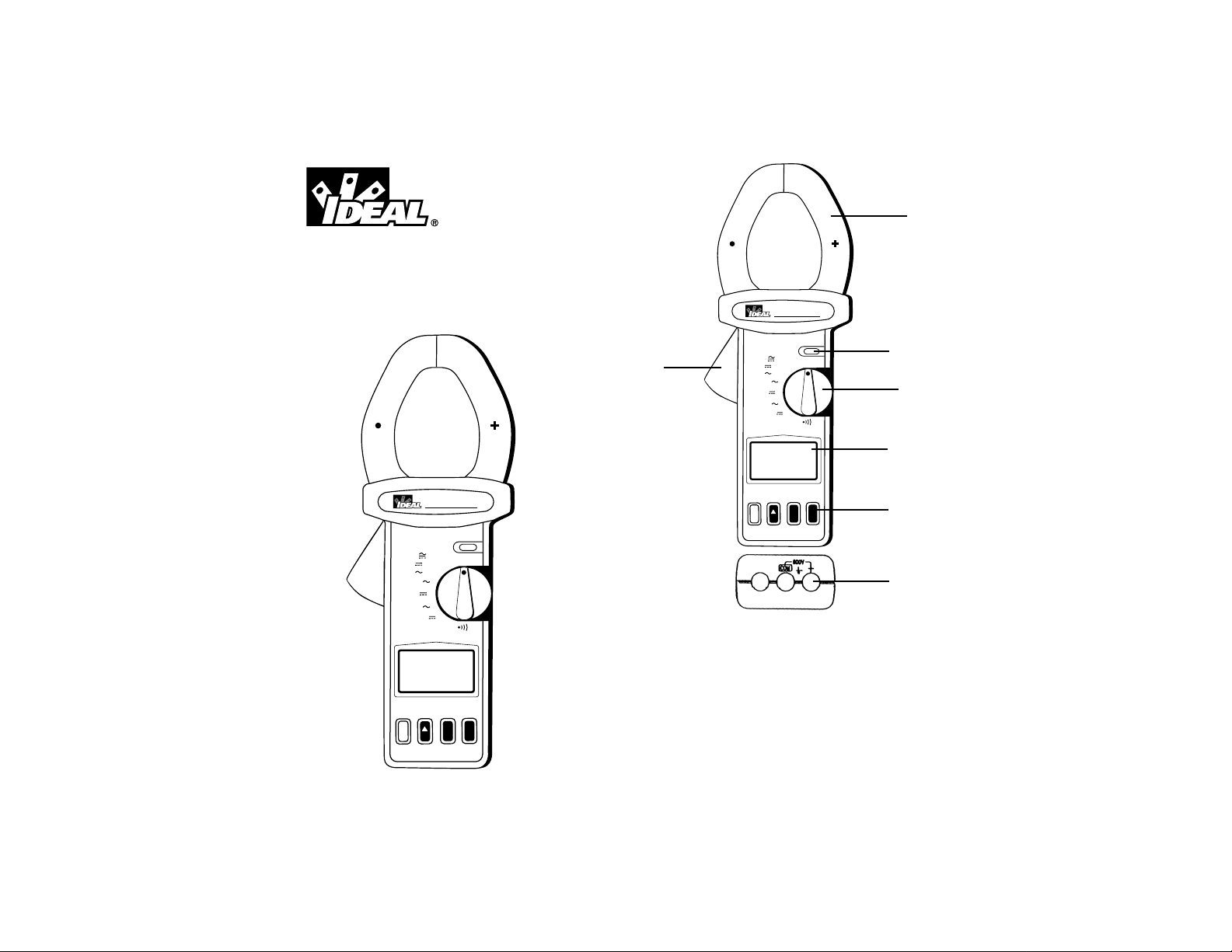
#61-800
800 Series
Power Clamp Meter
1. Transformer Jaw
2. Transformer Trigger
3. Data Hold Button
4. Rotary Function Switch
5. LCD Display
6. Function Buttons
7. Input Terminals
1
3
4
5
6
7
2
Power Clamp
V/A
KW
V
0
0
6
KW
V
0
5
2
V
V
A
A
°F
OFF
61-800
H
D
L
O
UTPUT 1m
O
1200KW
2500A
2100A
True RMS
DC
MIN
A/W
ZERO
CAT III - 600V
®
REL
MAX
RANGE
Page 2

4
Data Hold Button
• The data hold button is used to capture and hold a reading
on the LCD display.
• Press the button again to release the reading.
LCD Display
• 3-3/4 digit display with maximum indication of 3999.
• Function symbols, units, analog bargraph, low battery symbol, min/max symbols, relative symbol, and zero symbol are
included.
Function Buttons
DC A/W ZERO Button
• The DC A/W Zero button is used to zero out the DCA residual value.
• Press this button until the LCD displays a zero value and
the zero symbol.
• This button does not force the meter into manual range
mode.
• Press and hold the DC A/W Zero button for 2 seconds to
disable this function.
∆ REL Button
• The ∆ REL button captures the current reading and sets it
to zero to be used as a zero reference value for all subsequent measurements.
• Press this button until the LCD displays a zero value and
the
∆symbol.
• This function can also be used to offset the value caused by
the residual magnetism remaining in the core for DC current
or wattage measurements.
• This button will force the meter into manual range mode.
• The relative function will be disabled if the Min/Max function is enabled.
• Press and hold the
∆ REL button for 2 seconds to disable
this function.
3
WARNING!
1. DO NOT UNDER ANY CIRCUMSTANCES EXCEED THESE
RATINGS:
- Voltage is not to exceed 800 Volts.
- Wattage, Resistance and Continuity functions are not to
be performed on circuits capable of delivering greater than
600 Volts.
- Current measurements are not to be performed on circuits capable of delivering greater than 500 Volts
2. To avoid electrical shock hazards and/or damage to the
meter:
- Do not exceed the voltage ratings for the meter. Use
caution when measuring voltage.
- Do not use during electrical storms. AC power sources
with inductive loads or electrical storms may result in high
voltage. High energy transients can damage meter and present a dangerous shock hazard.
- Turn off power to the circuit or device being measured
before taking resistance and capacitance measurements.
Fully discharge all capacitors before measuring.
3. Ensure meter is in proper working order before using.
Visually inspect meter for damage. Performing a continuity
check can verify proper operation. If the meter reading goes
from overload to zero, this typically means the meter is in
proper working order.
4. Visually inspect leads for damage before using. Replace if
insulation is damaged or leads appear suspect.
5. Never ground yourself when taking electrical measurements.
Do not touch exposed metal pipes, outlets, fixtures etc.
Keep your body isolated from ground by using dry clothing,
rubber shoes, mats, or any other approved insulating material. Keep your fingers behind the finger guards on the
probes. Work with others.
6. Before beginning all unknown measurements, set meter to
highest possible range.
7. Before breaking a circuit for testing, turn off the power to the
circuit. When disconnecting from a circuit, disconnect the
hot lead first, then the common lead.
8. Disconnect the meter from the circuit before turning off any
indicator, including motors, transformers, and solenoids.
Page 3
65
MIN/MAX Button
• The Min/Max button is used to toggle between the minimum and maximum values captured by the clamp meter.
• Press once to display the minimum value.
• Press again to display the maximum value.
• Press a third time to return to normal measurement mode.
Range Button
• Pressing the range button enables manual ranging.
• While in manual range mode, pressing the range button
toggles between the ranges in the selected function.
• Press and hold the range button for 2 seconds returns the
meter to auto-ranging mode.
AC Current Measurements
AC Current Resolution Accuracy Accuracy
Range (50/60Hz) (40-1Khz)
400A 0.1A ±(1.5% +5) ±(2.0% +5)
1000A 1A ±(2.0% +5) ±(2.5% +5)
1000-2100A 1A ±(2.5% +5) ±(3.0% +5)
Overload Protection: 3000A
TRMS Measurements on AC Range
Accuracies specified at Crest Factor <3
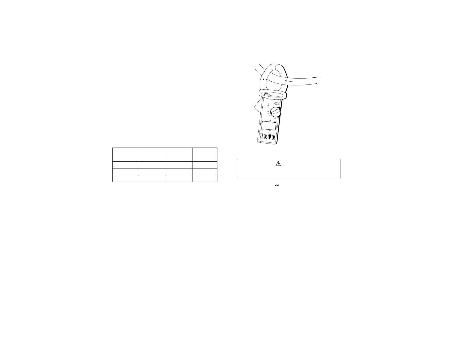
To Measure AC Current
1. Set rotary switch to A.
2. Using the trigger to open the jaws, fully enclose the conductor within the clamp.
3. Release the trigger and be sure that the jaws have closed
completely.
4. If the meter is in auto-ranging mode, the range will be automatically selected.
5. If the meter is in manual ranging mode, press the range button to select the desired range.
6. Measure AC current.
Warning
Make sure the test leads are disonnected prior to current
measurements.
A
6
1
-
8
0
0
P
o
w
e
r
C
la
m
p
O
U
TP
U
T
1m
V/A
H
O
L
12
D
00
K
W
25
0
0A
K
W
O
F
F
6
0
0
V
K
2
100
W
A
2
5
0
V
V
V
A
A
°F
T
r
u
e
R
M
S
D
C
A
/
W
Z
E
R
O
M
I
N
R
E
L
®
M
A
X
R
A
N
G
E
C
A
T
III - 6
00
V
Page 4

8
4. Release the trigger and be sure that the jaws have closed
completely.
5. If the meter is in auto-ranging mode, the range will be automatically selected.
6. If the meter is in manual ranging mode, press the range button to select the desired range.
7. Measure DC current.
Connecting to an Oscilloscope, Chart Recorder or
Data Logger
Current Range (AC, DC) Output Accuracy
0-400A 1mV/A ±(2.5% +0.5A)
400-2100A 1mV/A ±(2.5% +5A)
Overload Protection: 600VAC
7
DC Current Measurements
DC Current Resolution Accuracy
Range
400A 0.1A ±(1.5% +3)
2000A 1A
2000-2500A 1A + ±(2.0% +3)
Overload Protection: 3000A
To Measure DC Current
1. Set rotary switch to __A.
2. Push and hold the DCA Zero button until the reading shows
zero.
3. Using the trigger to open the jaws, fully enclose the conductor within the clamp.
Warning
Make sure the test leads are disconnected prior to current
measurements.
A
61-800
P
o
w
e
r
C
la
m
p
O
U
T
P
U
T
1m
V
/A
H
O
L
1
D
2
00
K
W
2
50
0A
K
W
O
F
F
60
0V
K
2
1
W
0
0
A
2
50
V
V
V
A
A
°F
T
r
u
e
R
M
S
D
C
A
/
W
Z
E
R
O
M
I
N
R
E
L
®
M
A
X
R
A
N
G
E
C
A
T
III - 6
0
0
V
T
U
O
0
0
12
0
250
0
210
True RMS
C
D
/W
A
R
E
Z
Power Clamp
1
T
U
P
W
K
A
A
E
R
O
T
CA
61-800
HOLD
/A
V
m
W
K
F
OF
V
0
60
W
K
250V
V
V
A
A
°F
N
I
M
®
L
X
A
M
ANGE
R
V
0
- 60
I
II
Page 5

5. If the meter is in manual ranging mode, press the range
button to select the desired range.
6. Measure AC voltage.
DC Voltage Measurements
DC Voltage Resolution Accuracy Input Impedance
Range
400mV 0.1mV ±(1.5% +3) 10M
4V 1mV 5M
40V 10mV
400V 100mV
600V 1V
Overload Protection:800V
To Measure DC Voltage
1. Set the rotary switch to __V.
2. Insert the black test lead into the COM terminal and the red
test lead into the + terminal.
3. Connect the test probes in parallel with the load or circuit.
4. If the meter is in auto-ranging mode, the range will be automatically selected.
5. If the meter is in manual ranging mode, press the range
button to select the desired range.
6. Measure DC voltage.
10
To Connect to a Monitoring Device
1. The analog output of the meter is proportional to the current
measurement (1mV/A).
2. Connect the monitoring device to the input terminals of the
power clamp meter. The red terminal is positive and the
black terminal is negative .
3. Connect these two terminals to an oscilloscope, chart
recorder or data logger to observe the wave form, or record
the data for future analysis.
AC Voltage Measurements
AC Voltage Resolution Accuracy Accuracy Input
Range (50/60Hz) (40-1kHz) Impedance
4V 1mV ±(1.5% +5) ±(2.0% +5) 5M
40V 10mV
400V 100mV
600V 1V
Overload Protection: 800V
TRMS Measurements on AC Range
Accuracies specified at Crest Factor <3
To Measure AC Voltage
1. Set the rotary switch to __V.
2. Insert the black test lead into the COM terminal and the red
test lead into the + terminal.
3. Connect the test probes in parallel with the load or circuit.
4. If the meter is in auto-ranging mode, the range will be automatically selected.
9
Page 6

12
Temperature Measurement
Temperature Range Resolution Accuracy
-50 to –400°F 0.1°F ±(1% +3)
-400 to 1000°F 1°F
Overload Protection: 600VAC
To Measure Temperature
1. Turn the rotary switch to °F.
2. Connect the adapter with the – side into the COM terminal,
and the + side into the + terminal. (61-XXX; not supplied)
3. Insert the K type thermocouple into the adapter. (61-XXX;
not supplied)
4. If the meter is in auto-ranging mode, the range will be automatically selected.
5. If the meter is in manual ranging mode, press the range button to select the desired range.
6. Measure temperature
Resistance and Continuity Measurement
Resistance Resolution Accuracy Audible
Range Continuity
40-400Ω 0.1Ω ±(1% + 2) <40__
Open voltage 0.4V
AC+DC Watt Measurement
AC+DC Watt Range Resolution Accuracy
(250V max)
40kW 0.01kW ±(2.5% +5)
400kW 0.1kW
AC+DC Watt Range Resolution Accuracy
(600V max)
400kW 0.1kW ±(2.5% +5)
1200kW 1kW
Overload Protection: 600VAC
To Measure AC+DC Watts
1. Set the rotary switch to KW/600V or KW/250V.
2. Push and hold the DCA Zero button until the reading shows zero.
3. Insert the black test lead into the COM terminal and the red
test lead into the + terminal
4. Connect the test leads to the circuit with the black lead to
neutral, and the red lead to the active line.
5. Clamp around the active line.
6. If the meter is in auto-ranging mode, the range will be automatically selected.
7. If the meter is in manual ranging mode, press the range button
to select the desired range.
8. Measure AC+DC Watts
11
61-800
Power Clamp
HOLD
A
/
V
m
1
T
U
P
T
U
O
W
K
0
0
12
W
K
F
OF
A
0
250
V
0
60
W
K
250V
A
0
210
V
V
A
A
°F
True RMS
C
D
N
I
M
®
W
/
A
L
E
R
X
A
M
NGE
A
R
O
R
E
Z
V
0
- 60
I
I
I
T
CA
Page 7

14
Battery Replacement
1. Turn the power off and remove the test leads from the clamp
meter.
2. Remove the screws from the back case.
3. Lift and remove the back case.
4. Remove the old battery and insert a new 9V battery.
5. Replace the back case, and secure the case screws.
To Measure Resistance and Continuity
1. Set the rotary switch to .
2. Insert the black lead into the COM port and the red lead into
the port.
3. Connect the test leads to the circuit to be measured
4. Measure resistance.
5. If the resistance is lower than 40Ω, the meter beeps.
General Specifications
Indoor Use
Conductor Size: Cable 55mm (approx.)
Bus Bar 65mm (D) x 24mm (W)
Battery Type: 9V
Display: 3-3/4 LCDwith 40 seg. bargraph
Range Selection: Auto and manual
Overload Indication: Left most digit blinks
Power Consumption: 12mA (approx.)
Low battery Indication:
Sampling Time: 2 times/sec. (display)
20 times/sec. (bargraph)
Operating Temperature: 4°C to 50°C
Operating Humitdity: Less than 85% relative
Altitude: Up to 2000M
Storage Temperature: -20°C to 60°C
Storage Humidity: Less than 75% relative
Dimension: 271mm (L) x 112mm (W) x 46mm (H)
10.7” (L) x 4.4” (W) x 1.8” (H)
Weight: 647 g/22.8 oz. (batteries included)
Accessories: Carrying bag x 1
Users manual x 1
9v battery x 1, installed
Options: Thermal couple adapter
K-type thermal couple
Maintenance
13
Warning
To avoid electrial shock, remove test leads before opening the
cover. Repairs or servicing not covered in this manual
should only be performed by qualified personnel.
Warning
Do not touch or adjust any components inside the clamp
when the back case is removed.
Page 8

15
Lifetime Limited Warranty
This meter is warranted to the original purchaser against
defects in material or workmanship for the lifetime of the meter.
During this warranty period, IDEAL INDUSTRIES, INC. will, at
its option, replace or repair the defective unit, subject to verification of the defect or malfunction.
This warranty does not apply to defects resulting from abuse,
neglect, accident, unauthorized repair, alteration, or unreasonable use of the instrument.
Any implied warranties arising out of the sale of an IDEAL
product, including but not limited to implied warranties of merchantability and fitness for a particular purpose, are limited to
the above. The manufacturer shall not be liable for loss of use
of the instrument or other incidental or consequential damages,
expenses, or economic loss, or for any claim or claims for
such damage, expenses or economic loss.
State laws vary, so the above limitations or exclusions may not
apply to you. This warranty gives you specific legal rights, and
you may also have other rights which vary from state to state.
IDEAL INDUSTRIES, INC.
Sycamore, IL 60178, U.S.A.
800-304-3578 Customer Assistance
www.testersandmeters.com
ND 2353-1 Made in Taiwan
 Loading...