

Page 1
2
#61-494
#61-495
49 0 Series
Industrial Grade Multimeter
1
3
2
4
5
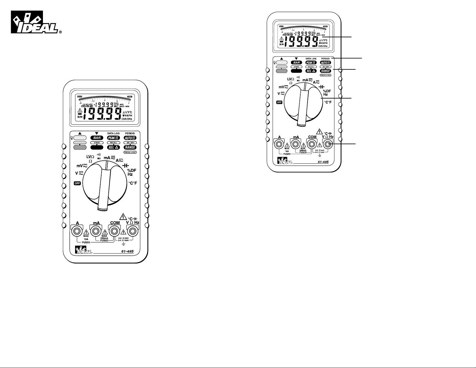
1. LCD Display
2. Function Buttons
3. Data Log Features
4. Rotary Function Switch
5. Input Connectors
WARNING!
1. DO NOT UNDER ANY CIRCUMSTANCES EXCEED THESE RATINGS:
- Voltage is not to exceed 1000 Volts.
- Resistance, Capacitance, Logic and Continuity functions are not to be performed on circuits
capable of delivering greater than 600 Volts.
- Current measurements are not to be performed on circuits capable of delivering greater than
500 Volts
True RMS
Data Logging
M/M/A
True RMS
Data Logging
M/M/A
Page 2
43
Auto Hold Button
• The auto hold button toggles the auto hold function on or off.
• Place the meter in manual range mode to activate this
feature.
• Auto hold is activated when the first stable reading is achieved.
• When activated, the meter beeps when the reading is updated, and it is displayed in the sub-display with
annunciator.
• This function is not available on the 2GΩ range.
Blue Button
• The blue button toggles between the black and blue functions on the dial.
M/M/A Button
• The M/M/A button toggles between the stored minimum, maximum and average values captured during
peak hold.
• The MIN/MAX/AVG value is displayed in the sub-display with the appropriate annunciator.
• To escape this function, press the M/M/A button for 2 seconds.
• Pressing the M/M/A button for > 2 seconds prior to entering M/M/A mode enables the store function.
Store Function
• Press the M/M/A button for 72 seconds to enter the store function.
• Pressing the M/M/A key in store mode stores the displayed measurement into the memory.
• Up to 1000 data points can be stored into memory for future analysis.
• When memory is full, the meter will beep twice after each key press.
• Pressing the range button for > 2 seconds exits store mode and returns to normal measurements.
REL Button
• This function displays the differential between the measurement and a stored value.
• The displayed measurement is stored in memory when this function is activated.
• This value is displayed in the sub-display with the annunciator.
• All new measurements will be subtracted from the stored value, and the difference will be displayed in
the main display.
• Pressing the REL for > 2 seconds enables the recall function.
Recall Function
• In recall mode, use arrow keys, ▲ ▼, above the light and bar buttons to scroll through the stored readings.
• Press and hold the arrow keys to scroll faster (10 data points/second)
• Press the REL button for > 2 seconds to exits recall function and returns to normal measurements.
2. To avoid electrical shock hazards and/or damage to the meter:
- Do not exceed the voltage ratings for the meter. Use caution when measuring voltage.
- Do not use during electrical storms. AC power sources with inductive loads or electrical storms may
result in high voltage. High energy transients can damage meter and present a dangerous shock hazard.
- Turn off power to the circuit or device being measured before taking resistance and capacitance
measurements. Fully discharge all capacitors before measuring.
3. Ensure meter is in proper working order before using. Visually inspect meter for damage. Performing a
continuity check can verify proper operation. If the meter reading goes from overload to zero, this
typically means the meter is in proper working order.
4. Visually inspect leads for damage before using. Replace if insulation is damaged or leads appear suspect.
5. Never ground yourself when taking electrical measurements. Do not touch exposed metal pipes, outlets,
fixtures etc. Keep your body isolated from ground by using dry clothing, rubber shoes, mats, or any
other approved insulating material. Keep your fingers behind the finger guards on the probes. Work
with others.
6. Before beginning all unknown measurements, set meter to highest possible range.
7. Before breaking a circuit for testing, turn off the power to the circuit. When disconnecting from a circuit,
disconnect the hot lead first, then the common lead.
8. Disconnect the meter from the circuit before turning off any indicator, including motors, transformers and
solenoids.
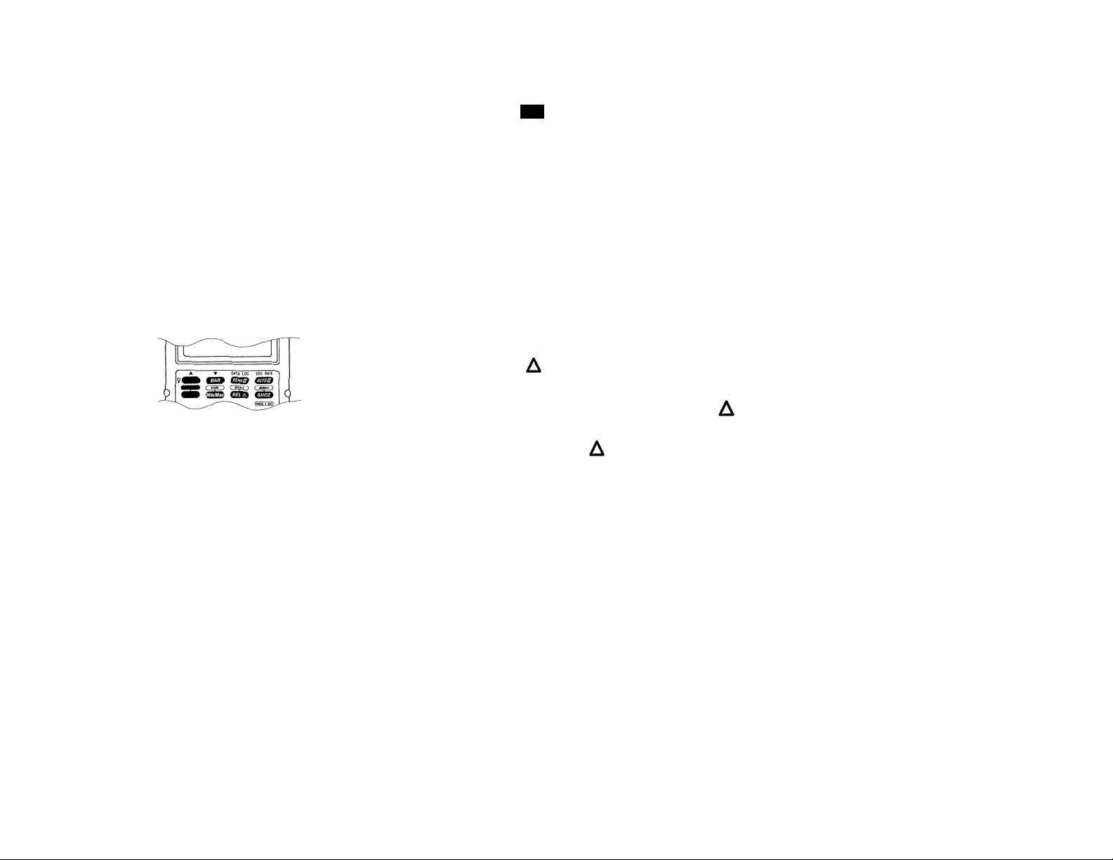
Function Buttons
The meter beeps once for every valid key-press, and beeps twice for every invalid key-press.
Backlight Button
• The light button is used to turn the backlight on or off.
• This function is disabled in DATA LOG mode.
BAR Button
• The bar button toggles the analog bar graph between left justified and zero centered.
• Available for DC voltage and current measurements only.
• This function is disabled in DATA LOG mode.
Peak Hold Button
• The peak hold button toggles the peak hold function on or off.
• The beeper sounds when a new minimum or maximum value is detected.
AH
Page 3

6
Data Log Functions (continued)
Data log-in
A. Press the Peak Hold button for > 2 seconds while in data logging mode enables the data log-in func-
tion.
B. The meter begins storing data points into memory according to the selected log rate.
C. Pressing the Peak hold button while in the mode interrupts data log-in for log-rate resetting. “PAUS”
is displayed on the secondary menu while the data flow is interrupted.
D. While data is being stored into memory, “-“ is shown on the secondary display.
E. When 40K data points have been stored, the data log-in stops, the bar is full, the “-“ begins blinking,
and FULL is displayed on the secondary display.
Log Rate Function
Press the auto hold button while in data logging mode to select the log rate.
Select from 0.5”, 1”, 10”, 30”, 60”, 120”, 180”, 240”, 300”, 360”, 480”, and 600”.
Press the auto hold button to escape and return to data logging mode.
Overload Protection
Function Overload Protection
VAC & VDC 1000V
AAC & ADC 1A/500V
10A/500V
Ohms (Ω) 600VAC/600VDC
Diode 600VAC/600VDC
Continuity 600VAC/600VDC
Unit of Measure Multipliers
For your reference, the following symbols are often used to make measurement easier:
Symbol
Verbal Multiplier
M mega x 1,000,000
K kilo x 1,000
m milli ÷ 1,000
µ micro ÷1,000,000
Additional Features
Auto fuse detection: The meter checks the integrity of the internal fuses for the mA and A measurements.
Probe input guard: The meter beeps continuously and displays “ProbE” if a probe is inserted in a current
input connector for other measurement functions.
Buzzer: A single beep indicates correct operation; two beeps indicate a warning or error condition.
Peak Hold: ±(0.7% +20) additional error for > 20% of full scale and pulse width greater than 0.5mS;
±(10% +20) additional error for > 50% of full scale on 2V range.
5
Range Button
• Pressing the range button for 2 seconds toggles the meter between auto and manual ranging mode.
• When in manual range mode, pressing the button changes the measurement range.
• Pressing the range button while in AC voltage measurements for > 2 seconds enables the dB/dBm function.
• While in dB/dBm mode, pressing the range button toggles between dB and dBm.
dB/dBm Function
• The reading of dB or dBm appears on the secondary display.
• The reference resistance reading for dBm is 600Ω_and the reference voltage for dB is 1V.
• Pressing the range button for > 2 seconds exits dB/dBm mode and returns to AC voltage measurements.
Data Log Features
The range button and the M/M/A are the only buttons enabled in data logging mode. All other buttons perform the data logging functions labeled in red directly above the button. The auto power off function is also
disabled.
Press the blue button for > 2 seconds to enter data logging mode. Changing the rotary function switch
escapes data logging mode without storing data to memory. Pressing the blue button while in data logging
mode returns to normal measurements.
Data quantities (61-495): 40K readings form as sequence number on sub-display up to 9999 and each 1
⁄4 scale of bar indicates 10K. (61-494) 6K readings form as sequence number on sub-display up to 6000.
Max pause time: 4095 seconds; exceeding the maximum pause times stores data as 4095 seconds.
Max pause and log rate: 3.6k
▲ ▼ Functions
While in data logging mode, the light button and bar button scroll up and down through the data logging
menu selections.
Data Log Functions
Data log-out
A. Press the Peak Hold button while in data logging mode enables the data log-out function.
B. The first data displayed is the last data point logged in.
C. Pressing the ▲ ▼ buttons scrolls up and down through the data.
D. Pressing the ▲ ▼ buttons for > 2 seconds scrolls up and down through the data at a rate of 10 data
points/seconds, and stops at the reading when the button is released.
E. Pressing the M/M/A button while in this mode toggles between the maximum and minimum values
logged into memory. Pressing for > 2 seconds escapes.
F. Pressing the range button while in this mode toggles the turning points logged-in with “MAX” or
“MIN” symbol depending on the comparison from the current reading and the next reading. Press the
range key again to escape.
Page 4

87
AC Frequency Resolution Accuracy Accuracy
Voltage Range (61-494) (61-495)
20mV 40 ~ 100Hz 1µV ±(0.7% +80) ±(0.7% +80)
100 ~ 1kHz ±(1.0% +80) ±(1.0% +80)
200mV 40 ~ 100Hz 10µV ±(0.7% +80) ±(0.7% +80)
100 ~ 1kHz ±(1.0% +80) ±(1.0% +80)
2V 40 ~ 100Hz 100µV ±(0.7% +50) ±(0.7% +50)
100 ~ 1kHz ±(1.0% +50) ±(1.0% +50)
1k ~ 10kHz ±(2.0% +60) ±(2.0% +60)
10k ~ 20kHz ±(3.0% +70) ±(3.0% +70)
20k ~ 50kHz ±(5.0% +80) ±(5.0% +80)
50k ~ 100kHz ±(10.0% +100) ±(10.0% +100)
20V 40 ~ 100Hz 1mV ±(0.7% +50) ±(0.7% +50)
100 ~ 1kHz ±(1.0% +50) ±(1.0% +50)
1k ~ 10kHz ±(2.0% +60) ±(2.0% +60)
10k ~ 20kHz ±(3.0% +70) ±(3.0% +70)
20k ~ 50kHz ±(5.0% +80) ±(5.0% +80)
50k ~ 100kHz ±(10.0% +100) ±(10.0% +100)
200V 40 ~ 100Hz 10mV ±(0.7% +50) ±(0.7% +50)
100 ~ 1kHz ±(1.0% +50) ±(1.0% +50)
1k ~ 10kHz ±(2.0% +60) ±(2.0% +60)
10k ~ 20kHz ±(3.0% +70) ±(3.0% +70)
20k ~ 50kHz ±(5.0% +80) ±(5.0% +80)
750V 40 ~ 100Hz 10mV ±(0.7% +50) ±(0.7% +50)
100 ~ 1kHz ±(1.0% +50) ±(1.0% +50)
Auto power off: The meter turns itself off within 30 minutes if no controls or settings are changed.
Restore power by switching dial.
Power-up Options: Press button while turning meter on from OFF position.
Light button: Disable backlight auto off
Range button: Turn off buzzer
Blue button: Disable Auto Power Off
Auto H: Set temperature measurement default as °F
M/M/A: Clear memor y area for storage
Voltage Measurements (DC, AC, AC+DC)
DC Voltage Resolution Accuracy Accuracy
(61-494) (61-495)
20mV 1µV ±(0.06% +60) ±(0.06% +60)
200mV 10µV ±(0.06% +20) ±(0.06% +20)
2V 100µV ±(0.06% +10) ±(0.06% +10)
20V 1mV
200V 10mV
1000V 100mV
dBm (typical): -15dBm ~ 55dBm (0dBm = 1mW
into 600Ω)
dBm (typical): -80dBV ~ 50dBV = 1VRMS)
Input Impedance: 10MΩ, <100pF
Overload Protection: 1000VDC, 750VRMS
AC Conversion Type: AC Coupled, True RMS responding
AC+DC Volts: Same as ACVRMS +1.00% + 8 digits
Crest Factor: +1.5% addition error for C.F. from 1.4 ~ 3
+3.0% addition error for C.F. from 3 ~ 4
Page 5

9
To Measure Voltage:
1. Plug the Black test lead into the COM port and the Red test lead into the VΩHz port.
2. Set the rotary switch to either the V or mV position.
3. Push the blue button to choose between DC, AC, or AC+DC measurements.
4. Connect the meter in parallel with the load or circuit.
5. Measure the voltage
6. The AC and AC+DC measurements provide a True RMS measurement.
7. For AC Measurements, the frequency of the measured signal > 20% of full scale is displayed on the secondary display.
Current Measurements (DC, AC, AC+DC)
DC Current Resolution Accuracy Accuracy
Range (61-494) (61-495)
20mA 1µA ±(0.3% +40) ±(0.2% +40)
200mA 10µA
2A 100µA ±(0.3% +40) ±(0.2% +40)
10A 1mA
AC Current Frequency Resolution Accuracy Accuracy
Range Range (61-494) (61-495)
20mA 40Hz ~ 500Hz 1µA
±(0.8% +50) ±(0.8% +50)
500Hz ~ 1kHz ±(1.2% +80) ±(1.2% +80)
200mA 40Hz ~ 500Hz 10µA
±(0.8% +50) ±(0.8% +50)
500Hz ~ 1kHz
±(1.2% +80) ±(1.2% +80)
1kHz ~ 3kHz
±(2.0% +80) ±(2.0% +80)
2A 40Hz ~ 500Hz 100µA
±(0.8% +50) ±(0.8% +50)
500Hz ~ 1kHz
±(1.2% +80) ±(1.2% +80)
10A 40Hz ~ 500Hz 1mA
±(0.8% +50) ±(0.8% +50)
500Hz ~ 1kHz
±(1.2% +80) ±(1.2% +80)
1kHz ~ 3kHz
±(2.0% +80) ±(2.0% +80)
Voltage Burden: 800mV max. for mA input; 1V max. for A input.
Input Protection: Equipped with high energy fuse.
1A, 600V, IR 10kV fuse for mA input
15A, 600V, IR 100kV fuse for A input.
AC Conversion Type: AC Coupled, True RMS responding
AC+DC Volts: Same as ACVRMS +1.00% + 8 digits
Crest Factor: +1.5% addition error for C.F. from 1.4 ~ 3
+3.0% addition error for C.F. from 3 ~ 4
To Measure Current:
1. Plug the Black test lead into the COM port and the Red test lead into the mA or A port.
2. Set the rotary switch to either the mA or A position.
3. Push the blue button to choose between DC, AC, or AC+DC measurements.
4. Connect the meter in series with the load or circuit.
5. Measure the current.
6. The AC and AC+DC measurements provide a True RMS measurement.
7. For AC Measurements, the frequency and period of the measured signal are displayed on the secondary
displays.
10
Warning
Limit large current measurements (10~20A to 30 seconds,
and allow two minutes of cooling between readings.
Do not connect to circuits with >600V.
Page 6
Resistance and Low Voltage Resistance Measurements (Ohms)
Resistance Resolution Accuracy Accuracy
Range (61-494) (61-495)
200Ω 10mΩ ±(0.3% +30) ±(0.3% +30)
2kΩ 100mΩ
20kΩ 1Ω
200kΩ 10Ω
2MΩΩ 100Ω ±(0.3% +50) ±(0.3% +50)
20MΩ 1kΩ ±(5.0% +50) ±(5.0% +50)
200MΩ 10kΩ ±(5.0% +20 ±(5.0% +20)
2GΩ 100kΩ ±(5.0% +8) ±(5.0% +8)
Low Voltage Resolution Accuracy Accuracy
Resistance (61-494) (61-495)
Range
2kΩ 100mΩ ±(0.6% +20) ±(0.6% +30)
20kΩ 1Ω
200kΩ 10Ω
2MΩ 100Ω ±(0.6% +50) ±(0.6% +50)
20MΩ 1kΩ ±(7.0% +50) ±(7.0% +50)
200MΩ 10kΩ ±(7.0% +20) ±(7.0% +20)
Open circuit voltage: 3.3V
Open circuit low voltage: 0.6V
Input protection: 600V rms
To Measure Resistance:
1. Turn the power off to the circuit or device that is to be measured and discharge all capacitors before
attempting a measurement.
2. Plug the Black test lead into the COM port and the Red test lead into the VΩHz port.
3. Set the rotary switch to the Ω LV Ω position.
4. Press the blue button to choose between Ω and LVΩ.
LV setting reduces the maximum test voltage level to about 0.5V to avoid turning on semiconductor devices.
11
Frequency and Duty Factor Measurements
Freqency Resolution Accuracy Accuracy
Range (61-494) (61-495)
20Hz 0.001Hz ±(0.01% +50) ±(0.01% +50)
200Hz 0.01Hz ±(0.01% +10) ±(0.01% +10)
2kHz 0.1Hz
20kHz 1Hz
200kHz 10Hz
1MHz 100Hz
Duty Factor Resolution Accuracy Accuracy
(61-494) (61-495)
20% ~ 80% 0.1% +6 digits +6 digits
Sensitivity: 0.5Vp-p for 15Hz ~ 1MHz
1Vp-p for 1 MHz ~ 4MHz
Min. frequency: 5Hz
Input protection: 600V rms
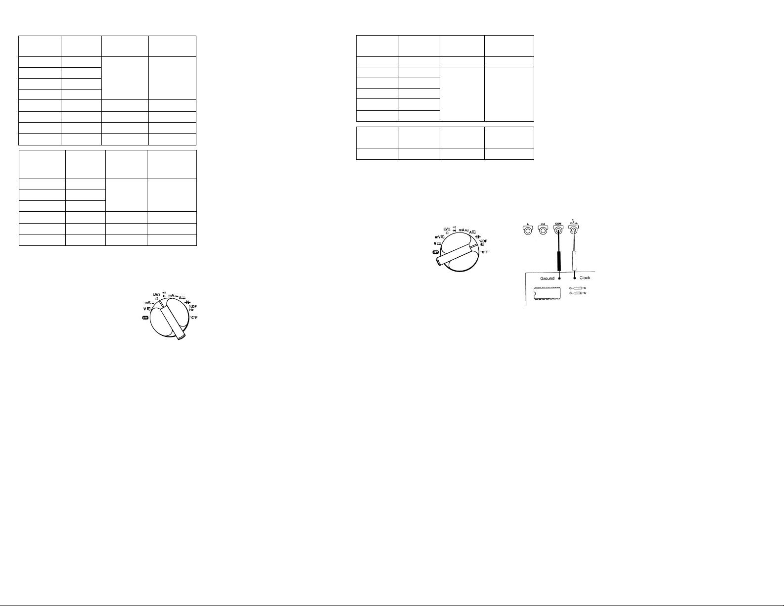
To Measure Frequency:
1. Plug the black test lead into the COM port and the red test lead into the VΩHz port.
2. Set the rotary switch to the Hz %DF position.
3. For duty factor, push the blue button until % is shown on the main display, and Hz is shown in the upper
right secondary display.
4. Connect the meter in parallel with the load or circuit.
5. Measure frequency or duty factor.
Duty factor is the percentage of the signal that is high
12
Page 7

13
Capacitance Measurements
Range Resolution Accuracy Accuracy
(61-494) (61-495)
4nF 1pF ±(1.9% +10) ±(1.5% +10)
40nF 10pF
400nF 100pF ±(1.4% +5) ±(0.9% +5)
4µF 1nF
40µF 10nF ±(1.7% +5) ±(1.2% +5)
400µF 100nF
4mF 1µF ±(2.0% +5) ±(1.5% +5)
10mF 10µF
To Measure Capacitance:
1. Turn the power off to the circuit or device that is to be measured and discharge all capacitors before
attempting a measurement.
2. Plug the Black test lead into the COM port and the Red test lead into the VΩHz port.
3. Set the rotary switch to the __ position.
4. Measure capacitance.
Temperature Measurements
Temperature Resolution Accuracy Accuracy
Range (61-494) (61-495)
-200°C ~ -100°C 0.1°C ±(0.1% +6°C) ±(0.1% +6oC)
-100°C ~ 1200°C 1°C ±(0.1% +3°C) ±(0.1% +3oC)
To Measure Temperature
1. Plug the temperature probe and adapter into the COM the VΩHz port.
2. Set the rotary switch to the °C °F position.
3. For correct reading, ensure that the device being tested contains no voltage.
4. Press the blue button to chose between a °C or °F display.
Multiply the accuracy by 2 for °F
Input protection: 600V rms
Note: The readings <360°C on 1°C resolution range when settled as manual range, display reads “Er” to
change to lower range for best measurements.
Diode Testing
Diode Check:
To ensure a proper functioning diode, the meter will develop a voltage across the component from a test
current. The diode test function allows measurements of forward voltage drops across diode and transistor
junctions.
1. Turn off power to the device or circuit that is being tested and discharge all capacitors.
2. Plug the Black test lead into the COM port and the Red test lead into the VΩHz port.
3. Set the rotary switch to the position.
4. Press the blue button until is shown on the display
5. Connect the test leads to the diode.
Forward bias: Good = 0.4 to 0.9V
Bad = 0 or ≥ 2.0V
Reverse bias: Good = OL
Bad = <2.0V
Test current: 1.1mA (typical)
Open circuit voltage: 3.3VDC (max)
Input Protection: 600V rms
14
Page 8

General Specifications
V connector: 1100 Vp AC+DC
850 Vp m m AC+DC
LVΩΩ• )( Hz% DF °C°F
Temperature coefficient: 0.1 X (Spec. Accuracy) per °C, <18°C or >28°C
Battery Life: 100 hours typical (alkaline)
Physical Characteristics
Dimensions: 200mm x 90mm x 42mm
212mm x 100mm x 55mm (w/holster)
Weight (w/battery): 0.4Kg
Weight (w/holster): 0.6Kg
Enviornmental Characteristics
Temperature Operating: 0 to +50°C
Temperature Non-Operating: -20 to +60°C
Humidity (Operating): <80% R.H.
Altitude (Operating): 2,222m (7290 ft.)
Altitude (Non-Operating): 12,300m (40354 ft.)
Vibration & Shock (Operating): MIL-T-28800E Type II Class 5
2.66g RMS, 5 to 500 Hz,
3 axes, (10 min. each)
Dust/Water Protection IP Rating: IP 64
Certifications & Compliances
Safety: Designed to IEC 1010-1, UL3111 and CSA
Specifications Input Rating: 1000VDC Category II
600VDC Category III
750VAC Category II
600VAC Category III
Overvoltage Category: Cat III: Distribution level mains, fixed installations
Cat II: Local level mains, appliances, portable equipment
Cat I: Signal level, special equipment or parts of equipment,
telecommunication, electronics
Pollution Degree 2: Do not operate in environments where conductive pollutants may be
present.
16
15
Continuity Check
To Verify Continuity:
A continuity test ensures that all circuit connections
are intact.
1. Plug the Black test lead into the COM port and the Red test lead into the VΩHz port.
2. Set the rotary switch to the position.
3. Press the blue button until is shown in the display.
4. Connect the test leads to the circuit to be measured. The buzzer will sound if the resistance of the circuit
measured is lower than 50Ω.
Continuity threshold: Approx. 50Ω
Continuity Indicator: 2kHz tone buzzer
Input protection: 600V rms
General Specifications
Stated accuracies are at 23°C +5°C at less than 80% RH and without battery indicator displayed.
LCD display digits: 4-1/2 or 3-3/4
Bargraph segements: 42 segment graph
Display count 20,000 or 4,000
Numeric update rate: 2 times/sec (20,000 count)
Bargraph: 20 times/sec
Polarity display: Automatic
Overrange display: OL is displayed
Low voltage indicator: is indicator
Automatic power-off time: Automatic backlit off = 15 minutes
Power source One 9V dr y cell batter y
Maximum input voltage: 1000V (750VAC) Cat II between V and COM
Maximum floatin voltage: 1000V (750VAC) Cat IIbetween any terminal and earth ground
Maximum input current: 200mA between mA and COM 10A continuous between A and COM
(20A for 30 seconds)
Maximum open circuit 600V between A and COM and
Voltage (current inputs): between mA and COM
Overload protection mA 1A (600V)fast blow fuse connector:
A connector: 15A (600V) fast blow fuse
CUS
Page 9
1817
Maintenance
Battery Installation or Replacement:
1. The #61-492 is powered by one 9 volt battery.
2. Remove the test leads from the front terminals and turn the meter off.
3. Remove the screw from the battery cover and lift to remove.
4. Replace batteries.
5. Make sure the battery box leads do not become pinched between the case and batter y cover before
replacing the battery cover and screw.
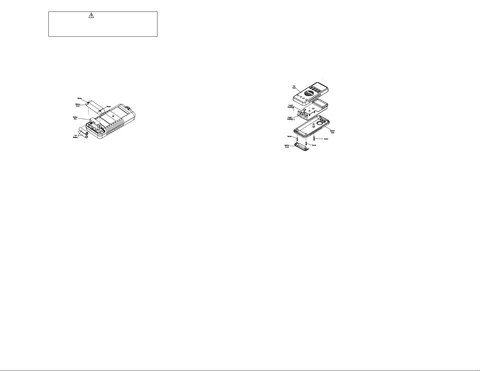
Fuse Replacement
1. Remove the test leads from the front terminals and turn the meter off.
2. Remove the screw from the battery cover and lift to remove.
3. Remove the battery.
4. Remove the three screws connecting the top and bottom cases of the meter.
5. Separate the top case and PCB of the meter.
6. Replace the fuse (Fuse 1 or Fuse 2)
7. Re-assemble the top case and PCB of the meter
8. Assemble the top case, PCB and bottom case of the meter.
9. Re-install the battery and batter y cover.
Warning
To avoid electrical shock, remove test lead before opening the
cover. Repairs or servicing not covered in this manual
should only be performed by qualified personnel.
Page 10

IDEAL INDUSTRIES, INC.
Sycamore, IL 60178, U.S.A.
800-304-3578 Customer Assistance
www.testersandmeters.com
ND 2351-1 Made in Taiwan
19
Lifetime Limited Warranty
This meter is warranted to the original purchaser against defects in material or workmanship for the lifetime of
the meter. During this warranty period, IDEAL INDUSTRIES, INC. will, at its option, replace or repair the defective unit, subject to verification of the defect or malfunction.
This warranty does not apply to defects resulting from abuse, neglect, accident, unauthorized repair, alteration,
or unreasonable use of the instrument.
Any implied warranties arising out of the sale of an IDEAL product, including but not limited to implied warranties of merchantability and fitness for a particular purpose, are limited to the above. The manufacturer shall
not be liable for loss of use of the instrument or other incidental or consequential damages, expenses, or economic loss, or for any claim or claims for such damage, expenses or economic loss.
State laws vary, so the above limitations or exclusions may not apply to you. This warranty gives you specific
legal rights, and you may also have other rights which vary from state to state.
 Loading...