

Page 1
2
#61-152
#61-153
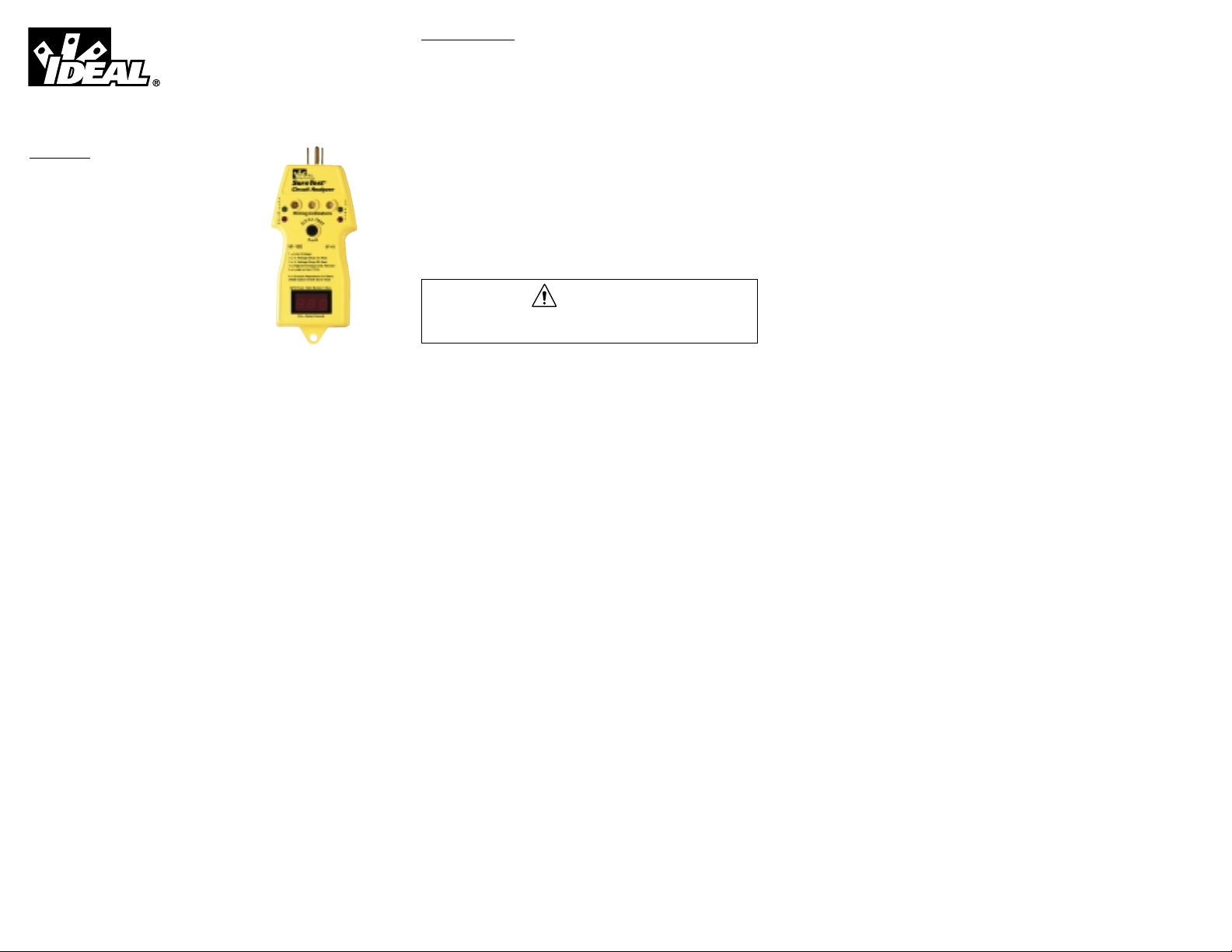
SureTest®Model ST 1D Instructions
Introduction
The SureTest®family of circuit analyzers identify
problems common to electrical circuits quickly,
easily and accurately. They have a patented
voltage drop test, which applies a full 15 ampere
load without causing interruption to equipment
on the circuit.
Product Features
• Identifies and Locates
Loose Wire Connections
Bad Splices/Receptacles
High Resistance Grounds
False (Bootleg) Grounds
Shared Neutrals
• Verifies
Proper Wiring in 3-Wire Receptacles
Proper GFCI Operation
Dedicated Circuit Presence
Isolated Ground Presence (with the 61-176 Isolated Ground Adapter)
• Measures
Line Voltage
Ground Impedance
% Voltage Drop by Conducting an Actual Full 15 Amp Load Test
% Voltage Drop by Simulating a 20 Amp Load Test
GFCI Trip Time
Neutral-to-Ground Voltage
Estimated Load on Circuit
General Operation
The SureTest®Model ST-1D Circuit Analyzer takes only seconds to test each
outlet and circuit under a full load. The ST-1D indicates proper wiring, voltage drop and line voltage in an easy pass/fail format. A simple programming menu gives access to measurements of line voltage, voltage drop at a
full 15 amperes and 20 amperes, ground-to-neutral voltage, estimated load
on the circuit and ground impedance. The ground fault circuit interrupter
(GFCI) test is performed separately and will disrupt the electrical supply if a
functional GFCI is present.
Any discrepancies from a normal reading indicates that a problem
has been detected in the circuit.
For use in 3-prong (grounded) outlets, inset the ST-1D into the receptacle
with the ground pin extended. For use in 2-prong (non-grounded) outlets,
leave the ground pin retracted. Non-grounded (2-prong) outlets will be
tested for voltage drop and line voltage only.
WARNING
Do not use on outputs from UPS systems, light dimmers or square
wave generating equipment.
Insert the unit in the receptacle, observe test results, remove and reinsert the
unit while pressing the test button to perform the ground impedance test,
and then move on to the next receptacle. Allow at least 20 seconds
between insertions. Repeatedly inserting the SureTest into a receptacle will
exceed its ability to dissipate heat within the unit, resulting in fluctuating
readings or damage to the unit.
False Ground Indication
Sometimes 2-wire receptacles are replaced with 3-wire receptacles to
accommodate 3-wire plugs. A short placed between ground and neutral on
the back of the receptacle will test and appear to be a normal 3-wire circuit.
Common receptacle testers will test this configuration as a normal 3-wire
outlet.
Display of "FG" on the LED display on power-up indicates a suspected false
ground. False ground is defined as a short between the ground and neutral
wires very close to the receptacle. A false ground may also be indicated if
the receptacle is within 15 feet of the neutral-ground bonding point at the
panel, or if conduit is being used as the ground conductor.
Page 2
4
Specifications
Case Construction: GE Cycolac molded plastic
Operating Range: 108 to 132 Volts (61-152)
207 to 253 v. (61-153)
Power Consumption: 1 Watt contin; 1800 W peak
Wiring Indications: Pass/Fail format.
Digital Display: Seven segment L.E.D., .3”
Operating Temp.: 0 C to 50 C
Storage Temp.: -20 C to +65 C
Dimensions: 17.78 x 7.62 x 3.81 cm
Weight: 200 grams (7 ounces)
Accuracy
Line Voltage: ±2.5% full scale ±1 digit
Voltage Drop: ±2.5% full scale ±1 digit
Ground-to-Neutral Voltage: ±2.5% full scale ±1 digit
Est. Load on Circuit: ±10% full scale ±1 digit
Ground Impedance: ±2.5% full scale ±1 digit (0-1 Ohm)
±5.0% full scale ±1 digit (1-2 Ohm)
GFCI Trip Time: ±2.5” full scale ±1 digit
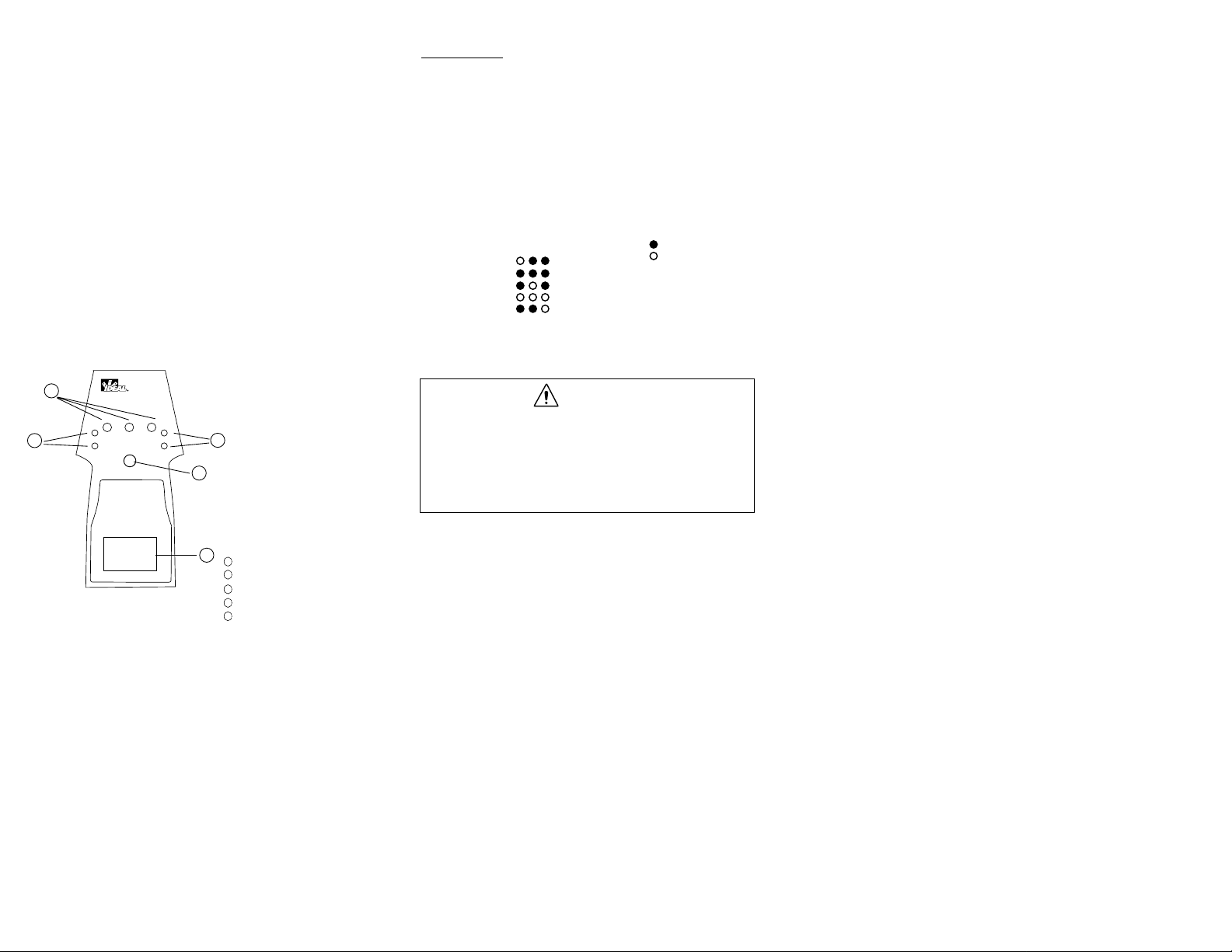
Front Panel Indicators
Test Procedures
Pass/Fail Indication
The ST-1D checks receptacles for proper wiring, and give a pass/fail indication of voltage drop and line voltage. These tests are performed immediately
upon insertion of the SureTest into the receptacle.
Wiring Verification
The ST-1D checks receptacle wiring for the following conditions:
Correct wiring, no ground, polarity reversed, no hot, or no neutral or hot and
ground reversed. These conditions are indicated on the wiring indicators.
Insert the ST-1D into the receptacle for indication of the wiring condition.
WARNING
An indication of “No Ground” on the wiring indicators indicates a
safety hazard is present. Defective grounds must be repaired prior to
the GFCI test.
The ST-1D will not indicate a reversal of the ground and neutral
connections, detect two hot connections, or indicate simultaneous
defects.
Wiring Indicators
Ground Impedance Indicators
Ground-to-Neutral Indicators
G.F.C.I. Test Button
LED Display
1
2
3
4
5
1
2
3
4
5
3
V
o
l
t
D
r
o
p
®
SureTest
Circuit Analyzer
Wiring Indicators
L
P
A
S
I
Y
D
A
E
D
C
V
N
A
61-152 ST-1D
1 = Line Voltage
2 = % Voltage Drop 15 AMP
3 = % Voltage Drop 20 AMP
4 = Highest Voltage Gnd./Neutral
5 = Load on line ± 10%
6 = Ground Impedance in Ohms
(Hold button insert Sure Test)
GFCI Test. Hold Button 3 Sec.
L
n
V
o
l
t
FG = False Ground
WIRING INDICATIONS
NORMAL
NO GROUND
POLARITY REVERSED
NO HOT
NO NEUTRAL or
HOT/GROUND REVERSED
OFF
ON
Page 3

65
Voltage Drop Testing
The ST-1D checks the voltage drop of a receptacle under a full 15 ampere
load without interruption to equipment on the circuit. The voltage drop
LEDs, located on the left side of the instrument, will indicate a pass/fail condition based on the maximum voltage drop for branch circuits recommended by the National Electrical Code for reasonable efficiency. (NEC article
210-19. FPN 4)
1. Insert the ST-1D into the receptacle
• Green confirms that a full 15 ampere load causes less than
a 5% voltage drop
• Amber indicates that the voltage drop in the circuit is greater than
5% under a full 15 ampere load
Line Voltage Testing
The St-1D checks line voltage of the receptacle to ensure that it is within
10% of the nominal line voltage. For the 120VAC version, #61-152, the
line voltage should be between 108 and 132 volts. For the 230VAC version,
#61-153, the line voltage should be between 207 and 253 volts.
1. Insert the ST-1D into the receptacle
• Green confirms that the line voltage is within 10%
• Red indicates that the line voltage is beyond the specified 10%
tolerance
NOTE: A failure of the line voltage test will force a failure of the voltage
drop test.
Electrical Measurements
In addition to pass fail/indication of key wiring and electrical test parameters, the ST-1D will measure key electrical values such as line voltage, voltage drop under 15 and 20 ampere loads, ground-to-neutral voltage, estimated load and ground impedance. These measurements are accessed
through a simple programming menu.
Unless a false ground condition exists, the ST-1D will show "L-n"- in the
LED display, located on the bottom of the instrument. This indicates that
the unit is calibrating itself prior to testing. After this calibration is performed, the ST-1D automatically enters into the programming menu. The
LED display cycles between the numerical sequence of the test, and the
measurement every four seconds. Press and hold the display advance button for 1 second to move through the menu to the next test.
1. Insert the ST-1D into the receptacle
2. The LED display will show "L-n"- to indicate self-calibration of the unit
3. The LED display will show “1=” to indicate that the first measurement is
being taken.
4. The first measurement is tested and displayed
5. The LED display alternates between the numerical sequence of the test
and the measurement every four seconds
6. Press and hold the display advance button for one second to move to
the next test
The fifth measurement, estimated load, is the final test in the menu.
Pressing and holding the display advance button will move back to line
voltage, the first test in the menu.
Line Voltage Measurement
The line voltage test is indicated on the LED display by “1=”. After four
seconds the display cycles to the actual line voltage measurement. The
LED display alternates between “1=” and the line voltage measurement
every four seconds.
Voltage Drop Measurement - 15 Amp Load
The voltage drop test at 15 Amps is indicated on the LED display by “2=”.
This measurement is tested under a full 15 ampere load without interruption
to equipment on the circuit. The National Electrical Code recommends 5%
as the maximum voltage drop for branch circuits for reasonable efficiency.
(NEC article 210-19. FPN 4)
Voltage Drop Measurement - 20 Amp Load
The voltage drop test at 20 Amps is indicated on the LED display by “3=”.
This measurement is calculated from a 15 ampere load.
Ground-to-Neutral Voltage Measurement
The ground-to-neutral voltage test is indicated on the LED display by “4=”.
Ground-to-neutral voltage results from current flowing in the neutral conductor from other equipment on the circuit. High ground-to-neutral voltage
indicates that the circuit may be loaded near its capacity or the neutral conductor may be shared or carrying harmonic distortion. A reading of less
than 2 volts usually indicates a usable outlet. An excessive ground-to-neutral voltage may result in inconsistent or intermittent equipment performance. This is a peak reading, which will be reset by pressing the display
advance button, and cycling through the menu until the LED display shows
“4=” again.
Page 4
87
This test can also be used to verify a dedicated circuit. A measurement
greater than 0.1 volts indicates that the receptacle under test is
not on a dedicated circuit. If the LED display is flashing, the unit
is unable to detect a ground. In the absence of a ground, the
ground-to-neutral voltage can not be misused. A reading of high
on the LED display indicates that the ground-to-neutral voltage is
greater than 2 volts.
Estimated Load Measurement
The estimated load test is indicated on the LED display by “5=”. A current
draw confirms that the receptacle under test is not on a dedicated circuit.
This is a peak reading, which will be reset by pressing the display advance
button, and cycling through the menu until the LED display shows “5=”
again.
This is the final measurement in the programming menu. Pressing and
holding the display advance button will move back to line voltage, the first
test in the menu.
Ground Impedance Measurement
WARNING
An indication of “No Ground” on the wiring indicators indicates a
safety hazard is present. Do not perform the ground impedance testing under these conditions.
The ground impedance measurement is a separate measurement and is outside the programming menu. To measure ground impedance, the SureTest
must be removed and re-inserted into the receptacle while pressing the display advance button.
The St-1D checks ground impedance by pulsing 15 amperes from hot-toground to ensure that the resistance is less than 1 Ohm. This test can not
be performed on a GFCI receptacle. The pulse will trip the GFCI.
1. Remove the ST-1D from the receptacle
2. Re-insert the St-1D into the receptacle while pressing the center button
3. The LED display will show "L-G” to indicate the ground impedance test
4. The LED display will show “6=” to indicate that the measurement is being
taken.
5. Ground impedance is measured and displayed
The ground impedance of an equipment chassis can be checked with #61175 ground continuity adapter.
1. Attach the #61-175 ground adapter to the ST-1D
2. Clip the alligator lead from the adapter to the equipment chassis
3. Insert the St-1D into the receptacle while pressing the center button The
LED display will show “L-G” to indicate the ground impedance test
4. The LED display will show “6=” to indicate that the measurement is being
taken.
5. Ground impedance is measured and displayed
G.F.C.I. Testing
The ST-1D applies 6mA to ground through a fixed resistor to trip the GFCI.
A functional GFCI will disconnect the power. The reset may be at the outlet
or at the panel.
WARNING
When testing 3-wire outlets, do not proceed with the GFCI test if the
Wiring Indicator lights indicate a “No Ground” condition exists.
Repair the ground circuit first.
1. Operate the test button on the GFCI installed in the circuit. The GFCI
should trip. If it does not, replace the GFCI. If it does trip, reset the
GFCI.
2. Insert the ST-1D into the receptacle.
3. Press the GFCI test button on the ST-1D for 6 seconds.
4. The actual current being applied to ground will be displayed.
5. (6mA is the nominal current sent through the fixed resistor. The actual
current will vary depending on the line voltage per UL1436.)
6. The tester will apply the current and count up to 6.5 seconds.
• If the GFCI is functioning properly, the circuit will disconnect, and the
LEDs on the ST-1D will go out. When the circuit is reset, and power
is returned, the LED display will show the actual time to trip.
• If the GFCI fails to trip, the LED display will show ìbAdî, which indi-
cates that the GFCI may be installed incorrectly, or the GFCI may be
defective.
Page 5
109
WARNING
In order to test GFCI’s in a 2-wire system (no ground wire), the #61-175
ground continuity adapter must be used. Connect the ground lead on
the adapter to a ground, such as a metal water or gas pipe.
Optional Accessories
#61-175 Ground Continuity Adapter
This adapter allows the operator to verify that a cabinet or equipment chassis has been properly connected to the power system ground. Plugging into
the #61-175 adapter will isolate the SureTest from the power source ground.
The Wiring Indicators of the unit will display a No Ground condition. If the
equipment is properly grounded, then touching the alligator clip from the
ground continuity adapter to the cabinet or equipment chassis should return
the circuit to a Normal condition.
WARNING
This is a static test and will not confirm the current carrying capacity
of the ground.
With the ST-1D, this adapter can be used to check the ground impedance of
a cabinet or equipment chasis. See the Ground Impedance Measurement
section for test instructions.
This adapter can also be used to test GFCI receptacles on 2-wire circuits.
Connect the ground lead on the adapter to a ground, such as a metal water
or gas pipe, prior to GFCI testing.
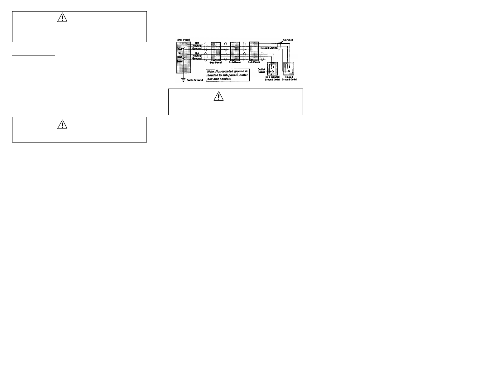
#61-176 Isolated Ground Adapter
This adapter allows the operator to verify that a receptacle is completely isolated from the other grounds between the receptacle and the entry panel.
WARNING
The receptacle should be tested for proper grounding prior to testing
for ground insulation.
Test the ground impedance of the receptacle and make a note of the results.
See the section on ground impedance testing for details. Remove the
SureTest from the receptacle and plug it into the #61-176 adapter. Clip the
ground wire to the metal outlet, center receptacle screw, or the metal outlet
box. Press the display advance button, and re-insert the ST-1D into the
receptacle. Make a note of the result.
If the two resistance readings are the same, then the receptacle is not isolated. If the receptacle is isolated, the reading with the #61-176 will be lower.
A reading of half when the adapter is used is common, because a parallel
ground path has been introduced by attaching the ground wire to the
grounding point of the receptacle.
#61-177 Extension Cord
The ST-1 is supplied with an extension cord to make testing easier on hardto-reach outlets. Replacement extension cords can be purchased from your
authorized IDEAL distributor.
Page 6
1211
#61-179 Carrying Case
The ST-1 is supplied with a lightweight carrying case to protect the units
and store the instruction sheet and accessories. Replacement cases can be
purchased from your authorized IDEAL distributor.
Troubleshooting
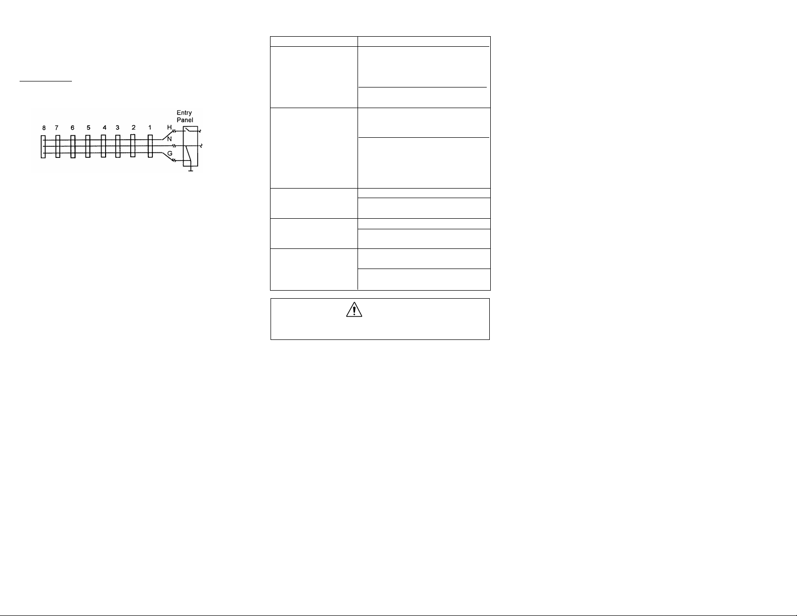
Locating Loose (High Resistance) Connections and Splices
Loose connections, splices and bad connections can be isolated by using
the SureTest to test receptacles in sequence along the branch circuit.
For example if the voltage drop at receptacle 5 is unacceptable, checking the
other receptacles in the branch can help isolate the problem. If receptacles
1 through 4 and 6 through 8 check out OK, than further investigation should
take place at the connection to receptacle 5. The additional resistance could
be due to a loose connection/splice. If receptacles 6 through 8 are also
unacceptable, chances are that the problem is in either the hot or neutral
conductor in the wall between receptacles 4 and 5.
If all of the branch receptacles have unacceptable voltage drops, the problem
is most likely in the circuit between the panel and the first receptacle or at
the panel. If all branches are in high resistance, the problem may be in the
circuit from the meter, or from the transformer to the service entrance.
Using the SureTest will help identify problem areas for further investigation
of the receptacles and/or branch circuit.
Troubleshooting Tips
Problem Possible Causes/Solutions
High/Low Line Voltage • Too much load on branch ñ also causing
excessive voltage drop
• Poor connection at receptacle
• Supply voltage too high/low
• Clean and tighten receptacle connections
• Consult power company
High Voltage Drop • Too much load on branch
(5% recommended by NEC) • Too many outlets on branch
• Diameter of wire too small
• Check and tighten connection at
receptacle
• Clean any corroded wires
• Replace outlet, switch
• Replace circuit breaker
High Ground-to-Neutral • Current flowing in the neutral conductor
Voltage (Greater than • Locate/repair source
2 Volts) • Install surge suppression
High Ground Impedance • Loose ground connection
(Greater than 1 Ohm) • Check and tighten ground connections
• Clean any corroded wires
Failure of GFCI Test • GFCI may be installed incorrectly
(GFCI will not trip) • GFCI may be defective
• Check for proper connections
• Replace outlet
WARNING
Maintenance on electrical wiring should only be performed by qualitied personnel.
Page 7
1413
Other SureT
est Models from IDEAL
SureTest Circuit Analyzers
SureTest Circuit/Harmonics Analyzers
SureTest®Selection Guide
Identifies and Locates
Loose Wire Connections ••••
Bad Splices/Receptacles ••••
High Resistance Grounds ••••
False (Bootleg) Grounds •••
Shared Neutrals ••
Indicates
Proper Wiring in 3-Wire Receptacles ••••
Min/Max Line Voltage •••
Pass/Fail Voltage Drop •••
Pass/Fail Ground Impedance •
Pass/Fail Neutral-to-Ground Voltage •
Verifies
Dedicated Circuit Presence ••
Isolated Ground Presence (with #61-176 Adapter) •••
Proper GFCI Operation ••••
Measures
Line Voltage •••
Ground Impedance (Ohms) ••
% Voltage Drop under 15 ampere load •••
% Voltage Drop under 20 ampere load ••
GFCI Trip Time •••
Neutral-to-Ground Voltage ••
Estimated Load on Circuit (Amps) ••
Additional Features
220 VAC Operation •
61-150
ST-1
61-151
ST-1P+
61-152
ST-1D
61-153
ST-1D
SureTest®Selection Guide
61-156
ST-1THD
61-157
ST-1THDC
61-158
Identifies and Locates
Loose Wire Connections •••
Bad Splices/Receptacles •• •
High Resistance Grounds •••
False (Bootleg) Grounds •••
Shared Neutrals •••
Verifies
Dedicated Circuit Presence •••
Isolated Ground Presence (with #61-176 Adapter) ••
Proper GFCI Operation •••
Measures
Line Voltage •••
Ground Impedance (Ohms) •••
% Voltage Drop under 15 ampere load •••
% Voltage Drop under 20 ampere load •••
GFCI Trip Time •••
Neutral-to-Ground Voltage •••
Estimated Load on Circuit (Amps) •••
True RMS Measurements (Voltage) •• •
True RMS Measurements (Current)
(with #61-181 Adapter) • •
Line Frequency •••
Power Consumption (Watts) •••
Distortion to 31st Harmonic •••
Additional Features
220 VAC Operation
For use with #61-181 500AAC Adaptor ••
Included with #61-181 500AAC Adaptor •
Event recording •• •
ST-1THDC
Page 8

Warranty limited solely to repair or replacement; no warranty of merchantability, fitness for a particular purpose or consequential damages.
IDEAL INDUSTRIES, INC.
Sycamore, IL 60178, U.S.A.
800-435-0705 Customer Assistance
www.idealindustries.com
ND 2291-2 Made in U.S.A.
 Loading...