

Page 1

Minimiser FF 30-80
Installation & Servicing
Wall Mounted, Fanned, Super Efficient Gas Boilers
Natural Gas Models Only
Minimiser G.C. Appliance No.
FF 30 .........................41 387 16
FF 40 .........................41 387 17
FF 50 .........................41 387 18
CAUTION. To avoid the possibility of injury during the installation, servicing or cleaning of this
appliance care should be taken when handling edges of sheet steel components.
Minimiser G.C. Appliance No.
FF 60 .........................41 387 19
FF 70 .........................41 387 20
FF 80 .........................41 387 21
NOTE TO THE INSTALLER: LEAVE THESE INSTRUCTIONS ADJACENT TO THE GAS METER
Page 2

GENERAL
CONTENTS
Air Supply ...................................................................... 6
INTRODUCTION
Minimiser FF 30-80 are fully automatically controlled, wall
mounted, low water content, balanced flue, fanned super
efficient condensing gas boilers. They are spot-rated to
provide central heating outputs of 8.8 kW (30,000 Btu/h) to
23.4 kW (80,000 Btu/h).
Boiler Clearances .......................................................... 4
Boiler Exploded Diagram ........................................... 11
Electrical Connections ............................................... 21
Electrical Supply ........................................................... 6
Electrical Systems Diagrams ..................................... 23
Extension Ducts - Fitting ............................................ 20
Fault Finding ............................................................... 42
Flow Wiring Diagram .................................................. 22
Flue Fitting
Rear outlet .............................................................. 14
Side outlet .............................................................. 17
Flue Installation ............................................................. 5
Gas Safety (Installation & Use)
Regulations, 1994 ......................................................... 2
Gas Supply .................................................................... 5
Health & Safety Document No 635 .............................. 3
Due to the high efficiency of the boiler a plume of water vapour
will form at the flue terminal during operation.
The boiler casing is of white painted mild steel with a dropdown control pod door. The controls pod, also of white painted
mild steel, has fixed sides and a removable bottom panel.
The boiler thermostat is located behind the controls pod door.
The heat exchanger is of aluminium.
Note. These boilers cannot be used on systems which include
gravity circulation.
The boilers are suitable for connection to fully pumped, open
vented or sealed water systems. Adequate arrangements for
completely draining the system by provision of drain cocks
MUST be provided in the installation pipework.
OPTIONAL EXTRA KITS
Programmer Kit Fits neatly within the casing, is available.
Separate fitting instructions are included
with this kit.
Roof Flue Kit For vertical flue connection.
Powered Vertical For extended vertical flue connection.
Flue (K Pack)
Extension Ducts Up to 3.1m (122") are available.
Wall Mounting Enables the boiler to be mounted with the
Stand-off Kit Front flush with 300mm deep kitchen units.
Installation ................................................................... 12
Mandatory Requirements ............................................. 4
Pump ............................................................................ 7
Servicing ...................................................................... 29
Short List of Parts ....................................................... 47
System Diagrams .......................................................... 7
Terminal Guards............................................................ 5
Water Connections ....................................................... 4
Water and Systems ....................................................... 6
Wiring Diagrams.......................................................... 22
GAS SAFETY (INSTALLATION AND USE)
REGULATIONS, 1994
It is law that all gas appliances are installed and serviced by a
CORGI registered installer (identified by
with the above regulations. Failure to install appliances
correctly could lead to prosecution. It is in your own interest,
and that of safety, to ensure the law is complied with.
The installation of the boiler MUST also be in accordance with
the latest I.E.E Wiring Regulations, local building regulations,
bye-laws of the local water authority, the building regulations
and the Building Standards (Scotland) and any relevant
requirements of the local authority.
Detailed recommendations are contained in the following British
Standard Codes of Practice:
BS. 6891 Low pressure installation pipes.
BS. 6798 Installation of gas fired hot water boilers of rated
input not exceeding 60 kW.
BS. 5449 Forced circulation hot water systems.
BS. 5546 Installation of gas hot water supplies for
domestic purposes (2nd Family Gases)
BS. 5440:1 Flues (for gas appliances of rated input not
exceeding 60 kW)
BS. 5440:2 Ventilation (for gas appliances of rated input not
exceeding 60 kW)
) in accordance
2
Minimiser - Installation
Page 3

PERFORMANCE DATA
Table 1 - General Data
Boiler Size FF 30 FF 40 FF 50 FF 60 FF 70 FF 80
Gas supply connection (in. BSP) Rc
Flow connection 22mm copper (via adaptors 28mm copper
(FEMALE) supplied) (MALE)
Return connection 22mm copper (via adaptors 28mm copper
(FEMALE) supplied) (MALE)
Maximum static water head m (ft.) 30.5 (100)
Minimum static water head m (ft.) 0.45 (1.5)
Electrical supply 230 V ~ 50 Hz
Boiler power consumption 50W
Fuse rating External: 3A Internal: F2A to BS 4265
Water content litre (gal.) 1.65 (0.36) 1.95 (0.43)
Dry Weight kg (lb.) 26.0 (57.3) 27.0 (59.5)
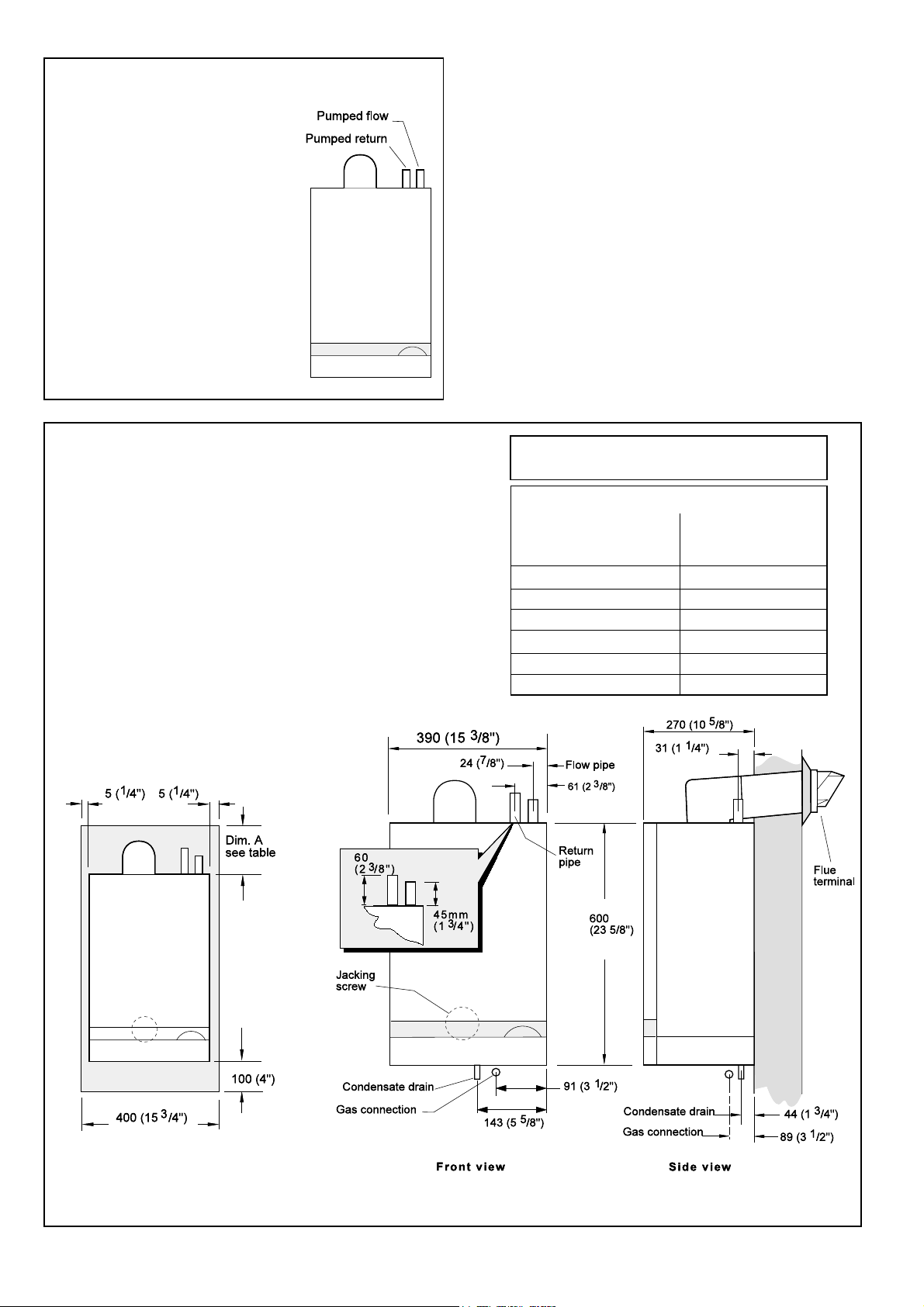
Boiler size Height mm (in.) 600 (23.6)
Width mm (in.) 390 (15.0)
Depth mm (in.) 270 (10.6)
Flue duct diameter mm (in.) 100 (4.0)
1/2 (1/2" BSP Female)
GENERAL
Table 2 - Performance Data
Boiler Size FF 30 FF 40 FF 50 FF 60 FF 70 FF 80
Boiler input Nett kW 9.2 12.3 15.3 18.4 21.5 24.6
CV Btu/h 31,400 42,000 52,200 62,800 73,400 84,000
Boiler input Gross kW 10.2 13.6 17.0 20.4 23.9 27.3
CV Btu/h 34,900 46,500 58,100 69,800 81,400 93,000
Gas consumption l/s (cu.ft/h) 0.26 (33.6) 0.35 (44.9) 0.44 (56.1) 0.53 (67.3) 0.62 (78.6) 0.70 (89.8)
Boiler output 70° C Mean water kW 8.8 11.7 14.7 17.6 20.5 23.4
temperature Btu/h 30,000 40,000 50,000 60,000 70,000 80,000
40° C Mean water kW 9.4 12.5 15.7 18.8 21.9 25.1
temperature Btu/h 32,100 42,800 53,500 64,200 74,900 85,600
Burner Setting mbar 10.7 10.0 8.6 10.5 5.3 8.8
pressure (HOT) in.w.g. 4.3 4.0 3.5 4.2 2.1 3.5
HEALTH & SAFETY DOCUMENT NO 635
Notes.
The Electricity at Work Regulations, 1989.
The manufacturer’s notes must NOT be taken, in any way, as
overriding statutory obligations.
To obtain the gas consumption:-
IMPORTANT. These appliances are CE certificated for safety
and performance. It is, therefore, important that no external
a. For l/s divide the gross heat input (kW) by
C.V. of the gas (MJ/m3)
b. For ft3/h divide the gross heat input (Btu/h)
by C.V. of the gas (Btu/ft3)
control devices, e.g. flue dampers, economisers etc., are
directly connected to these appliances unless covered by these
Installation and Servicing Instructions or as otherwise
recommended by Caradon Ideal Limited in writing. If in doubt
please enquire.
Any direct connection of a control device not approved by
Caradon Ideal Ltd. could invalidate the certification and the
normal appliance warranty. It could also infringe the Gas Safety
Regulations and the above regulations.
Minimiser - Installation
3
Page 4
GENERAL
1
BOILER WATER CONNECTIONS
The boiler flow and return pipes are
supplied fitted to the boiler ready for top
connection but can be removed and
adapted for bottom connection, if required,
either before or after the boiler is hung on
the wall - refer to Frame 43.
Notes.
a. For the 70 and 80 boilers, 28mm (1")
flow and return pipes should be used to
and from the boiler.
For the 30 to 60 boilers, 22mm (3/4")
pipes may be used to connect the
boiler, using the 28mm x 22mm
adaptors supplied in the hardware
pack.
b. This appliance is NOT suitable for use
with a direct hot water cylinder.
2
BOILER CLEARANCES all dimensions in mm (in.)
The following minimum clearances must be maintained for operation
and servicing.
Additional space will be required for installation, depending upon site
conditions.
Side and Rear Flue
a Provided that the flue hole is cut accurately, e.g. with a core drill,
the flue can be installed from inside the building where wall
thicknesses do not exceed 600mm (24"). Where the space into
which the boiler is going to be installed is less than the length of
flue required the flue must be fitted from the outside.
Installation from inside ONLY
b If a core boring tool is to be used inside
the building the space in which the boiler
is to be installed must be at least wide
enough to accommodate the tool.
LOCATION OF BOILER
The boiler must be installed on a flat and vertical wall, capable
of adequately supporting the weight of the boiler and any
ancillary equipment.
The boiler may be fitted on a combustible wall and insulation
between the wall and the boiler is not necessary, unless required
by the local authority.
The boiler must not be fitted outside.
Timber Framed Buildings
If the boiler is to be fitted in a timber framed building it should be
fitted in accordance with the British Gas publication 'Guide for
Gas Installations in Timber Frame Housing', reference DM2.
REAR FLUE ONLY
MIN. Top clearance required = 145 mm (5 3/4")
SIDE FLUE ONLY
Horizontal length of flue Top clearance
from centre line of boiler required (MIN.)
to outside wall Dimn. A
0.5 m 160 mm (6
1.0 m 180 mm (7 7/8")
1.5 m 205 mm (8 1/16")
2.0 m 225 mm (8
2.5 m 250 mm (9 3/4")
3.0 m 270 mm (10 5/8")
5/16")
7/8")
Front clearance: 450mm (17 3/4") from the
front of the boiler casing. The minimum
front clearance when built in to a cupboard
is 5mm (1/4")
4
Minimiser - Installation
Page 5

GENERAL
Bathroom Installations
The boiler may be installed in any room or internal space,
although particular attention is drawn to the requirements of the
current I.E.E. (BS7671) Wiring Regulations and, in Scotland, the
electrical provisions of the building regulations applicable in
Scotland with respect to the installation of the boiler in a room or
internal space containing a bath or shower.
Where a room sealed appliance is installed in a room containing
a bath or shower then the appliance and any electrical switch or
appliance control utilising mains electricity should be so situated
that it cannot be touched by a person using the bath or shower.
Where installation will be in an unusual location, special
procedures may be necessary and BS 6798 gives detailed
guidance on this aspect.
Compartment Installations
A compartment used to enclose the boiler should be designed
and constructed specially for this purpose.
An existing cupboard or compartment may be used, provided
that it is modified for the purpose.
In both cases details of essential features of cupboard /
compartment design, including airing cupboard installation, are
to conform to the following:
z BS. 6798.
z The position selected for installation MUST allow adequate
space for servicing in front of the boiler. Ventilation of the
compartment is not necessary.
z For the minimum clearances required for safety and
subsequent service, see the wall mounting template and
Frame 2. In addition, sufficient space may be required to
allow lifting access to the wall mounting plate.
GAS SUPPLY
The local gas supplier should be consulted, at the installation
planning stage, in order to establish the availability of an
adequate supply of gas. An existing service pipe must NOT be
used without prior consultation with the local gas supplier.
A gas meter can only be connected by the local gas supplier or
by a registered CORGI engineer.
An existing meter should be checked, preferably by the gas
supplier, to ensure that the meter is adequate to deal with the
rate of gas supply required. A minimum working gas pressure of
20 mbar MUST be available at the boiler inlet.
Installation pipes MUST be fitted in accordance with BS. 6891.
Pipework from the meter to the boiler MUST be of an adequate
size, i.e. not less than 15mm O.D. Note. For pipe runs greater
than 3m (10'), 22mm O.D. pipe is recommended.
Do not use pipes of smaller size than the boiler inlet gas
connection.
The complete installation MUST be tested for gas soundness
and purged as described in the above code.
FLUE INSTALLATION
Pluming will occur at the termination so, where possible,
terminal positions which could cause this nuisance should be
avoided.
The flue must be installed in accordance with the
recommendations of BS. 5440: Part 1.
The following notes are intended for general guidance.
1. The boiler MUST be installed so that the terminal is exposed
to external air.
2. It is important that the position of the terminal allows the free
passage of air across it at all times.
3. Minimum acceptable spacing from the terminal to
obstructions and ventilation openings are specified in
Table 3.
Note positions 2-6 : Due to the terminal design, installation is
possible with clearances less than those specified in BS 5440,
Part 1.
Table 3 - Balanced flue terminal position
Terminal Position
1. Directly below or alongside an
openable window, air vent or other 300 mm (12")
ventilation opening
2. Below guttering, drain pipes or soil
pipes 25 mm ( 1")
3. Below eaves 25 mm ( 1")
4. Below balconies or a car port roof 25 mm ( 1")
5. From vertical drain pipes or soil pipes 25 mm ( 1")
6. From internal or external corners 25 mm ( 1")
7. Above adjacent ground, roof or
balcony level 300 mm (12")
8. From a surface facing the terminal 600 mm (24")
9. From a terminal facing a terminal 1200 mm (48")
10. From an opening in a car port
(e.g. door or window) into dwelling 1200 mm (48")
11. Vertically from a terminal on the
same wall 1500 mm (60")
12. Horizontally from a terminal on the wall 300 mm (12")
4. Where the lowest part of the terminal is fitted less than 2m
(6'6") above a balcony, above ground or above a flat roof to
which people have access, then the terminal MUST be
protected by a purpose designed guard. The minimum
spacing in Table 3, Nos. 2, 3, 4, 5 and 6 would be 75mm, in
order to allow a terminal guard to be fitted.
Terminals guards are available from boiler suppliers - ask for
Tower Flue Guard, Model K1 . In case of difficulty seek
advice from:
Tower Flue Components Ltd.,
Vale Rise, Tonbridge, Kent TN9 1TB
Telephone No. 01732 351 555.
Ensure that the guard is fitted centrally.
5. Where the terminal is fitted within 850mm (34") of a plastic or
painted gutter or 450mm (18") of painted eaves then an
aluminium shield at least 750mm (30") long should be fitted
to the underside of the gutter or painted surface.
6. The air inlet/products outlet duct and the terminal of the
boiler MUST NOT be closer than 25mm (1") to combustible
material. Detailed recommendations on the protection of
combustible material are given in BS. 5440: 1990.
7. Where it is essential that the terminal wall plate is fitted, i.e.
wall thicknesses over 610mm (24") or with an inaccurately
cut hole, the minimum spacing in Table 3, Nos. 2, 3, 4, 5 and
6 would be 60mm (2.4") in order to allow the terminal wall
plate to be fitted.
Minimum Spacing
Minimiser - Installation
5
Page 6

GENERAL
IMPORTANT. It is absolutely ESSENTIAL to ensure, in
practice, that products of combustion discharging from the
terminal cannot re-enter the building or any other adjacent
building through ventilators, windows, doors, other sources of
natural air infiltration, or forced ventilation / air conditioning.
If this should occur the appliance MUST be turned OFF, labelled
as 'unsafe' and corrective action taken.
TERMINAL
The terminal assembly can be adapted to accommodate various
wall thicknesses. Refer to Frame 11 - Unpacking.
AIR SUPPLY
It is NOT necessary to have a purpose-provided air vent in the
room or internal space in which the boiler is installed. Neither is
it necessary to ventilate a cupboard or compartment in which
the boiler is installed, due to the low surface temperatures of
the boiler casing during operation; therefore the requirements
of BS 6798, Clause 12, and BS 5440:2 may be disregarded.
WATER CIRCULATION SYSTEM
The boiler must NOT be used for direct hot water supply. For the
types of system and correct piping procedure see Frames 1
and 3 to 8.
The central heating system should be in accordance with
BS. 6798 and, in addition, for smallbore and microbore systems,
BS. 5449.
WATER TREATMENT - see Frame 9
The hot water storage cylinder MUST be of the indirect type
and should preferably be manufactured of copper.
Single feed, indirect cylinders are not recommended and
MUST NOT be used on sealed systems.
Table 4 - Water flow rate and pressure loss
Boiler size FF30 FF40 FF50 FF60 FF70 FF80
Boiler kW 8.8 11.7 14.7 17.6 20.5 23.4
Output Btu/h
Water Flow l/sec 0.19 0.25 0.32 0.38 0.44 0.51
Rate gpm 2.5 3.3 4.2 5.0 5.8 6.7
Pressure kPa 4.2 6.7 10.0 13.7 11.2 13.7
Loss m 0.4 0.7 1.0 1.4 1.2 1.4
30,000 40,000 50,000 60,000 70,000 80,000
ft 1.4 2.3 3.3 4.6 3.8 4.6
THERMOSTATIC RADIATOR VALVES (TRV)
Caradon Ideal Ltd. recommend that heating systems utilising
full thermostatic radiator valve control of temperature in
individual rooms should also be fitted with a room thermostat
controlling the temperature in a space served by radiators not
fitted with such a valve as stated in BS. 5449.
When thermostatic radiator valves are used, the space heating
temperature control over a living area having a heating
requirement of at least 60% of the boiler heat output should be
achieved using a room thermostat whilst other rooms are
individually controlled by thermostatic radiator valves. A higher
proportion of TRVs may be used, provided that a bypass
between the boiler flow and return is fitted, to ensure adequate
flow when all TRVs are closed - however this is NOT
recommended as a large proportion of TRV's can restrict water
circulation and inhibit the condensing mode of condensing
boilers, reducing fuel economy.
For further information refer to the 'Good Practice Guide 143',
publication of the Energy Efficiency Office, available from the
Building Research Establishment, Garston, Watford WD2 7JR.
Tel: 01923 664 258
The appliances are NOT suitable for gravity central heating nor
are they suitable for the provision of gravity domestic hot water.
The hot water cylinder and ancillary pipework, not forming part
of the useful heating surface, should be lagged to prevent heat
loss and any possible freezing - particularly where pipes run
through roof spaces and ventilated underfloor spaces.
The boiler must be vented.
Draining taps MUST be located in accessible positions, which
permit the draining of the whole system - including the boiler
and hot water storage vessel. They should be at least
nominal size and be in accordance with BS. 2879.
The boiler is fitted with a special drain plug which is provided to
drain the BOILER ONLY in the event of the system drain plug
being unable to do so.
The hydraulic resistance of the boilers, at MAXIMUM OUTPUT,
with an 11
Table 4.
0
C (20 0F) temperature differential, are shown in
1/2" BSP
ELECTRICAL SUPPLY
Wiring external to the appliance MUST be in accordance with the
current I.E.E. (BS7671) Wiring Regulations and any local
regulations which apply.
The point of connection to the mains should be readily
accessible and adjacent to the boiler, except for bathroom
installations where the point of connection to the mains MUST be
situated outside of the bathroom.
Note. Where a room sealed appliance is installed in a room
containing a bath or shower then the appliance and any
electrical switch or appliance control utilising mains electricity
should be so situated that it cannot be touched by a person
using the bath or shower. See Frame 34 for details.
6
Minimiser - Installation
Page 7
GENERAL
3
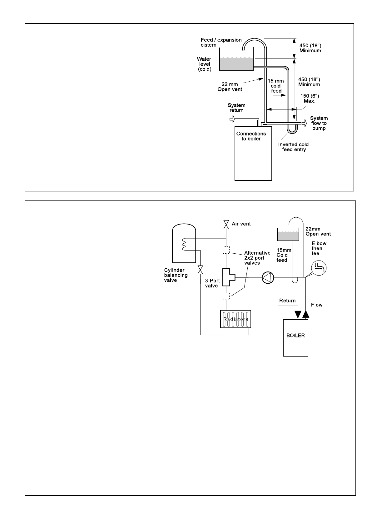
OPEN VENT SYSTEM REQUIREMENTS
The system should be vented directly off the boiler flow pipe, as
close to the boiler as possible. The cold feed entry should be
inverted and MUST be positioned between the pump and the vent,
and not more than 150mm (6") away from the vent connection.
Note. Combined feed and vent pipes may also be fitted.
There should be a minimum height, 450mm (18"), of open vent
above the cistern water level. If this is not possible refer to
Frame 5. The vertical distance between the highest point of the
system and the feed/expansion cistern water level MUST not be
less than 450 mm (18"). The pump must be fitted on the flow side
of the boiler.
A suitable pump is a domestic circulator capable of providing a maximum 11°C
(20°F) temperature differential across the boiler with the whole of the heating
circuit open (e.g. Grundfos UPS 15/50, 15/60 or equivalent). With the minimum
flow circuit allowed by the controls the differential must not exceed 15 °C.
The vertical distance between the pump and feed/expansion cistern MUST
comply with the pump manufacturer's minimum requirements, to avoid
cavitation. Should these conditions not apply either lower the pump position or
raise the cistern above the minimum requirement specified by Caradon Ideal
Ltd. The isolation valves should be fitted as close to the pump as possible.
4
SCHEMATIC PIPEWORK AND SYSTEM BALANCING
all dimensions in mm (in.)
Return & flow connections
FF 30 - 60 = 22 mm
FF 70 - 80 = 28 mm
The boiler does not normally need a
bypass but at least some radiators on the
heating circuit, of load at least 60% of the
boiler output, must be provided with twin
lockshield valves so that this minimum
heating load is always available (see
footnote re. thermostatic radiator valves).
Balancing
1. Set the programmer to ON for both
CH and HW. Turn the cylinder
thermostat down. Close the manual or
thermostatic valves on all radiators,
leaving the twin lockshield valves (on
the radiators referred to above) in the
open position. Turn up the room
thermostat and adjust these lockshield
valves to give boiler flow and return
temperatures not more than 15°C
apart. These valves should now be left
as set.
2. Open all manual or thermostatic radiator
valves and adjust the lockshield valves on
remaining radiators to give around 11°C
temperature drop at each radiator.
3. Turn up the cylinder thermostat and adjust the
cylinder balancing valve so that the cylinder
achieves a maximum flow consistent with
adequate flow to the radiators. Check that with
only the domestic hot water loop in circuit a
differential temperature of 15 °C across the
boiler is not exceeded.
4. Adjust room and cylinder thermostats and
programmer to NORMAL settings.
Thermostatic Radiator Valves
Caradon Ideal Ltd. support the recommendations made in BS. 5449,
and by leading manufacturers of domestic heating controls, that
heating systems utilising the thermostatic radiator valve control of
temperature in individual rooms shall also be fitted with a room
thermostat, controlling the temperature in a space served by radiators
not fitted with such a valve.
Such an arrangement will provide for potentially more efficient control
of the environment and will also avoid the continuous running of the
circulation pump during programmed heating ON periods - thus
saving electrical energy.
It is, therefore, strongly recommended that, when thermostatic
radiator valves are used, space heating temperature control over a
living/dining area or a hallway having a heating requirement of at
least 60% of the boiler heat output, is achieved using a room
thermostat whilst other rooms are individually controlled by
thermostatic radiator valves.
Minimiser - Installation
7
Page 8

GENERAL
5
LOW HEAD AND LARGE SYSTEMS WITH EXTENSIVE PIPE RUNS - OPEN VENT
This arrangement is useful for large systems where
radiators at the extremities are difficult to vent. This can
lead to pumping over with conventional feed and vent
arrangements.
The following conditions MUST be observed:
1. The top of the automatic air vent must be below the
cold water level.
2. The static water level (cold) must be at least 200mm
above the top of the horizontal flow pipe, fitted as
shown. The vent connection MUST NOT be made
immediately off the top of the boiler as venting is
made less efficient.
3. The maximum practical length of 22mm cold feed pipe
should be used in order to reduce the effective volume
of hot system water expanding into the feed/
expansion cistern to a minimum.
Note. The pump manufacturers' minimum requirements must be complied with.
All dimensions in mm (in.).
NB. Imperial dimensions are approximate
6
SEALED SYSTEM REQUIREMENTS
Note.The method of filling, refilling, topping up or
flushing sealed primary hot water circuit from the
mains via a temporary hose connection is only
allowed if acceptable to the local water authority.
1. General
a. The
installation
must comply
with the
requirements
of BS. 6798
and BS.
5449.
b. The
installation
should be
designed to work with
flow temperatures of up to 82° C.
c. All components of the system, including the heat
exchanger of the indirect cylinder, must be
suitable for a working pressure of 3 bar (45lb/in
and temperature of 110°C. Care should be taken
in making all connections so that the risk of
leakage is minimised.
2. Safety Valve
A spring loaded safety valve complying with the
relevant requirements of BS. 6759 must be fitted in
the flow pipe as close to the boiler as possible and
with no intervening valve or restriction. The valve
should have the following features:
a. A non-adjustable preset lift pressure not
exceeding 3bar (45lb/in
2
).
2
)
b. A manual testing device.
c. Provision for connection of a discharge pipe.
The valve or discharge pipe should be positioned so
that the discharge of water or steam cannot create a
hazard to the occupants of the premises or cause
damage to electrical components and wiring.
3. Pressure Gauge
A pressure gauge covering at least the range 0-4 bar
(0-60 lb/in
be easily seen from the filling point and should preferably be
connected at the same point as the expansion vessel.
2
) must be fitted to the system. The gauge should
8
Minimiser - Installation
Page 9

7
SEALED SYSTEM REQUIREMENTS - continued
4. Expansion Vessel
GENERAL
a. A diaphragm type expansion vessel must be
connected to a point close to the inlet side of the
pump, the connecting pipe being not less than 15 mm
1/2" nominal) size and not incorporating valves of any
(
sort.
b. The vessel capacity must be adequate to accept the
expansion of the system water when heated to 110° C
(230° F).
c. The charge pressure must not be less than the static
water head above the vessel. The pressure attained in
the system when heated to 110° C (230° F) should be
at least 0.35 bar (5 Ib/in
2
) less than the lift pressure of
the safety valve.
For guidance on vessel sizing refer to the table in
Frame 8.
For further details refer to BS. 5449, BS. 7074:1 and
the British Gas Corporation publication 'Material and
Installation Specifications for Domestic Central
Heating and Hot Water'.
5. Cylinder
The cylinder must be either of the indirect coil type or a
direct cylinder fitted with an immersion calorifier which is
suitable for operating on a gauge pressure of 0.35 bar
2
(5 Ib/in
) in excess of the safety valve setting. Single feed
indirect cylinders are not suitable for sealed systems.
6. Make-up Water
Provision must be made for replacing water loss from the
system, either:
a. From a manually filled make-up vessel with a readily
visible water level. The vessel should be mounted at
least 150 mm (6") above the highest point of the
system, and be connected through a non-return valve
to the system, fitted at least 300 mm (12") below the
make-up vessel on the return side of the domestic hot
water cylinder or radiators.
or
b. Where access to a make-up vessel would be difficult
by pre-pressurisation of the system. Refer to 'Filling',
below.
7. Mains Connection
There must be no direct connection to the mains water
supply or to the water storage tank supplying domestic
water, even through a non-return valve, without the
approval of the local water authority.
8. Filling
The system may be filled by one of the following methods:
a. Through a cistern, used for no other purposes, via a
ball valve permanently connected directly to a service
pipe and/or a cold water distributing pipe.
The static head available from the cistern should be
adequate to provide the desired initial system design
pressure. The cold feed pipe from the cistern should
include a non-return valve and a stop valve with an
automatic air vent connected between them, the stop
valve being located between the system and the
automatic air vent. The stop valve may remain open
during normal operation of the system if automatic
water make-up is required.
b. Through a self-contained unit comprising a cistern,
pressure booster pump (if required) and, if necessary,
an automatic pressure reducing valve and flow
restrictor. The cistern should be supplied through a
temporary connection from a service pipe or cold water
distributing pipe.
This unit may remain permanently connected to the
heating system to provide limited automatic water
make-up. Where the temporary connection is supplied
from a service pipe or distributing pipe which also
supplies other draw-off points at a lower level then a
double check valve shall be installed upstream of the
draw-off point.
c. Through a temporary hose connection from a draw-off
tap supplied from a service pipe under mains
pressure. Where the mains pressure is excessive a
pressure reducing valve shall be used to facilitate
filling.
The following fittings shall form a permanent part of
the system and shall be fitted in the order stated:
A stop valve complying with the requirements of
BS. 1010, Part 2 (the hose from the draw-off tap shall
be connected to this fitting).
A test cock.
A double check valve of an approved type.
• Thoroughly flush out the whole of the system with cold
water, without the pump in position.
• With the pump fitted, fill and vent the system until the
pressure gauge registers 1.5 bar (21.5lb/in
2
). Examine
for leaks.
• Check the operation of the safety valve by manually
raising the water pressure until the valve lifts. This
should occur within ± 0.3 bar (± 4.3lb/in
2.
) of the pre-
set lift pressure.
• Release water from the system until the initial system
design pressure is reached.
• Light the boiler and heat the system to the maximum
working temperature. Examine for leaks.
• Turn off the boiler and drain the system while still hot.
• Refill and vent the system.
• Adjust the initial pressure to the required value.
Sizing procedure for expansion vessels: The volume of the expansion vessel (litres) fitted to a sealed system shall not be
less than that given by the table on the following page, multiplied by a factor of 0.8 (for flow temperatures of less than 83° C).
Minimiser - Installation
9
Page 10

GENERAL
8
SEALED SYSTEM REQUIREMENTS - continued
Safety valve setting 3.0 bar 2.5 bar 2.0 bar
Vessel charge and initial 0.5 1.0 1.5 0.5 1.0 1.5 0.5 1.0
system pressure bar bar bar bar bar bar bar bar
Total water content of system Expansion vessel volume litres
25 litres 2.1 2.7 3.9 2.3 3.3 5.9 2.8 5.0
50 4.2 5.4 7.8 4.7 6.7 11.8 5.6 10.0
75 6.3 8.2 11.7 7.0 10.0 17.7 8.4 15.0
100 8.3 10.9 15.6 9.4 13.4 23.7 11.3 20.0
125 10.4 13.6 19.5 11.7 16.7 29.6 14.1 25.0
150 12.5 16.3 23.4 14.1 20.1 35.5 16.9 30.0
175 14.6 19.1 27.3 16.4 23.4 41.4 19.7 35.0
200 16.7 21.8 31.2 18.8 26.8 47.4 22.6 40.0
225 18.7 24.5 35.1 21.1 30.1 53.3 25.4 45.0
250 20.8 27.2 39.0 23.5 33.5 59.2 28.2 50.0
275 22.9 30.0 42.9 25.8 36.8 65.1 31.0 55.0
300 25.0 32.7 46.8 28.2 40.2 71.1 33.9 60.0
Multiplying factors for
other system volumes 0.0833 0.109 0.156 0.094 0.134 0.237 0.113 0.20
9
WATER TREATMENT
The Minimiser boiler has an ALUMINIUM alloy heat exchanger
If water treatment is used Caradon Ideal recommend only the use of FERNOX-COPAL or SENTINEL X100 water treatment
products, which must be used in accordance with the manufacturers' instructions. For further information contact:-
Fernox Manufacturing Co. Ltd.
Britannica Works
Clavering
Essex
CB11 4QZ
01799 550811
Sentinel Division
Grace Dearborn Ltd.
Widnes
Cheshire
WA8 8UD
0151 424 5351
IMPORTANT.
The application of any other treatment to this product will render the guarantee of Caradon Ideal invalid.
Notes.
1. It is most important that the correct concentration of the water treatment product is maintained in accordance with the
manufacturers' instructions.
2. If the boiler is installed in an existing system any unsuitable additives MUST be removed by thorough cleansing.
BS. 7593:1992 details the steps necessary to clean a domestic central heating system.
3. In hard water areas, treatment to prevent lime scale may be necessary - however, the use of artificially softened water is NOT
permitted.
4. Under no circumstances should the boiler be fired before the system has been thoroughly flushed.
10
Minimiser - Installation
Page 11

CONDENSATE DRAIN - Refer to Frame 44
A condensate drain is provided on the boiler. This drain must be
connected to a drainage point on site. All pipework and fittings
in the condensate drainage system MUST be made of plastic -
no other materials may be used.
10
BOILER ASSEMBLY - Exploded view
16
23
INSTALLATION
Important.
Any external runs must be insulated
The drain outlet on the boiler is standard
(22 mm) overflow pipe.
5
4
21
7
3/4"
2
22
20
6
11
1
9
15
14
8
3
19
INSTALLATION
18
17
12
LEGEND
1. Fan assembly
2. Flue outlet elbow
3. Inter-panel
4. Return pipe
5. Flow pipe
6. Wall mounting plate
Minimiser - Installation
7. Control thermostat
8. Pressure sensing pipes
9. Back panel
10. Programmer (optional)
11. Pressure switch
12. Control box
10
13. Gas service cock
14. Main burner
15. Boiler drain point
16. Heat exchanger
17. Dry fire thermostat
18. Spark generator
13
19. Gas valve
20. Condensate siphon
21. Overheat thermostat
22. Flue gas sampling point
23. Flue thermostat
11
Page 12

INSTALLATION
11
UNPACKING
The boiler is supplied fully assembled in one Pack A, together
with a standard flue assembly for lengths up to 406mm, rear or
side flue outlet, in Pack B.
Optional extras, if ordered. (Programmer Kit, Roof Flue Kit,
Extension Duct Kit D and Wall Mounting Stand-off Kit) are
available in separate boxes.
Unpack and check the contents.
INSTALLATION
Pack A Contents
Also contained in Pack A:
z Hardware Pack (listed below).
z These Installation & Servicing Instructions.
z The User's Instructions.
Hardware Pack
z 50mm x No.10 wood screws -
3 off
z Wall plugs (TP2B ) - 3 off
z Water treatment warning label
z Flue connector tube
z Condensate drain adaptor
z 22mm x 28mm flow and
return pipe connectors (FF30
to FF60 boilers ONLY)
Pack B Contents
No. 8 x 8mm self tapping screws - 2 off.
Flue support cutting aid - 1 off.
Tube of sealant -1 off.
No.10 x 2" screws - 4 off.
Rawlplugs - 4 off.
M5 x 10 pozi-pan head screw - 4 off.
M5 Form C washers - 4 off
12
PACKAGING AND PANEL REMOVAL
1. Unpack the boiler.
Note. The hardware pack and wall mounting plate are
within the cardboard infill pieces.
2. Swing open the controls pod door.
3. Remove the single screw retaining the casing front
panel.
4. Lift the front panel upward and forward and place to
one side to avoid damage.
5. Close the controls pod door.
6. Remove the boiler from its packaging base.
12
Minimiser - Installation
Page 13
13
BOTTOM PANEL REMOVAL
1. Undo the three retaining screws.
2. Push the panel backward then to the right to withdraw it
from the boiler.
3. Unpack the boiler flue kit (and extension packs, if used).
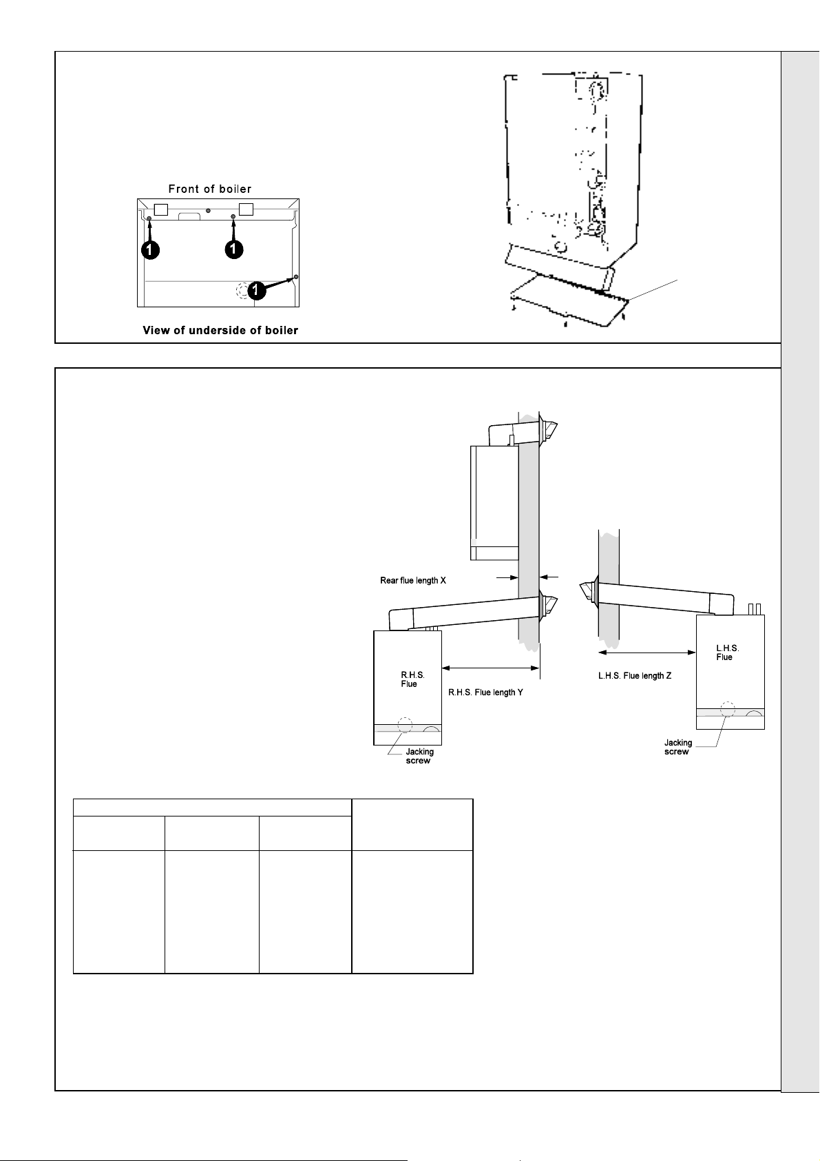
14
DETERMINING THE FLUE LENGTH AND FLUE PACKS REQUIRED
INSTALLATION
Bottom
panel
INSTALLATION
IMPORTANT. The boiler MUST be installed in a vertical position
Dimension X - Wall thickness
Dimension Y - Wall thickness plus
boiler spacing (RHS)
Dimension Z - Wall thickness plus
boiler spacing (LHS)
Flue length dimension Flue
Rear flue Right hand side Left hand side packs
dimn. X flue dimn. Y flue dimn. Z required
FLUE KITS
114 - 732 mm 114 - 614 mm 114 - 698 mm Pack B, cut down
(4 1/2 - 28 3/4") (4 1/2 - 24 1/8" ) (4 1/2 - 27 1/2" ) as in Frames 18 & 26
732 - 1931 mm 614 - 1813 mm 698 - 1897 mm Pack B (1 off) and
(28 3/4 - 76") (24 1/8 - 71 3/8") (27 1/2 - 74 3/4") Pack D (1 off)
1931 - 3130 mm 1813 - 3012 mm 1897 - 3096 mm Pack B (1 off) and
(76 - 123 1/4") (71 3/8 - 118 5/8") (74 3/4 - 121 7/8") Pack D (2 off )
Notes.
0
1. The flue duct MUST be inclined at 2.5
to allow condensate to drain back into the boiler and out
through the condensate drain.
to the horizontal
Minimiser - Installation
Pack B - supplied as standard
Pack D - optional extension kit for side flue
or rear flue outlet.
Refer to 'Flue Extension Ducts'
2. If the front of the boiler is to be flush with the front of
300mm deep kitchen units then the optional stand-off
bracket kit should be used. Care must be taken when
cutting the ducts and marking the wall to suit this condition.
13
Page 14
INSTALLATION
15
FLUE ASSEMBLY - Exploded View
1. An optional flue duct extension kit is required for
wall thicknesses greater than 732mm
3/4"). Refer to Frame 14.
(28
2. When cutting the ducts
always use the cardboard
support cutting aid provided.
16
WALL MOUNTING TEMPLATE
Note. The template shows the positions for the fixing holes and
the flue hole centres for standard installation.
Care must be taken to ensure the correct holes are drilled.
4
5
7
3
1
2
LEGEND
6
1. Terminal.
2. Weather seal.
3. Duct assembly.
4. Flue Turret
5. Angle plate
6. No. 8 x 8 fixing screw
7. M5 x 10 pozi screws (4)
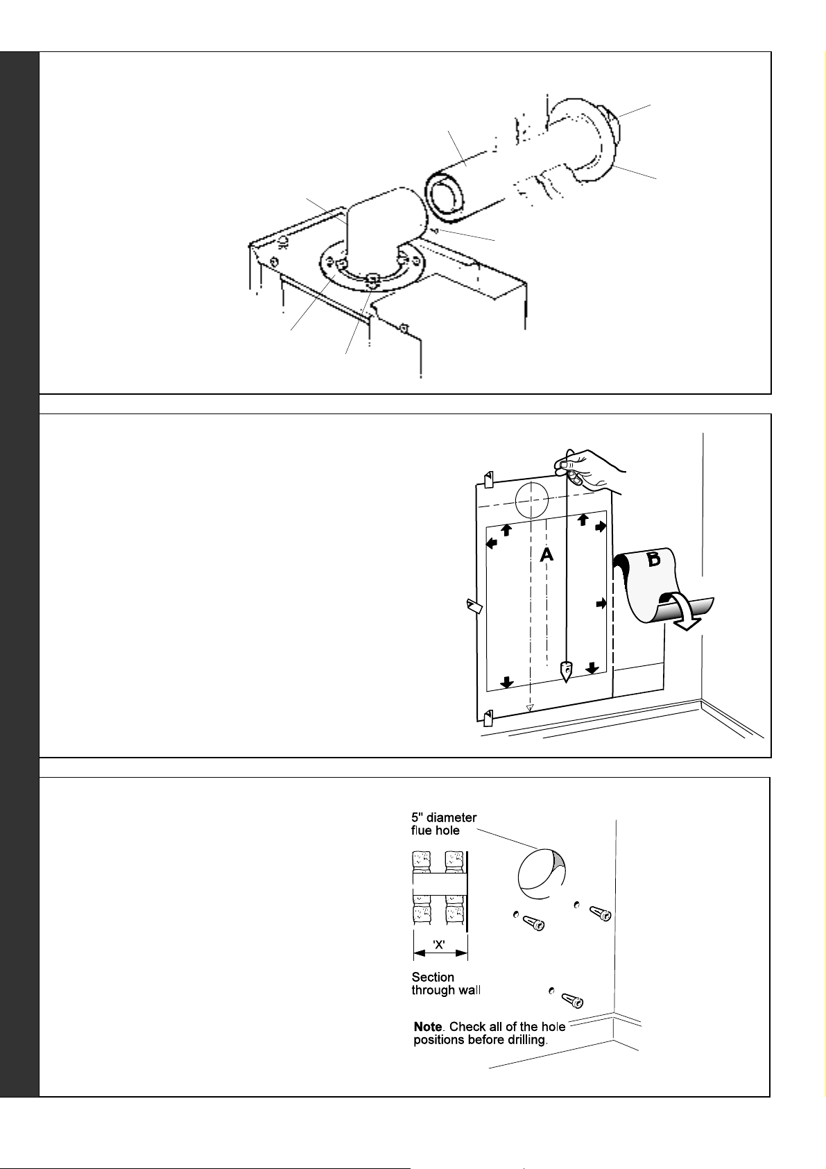
1. Separate the templates and discard template B.
2. Tape template into the selected position.
3. Ensure squareness by hanging a plumbline as shown.
4. Mark onto the wall the following:
a The plate screw positions (choose one from each group)
and lower fixing screw position.
b The position of the flue duct hole.
Note. Mark the centre of the hole as well as the
circumference
5. Remove the template from the wall.
17
PREPARING THE WALL
IMPORTANT. Ensure that, during the cutting operation,
masonry falling outside of the building does not cause damage
or personal injury.
1. Cut the flue hole (preferably with a 5" core boring tool),
ensuring that the hole is square to the wall.
Both wall faces immediately around the cut hole should be
flat.
2. Drill 3 holes with a 7mm (1/4") masonry drill and insert the
plastic plugs provided, for the wall mounting plate and the
jacking screw plate.
3. Locate two No.10 x 2" screws in the wall mounting plate
(one at each side, in any of the 3 holes provided at each
side) and screw home.
REAR FLUE OUTLET
Note. If the
terminal is to be
sited within 2540mm of a
corner or
vertical pipe
(refer to Table
3) then the hole
MUST be
accurately cut
and the rubber
weather seal
trimmed around
the groove
provided.
The terminal
wall plate need
not be fitted.
14
Minimiser - Installation
Page 15

18
CUTTING THE FLUE Wall thicknesses of 114 to 600mm
Note.
If the optional standoff bracket kit is used it is essential that
30 mm is added to the measured wall thickness when
marking the flue (to allow for the thickness of the brackets).
1. Measure and note wall thickness X.
INSTALLATION
2. Add 61mm (2
the groove, cut the tube.
3. To ensure the tube is cut square, mark the flue all the
way round.
4. Cut to length, using the cardboard support aid.
5. Remove the cardboard support and any burrs.
19
ASSEMBLING THE FLUE
1. Using the tube of sealant provided, apply sealant right round
the inside of the flue tube on the turret.
2. Fit the 'cut to length' flue on to the flue turret.
Note.
Ensure the groove in the flue aligns with the top of the turret.
3. Drill a 3.2mm dia. hole through the hole provided in the turret
and through the outer flue duct.
4. Using the self tapping screw provided, fix the flue assembly
to the turret.
3/8") to dimension X and, measuring from
cardboard
support cutting aid
20
MOUNTING THE BOILER
1. Lift the boiler onto the wall mounting plate, as
shown.
2. Check the boiler alignment using a spirit level
and adjust as necessary with the jacking
screw.
3. Align the hole in the jacking plate with the predrilled hole in the wall and fix in position with
the No.10 x 2" screw provided.
Note.
If the front of the boiler is to be flush with the front
of 300mm deep kitchen units then the optional
stand-off bracket kit should be used - refer to the
fitting instructions supplied with the kit.
Minimiser - Installation
REAR FLUE OUTLET
15
Page 16

INSTALLATION
21
CONNECTING THE FLUE TO THE BOILER
sealing panel
clips
Heat
exchanger
1. Undo the three clips retaining the
boiler sealing panel.
2. Swing the panel open to the left and
disengage it from the boiler.
3. Fit the flue connector tube (supplied
in the hardware pack) to the top of
the heat exchanger, ensuring that
the seal is in place.
4. Insert the flue assembly through the
hole in the wall far enough to allow
the rubber seal to unfold completely
and form an adequate seal on the
outside wall.
5. Pull the flue back and locate the flue
turret on to the top of the boiler, sealing
between the turret and the connector tube
with the sealant provided.
22
TERMINAL WALL PLATE
This plate allows neat concealment and full compression of
the rubber seal. Its use is not essential if the flue hole and
flue ducts have been accurately cut and the outside wall face
is flat.
1. Position the terminal wall plate over the terminal.
2. Drill 4 fixing holes with a 7mm (
3. Insert the 4 plastic plugs provided.
4. Secure the plate with 4 of the No.10 x 2" screws provided.
Note. If the terminal is less than 2m (6' 6") above ground
level, an approved terminal guard should be fitted.
Refer to 'Flue Installation', Page 5.
1/4") masonry drill.
6. Secure the flue turret assembly on the top
of the boiler using four M5 x 10mm screws
provided in Pack B.
Note. It is now necessary to make good
the inside wall face around the flue.
PROCEED TO FRAME 34
REAR FLUE OUTLET
16
Minimiser - Installation
Page 17

23
FLUE ASSEMBLY - Exploded view
1. An optional flue duct extension kit is
required for wall thicknesses greater than :
INSTALLATION
3
6
1
698 mm (27
614 mm (24
(see Frame 14).
2. When cutting the ducts
always use the
cardboard support
cutting aid provided.
24
WALL MOUNTING TEMPLATE
Note.
The template shows the positions for the fixing holes and
the flue hole centres for standard installation and for using
the standoff brackets. Care MUST be taken to ensure the
correct holes are drilled.
1/2") for RHS flue
1/8") for LHS flue
4
2
LEGEND
1. Terminal
2. Weather seal
3. Duct assembly
4. Angle plate
5
7
5. Flue turret
6. No.8 x 8 fixing screw
7. M5 x 10 pozi screws (4)
1. Separate the templates.
2. Tape both templates into the selected position, locating
template B through an extended centre line as shown ensure that it is the right way up for the flue hand
required.
3. Ensure squareness by hanging a plumbline as shown.
4. Mark onto the wall the following:
a The two wall mounting plate screw positions (choose
one from each group) and the jacking screw position.
b The position of the flue duct hole (see diagram below,
and template)
Note.
Mark the centre of the hole as well as the circumference
5. Remove both templates from the wall.
Note.
If the boiler is to be fitted flush with 300mm
kitchen units using the stand-off brackets
ensure the wall is marked to suit this
condition (the dotted flue hole outlines on
the template).
SIDE FLUE OUTLET
Minimiser - Installation
17
Page 18

INSTALLATION
25
PREPARING THE WALL
IMPORTANT. Ensure that, during the cutting operation, masonry
falling outside of the building does not cause damage or personal
injury.
1. Cut the flue hole (preferably with a 5" core boring tool), ensuring
that the hole is square to the wall. Both wall faces immediately
around the cut hole should be flat.
2. Drill 3 holes with a 7mm (
plugs, provided, for the wall mounting plate and the jacking
screw plate.
Note. If the terminal is to be sited within 25-40mm of a corner or
vertical pipe (refer to Table 3) then the hole MUST be accurately
cut and the rubber weather seal trimmed around the groove
provided. The terminal wall plate need not be fitted.
3. Locate 2 of the No.10 x 2" screws in the wall mounting plate (1 at
each side, in any of the 3 holes provided at each side) and screw
home.
26
CUTTING THE FLUE - For flue lengths 114 to 600mm ONLY
1. The flue cut length is calculated as follows:-
a. Measure and note the wall thickness X
b. Add dimension H, measured in Frame 24.
c. For right hand side flue add 181mm (7 1/8")
d. For left hand side flue add 96mm (3 3/4")
i.e. X + H + 181mm (7
X + H + 96mm (3 3/4") for LHS
2. Measure from the groove and cut the tube.
3. To ensure the tube is cut square, mark the flue
SIDE FLUE OUTLET
all the way round.
4. Cut to length, using the cardboard support aid.
5. Remove the cardboard support and remove
any burrs.
1/4") masonry drill and insert the plastic
1/8") for RHS
FOR FLUE LENGTHS GREATER THAN 600mm REFER TO FRAMES 31, 32 & 33 - FLUE EXTENSION DUCTS
27
ASSEMBLING THE FLUE
1. Using the tube of sealant provided, apply sealant right
round the inside of the flue tube on the turret.
2. Fit the 'cut to length' flue on to the flue turret.
Note.
Ensure the groove in the flue aligns with the top of the
turret.
3. Drill a 3.2mm dia. hole through the hole provided in the
turret and through the outer flue duct.
4. Using the self tapping screw provided, fix the flue
assembly to the turret.
18
cardboard support cutting aid
Minimiser - Installation
Page 19

MOUNTING THE BOILER
28
1. Lift the boiler onto the wall mounting plate, as shown.
2. Check the boiler alignment using a spirit level and adjust
as necessary with the jacking screw.
3. Align the hole in the jacking plate with the pre-drilled hole
in the wall and fix in position with the No.10 x 2" screw
provided.
Note. If the front of the boiler is to be flush with the front of
300mm deep kitchen units then the optional stand off bracket
kit should be used - refer to the fitting instructions supplied
with the kit.
29
CONNECTING THE FLUE TO THE BOILER
INSTALLATION
Clips
Sealing
panel
1. Undo the three clips retaining the boiler sealing panel.
2. Swing the panel to the left and disengage it from the boiler.
Heat
exchanger
SIDE FLUE OUTLET
3. Fit the flue connector tube (supplied in the hardware
pack) to the top of the heat exchanger, ensuring that
the seal is in place.
4. Insert the flue assembly through the hole in the wall
far enough to allow the rubber seal to unfold
completely and form an adequate seal on the outside
wall.
Minimiser - Installation
5. Pull the flue back and locate the flue turret on to the
top of the boiler, sealing between the turret and
connector tube, with the sealant provided.
6. Secure the flue turret assembly on the top of the
boiler, using four of M5 x 10mm screws provided in
Pack B.
Note.
It is now necessary to make good the inside wall face
around the flue
19
Page 20

INSTALLATION
30
TERMINAL WALL PLATE
This plate allows neat concealment and full compression of the
rubber seal. Its use is not essential if the flue hole and flue
ducts have been accurately cut and the outside wall face is flat.
1. Position the terminal wall plate over the terminal.
2. Drill 4 fixing holes with a 7mm (
3. Insert the 4 plastic plugs provided.
4. Secure the plate with 4 of the No.10 x 2" screws provided.
Note. If the terminal is less than 2m (6' 6") above ground level,
INSTALLATION
an approved terminal guard should be fitted. Refer to the Flue
Installation, Page 5.
31
FLUE EXTENSION DUCTS - For flue lengths greater than 600mm
1/4") masonry drill.
PACK D FLUE EXTENSION DUCT KIT CONTENTS.
32 FLUE EXTENSION DUCTS - continued
Use a maximum of two extension ducts only
General arrangement
Note. Side flue shown
maximum of two extension ducts (plus
1. A
the standard flue duct) may be used
together.
2. Flue extensions of greater length than 1m
(39") should be supported with the bracket
provided.
20
Minimiser - Installation
Page 21

33
FITTING THE KIT
IMPORTANT. At each joint, seal the inner flue tube, using the
sealant provided.
Note. Remove the cardboard support aid from the end of the
standard flue duct (Pack B).
1. Remove the flue extension tube from the flue and place
safely to one side.
2. Fit the flue extension connector on to the standard flue
duct.
INSTALLATION
3. Drill three 3.2mm dia. equally spaced holes through the
flue connector and the outer flue duct. Do not drill the
inner flue duct.
4. Insert the self tapping screws, provided, to fix the
connector in position.
5. Fit the inner flue duct into the connector.
6. Fit the outer flue duct into the connector.
7. Drill three 3.2mm dia equally spaced holes through the flue
connector and the outer flue duct. Do not drill the inner
flue duct.
8. Insert the self tapping screws, provided, to fix the
connector in position.
9. Repeat steps 5 - 8 if a second flue extension duct is
required.
10. Measure and mark the flue length required onto the flue,
measuring from the groove near the terminal.
11. To ensure the tube is cut square, mark the flue all the way
round.
INSTALLATION
12. Cut to length, using the cardboard support aid.
13. Remove the cardboard support and any burrs.
Appliances fitted with a REAR outlet flue; please refer to Frame 19
Appliances fitted with a
34
ELECTRICAL CONNECTIONS
WARNING. This appliance MUST be efficiently earthed
A mains supply of 230 V ~ 50 Hz is required.
All external controls and wiring MUST be suitable for mains
voltage. Wiring should be 3 core PVC insulated cable NOT
LESS than 0.75 mm2 (24 x 0.2mm) and to BS. 6500, Table 16.
SIDE
outlet flue; please refer to Frame 27
Wiring external to the boiler MUST be in accordance with the
current I.E.E. (BS7671) Wiring Regulations and any local
regulations.
The supply connection is intended to be made via a double
pole switch, having a 3mm (
poles, serving only the boiler and system controls.
The fuse rating should be 3 A.
1/8") contact separation in both
Minimiser - Installation
21
Page 22

INSTALLATION
35
INTERNAL WIRING
Note. If the programmer kit is to be fitted refer to the instructions provided with the kit, and Frame 36.
Incoming mains wiring detail
A pictorial wiring diagram is shown in Frame 37 .
1. Route the mains cable into the bottom RHS rear of the casing.
2. Swing the terminal strip bracket out.
3. Wire the live and neutral into the terminal strip.
4. Connect the earth wire to the earth post.
Note. Ensure that the lengths of the current carrying conductors are
shorter than the earth conductor so that if the cable slips in its
INSTALLATION
anchorage the current carrying conductors become taut before the
earth conductor.
5. Secure the mains lead with the cable clamp.
6. Swing the terminal strip bracket back into its working position.
Flow wiring diagram
LEGEND
b - blue
bk - black
br - brown
r - red
o - orange
w - white
y - yellow
36
EXTERNAL WIRING
External wiring MUST be in accordance with the current I.E.E.
(BS7671) Wiring Regulations.
The wiring diagrams illustrated in Frames 38 to 41 cover the
systems most likely to be used with this appliance.
For wiring external controls to the Minimiser boiler, reference
should be made to the systems wiring diagram supplied by the
relevant manufacturer in conjunction with the wiring diagrams
shown in Frames 38 to 41.
Difficulty in wiring should not arise, providing the following
directions are observed:
1. Controls that switch the system on and off, e.g. a time
switch, MUST be wired in series, in the live mains lead to
the boiler.
22
2. Controls that override an on/off control, e.g. a frost
thermostat, MUST be wired into the mains supply, in
parallel, with the controls to be overridden. Refer to
Frame 42.
3. If a proprietary system is used, follow the instructions
supplied by the manufacturer.
4. The pump must always be wired in parallel with the boiler.
5. SYSTEM DESIGNS FEATURING CONTROLS OR
WIRING ARRANGEMENTS WHICH ALLOW THE BOILER
TO FIRE WHEN THERE IS NO PUMPED CIRCULATION
TAKING PLACE MUST NOT BE FITTED.
Advice on required modifications to wiring may be obtained
from the component manufacturers.
Minimiser - Installation
Page 23

37
PICTORIAL WIRING
LEGEND
b - blue
bk - black
INSTALLATION
br - brown
r - red
w - white
or - orange
y - yellow
g/y - green/yellow
38
MID POSITION VALVE - pumped only
1. Some earth wires are omitted for clarity. Ensure
proper earth continuity when wiring
2. This is a fully controlled system - set the boiler
thermostat to MAXIMUM.
INSTALLATION
3. Numbering of thermostat terminals applies only to
the manufacturer mentioned.
LEGEND
b - blue
bk - black
br - brown
r - red
y - yellow
w - white
g/y - green/yellow
gy - grey
or - orange
v - violet
pk - pink
Minimiser - Installation
23
Page 24

INSTALLATION
39
DIVERTER VALVE - pumped only
1. Some earth wires are omitted for clarity -
ensure proper earth continuity when wiring.
2. This is a fully controlled system - set the boiler
thermostat to MAXIMUM.
3. Numbering of thermostat terminals applies
only to the manufacturer mentioned.
4. The boiler should be sized for radiator load
only.
5. A clock 'stat may be used instead of separate
room 'stat and time switch.
INSTALLATION
LEGEND
b - blue
br - brown
bk - black
40
ONE VALVE IN HEATING CIRCUIT - pumped only
1. Some earth wires are omitted for clarity - ensure
proper earth continuity when wiring.
2. Numbering of thermostat terminals applies only
to the manufacturer mentioned.
LEGEND
b - blue
bk - black
br - brown
r - red
y - yellow
w - white
g/y - green/yellow
gy - grey
or - orange
v - violet
pk - pink
r - red
y - yellow
w - white
g/y - green/yellow
24
Minimiser - Installation
Page 25

41
TWO SPRING CLOSED VALVES - pumped only
1. Some earth wires are omitted for clarity -
ensure proper earth continuity when wiring.
2. This is a fully controlled system - set the
boiler thermostat to MAXIMUM.
3. Numbering of thermostat terminals applies
only to the manufacturer mentioned.
LEGEND
INSTALLATION
b - blue
bk - black
br - brown
r - red
y - yellow
w - white
g/y - green/yellow
gy - grey
or - orange
v - violet
pk - pink
42
FROST PROTECTION
Central heating systems fitted wholly inside the house do not
normally require frost protection as the house acts as a
'storage heater' and can normally be left at least 24 hours
without frost damage.
INSTALLATION
However, if parts of the pipework run outside the house or if
the boiler will be left off for more than a day or so then a frost
thermostat should be wired into the system. This is usually
done at the programmer, in which case the programmer
selector switches are set to OFF and all other controls MUST
be left in the running position.
The frost thermostat should be sited in a cold place but
where it can sense heat from the system.
Wiring should be as shown, with minimal disturbance to other
wiring of the programmer.
Designation of the terminals will vary but the programmer
and thermostat manufacturers' leaflets will give full details.
Diagram A shows a double-pole frost thermostat, which
should suffice for all systems which do not use the OFF
terminals of the programmer.
Diagram B shows a 'changeover' frost thermostat, which will
cover most systems which do use CH OFF. If, however, on
such a system the HW pipework is in an isolated part of the
house a second frost thermostat may be used to protect it. If
in doubt ask your installer for advice.
Note.
If the boiler is installed in a garage it may be
necessary to fit a pipe thermostat.
Minimiser - Installation
25
Page 26

INSTALLATION
43
BOILER WATER CONNECTIONS
The boiler flow and return pipes are supplied fitted to the boiler and ready for top connection.
Note. For boiler sizes FF30 to FF60 use the 28mm x 22mm connectors
supplied in the hardware pack, to reduce the boiler flow and return
pipes to 22mm.
2
TOP CONNECTION
Connect the system pipework to the boiler flow and return pipes.
BOTTOM CONNECTION
1. Remove the retaining pin and withdraw the thermostat phial from
the pocket.
INSTALLATION
2. Disconnect the electrical leads from the overheat thermostat.
3. Undo the flow and return pipe unions and withdraw the pipes from
the boiler.
4. Cut off the spun ends of the pipes and connect pipes of suitable
length to terminate 50mm (2") outside the bottom of the boiler
casing.
5. Refit the pipe assemblies to the flow and return bosses, ensuring
that the gaskets are in position.
Note. Fit the return pipe assembly first.
1
6
3
4
6. Fit an automatic air vent to the top of the return pipe assembly
and a manual air vent to the top of the flow pipe assembly (where
pressures may at times be negative).
7. Connect the system pipework to the flow and return pipes at the
bottom of the boiler.
8. Reconnect the overheat thermostat electrical leads and re-insert
the boiler thermostat phial into the pocket, retaining it with the split
pin.
44
CONDENSATE DRAIN
Refer also to the British Gas document: 'Guidance Notes for
the Installation of Domestic Gas Condensing Boilers' (1989)
Centre line of boiler
Pipework shown as a dotted line is not supplied
The routing of the drain must be made to allow a minimum
fall of 1 in 20 away from the boiler, throughout its length.
The drainage pipework must be arranged so that
obstruction (e.g. through freezing) of external drainage pipe
does not give rise to spillage within the dwelling.
Important. Any external runs must be insulated.
Excessive external pipe runs should be avoided in order to
prevent possible freezing.
All pipework and fittings in the condensate drain system
must be made of plastic. No other materials may be used.
The drain outlet on the boiler is standard 22mm overflow
pipe. This size must not be reduced in any part of its
length.
Condensate drain
Note.
145 mm
The drain connection is located at the rear of the controls compartment
The condensate drain provided on the boiler must be
connected to a drainage point, preferably within the building.
(72 mm
42 mm
with stand-off bracket)
26
In order to defer the onset of freezing of the condensate
drain when the pipe is run externally the pipe should be run
as far as possible within the building.
The boiler condensate drain connection is suitable for Bartol
'Polypipe' tubing. An adaptor is supplied to allow the use of
Marley 'Terrain' tubing, which is slightly larger. This adaptor
should be sealed to the Marley 'Terrain' tubing and to the
boiler condensate drain, using a suitable plastic tube
adhesive.
Minimiser - Installation
Page 27

INSTALLATION
45
GAS CONNECTION
Refer to Frame 2 for details of the position of the gas onnection.
A MINIMUM working gas pressure of 20 mbar (8" w.g.) must be
available at the boiler inlet with the boiler firing. Refer to Frame
47 or 'Servicing' for details of the pressure test point position.
Extend a gas supply pipe NOT LESS THAN 15mm O.D. to the
boiler and connect to the gas service cock, situated at the
bottom right hand side of the boiler.
The connection MUST be from the RHS rear of the boiler and
from either ABOVE or BELOW. Do not route the pipe behind the
control box.
Ensure that the gas supply pipe does not foul the boiler casing.
Note. If the pipe run from the meter to the boiler is greater
than 3m (10') it is recommended that 22mm O.D. pipe is used.
To facilitate connection, it is recommended that the gas service
cock is not removed from the gas control valve.
A 1/2" BSP x 15mm connector, pre-fitted with a short stub
connection, should be screwed into the cock, using a suitable
sealant.
IMPORTANT. The gas service cock contains a non-metallic
seal so must not be overheated when making capillary
connections.
46
COMMISSIONING AND TESTING
A. Electrical Installation
1. Checks to ensure electrical safety should be carried out by a
competent person.
2. ALWAYS carry out the preliminary electrical system checks, i.e.
earth continuity, polarity, resistance to earth and short circuit,
using a suitable test meter.
WA
RNING. Whilst effecting the required gas soundness test and purging air from the gas installation, open all windows and doors, extinguish
naked lights and DO NOT SMOKE.
B. Gas Installation
1. The whole of the gas installation, including the meter, should be
inspected and tested for soundness and purged in accordance
with the recommendations of BS. 6891.
2. Purge air from the gas installation by loosening the gas cock
union and purge until gas is smelled.
3. Retighten the union and test for gas soundness.
INSTALLATION
47
INITIAL LIGHTING
LEGEND
A 'Burner on' neon
B Thermostat knob
C Gas service cock
D Inlet pressure test point
E Burner pressure test point
F Burner pressure adjuster
1. Check that the system has been filled and that the boiler is not air
locked - air in the system could trip the dry fire 'stat (H)
2. Check that all the drain cocks are closed and any valves in the flow
and return are open.
3. Check that the electrical supply is OFF.
4. Check that the flue 'stat (L) is calling for heat - press the reset
button.
5. Refit the boiler sealing panel - refer to Frame 21.
6. Check that the gas service cock (C) is ON and that the boiler
thermostat knob (B) is OFF.
7. Check that the dry fire thermostat (H) and overheat thermostat (J)
are calling for heat - press the reset buttons.
8. Remove the screw in the burner pressure test point (E) and connect
a gas pressure gauge via a flexible tube.
9. Switch the electricity supply ON and check that all external controls
are calling for heat.
10. Set the boiler thermostat knob (B) to position 6. The gas control
solenoid valve should open and the spark commence, continuing
until the burner is established.
11. Check that the burner lights smoothly and that the 'Burner on' neon
(A) illuminates.
If this does not occur within 10 seconds, turn the thermostat knob to
OFF, wait for 5 seconds then repeat step 10.
If the burner still does not light refer to the 'Fault Finding' section.
12. Test for gas soundness around ALL boiler gas components, using
leak detection fluid.
13. Operate the boiler for 20 minutes to stabilise the burner
temperature.
G Fan pressure test point (Hi)
H Dry fire thermostat reset button
I Fan pressure test point (Lo)
J Overheat thermostat reset button
K Flue gas sampling point
L Flue 'stat reset button (behind
sealing panel)
Note. Boiler is shown with the front panel removed and the controls
drop down door open
K
J
L
I
G
H
F
E
D
C
B
A
14. The boiler is spot rated. Check that the burner pressure
corresponds to the setting given on the data plate, located at the
RHS of the boiler casing. Adjust as necessary via the adjuster
screw (F). Prise aside the plastic cover and turn the screw
CLOCKWISE to reduce the pressure or ANTICLOCKWISE to
increase the pressure. Refit the cover.
15. Set the thermostat knob (B) to OFF.
16. Switch the electricity supply OFF.
17. Remove the pressure gauge and tube. Replace the sealing screw
in the pressure test point. Ensure a gas tight seal is made.
18. Refit the boiler front and bottom panels, using the screws
previously removed.
19. Close the controls pod door.
Minimiser - Installation
27
Page 28

INSTALLATION
48
GENERAL CHECKS
Make the following checks for correct operation
1. Operate the thermostat knob and check that the burner and 'Burner on' neon, light and extinguish in response.
2. The correct operation of ANY programmer and all other system controls should be proved. Operate each control separately
and check that the main burner or circulating pump, as the case may be, responds.
3. Water circulation system:
Note. Fernox Superfloc flushing solution should be used during the flushing procedure - refer to Frame 9.
a. With the system HOT examine all water connections for soundness.
b. With the system still HOT, turn off the gas, water and electricity supplies to the boiler and drain down to complete the
flushing process.
INSTALLATION
c. Refill and vent the system, add inhibitor (see Frame 9), clear all air locks and again check for water soundness.
Adhere the water treatment warning label, supplied in the hardware pack, in a prominent position on the system, to
prevent the use of incorrect water treatment additives.
d. Balance the system (see Frame 4).
4. Check the condensate drain for leaks and check that it is
discharging correctly
5. Finally set the controls to the User’s requirements.
• If an optional programmer kit is fitted then refer to the
instructions supplied with the kit.
• The temperatures quoted alongside are approximate, and
vary between installations.
49
HANDING OVER
After completing the installation and commissioning of the
system the installer should hand over to the householder by
the following actions:
1. Hand the User's Instructions to the householder and
explain his or her responsibilities under the Gas Safety
(Installation and Use) Regulations 1994.
2. Draw attention to the Lighting Instruction label affixed to the
controls pod door.
Knob Setting Flow Temperature
°C °F
1 50 120
2 60 140
3 66 150
4 71 160
5 77 170
6 82 180
Advise the User of the precautions necessary to prevent
damage to the system and to the building in the event of
the system remaining inoperative during frosty conditions.
5. Explain the function and the use of the boiler thermostat
and external controls.
6. Explain and demonstrate the function of time and
temperature controls, radiator valves, etc., for the
economic use of the system.
3. Explain and demonstrate the lighting and shutting down
procedures.
4. The operation of the boiler and the use and adjustment of
ALL system controls should be fully explained to the
householder to ensure the greatest possible fuel economy
consistent with household requirements of both heating and
hot water consumption.
28
7. If any programmer kit is fitted then draw attention to the
Programmer Kit User's Instructions and hand them to the
householder.
8. Stress the importance of regular servicing by a Corgi
registered installer and that a comprehensive service
should be carried out AT LEAST ONCE A YEAR.
Minimiser - Installation
Page 29

SERVICING SCHEDULE
50
To ensure the continued safe and efficient operation of the
appliance it is recommended that it is checked at regular
intervals and serviced as necessary. The frequency of
servicing will depend upon the installation condition and usage
but should be carried out at least annually. It is the law that
any service work must be carried out by a registered CORGI
installer.
1. Remove the boiler bottom panel - refer to Frame 59,
step 4.
2. Light the boiler and carry out a pre-service check, noting
any operational faults.
3. Check the operation of the pressure switch - refer to Frame
51.
4. Relight the boiler and operate for at least 20 minutes.
Check the gas consumption.
5. Connect a suitable gas analyser to the sampling point on
top of the boiler - refer to Frame 51 (optional test).
For correct boiler operation the CO/CO
gas should not be greater than 0.004 ratio.
If this is the case, and the gas input is at least 90% of the
nominal, then no further action need be taken. If not,
proceed to step 6.
6. Clean the main burner.
content of the flue
2
SERVICING
7. Clean the heat exchanger.
Note. This must be done with the heat exchanger and
deposits in a dry condition - refer to Frame 55.
8. Check the main injector for blockage or damage.
9. Check that the flue terminal is unobstructed and that the
flue system is sealed correctly.
The servicing procedures are covered more fully in Frames
51 to 57 and MUST be carried out in sequence.
WARNING. Always turn off the gas supply at the gas service
cock, and switch off and disconnect the electricity supply to
the appliance before servicing.
IMPORTANT. After completing the servicing or exchange of
components always test for gas soundness and carry out
functional checks as appropriate.
Note. In order to carry out either servicing or replacement of
components the boiler front panel and sealing panel must be
removed - refer to Frames 12 and 52.
IMPORTANT. When work is complete the sealing panel
MUST be correctly refitted, ensuring that a good seal is made.
DO NOT OPERATE THE BOILER IF THE SEALING PANEL
IS NOT FITTED.
51
PRESSURE SWITCH OPERATION
1. Connect a flexible tube to the pressure switch tapping,
located at the bottom of the boiler, behind the control box.
Flue gas
sampling point
Control box
Flexible
tube
Pressure
switch tapping
52
BOILER SEALING PANEL REMOVAL
1. Turn off the gas supply at the gas service cock and
disconnect the electricity supply.
Retaining clips
SERVICING
2. With the boiler running, blow gently into the tube. The
burner should shut down and the 'Burner on' neon
extinguish. The fan should continue to run. If this does
not occur replace the pressure switch - refer to Frame 71.
3. Remove the flexible tube and refit the boiler bottom panel.
Note. The pressure switch tapping does not have a cap or
sealing screw and MUST be left open to atmosphere.
Minimiser - Installation
2. Remove boiler front panel as described in Frame 12.
3. Release the three retaining clips on the right hand side
of the panel.
4. Swing the panel open to the left and disengage it from
the boiler.
29
Page 30

SERVICING
53
FAN REMOVAL AND CLEANING
1. Disconnect the electrical leads from the fan.
2. Disconnect the pressure sensing pipe from the fan.
a. Undo the 2 screws securing the pipe to the fan.
b. Undo the 2 screws securing the pipe clamping plate to the
manifold block.
c. Withdraw the clamping plate.
d. Withdraw the pipe from the boiler.
3. Press the retaining bracket lever upwards and rotate the fan
body to the right to disengage the fan scroll from the bracket.
Continue rotating to disengage the bayonet fixing on the fan
outlet.
4. Withdraw the fan.
5. Check that the fan impeller runs freely. Clean with a soft
brush or renew as necessary - refer to Frame 70.
Note. Always take care when handling the fan, in order to
preserve the balance of the impeller.
54
BURNER REMOVAL AND CLEANING
(a)
Manifold
block
Gasket
Clamping
plate
3
(d)
Fan pressure
sensing pipe
(c)
(b)
Burner pressure sensing pipe
1. Disconnect the 2 ignition leads and one detection lead from
the electrodes.
2. Disconnect the pressure sensing pipe from the burner. Pull
the pipe downward to disengage it from the burner
mounting plate.
3. Undo the 3 fixing screws securing the burner assembly.
SERVICING
4. Withdraw the burner assembly downward and out of the
heat exchanger.
5. Brush off any deposits that may have collected on the
burner, ensuring that the flame ports are unobstructed.
Note. Brushes with metallic bristles MUST NOT be used.
6. Inspect the spark and detection electrodes. Ensure they
are clean and in good condition - replace if necessary.
7. Check the spark and electrode gaps are correct.
8. Check that the spark and detection leads are in good
condition and renew as necessary
55
CLEANING THE HEAT
EXCHANGER
Dimensions in mm.
3
Spark
electrodes
Detection electrode
IMPORTANT. Deposits are most effectively removed
from the fins if they are dry. Ensure this by running
the pre-service checks with the boiler thermostat set
to maximum to avoid condensing conditions.
1. Place a plastic sheet or similar beneath the boiler
and remove all visible loose deposits from the
heat exchanger fins, using a suitable brush.
2. Take care to clean debris from the ledge inside
the combustion chamber.
30
Minimiser - Installation
Page 31

56
RE-ASSEMBLY
SERVICING
Reassemble the boiler in the following order:
1. Refit the burner, renewing any damaged or
deteriorating sealing gaskets.
2. Reconnect the 2 ignition leads and the detection lead.
3. Reconnect the pressure sensing pipe to the burner.
4. Refit the fan, engaging it in the bayonet fixing and
locating it in the retaining bracket.
Ensure that the O ring seal is in place.
5. Reconnect the pressure sensing pipe to the fan and
secure both pipes to the manifold block with the
clamping plate.
6. Reconnect the fan electrical leads.
7. Refit the boiler sealing panel.
IMPORTANT. Ensure the boiler sealing panel is
correctly fitted and that a good seal is made.
8. Refit the boiler front panel.
9. Turn on the gas supply at the gas service cock.
10.Reconnect the electrical supply.
Note. The fan and burner pressure sensing pipes must be tested for gas soundness
57
BURNER PRESSURE CHECK
After any servicing, reference should be made to Table 2, page 3 (or the data plate), which quote details
of the burner pressures for the boiler models.
The burner pressure should be checked against these values and adjusted accordingly - refer to 'Initial
Lighting', Frame 47.
If the burner pressure is very low check the fan pressure - refer to Fault Finding Frame 82.
REPLACEMENT OF COMPONENTS
58
GENERAL
WHEN REPLACING ANY COMPONENT
1. Isolate the electricity supply
2. Turn off the gas supply.
3. Remove the boiler front panel and sealing panel - refer to Frames 12 and 52.
IMPORTANT. When work is complete the sealing panel must be correctly fitted, ensuring that a good seal is made.
Note.
In order to assist fault finding, the control box printed circuit board is fitted with three indicator lights which represent the
following boiler conditions - refer to Frame 72.
SERVICING
LED 2 Lockout
LED 3 Fan on
LED 4 Mains electricity on
THE BOILER MUST NOT BE OPERATED IF THE SEALING PANEL IS NOT FITTED.
Minimiser - Installation
31
Page 32

SERVICING
59
CONTROL THERMOSTAT REPLACEMENT
5
Refer also to Frame 10 - 'Boiler exploded view' and Frame
37 'Pictorial wiring.'
1. Refer to Frame 58.
Note. The sealing panel need not be removed.
2. Remove the split pin and withdraw the thermostat phial
from the pocket - refer to Frame 60.
3. Release the thermostat capillary from its retaining clips.
4. Remove the boiler bottom panel.
a. Undo the three retaining screws.
b. Push the panel backward then to the right to
withdraw it from the boiler.
5. Pull off the thermostat knob.
6. Undo the control box retaining screw.
8
9
7. Push the control box back then drop the front of the
box. If access is restricted pull the control box forward
and remove.
8. Disconnect the thermostat electrical leads.
9. Undo the retaining nut and withdraw the thermostat.
10. Fit the new thermostat and reassemble in reverse order,
ensuring that the thermostat capillary is correctly routed.
60
OVERHEAT THERMOSTAT REPLACEMENT
Refer also to Frame 10 - 'Boiler exploded view' and Frame 37 'Pictorial wiring.'
SERVICING
1. Refer to Frame 58.
Note. The sealing panel need not be removed.
2. Disconnect the overheat thermostat electrical leads.
3. Undo the two securing screws and withdraw the thermostat.
4. Fit the new overheat thermostat and reassemble in reverse order.
61
DRY FIRE THERMOSTAT REPLACEMENT
4
2
Boiler flow pipe
Control
3
Refer also to Frame 10 'Boiler exploded view'.
1. Refer to Frame 58.
2. Disconnect the spark electrode leads.
3. Remove the fan assembly - refer to Frame 53.
4. Disengage the thermostat capillary from the
retaining clip.
5. Withdraw the thermostat phial from the pocket.
thermostat
capillary
6
Note. Take care not to damage the thermostat capillary
when inserting it into the pocket.
32
6. Disconnect the thermostat electrical leads.
7
7. Undo the thermostat retaining nut and withdraw the
thermostat.
8. Fit the new dry fire thermostat and reassemble in
reverse order.
Minimiser - Installation
Page 33

62
FLUE THERMOSTAT REPLACEMENT
Refer also to Frame 10 'Boiler exploded view' and Frame 37
'Pictorial wiring.'
1. Refer to Frame 58.
2. Disconnect the flue thermostat electrical leads.
3. Unscrew the thermostat from the side of the heat
exchanger.
4. Fit the new flue thermostat and reassemble in reverse
order.
SERVICING
63
SPARK AND DETECTION ELECTRODE REPLACEMENT
Refer also to Frame 10 'Boiler exploded view.'
1. Refer to Frame 58.
2. Remove the fan assembly - refer to Frame 53.
3. Remove the burner assembly - refer to Frame 65,
steps 3 to 6.
4. Disconnect the electrode leads as required.
5. Undo the electrode securing bracket screws as required.
6. Fit new electrodes as necessary, ensuring that the
gaskets are in good condition and sealing correctly renew as necessary.
7. Check the spark / detection gaps.
8. Reassemble in reverse order.
9. Check the ignition and operation of the burner.
Note. The spark electrodes are replaced as a pair; the detection electrode is a single probe.
64
SPARK GENERATOR REPLACEMENT
Detection
electrode
6
5
electrode
Dimensions in mm.
12 ± 1
4 ± 1
Spark
Burner
10 ± 1
SERVICING
Detection
electrode
2
1. Refer to Frame 58.
2. Disconnect the leads from the spark
electrodes
3. Disconnect the electrical leads from the spark
generator.
4. Undo the single screw fixing on the spark
generator
5. Fit the new spark generator and re-assemble
in reverse order.
6. Check the ignition and operation of the burner.
Minimiser - Installation
4
3
33
Page 34

SERVICING
65
BURNER REPLACEMENT
1. Refer to Frame 58.
2. Remove the fan assembly - refer to Frame 53.
3. Disconnect the 2 ignition leads and one detection lead
from the electrodes.
4. Disconnect the pressure sensing pipe from the burner.
Pull the pipe downward to disengage it from the burner
mounting plate.
5. Undo the 3 fixing screws securing the burner assembly
6. Withdraw the burner assembly downward and out of
the heat exchanger.
7. Remove the spark and detection electrodes - refer to
Frame 63.
8. Remove the 3 securing screws and withdraw the
burner from the mounting flange.
9. Fit the new burner, replacing any
damaged or deteriorating gaskets.
Note. There are 2 graphite gaskets
under the burner sensor casting. It
is IMPERATIVE that BOTH be
replaced before the burner is
refitted.
4
10. Reassemble in reverse order.
Note. Check the spark and
detection gaps - refer to Frame 63.
SERVICING
66
BURNER INJECTOR REPLACEMENT
Burner
8
Gasket
Graphite gaskets
(2 off)
Burner mounting
flange
5
1. Refer to Frame 58.
2. Remove the fan assembly - refer
to Frame 53.
Injector
34
Injection
pipe
3. Unscrew the injector from the
gas injection pipe.
4. Fit the new injector using a
suitable jointing compound
sparingly.
5. Reassemble in reverse order.
Minimiser - Installation
Page 35

67
GAS CONTROL VALVE REPLACEMENT
Refer also to Frame 10 - 'Boiler exploded view.'
1. Refer to Frame 58.
2. Remove the casing bottom panel - refer to Frame
59.
3. Remove the control panel.
a. Pull off the thermostat knob.
b. Undo the control box retaining screw - refer to
Frame 59.
c. Supporting the control panel, undo the two
retaining screws and withdraw the panel.
4. Remove the fan unit - refer to Frame 53.
SERVICING
5. Disconnect the burner pressure sensing pipe - refer to
Frame 65, step 4.
a
b
c
6. Undo the two retaining screws and unplug the electrical
leads from the gas valve.
SERVICING
7. Undo the gas cock union connection.
Inter panel
8. Undo the two extended nuts retaining the gas
injection pipe and withdraw the pipe, taking care
not to lose the O ring seal.
9. Supporting the valve, undo the three retaining screws and withdraw
the gas valve, complete with mounting bracket and manifold block.
Minimiser - Installation
Manifold block
35
Page 36

SERVICING
68
GAS CONTROL VALVE REPLACEMENT - continued
10. Undo the retaining nut and withdraw the manifold
from the gas valve mounting bracket.
11. Undo the 6 retaining screws and separate the gas
valve from the mounting bracket.
12. Transfer the bracket and manifold to the new gas
valve, ensuring that any damaged or deteriorating
gaskets are replaced.
Manifold block
13. Transfer the gas cock union to the new gas valve,
using a suitable approved jointing compound,
sparingly.
SERVICING
10
Mounting
bracket
14. Fit the new gas valve in reverse order,
ensuring that the gas injection pipe O
ring seal is refitted.
15. Check the operation of the new gas
valve.
16. Operate the boiler for at least 20
minutes and set the burner pressure to
the value shown on the data plate refer to Frame 47.
11
69
GAS CONTROL VALVE SOLENOID REPLACEMENT
Refer also to Frame 10 - 'Boiler exploded view'.
To replace either solenoid follow steps 1 - 6.
1. Refer to Frame 58.
Note. The sealing panel need not be removed.
2. Remove the control panel - refer to Frame 67.
3. Undo the retaining screw and unplug the electrical lead
from the solenoid.
4. Undo the 2 securing screws and remove the solenoid.
5. Fit the new solenoid and re-assemble in reverse order.
6. Check the operation of the new solenoid.
36
3
4
Solenoid
Minimiser - Installation
Page 37

70
FAN UNIT REPLACEMENT
Refer also to Frame 10 - 'Boiler exploded view'.
1. Refer to Frame 58.
2. Disconnect the electrical leads from the fan.
3. Disconnect the pressure sensing pipe from
the fan.
a. Undo the 2 screws securing the pipe to
the fan.
b. Undo the 2 screws securing the pipe
clamping plate to the manifold block.
c. Withdraw the clamping plate.
d. Withdraw the pipe from the boiler.
4. Press the retaining bracket lever upward and
rotate the fan body to the right to disengage
the fan scroll from the bracket. Continue
rotating to disengage the bayonet fixing on the
fan outlet.
5. Withdraw the fan.
Note. Always take care when handling the fan
in order to preserve the balance of the
impeller.
6. Fit the new fan in reverse order, ensuring that:
a. The O ring seal is correctly refitted.
b. The sensing pipe clamping plate is
correctly refitted.
7. Check the operation of the new fan.
4
(a)
Manifold
block
Gasket
Clamping
plate
(b)
SERVICING
3
(d)
Fan pressure
sensing pipe
(c)
Burner pressure sensing pipe
SERVICING
71
PRESSURE SWITCH REPLACEMENT
Refer also to Frame 10 - 'Boiler exploded view'.
1. Refer to Frame 58.
2. Remove the fan unit - refer to Frame 53.
3. Disconnect the pressure sensing pipe from the
switch, noting its position - tapping P1(+).
4. Disconnect the electrical leads from the switch,
noting their position. Connections are made to
terminals 1 and 3.
5. Undo the securing screw and withdraw the
switch.
6. Fit the new switch in reverse order
7. Check the operation of the new switch - refer
to Frame 51.
3
4
5
Minimiser - Installation
37
Page 38

SERVICING
72
PRINTED CIRCUIT BOARD REPLACEMENT
Refer also to Frame 10 - 'Boiler exploded view'. & Frame 37 - 'Pictorial wiring'.
1. Refer to Frame 58. Note. The sealing panel need not be removed.
2. Remove the boiler bottom panel - refer to Frame 59, step 4.
3. Open the controls pod door and pull off the thermostat knob.
4. Undo the control box securing screw and swing the box into the 'servicing'
position. If access if restricted pull the box forward and free from the boiler refer to Frame 59.
b
6
a
2
3
LED
6
d
c
Fuse
PCB
37
4
6. Squeeze the retaining tabs on the two location pins and
withdraw the PCB, complete with the other 2 pins.
Transfer these pins to the new PCB..
3
4
5. Unplug the following leads from the PCB:
e
a. Gas valve lead
b. Flame detection lead
c. 'Burner on' neon lead
d. Fan lead
e. Mains input lead
SERVICING
73
'BURNER ON' NEON REPLACEMENT
Refer also to Frame 37 - Pictorial Wiring.
1. Refer to Frame 58. Note. The sealing panel need not be
removed.
2. Swing the control box into its 'servicing' position - refer to
Frame 72, steps 1-4 .
74
CONDENSATE SIPHON REPLACEMENT
Refer also to Frame 10 - 'Boiler exploded view'.
1. Refer to Frame 58.
2. Remove the fan unit - refer to Frame 53.
3. Remove the gas injection pipe - refer to Frame 67, step 8.
4. Disconnect the spark and detector leads - refer to Frame 63.
5. Disconnect the condensate drain from the bottom of the boiler.
6. Undo the siphon union connection.
7. Fit the new PCB and re-assemble in reverse order.
Ensure that all electrical connections are correctly
remade.
8. Check the operation of the boiler.
3. Unplug the 'Burner on' neon lead from the PCB - refer to
Frame 72.
4. Prise the neon out of the lens holder.
5. Fit the new neon and re-assemble in reverse order.
6
Siphon
7. Push the siphon down slightly to clear the union, tilt
forward and withdraw it from the boiler.
8. Fit the new siphon and reassemble in reverse order,
replacing any damaged or deteriorating sealing gasket.
38
5
Minimiser - Installation
Page 39

75
HEAT EXCHANGER REPLACEMENT
IMPORTANT. Before starting the removal procedure, protect the gas and
electrical controls with a waterproof sheet or plastic bag.
14
SERVICING
15
Refer also to Frame 10 - 'Boiler exploded view'.
1. Refer to Frame 58.
2. Drain down the system.
3. Drain the heat exchanger via the drain point,
taking care to protect electrical components
from water.
4. Remove the fan assembly - refer to Frame
53.
5. Remove the burner assembly - refer to
Frame 65.
6. Remove the gas injection pipe - refer to
Frame 67.
7. Remove the spark generator - refer to Frame
64.
8. Remove the back retaining screw.
9. Withdraw the dry fire thermostat phial from
its pocket - refer to Frame 61.
10. Remove the condensate siphon - refer to
Frame 74.
Support
Boiler
Flow
Bosses
Flow pipe
16
Return pipe
11. Disconnect the flue gas sampling tube from
the top of the heat exchanger.
12. Remove the flue thermostat - refer to Frame
62.
13. Disconnect the boiler flow and return pipes
from the system pipework close to the boiler.
11
12
Heat exchanger
3 Return
8
14. Remove the control thermostat phial from its pocket - refer to
Frame 59.
15. Disconnect the overheat 'stat electrical leads.
16. Undo the flow and return pipe union nuts and pull the pipes clear
of the flow and return bosses.
17. Undo the four flow and return boss retaining screws.
18. While supporting the heat exchanger from below, withdraw the
bosses from the flow and return tappings.
If necessary, the bosses may be 'jacked' out by screwing the
retaining screws into the two threaded holes in each flange.
Check the O rings for damage and replace if necessary.
19. Lower the heat exchanger to disengage from the flue connector
tube, and withdraw it from the boiler.
20. Fit the new heat exchanger and re-assemble in reverse order.
IMPORTANT
The flow and return bosses are not common and MUST be refitted in
their correct positions.
18 17
SERVICING
Minimiser - Installation
The FLOW connection boss has a COARSE thread.
FINE
The RETURN connection boss has a
thread.
39
Page 40

SERVICING
76
BOILER SEALING PANEL SEAL REPLACEMENT
1. Refer to Frame 58.
2. Remove the old seal from the casing and
thoroughly clean the casing surfaces.
3. Fit the new self adhesive seals.
4. Re-assemble in reverse order.
Note.
Ensure that the boiler sealing panel is correctly seated,
compressing the sealing strip to make an airtight joint.
2
77
PROGRAMMER REPLACEMENT (IF FITTED)
1. Refer to Frame 58.
2. Remove the casing front panel - refer to Frame 12.
3. Remove the boiler bottom panel - refer to Frame 59,
step 4.
4. Disconnect the six leads from the back of the
programmer, noting their positions.
5. Remove the control panel - refer to Frame 67, step 3.
SERVICING
6. Undo the two retaining screws and withdraw the
programmer, complete with mounting bracket, from the
control panel.
7. Compress the clips on the sides of the programmer and
withdraw it from the retaining bracket.
8. Fit the new programmer and reassemble in reverse order.
9. Check the operation of the new programmer.
6
40
LEGEND
b blue
bk black
7
br brown
r red
y yellow
pk pink
y bk r pk br b
Minimiser - Installation
Page 41

78
BURNER ASSEMBLY - Exploded view
SERVICING
1
7
LEGEND
1. Burner
2. Spark electrode
3. Burner mounting
flange
4. Detection electrode
5. O ring
6. Gasket
7. Gasket
8. O ring (not shown)
9. Fan
10. Burner injector
11. Gas injection pipe
12. O ring
13. Manifold block
14. Gasket
15. Gas valve mounting
bracket
16. Gasket
17. Gas valve
18. Gas service cock
19. Gasket
20. Burner pressure sensing pipe
21. O ring
22. Fan pressure sensing pipe
23. Sensing pipe clamping plate
10
11
8
3
5
4
9
12
6
2
21
23
15
16
22
20
19
SERVICING
13
14
17
18
79
CONTROL BOX ASSEMBLY - Exploded view
LEGEND
1. Control box.
2. Control box retaining screw.
3. 'Burner on' neon.
4. Boiler control thermostat.
5. Thermostat knob.
6. Cable entries.
7. Control box mounting
pivots.
8. Printed circuit board
mounting posts (4).
9. Printed circuit board no. 37.
Minimiser - Installation
9
3
8
6
7
1
8
2
8
4
5
41
Page 42

FAULT FINDING
80
FAULT FINDING CHART
MAIN MENU
NB: Start the boiler from cold
Does the fan run correctly ?
YES
Is the correct (or higher) burner pressure
indicated during an ignition attempt ?
YES
Has air been purged out of the gas line ?
YES
Is there a spark at the ignition electrodes
during an ignition attempt ?
YES
Does the boiler light ?
YES
Exit
YES - but only for a few seconds
NO
NO
NO
NO
NO
Go to Fault Finding Table 1
Go to Fault Finding Table 2
Purge gas line
Go to Fault Finding Table 3
Go back to Fault Finding Table 3
Go to Fault Finding Table 4
Note.
The correct sequence of operation during ignition is as follows:-
1. Mains to boiler with all boiler thermostats calling for heat.
2. If the fuse on PCB 37 is OK, LEDs 2, 3 and 4 illuminate and the fan starts.
3. After 8 seconds LED 2 goes OFF, the spark starts and the gas valve opens.
4. If a flame is detected the spark stops, LED 2 stays OFF and the 'Burner on' neon lights.
5. If a flame is not detected the spark stops, the gas valve closes, the fan continues to run and LED 2 comes ON.
FAULT FINDING
42
Minimiser - Installation
Page 43

81
FAULT FINDING CHART 1 - Fan Not Running Correctly
FAULT FINDING
Does the fan run when LED 3, on
the PCB, is lit ?
NO
Is there mains voltage between supply
terminals on fan motor ?
NO
Is there mains voltage between boiler
supply terminals L and N ?
YES
Is there mains voltage on BOTH terminals of
overheat thermostat ? (see footnote)
YES
YES
NO
NO
NB: Mains supply for this boiler
is 230 V AC 50 Hz
Change fan
Check mains supply and fuses.
Check system controls are calling for heat.
Check operation of motorised valves and
switches therein
Can overheat 'stat be
reset when system cold ?
YES
Reset overheat 'stat. Set control 'stat to
maximum. Allow boiler to reach temperature.
If overheat 'stat trips again, measure flow temp:
If over 90° C replace control 'stat
If under 90° C replace overheat 'stat
NO
Replace
overheat 'stat
Is there mains voltage on BOTH terminals
of boiler control thermostat ?
YES
Is there mains voltage between supply
terminals of Board 37 ?
YES
Has fuse blown on
Board 37 ?
(Fuse is OK if LED 4
is lit)
YES
NO
NO
NO
The fan should now run
Check the 'stat is fully on and that the boiler is
not up to temperature. If the 'stat is still open
Replace fuse. Before refiring, check all
Check all connections to Board 37.
If no fault found, check Board 37 by substitution
circuit, replace it.
Recheck supply route to Board 37
components / leads connected to
Board 37 for faults
Check for moisture.
YES
Return to main
menu
FOOT NOTE.
Presence of live supply on a terminal may be checked with a multimeter set to the appropriate AC
range (apply the other probe of the meter to Mains neutral, e.g. on terminal N of the incoming supply).
Minimiser - Installation
FAULT FINDING
43
Page 44

FAULT FINDING
82
FAULT FINDING TABLE 2 - Burner Pressure Incorrect or Zero
Notes.
1. The burner pressure is regulated by the gas valve, according to the air flow generated by the fan, and on cold
ignition should be slightly higher than the value quoted on the Data Plate.
2. Equilibrium fan pressures should be as follows: (± 0.2 mbar) with 300mm flue length
Boiler Pressure mbar
FF 30 1.6
FF 40 1.7
To check the pressure connect an inclined gauge manometer to test points (G) and (I) - refer to Frame 47
Is the appliance gas cock fully open ?
YES
Is the gas supply pressure adequate at the
appliance inlet during an ignition attempt
(i.e. when LED 2 goes OFF) ?
YES
Are air and flue ducts free from blockage ?
YES
Are the fan and burner pressure sensing pipes
correctly connected, free from damage and
unobstructed by solid matter or moisture ?
YES
Has the flue thermostat tripped ?
Boiler Pressure mbar
FF 50 1.5
FF 60 1.6
Is the supply pressure
correct at the gas meter ?
NO
NO
Clear blockage and take steps to prevent recurrence
NO
Rectify fault and take steps to prevent recurrence
YES
Boiler Pressure mbar
FF 70 0.7
FF 80 1.3
NO
YES
Determine the cause of pressure loss
(e.g. supply pipe too small ?) and rectify
Can the 'stat be reset when the boiler is cold ?
Contact the
gas supplier
NO
Is there continuity between the terminals of the
flue 'stat ?
YES
Has the dry fire thermostat tripped ?
NO
Is there continuity between the terminals of the
dry fire 'stat ?
YES
Is there live on the red lead of the gas valve connector
on Board 37 during an ignition trial period ?
YES
Is there live on the connector in the control box, which
joins the red lead from the dry fire 'stat to the brown
lead from the gas valve, during an ignition trial period ?
NO
Check the connections at
the pressure switch.
(wires on 1
and 3) - if OK change the
pressure switch
Check for blocked air duct
YES - but only
with the boiler
sealing plate
removed
NO
YES
NO
NO
YES
NO
Replace the flue 'stat.
Return to main menu
Can the 'stat be reset when the boiler is cold ?
Check boiler is full of water.
Return to main menu
NO
Replace the dry fire 'stat.
Return to main menu
Check Board 37 by substitution
Are both connectors correctly fitted to the gas valve ?
Reset 'stat. Check boiler is
full of water.
Return to main menu
YES
Reset 'stat.
YES
YES
Remove connectors. With mains OFF, check continuity of
leads from each socket unit back to the corresponding
terminals in the control box. Are leads in good order ?
NO
Change lead assembly Check gas valve by substitution
YES
FAULT FINDING
44
Return to main menu
Minimiser - Installation
Page 45

83
FAULT FINDING TABLE 3 - Spark Generation and Ignition
Fan and gas supply OK.
Ignition spark suspect
Is there mains voltage on Board 37
terminals for the spark generator during
ignition trial period
(i.e. when LED 2 goes OFF briefly)?
YES
Is there mains voltage at the spark generator
during ignition trial period ?
YES
NO
NO
FAULT FINDING
Check connections on Board 37. If no fault
found check Board 37 by substitution
Check leads to the spark generator
Are the leads at the spark generator correctly
fitted to the tags ?
Disconnect HT leads from the spark electrodes.
Place the leads so that the connectors are
3-5mm apart and clear of other metalwork.
TURN OFF BOILER GAS COCK
Is there a spark between HT leads during an
ignition trial period ?
YES
Remove fan and burner assy.
Is there a significant amount of water in the
combustion chamber ?
NO
Connect spark leads to the electrode
terminals.
Check that the gap between terminals is
3-5mm and that the distance to the flame strip
is 12mm (± 1mm).
With gas OFF do another ignition cycle.
Is the spark OK now ?
NO
YES
NO
NO
YES
NO
YES
Rectify faulty connection
Is there evidence of the spark 'tracking' (jumping
across electrodes) externally to the burner ?
YES
Rectify poor connections or replace spark
generator or electrodes
Replace faulty spark generator
Check condensate discharge system for
blockage, air lock or freezing
Fit new ignition electrode assembly
Re-assemble and restore gas supply. Boiler
should now light and 'Burner on' neon illuminate
Minimiser - Installation
Return to Main Menu
FAULT FINDING
45
Page 46

FAULT FINDING
84
FAULT FINDING TABLE 4 - Flame Detection
Boiler lights briefly then goes off, leaving LED2
Is polarity of the supply correct ? Ensure that
live is connected to L and neutral to N
Remove the fan. Is the detection lead
undamaged and attached to the electrode ?
Remove burner assembly.
Is there a significant amount of water in the
combustion chamber (covering part of the
detection electrode) ?
on the PCB lit
YES
YES
YES
Check condensate discharge system for
blockage, air locking or freezing
Condensate pipe run must be in minimum
22mm plastic pipe, run steadily downhill and
indoors, where possible
Outdoor runs should be avoided or minimised
NO
Check detection electrode visually for
damage / contamination.
If possible, check insulation resistance, which
should be at least 100 Megaohms.
Check lead for electrical continuity.
Check that the electrode is in the flame area and
is 10mm (± 1mm) from the burner
Re-assemble boiler.
Does the boiler now light ?
YES
Exit
NO
Check all connections on Board 37.
If no fault found, check Board 37 by substitution.
Boiler should now light
FAULT FINDING
46
Minimiser - Installation
Page 47

SHORT LIST OF PARTS
The following are parts commonly required as replacements, due to damage
or expendability. Their failure or absence is likely to affect the safety and/or
performance of this appliance.
The list is extracted from the British Gas List of Parts which contains all
available spare parts.
The full list is held by British Gas, Caradon Ideal distributors and merchants.
Key No. G.C. Part No. Description Qty. Product No.
1 Main burner
. Bray No. AB 6600 FF 30 1 076 527
. Bray No. AB 6603 FF 40 1 076 753
. Bray No. AB 6601 FF 50 1 076 754
. Bray No. AB 6604 FF 60 1 076 755
. Bray No. AB 6602 FF 70 - 80 1 076 756
2 Main burner injector
398 043 Bray Cat. 10 size 800 FF 30 1 004 858
393 050 Bray Cat. 10 size 1150 FF 40 1 003 205
390 058 Bray Cat. 10 size 1600 FF 50 1 003 362
398 059 Bray Cat. 10 size 1700 FF 60 1 004 305
. Bray Cat. 10 size 3000 FF 70 1 112 935
. Bray Cat. 10 size 2700 FF 80 1 112 936
3 . Gas control valve - SIT NOVAMIX 0828110 1 076 757
4 . Control box, including control thermostat, printed circuit
board and 'Burner on' neon 1 111 781
5 . Flame detection electrode and gasket
MORGAN MATROCK No. SKNP 2505 1 076 758
6 . Spark electrode - MORGAN MATROCK No. SKNP 2504
and gasket 1 076 816
7 . 'Burner on' neon assembly - READILEADS 1 138 139
8 . Pressure switch - SIT.0380.048 1 112 417
9 . Automatic ignition printed circuit board - PACTROL PCB No. 37 1 111 748
10 . Spark generator assembly - PACTROL 1 112 216
11 . Control thermostat - RANCO K36P1331 1 111 853
12 382 873 Overheat thermostat - ELMWOOD 2455 RM-98727 1 076 817
13 . Dry fire thermostat - RANCO LM7 P5077 1 111 854
14 . Flue thermostat - ELMWOOD 1 138 097
15 . Siphon assembly - ALTEKNIC 1 076 819
16 . Control thermostat knob 1 111 904
17 . Fan assembly - SIFAN No. WFFB 0226 018 FF 30 1 138 125
. SIFAN No. WFFB 0226 018 FF 40 1 138 126
. SIFAN No. WFFB 0226 019 FF 50 1 138 127
SIFAN No. WFFB 0226 019 FF 60 1 138 128
SIFAN No. WFFB 0226 020 FF 70 1 138 129
SIFAN No. WFFB 0226 020 FF 80 1 138 130
18 . Boiler front panel, painted white with bottom trim 1 112 584
19 . Controls pod door, painted white 1 076 820
20 . Boiler bottom panel, painted white 1 076 821
21 . Control panel, painted white 1 076 822
22 . Casing seals Long (sides) 1 076 823
Short (top, bottom) 1 076 823
23 . Burner sensing pipe 1 076 824
24 . Fan pressure sensing pipe 1 076 902
When ordering spares please quote:
1. Boiler model.
2. Appliance G.C. number.
3. Description.
4. Quantity.
5. Product No.
Minimiser - Installation
47
Page 48

SHORT LIST OF PARTS
85
SHORT PARTS
1
2
3
4
86
BOILER CASING ASSEMBLY
18
5
17
22
6
10
14
23
15
8
9
13
12
21
16
19
24
20
7
11
Technical Training
The Caradon Ideal Technical Training Centre offers a series of
first class training courses for domestic, commercial and
industrial heating installers, engineers and system specifiers.
For details of courses please ring:
.............................. Alexa Beadle on 01482 498 432
Customer Care & Technical Support
Please use the following numbers for speedy assistance.
Ideal Parts. .................................. Tel: 01482 498 665
................................................... Fax: 01482 498 489
Customer Care & Technical Support.
Scotland/N. England/Midlands ..... Tel: 01482 498 636
Southern England/S. Wales ......... Tel: 01482 498 660
................................................... Fax: 01482 498 666
CARADON IDEAL Ltd. pursues a policy of continuing
improvement in the design and performance of its products. The
right is therefore reserved to vary specification without notice.
CARADON IDEAL Ltd,
P.O. Box 103,
National Avenue,
Kingston upon Hull,
HU5 4JN.
Telephone: 01482 492 251 Fax: 01482 448 858.
Registration No. London 322 137.
Registered Office:
National Avenue, Kingston upon Hull, HU5 4JN.
A subsidiary of Caradon p.l.c
February 1997 111 813 A05
Publications/literature. ............... Tel: 01482 498 467
Printed in England
 Loading...