

Page 1

Page 2

Mexico:
The Floor Standing Gas Boiler
The Ideal Mexico is a range of cast iron floor standing gas central heating boilers.
Balanced, conventional or fanned flue versions are available. A complete range of
both natural gas and propane models. The range offers Super models and, for when
space is tight, there are Slimline models available.
Mexico: Britain’s biggest selling floor standing boiler
The ideal replacement boiler...
Easy to install, easy to operate and easy to service. The Ideal Mexico really is the
ultimate replacement floor standing range - you can depend on it.
Proven reliability...
Proven cast iron heat exchanger engineered and refined to be the most dependable
floor standing boiler ensuring totally calm operation and quiet running, whatever the
system demands.
Complete range...
34 models, including 4 Slimline models at only 250mm wide, 8 propane Super models
and 7 Fanned models. Option kit availability includes an easy to use programmer kit
available on all models, an overheat thermostat kit for all models and a pump kit that
can be housed within the casing, available for all models except the Super CF 3/140
& CF 3/140P and all fanned models.
Full system suitability...
All models are suitable for connection to pumped open vent central heating systems,
pumped central heating combined with pumped or gravity indirect domestic hot water
supply systems. They can also be used on sealed water systems when used in
conjunction with the optional Overheat Thermostat Kit.
Free Guarantee: 1st Year Ideal Care
The home owner is entitled to 12 months free Ideal Care, which includes both parts
and labour, to restore the boiler to full function. Please encourage the home owner to
complete and return the registration form in their Householder’s pack within 30 days
of installation.
Optional Extra Year Cover with Ideal Care
You may wish to offer your own annual service plan or you may wish to advise the
home owner to complete their application form for the appropriate level of extended
Ideal Care - Silver, Gold or Platinum. Full details are available in the Ideal Care
brochure.
CAUTION.
this appliance, care should be taken when handling edges of sheet steel components.
2
To avoid the possibility of injury during the installation, servicing or cleaning of
Mexico Super 40 FF - 80 FF - Installation
Page 3
GENERAL
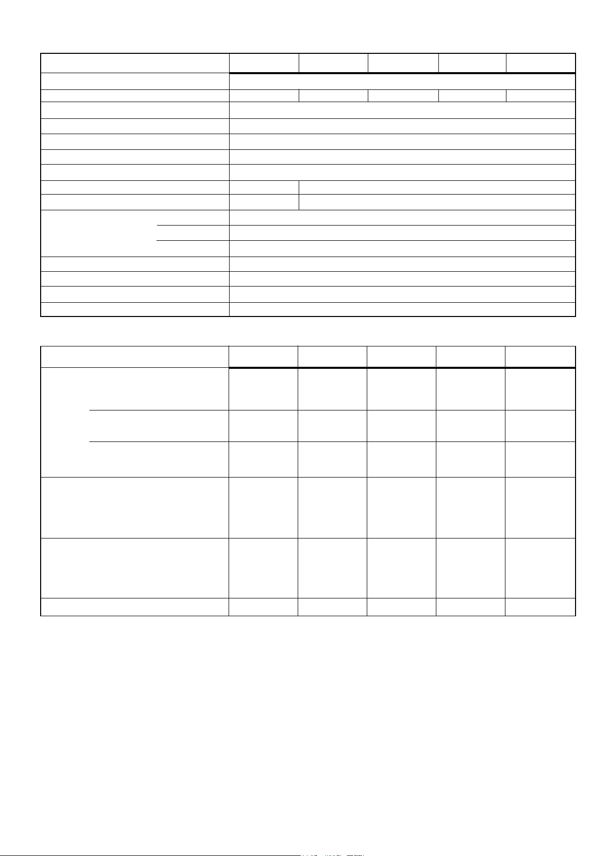
Table 1 - General Data
Boiler Size 40 FF 50 FF 60 FF 70 FF 80 FF
Gas Supply Connection in. BSP Rc 1/2 (1/2)
Number of Boiler Sections 2 3 3 3 3
Flow and Return Connections Rc 1 (1" BSP)
MAXIMUM Static Water Head m (ft.) 30.5 (100) (3 bar)
MINIMUM Static Water Head m (ft.) 1.0 (3.3)
Electrical Supply (Power Consumption) 230 V ~50 Hz (100 W)
Fuse Rating External: 3 A Internal: 1A to BS4265
Water Content litre (gal.) 5.0 (1.1) 7.4 (1.6)
Dry Weight kg. (lb.) 68 (150) 90 (198)
Boiler Size Height mm (in.) 850 (33.5)
Width mm (in.) 440 (17.4)
Depth mm (in.) 533 (21.0)
Gas Type Natural 2 H
Gas Supply Pressure 20 mb
Flue duct diameter mm (in.) 100 (4.0)
Flue duct length (max) m (ft) 3 (9.8)
Table 2 - Performance Data
Boiler Size 40 FF 50 FF 60 FF 70 FF 80 FF
Boiler Input
MINIMUM kW (Btu/h) 11.1 (37 700) 14.7 (50 300) 18.4 (62 900) 22.1 (75 500) 25.8 (88 100)
Gas Consumption l/s (ft.3/h) 0.29 (36.4) 0.38 (48.5) 0.48 (60.6) 0.57 (72.7) 0.67 (84.8)
MID kW (Btu/h) 12.9 (43 900) 16.5 (56 500) 20.2 (69 000) 23.9 (81 600) 27.6 (94 100)
3
Gas Consumption l/s (ft.
/h) 0.33 (42.3) 0.43 (54.4) 0.52 (66.5) 0.62 (78.6) 0.71 (90.7)
MAXIMUM kW (Btu/h) 14.7 (50 000) 18.3 (62 500) 22.0 (75 000) 25.6 (87 500) 29.3 (100 000)
3
Gas Consumption l/s (ft.
/h) 0.38 (48.2) 0.47 (60.2) 0.57 (72.3) 0.66 (84.3) 0.76 (96.3)
Boiler Output to Water
MINIMUM kW (Btu/h) 8.8 (30 000) 11.7 (40 000) 14.7 (50 000) 17.6 (60 000) 20.5 (70 000)
MID kW (Btu/h) 10.3 (35 000) 13.2 (45 000) 16.1 (55 000) 19.1 (65 000) 22.0 (75 000)
MAXIMUM kW (Btu/h) 11.7 (40 000) 14.7 (50 000) 17.6 (60 000) 20.5 (70 000) 23.4 (80 000)
Burner Setting Pressure (hot)
MINIMUM mbar (in w.g.) 5.8 (2.3) 7.4 (3.0) 8.5 (3.4) 8.0 (3.2) 10.7 (4.3)
MID mbar (in w.g.) 7.8 (3.1) 9.4 (3.8) 10.5 (4.2) 9.3 (3.7) 12.2 (4.9)
MAXIMUM mbar (in w.g.) 10.4 (4.2) 11.6 (4.7) 12.6 (5.1) 10.9 (4.4) 14.0 (5.6)
Seasonal Efficiency (SEDBUK)* [76.8]% [76.3]% [77.1]% [77.3]% [79.0]%
* The value is used in the UK Government's Standard Assessment Procedure (SAP) for energy rating of dwellings.
The test data from which it has been calculated have been certified by BG plc 0087.
Note.
Gas consumption is calculated using a calorific value of 38.7
3
(1038 Btu/ft3) gross or 34.9 MJ/m3 (935 Btu/ft3) nett. To
MJ/m
obtain the gas consumption at a different calorific value:-
a. For l/s - divide the gross heat input (kW) by the gross C.V.
of the gas (MJ/m3)
b. For ft3/h - divide the gross heat input (Btu/h) by the gross
C.V. of the gas (Btu/ft3)
c. The appliance is preset at the factory to the highest
nominal rating.
Mexico Super 40 FF - 80 FF - Installation
Key to symbols
GB = United Kingdom IE = Ireland (Countries of destination)
PMS = Maximum operating pressure of water
= A room sealed appliance designed for connection via ducts
C
12
to a horizontal terminal, which admits fresh air to the burner
and discharges the products of combustion to the outside
through orifices which, in this case, are concentric. The
fan is down stream of the combustion chamber.
= An appliance designed for use on 2nd Family gas,
I
2H
Group H only.
3
Page 4

GENERAL
CONTENTS
Air Supply. ..................................................................... 7
Boiler Assembly - Exploded view ............................... 9
Boiler Clearances ......................................................... 6
Burner Assembly - Exploded view ........................... 43
Electrical Connections ............................................... 24
Electrical Diagram ...................................................... 24
Electrical Supply ........................................................... 8
Extension Ducts - Fitting ........................................... 21
Fault Finding ............................................................... 38
Flue Fitting ............................................................. 12-21
Flue Installation ............................................................ 7
Mexico Super FF
Mexico Super 40 FF G.C. No. 41 349 78
Mexico Super 50 FF G.C. No. 41 349 79
Mexico Super 60 FF G.C. No. 41 349 80
Mexico Super 70 FF G.C. No. 41 349 81
Mexico Super 80 FF G.C. No. 41 349 82
Natural Gas only Appliance type: C
Certified - P.I. No. 87 AU 83
Destination Countries: GB & IE.
INTRODUCTION
Mexico Super FF above range is of floor standing, fanned
flue gas boilers. They are range-rated to provide central
heating outputs of 8.8 kW (30,000 Btu/h) to 23.4 kW (80,000
Btu/h).
The boiler has a cast iron heat exchanger and is
supplied fully assembled, complete with a white
enamelled mild steel casing.
12
Gas Safety Regulations ............................................... 5
Gas Supply .................................................................... 7
Initial Lighting ............................................................. 28
Installation ..................................................................... 9
Mandatory Requirements ............................................ 5
Pump ............................................................................ 23
Servicing ...................................................................... 30
Short List of Parts ...................................................... 39
System Diagrams (Electrical) .................................... 26
Terminal Guards. .......................................................... 7
Water Connections .............................................. 5 & 22
Water Systems ............................................................ 23
Water Treatment ............................................................ 8
A door at the top of the casing front panel hinges down,
revealing the boiler thermostat control (and programmer,
if fitted).
The boilers are suitable, as standard, for connection to
open-vented systems ONLY - an overheat thermostat kit
is available to allow the boiler to be used on sealed water
systems.
The systems may be:
z pumped or gravity circulating indirect DHW only
z pumped central heating only
z pumped central heating combined with either a
pumped or gravity circulating indirect DHW circuit.
OPTIONAL EXTRA KITS
Extension Duct Kit Pack D.
Programmer Kit Fits neatly within the casing. Separate
fitting instructions are included with this
kit.
Overheat is available to allow the boiler to be used
Thermostat Kit on sealed water systems.
Flue Elbow Kits 90 degree pack
45 degree pack
NOTE TO THE INSTALLER:
LEAVE THESE
INSTRUCTIONS ADJACENT TO THE GAS METER.
ALSO COMPLETE THE BENCHMARK LOG BOOK
AND GIVE THIS TO THE CUSTOMER.
4
Mexico Super 40 FF - 80 FF - Installation
Page 5

GENERAL
GAS SAFETY
Gas Safety (Installation and Use) Regulations, 1994,
Amendments 1996 or the rules in force.
It is law that all gas appliances are installed by a CORGI
registered installer (identified by
above regulations. Failure to install appliances correctly could
lead to prosecution. It is in your own interest, and that of safety,
to ensure the law is complied with.
The installation of the boiler MUST also be in accordance with
the latest I.E.E (BS 7671) Wiring Regulations, local building
regulations, bylaws of the local water authority, the Building
Regulations and Building Standards (Scotland) and any
relevant requirements of the local authority.
Detailed recommendations are contained in the following
British Standard Codes of Practice:
BS. 6891 Low pressure installation pipes.
BS. 6798 Installation of gas fired hot water boilers of rated
input not exceeding 60 kW.
BS. 5449:1 Forced circulation hot water systems (small bore
and microbore domestic central heating
systems).
BS. 5546 Installation of gas hot water supplies for domestic
purposes (2nd Family Gases).
BS. 5440: 1 Flues for gas appliances of rated input not
exceeding 60 kW.
BS. 5440: 2 Ventilation for gas appliances of rated input not
exceeding 60 kW.
BS 7593 Treatment of water in Domestic Hot Water
Central Heating Systems.
) in accordance with the
Health and Safety Document No. 635.
The Electricity at Work Regulations, 1989.
Manufacturer’s notes must NOT be taken in any way as
overriding statutory obligations.
IMPORTANT. These appliances are certificated by the British
Standards Institution for safety and performance. It is
important, therefore, that no external control devices, e.g. flue
dampers, economisers etc., are directly connected to these
appliances unless covered by these Installation and Servicing
Instructions or otherwise recommended by Caradon Plumbing
Limited in writing. If in doubt please enquire.
Any direct connection of a control device not approved by
Caradon Plumbing Limited could invalidate the BSI
Certification and the normal appliance warranty. It could also
infringe the Gas Safety Regulations and the above regulations
or other statutory requirements.
LOCATION OF BOILER
The boiler must be installed on a flat and level floor, capable of
adequately supporting the weight of the boiler and any ancillary
equipment.
The boiler may be fitted on a combustible floor.
Insulation is not necessary, unless required by the local
authority.
The boiler must not be fitted outside.
Timber Framed Buildings
If the boiler is to be fitted in a timber framed building it should
be fitted in accordance with the Institute of Gas Engineers
document IGE/UP/7 : 1998.
1
BOILER WATER CONNECTIONS
1. This appliance is NOT suitable for use in a
direct hot water system.
2. If the boiler is to be used on a sealed system,
an Overheat Thermostat Kit is available and
must be installed in accordance with the
instructions supplied with the kit.
Boiler Dimension A
40 FF 152mm (6")
50 FF / 60 FF 226mm (8
70 FF / 80 FF 226mm (8 7/8")
7/8")
Mexico Super 40 FF - 80 FF - Installation
5
Page 6

GENERAL
Bathrooms
The boiler may be installed in any room or internal space,
although particular attention is drawn to the requirements of the
current I.E.E. (BS 7671) Wiring Regulations and, in Scotland,
the electrical provisions of the building regulations applicable in
Scotland with respect to the installation of the boiler in a room
or internal space containing a bath or shower.
Where a room-sealed appliance is installed in a room
containing a bath or shower then the appliance and any
electrical switch or appliance control utilising mains electricity
should be so situated that it cannot be touched by a person
using the bath or shower.
Where installation will be in an unusual location, special
procedures may be necessary and BS.6798 gives detailed
guidance on this aspect.
Compartment Installations
A compartment used to enclose the boiler MUST be designed
and constructed specially for this purpose.
An existing cupboard or compartment may be used, providing it
2
FLOOR MOUNTING AND BOILER CLEARANCES
Flammable materials must not be placed in close proximity to
the appliance. Materials giving off flammable vapours must
not be stored in the same room as the appliance.
Floor mounting
1. The floor must be flat, level and of suitable load bearing
capacity.
2. The back of the boiler may be fitted up to the wall.
Boiler clearances
The minimum overall dimensions of the space in which the
boiler is to operate and to facilitate servicing are as shown in
the Table.
is modified for the purpose.
In both cases details of essential features of cupboards/
compartment design, including airing cupboard installation, are
to conform to the following:
zz
z BS. 6798.
zz
zz
z The position selected for installation MUST allow
zz
adequate space for servicing in front of the boiler
and for air circulation around the boiler.
Side clearance is only necessary for installation. The
amount of side clearance will depend upon the type of
connection used.
z This position MUST also permit the provision of a
satisfactory flue termination.
z For the minimum clearances required for safety, and
subsequent service, see Frame 2.
Additional space will be required for installation, depending
upon site conditions.
IMPORTANT.
In order to facilitate gas connection, a clearance of at least
100 mm (4") must be available at either the left hand side or
the right hand side DURING installation. Refer to Frame 30.
In addition a MINIMUM clearance of 533 mm (21") MUST
be available at the front of the boiler, for servicing.
Boiler Flue Overall Space dimension Minimum Side Clearance 'A'
Model Length Depth Height Width Width Rear Flue Side/Top Flue
Rear Flue Side/Top
40 FF, 50 FF, 114 to 533 mm 870 mm 460 mm 510 mm 10 mm 35 mm
60 FF, 70 FF 600 mm (21") (34
80 FF
40 FF, 50 FF, 600 to 533 mm 870 mm 510 mm 510 mm 35 mm 35 mm
60 FF, 70 FF 3000mm (21") (34
80 FF (23
(4 1/2"-23 5/8")
5/8"-118")
6
1/4") (18 1/8") (20 1/8")(3/8") (1 3/8")
1/4") (20 1/8") (20 1/8")(1 3/8") (1 3/8")
Mexico Super 40 FF - 80 FF - Installation
Page 7

GENERAL
GAS SUPPLY
The local gas supplier should be consulted, at the installation
planning stage, in order to establish the availability of an
adequate supply of gas. An existing service pipe must NOT be
used without prior consultation with the local gas supplier.
The boiler is to be installed only on a gas supply with a
governed meter.
A gas meter can only be connected by the local gas supplier or
by a local regional contractor.
Check that the appliance is suitable for the proposed gas
supply. An existing meter should be checked, preferably by the
gas supplier, to ensure that the meter is adequate to deal with
the rate of gas supply required. A minimum gas pressure of
20 mbar MUST be available at the boiler inlet, with the boiler
operating.
Installation pipes MUST be fitted in accordance with BS. 6891.
Pipework from the meter to the boiler MUST be of an adequate
size.
The complete installation MUST be tested for gas soundness
and purged as described in the above code.
FLUE INSTALLATION
Some pluming may occur at the termination so terminal
positions where this could cause a nuisance should be
avoided.
The flue must be installed in accordance with the
recommendations of BS. 5440:1.
The following notes are intended for general guidance:-
1. The boiler MUST be installed so that the terminal is
exposed to external air.
2. It is important that the position of the terminal allows the
free passage of air across it at all times.
3. Minimum acceptable spacing from the terminal to
obstructions and ventilation openings are specified in
Table 3.
4. Where the lowest part of the terminal is fitted less than 2m
(6'6") above a balcony, above ground or above a flat roof to
which people have access then the terminal MUST be
protected by a purpose designed guard. The minimum
Table 3 - Balanced flue terminal position
Terminal Position
1. Directly below or alongside an
opening window, air vent or other
ventilation opening 300 mm (12")
2. Below guttering, drain pipes or soil
pipes 25 mm ( 1")
3. Below eaves 25 mm ( 1")
4. Below balconies or a car port roof 25 mm ( 1")
5. From vertical drain pipes or soil pipes 25 mm ( 1")
6. From internal or external corners 25 mm ( 1")
7. Above adjacent ground, roof or
balcony level 300 mm (12")
8. From a surface facing the terminal 600 mm (24")
9. From a terminal facing a terminal 1200 mm (48")
10. From an opening in a car port
(e.g. door or window) into dwelling 1200 mm (48")
11. Vertically from a terminal on the
same wall 1500 mm (60")
12. Horizontally from a terminal on the wall 300 mm (12")
Minimum Spacing
spacing in Table 3, Nos. 2,3, 4, 5 and 6 would be 75mm in
order to allow a terminal guard to be fitted.
Terminals guards are available from boiler suppliers - ask
for Tower Flue Guard, Model K1. In case of difficulty seek
advice from:
Tower Flue Components Ltd.,
Vale Rise, Tonbridge, Kent TN9 1TB (Model K1)
Telephone No. 01732 351 555
Ensure that the guard is fitted centrally.
5. Where the terminal is fitted within 1000mm (39
plastic or painted gutter or 500mm (19 1/2") of painted
eaves then an aluminium shield at least 1000mm (39 1/2")
long should be fitted to the underside of the gutter or
painted surface.
6. The air inlet/products outlet duct and the terminal of the
boiler MUST NOT be closer than 25mm (1") to
combustible material. Detailed recommendations on the
protection of combustible material are given in BS.5440:
1990.
7. Where it is essential that the terminal wall plate is fitted, i.e.
wall thicknesses over 600mm (23
cut hole, the minimum spacing in Table 3 Nos. 2,3, 4, 5 and
6 would be 60mm (2 1/2") in order to allow the terminal wall
plate to be fitted.
IMPORTANT.
It is absolutely ESSENTIAL to ensure, in practice, that
products of combustion discharging from the terminal cannot
re-enter the building or any other adjacent building through
ventilators, windows, doors, other sources of natural air
infiltration or forced ventilation/air conditioning. If this should
occur, the appliance MUST be turned OFF, labelled 'unsafe'
and corrective action taken.
1/2") or with an inaccurately
1/2") of a
TERMINAL
The terminal assembly can be adapted to accommodate
various wall thicknesses. Refer to Frames 7 and 27.
AIR SUPPLY
Detailed recommendations for air supply are given in
BS.5440:2. The following notes are for general guidance:
1. It is NOT necessary to have a purpose provided air vent in
the room or internal space in which the boiler is installed.
2. If the boiler is to be installed in a cupboard or
compartment, permanent air vents are required (for
cooling purposes) in the cupboard/compartment, at both
high and low levels. The air vents must either
communicate with room/internal space, or be direct to
outside air. The minimum effective areas of the
permanent air vents, required in the cupboard/
compartment, are specified as follows and are related to
maximum rated heat input.
3. Both air vents MUST communicate with the same room or
internal space or MUST be on the same wall to outside
air.
4. In siting the air vents care must be taken to avoid the
freezing of pipework.
Table 4 - High and low vent areas
Boiler Air from room/internal Air direct from
space cm2 (in.2) outside cm2 (in.2)
High level Low level High level Low level
40 FF 143 (23) 143 (23) 72 (12) 72 (12)
50 FF 173 (27) 173 (27) 87 (14) 87 (14)
60 FF 208 (33) 208 (33) 104 (17) 104 (17)
70 FF 245 (38) 245 (38) 123 (19) 123 (19)
80 FF 282 (44) 282 (44) 141 (22) 141 (22)
Mexico Super 40 FF - 80 FF - Installation
7
Page 8

GENERAL
WATER CIRCULATION SYSTEM
The boiler must NOT be used for direct hot water supply or for
sealed systems. The boiler is suitable for connection to pumped
open vent central heating systems, pumped central heating
combined with pumped or gravity indirect domestic hot water
supply systems.
The boiler is NOT suitable for gravity heating systems. The
hydraulic resistances of the boilers at maximum output with 11
O
C (20 OF) temperature differentials are shown in the graph below.
The central heating system should be in accordance with
BS. 6798 and, in addition, for smallbore and microbore systems,
BS. 5449:1.
The domestic hot water system, if applicable, should be in
accordance with the relevant recommendations of BS. 5546.
Copper tubing to BS. 2871:1 is recommended for water carrying
pipework.
The hot water storage cylinder MUST be of the indirect type and
should preferably be manufactured of copper.
Single feed, indirect cylinders are not recommended and MUST
NOT be used on sealed systems.
The hot water cylinder and ancillary pipework not forming part of
the useful heating surface should be lagged to prevent heat loss
and any possible freezing - particularly where pipes run through
roof spaces and ventilated underfloor spaces.
IMPORTANT.
The boiler must be vented. If venting cannot be done via a flow
connection a separate vent MUST be fitted by the installer.
Draining taps MUST be located in accessible positions, which
permit the draining of the whole system - including the boiler and
hot water storage vessel. They should be at least
size and be in accordance with BS. 2879.
If required, a drain tap (not supplied) may be fitted to an unused
bottom (1" BSP) tapping on the front of the boiler.
Water Flow Rate and Pressure Loss
1/2" BSP nominal
WATER TREATMENT
The Mexico Super FF incorporates a cast iron heat exchanger.
As part of the installation the central heating system should be
thoroughly flushed with appropriate water treatment in order to
comply with BS7593:1992
Caradon Plumbing Limited recommend the use of Fernox or
Betz Dearborn water treatment products which must be used in
accordance with the manufacturers instructions. For further
information contact :-
Fernox Manufacturing. Co. Ltd., Tandem House, Marlowe
Way, Croydon, Surrey CRO 4XS, tel 0870 5601 5000
or
Betz Dearborn Ltd., Widnes, Cheshire, tel. 0151 424 5351
IMPORTANT.
ANY OTHER TREATMENT FOR THIS PRODUCT WILL
RENDER THE GUARANTEE OF CARADON PLUMBING
LIMITED INVALID.
Notes.
1. If an inhibitor is used, and in hard water areas where
treatment to prevent lime deposits is necessary, it is most
important that the water treatment MUST be maintained at
the correct concentrations recommended by the treatment
manufacturer.
2. Artificially softened water must not be used in the system,
under any circumstances.
THERMOSTATIC RADIATOR VALVES
Caradon Plumbing Limited recommend that heating systems
utilising full thermostatic radiator valve control of temperature in
individual rooms should also be fitted with a room thermostat
controlling the temperature in a space served by radiators not
fitted with such a valve, as stated in BS. 5449.
When thermostatic radiator valves are used, the space heating
temperature control over a living / dining area or hallway having
a heating requirement of at least 10% of the boiler heat output
should be achieved using a room thermostat, whilst other rooms
are individually controlled by thermostatic radiator valves.
However, if the system employs thermostatic radiator valves on
all radiators or two port valves without end switches then a bypass
must be fitted in order to ensure a flow of water should all the
valves be in the closed position.
ELECTRICAL SUPPLY
WARNING. The appliance MUST be efficiently earthed.
Wiring external to the appliance MUST be in accordance with
the current I.E.E. (BS 7671) Wiring Regulations and any local
regulations which apply.
The boiler is supplied for 230 V ~ 50 Hz single phase. The fuse
rating is 3A.
Connection must be made in a way that allows complete isolation
of the electrical supply - such as a double pole switch, having a
1/8") contact separation in both poles, or a plug and socket
3mm (
serving only the boiler and system controls.
The means of isolation must be accessible to the user after
installation.
Dotted lines indicate flow rates equivalent to a
temperature rise of 11 OC (20 OF)
8
For bathroom installations the point of connection to the mains
must be situated outside the bathroom.
Mexico Super 40 FF - 80 FF - Installation
Page 9
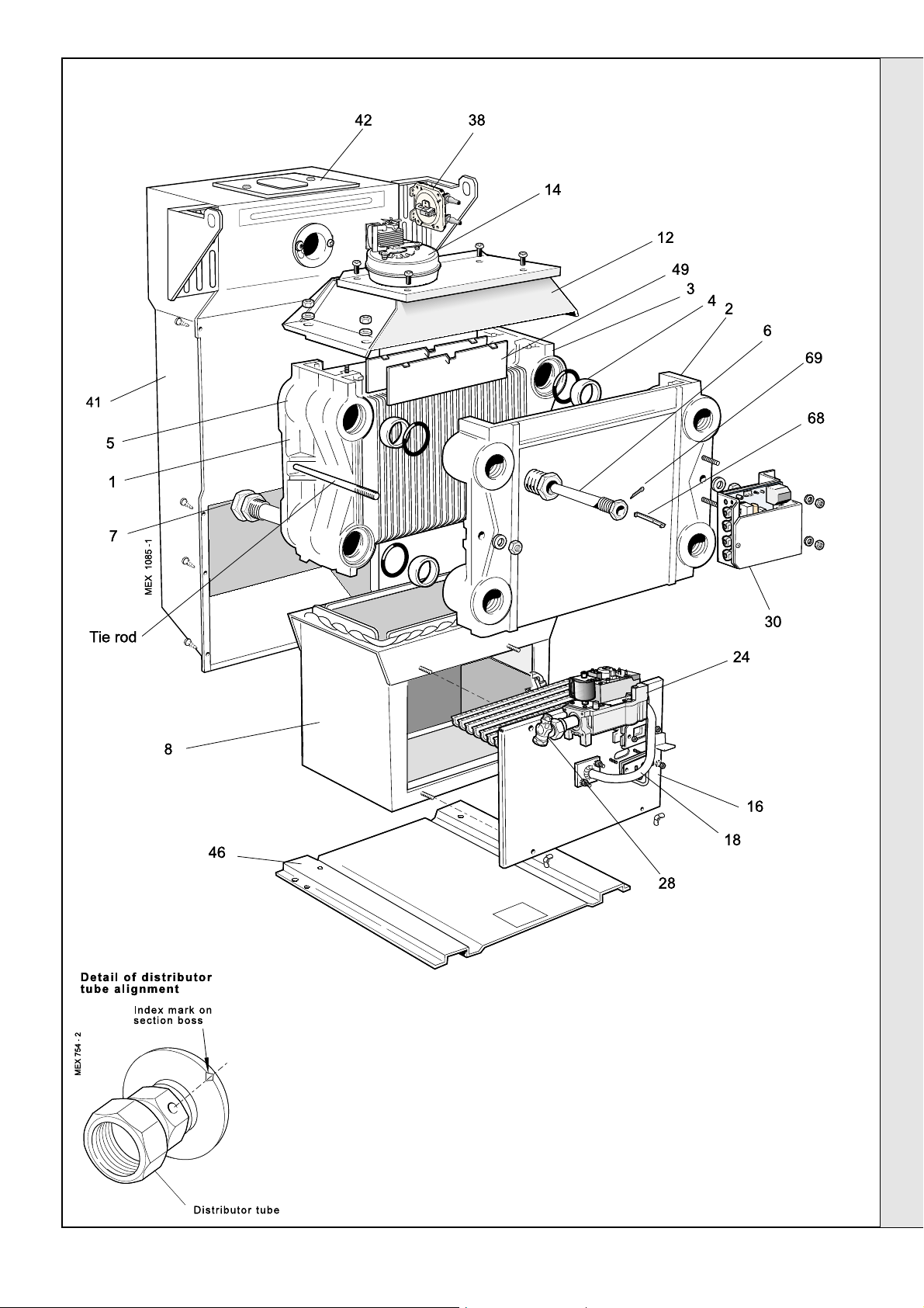
3
BOILER ASSEMBLY - Exploded View
Mexico Super FF with casing removed.
INSTALLATION
INSTALLATION
LEGEND
1. Heat exchanger assembly.
2. Front section.
3. Centre section.
4. Section alignment rings and 'O' rings.
5. Back section.
6. Thermostat pocket.
7. Distributor tube.
8. Combustion chamber.
12. Collector hood.
14. Fan assembly.
16. Front plate assy.
Mexico Super 40 FF - 80 FF - Installation
18. Burner manifold.
28. Gas cock.
30. PCB assembly.
38. Pressure switch.
41. Turret assembly.
42. Turret access cover assy.
46. Boiler base plate.
47. Baseplate heat shield.
49. Flue baffle.
68. Thermostat phial retaining clip
69. Phial split pin.
9
Page 10

INSTALLATION
4
UNPACKING
The boiler is supplied fully assembled in Pack A,
together with a standard flue assembly for lengths
up to 600mm (23 1/2") rear or side flue outlet in
Pack B.
Unpack and check the contents.
PACK A CONTENTS
z complete boiler assembly
INSTALLATION
z User's Instructions
z these Installation and Servicing Instructions
z the Hardware Pack (listed separately below)
z Template
FLUE PACK. Pack B Contents
z Duct cutting support, 2 off (cardboard )
z Terminal wall plate, 1 off.
z Terminal grille assy., 1 off.
z Polyurethane foam seal 400 lg., 1 off.
z No. 8 x 8 lg. Pozi pan hd. screws, 3 off.
complete boiler assembly
BOILER HARDWARE PACK
z 1" BSP plugs - 5 off
z 1" x
z Distributor tube
z Thermostat pocket -1 off
z Thermostat clip (RS 3/50, RS 3/60,
z Thermostat retaining pin - 1 off
z Output setting label -1 off
1/2" BSP reducing bush - 1 off
RS 3/70 & RS 3/80 only) - 1 off
FLUE HARDWARE PACK
z Flue extension tube (rear)
z Flue extension tube (side)
z Flue extension tube (top)
z Elbow
z Sealing ring
5
BOILER CASING REMOVAL
To install the boiler the casing MUST be removed.
1. Undo the 2 screws and lift off the lower front panel.
2. Remove 2 screws and lift off the grille assembly.
3. Disconnect the in-line electrical connector between
the control box and the PCB box.
4. Remove the thermostat phial from the pocket as
shown in Frame 6.
5. Remove the 2 screws securing the control panel and
pull down to release the tabs from under the top
panel.
z M5 wing nuts - 3 off
z Side outlet plate
6. Remove the 2 screws securing the top panel to the
side.
10
Mexico Super 40 FF - 80 FF - Installation
Page 11

INSTALLATION
6
BOILER CASING REMOVAL - continued
7. Draw the top panel forward and lift it off the boiler.
8. Remove the 2 screws securing the LH side panel to the
turret front panel and baseplate.
9. Pull the panel forward, disengaging from the collector hood
tab, lifting it clear of the locating peg and remove.
10. Repeat steps 8 and 9 to remove the RH panel.
INSTALLATION
11. The boiler is held to the packaging base by 4 M6
hex head screws. Remove the front screws,
slacken the rear screws and remove the boiler
from the packaging base.
7
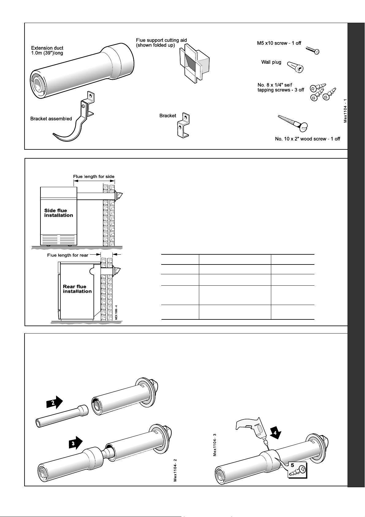
DETERMINING THE FLUE LENGTH
It is MOST IMPORTANT that the boiler is installed in a vertical position.
WARNING.
For top outlet installation the flue terminal
MUST always be in the horizontal position.
Top outlet flue length
= A + B + Elbow allowance
o
Elbow = 1m
90
o
Elbow = 0.7m
45
FLUE KITS
Pack B: supplied as standard.
Pack D: optional extension kit for
side flue or rear flue outlet. Refer
to 'Flue Extension Ducts'
1. A maximum of 3 extension
ducts (plus the standard flue
duct) may be used together.
2. Flue extensions of greater
than 1m (39") should be
supported with the bracket
provided.
Mexico Super 40 FF - 80 FF - Installation
Flue length
Up to 600 B, 1 off 152 227
600 to 1550 B, 1 off + D, 1 off 152227+152132
1550 to 2500 B, 1 off + D, 2 off 152 227+
2500 to 3000 B, 1 off + D, 3 off 152 227+
mm
Pack Requirement Product No.
152132, 2 off
152132, 3 off
11
Page 12

INSTALLATION
8
PREPARING THE BOILER
Table 7 - Fully Pumped Systems
Connections - as viewed at front Thermostat Position
Back Section Front Section
Flow Return Top
LH LH LH
LH RH LH
RH RH RH
RH LH RH
Table 8 - Gravity Domestic Hot Water
and Pumped Central Heating
Notes.
z Before placing the boiler in the selected position any
gas and water connections at the rear of the boiler
should be prepared, due to the possible lack of access.
z The pump may be fitted to the FLOW or the RETURN.
1. Screw the distributor tube (supplied with a 1" BSP x
28mm copper adaptor) into the selected heating return
tapping, using an appropriate jointing material.
IMPORTANT. It is IMPERATIVE that the index mark on
the distributor tube bush is in alignment with the mark on
the section boss, as shown in Frame 3.
DO NOT disturb it when connecting subsequent
pipework.
Fully pumped systems using more than 1 pump, serving
separate zones, must have a common return connection
to the distributor tube.
Connections - as viewed at front Thermostat Position
Back Section Front Section
CH DHW
Flow Return Flow Return Top
LH LH RH RH LH
LH RH RH LH LH
RH RH LH LH RH
RH LH LH RH RH
9
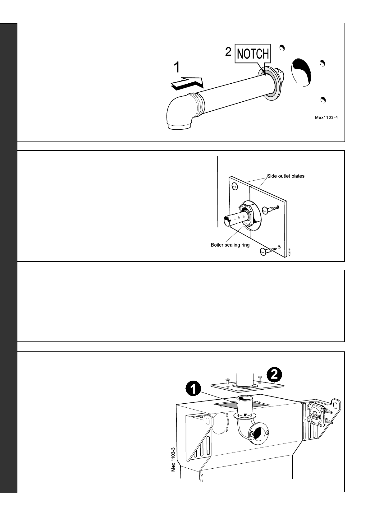
REAR FLUE ASSEMBLY - Exploded view
1. The boiler turret assembly is factory built for rear flue
installation.
2. Remove the turret access cover.
3. Fit the long flue extension tube (with ring) to the flue
connector, rotate in the bayonet slot and secure with the M4
screws.
2. Select the desired pumped flow tapping.
3. Screw the supplied boiler thermostat pocket into the
appropriate front section tapping, using an approved
jointing material. Refer to Tables 7 and 8.
4. Connect pipe fittings to the rear tappings and plug any
unused tappings.
Note. If using iron elbows fit a short straight connector into
the boiler tapping first, to clear the casing.
LEGEND
1. Terminal.
2. Weather seal.
3. Flue assembly.
4. Boiler sealing ring.
5. Flue extension tube
(long, with ring).
6. Sealing plate.
7. Flue connector.
8. Turret access cover.
REAR FLUE OUTLET
12
Mexico Super 40 FF - 80 FF - Installation
Page 13

10
PREPARING THE WALL
1. Tape the template into the selected
position.
2. Mark onto the wall the position of the
flue duct hole.
IMPORTANT. Ensure that, during the
cutting operation, masonry falling outside
of the building does not cause damage or
personal injury.
3. Cut the flue hole, preferably with a
125mm (5") core boring tool, ensuring
that the hole is square to the wall. If
the hole has been quite accurately cut
with a drill then making good the wall
faces is not essential as seals are
provided at both ends of the flue.
However, both wall faces immediately
around the cut hole should be flat;
make good if necessary. For less
accurate holes make good to
approximately 125mm (5") diameter at
the 2 wall faces.
4. Remove the template from the wall.
INSTALLATION
Note.
If the terminal is to be
sited within 25-40mm
of a corner or vertical
pipe (refer to Table 3)
then the hole MUST
be accurately cut and
the rubber weather
seal trimmed around
the groove provided.
The terminal wall plate
need not be fitted.
11
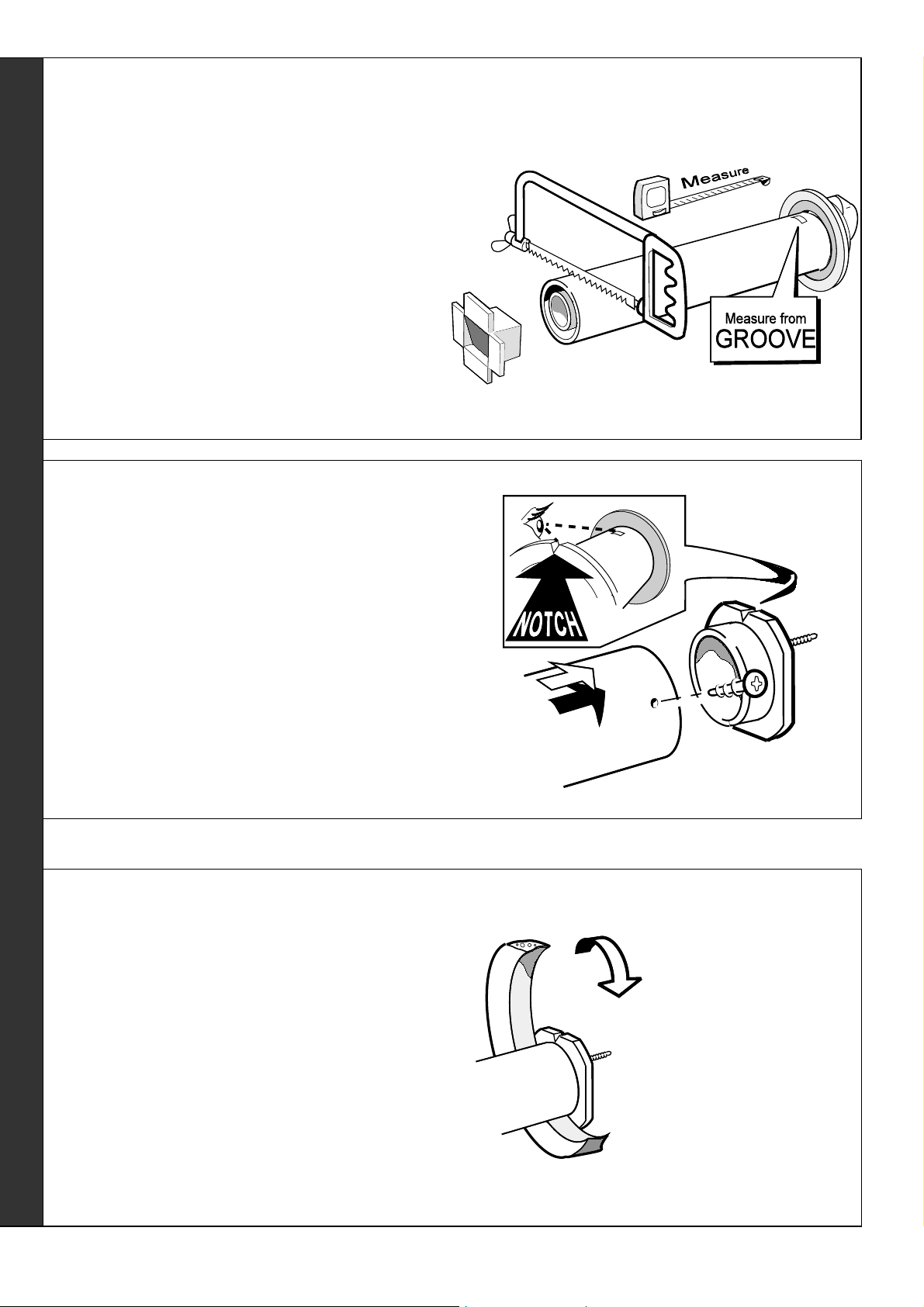
CUTTING THE FLUE - wall thicknesses of 114 to 600mm
1. Measure and note the wall thickness X.
2. Mark the wall thickness onto the flue.
3. To ensure the tube is cut square, mark
the flue all the way round.
4. Cut to length X, using the cardboard ring
for support.
5. Remove cardboard ring and remove any
burrs.
12
FITTING THE BOILER SEALING RING TO THE FLUE
1. Fit the boiler sealing ring inside the outer flue duct. Ensure
the boiler sealing ring is fully engaged.
Ensure the notch aligns with the groove on the outer flue
duct. This ensures correct alignment of the flue terminal.
2. Drill 3 holes 3.2mm (
and boiler sealing ring.
1/8") dia. through the outer flue duct
Do NOT drill the inner flue
duct.
3. Insert the self-tapping screws, provided, in order to fix the
boiler sealing ring in position.
4. If the boiler is located with the rear against the wall, stick
the self-adhesive foam strip, provided in the hardware
pack, onto the flue immediately behind the boiler sealing
ring, otherwise refer to Frame 13.
REAR FLUE OUTLET
Mexico Super 40 FF - 80 FF - Installation
13
Page 14

13
FITTING THE FOAM SEAL
INSTALLATION
14
FITTING THE FLUE ASSEMBLY
1. To determine the position for the foam
seal measure the wall thickness and
mark it onto the flue, measuring from the
groove near the terminal.
2. Wrap the self-adhesive foam strip round
the flue, ensuring that the foam is on the
terminal side of the line. This seals the
gap between the flue and the wall.
A. Inside fitting.
If the flue assembly cannot be fitted from the outside, proceed as
follows:
1. Insert the flue assembly through the hole far enough to allow the
rubber seal to unfold completely and form an adequate seal on
the outside wall.
2. Ensure the notch is at the top. This will aid the location of the
studs into the boiler back panel.
3. Proceed to Frame 15, item B.
B. Outside fitting.
Proceed to Frame 15, item A.
15
LOCATING THE BOILER
A. If the flue assembly can be fitted from the outside,
proceed as follows:
1. Move the boiler into position ensuring that the flue
outlet is in line with the wall opening.
2. Insert the flue assembly ensuring that the flue slides
into the flue extension and the 3 sealing ring studs
locate into the boiler.
16
CONNECTING THE FLUE TO THE BOILER
1. Secure the flue to the boiler using the
three M5 wing nuts provided.
Note.
The sealing plate studs will locate in the
back panel one way only. This will ensure
that the terminal is correctly aligned.
B. If the flue assembly has been fitted from the inside
proceed as follows:
1. Move the boiler into position ensuring that the
flue slides into the flue extension tube and the 3
sealing ring studs locate into the boiler back panel.
REAR FLUE OUTLET
14
Mexico Super 40 FF - 80 FF - Installation
Page 15

17
SIDE FLUE ASSEMBLY - Exploded view
For wall thickness 114mm to 600mm
INSTALLATION
1. The boiler turret assembly is factory built for rear flue
installation.
2. Remove the turret access cover.
3. Remove the sealing plate from the appropriate side to
be used and refit in the rear outlet.
LEGEND
1. Terminal.
2. Weather seal.
3. Flue assembly.
4. Boiler sealing ring.
5. Flue extension tube (medium with ring).
4. An optional flue duct extension kit is required for lengths
(distance from the outside wall to the relevant side of
the boiler casing) greater than 600mm (23 1/2") Refer to
Frame 7.
5. When cutting the ducts always use the cardboard
support provided.
6. Elbow.
7. Side outlet plate.
8. Flue connector.
9. Sealing plate.
10. Turret access cover.
18
PREPARING THE WALL
1. Tape the template into the selected
position.
2. Mark onto the wall the position of the
flue duct hole.
IMPORTANT. Ensure that, during the
cutting operation, masonry falling
outside of the building does not cause
damage or personal injury.
3. Cut the flue hole, preferably with a
125mm (5") core boring tool,
ensuring that the hole is square to
the wall. If the hole has been quite
accurately cut with a drill then
making good the wall faces is not
essential as seals are provided at
both ends of the flue. However, both
wall faces immediately around the
cut hole should be flat; make good if
necessary. For less accurate holes
make good to approximately
125mm (5") diameter at the 2 wall
faces.
Note. If the
terminal is to be
sited within 2540mm of a
corner or
vertical pipe
(refer to Table
3) then the hole
MUST be
accurately cut
and the rubber
weather seal
trimmed around
the groove
provided.
The terminal
wall plate need
not be fitted.
SIDE FLUE OUTLET
Mexico Super 40 FF - 80 FF - Installation
15
Page 16
INSTALLATION
19
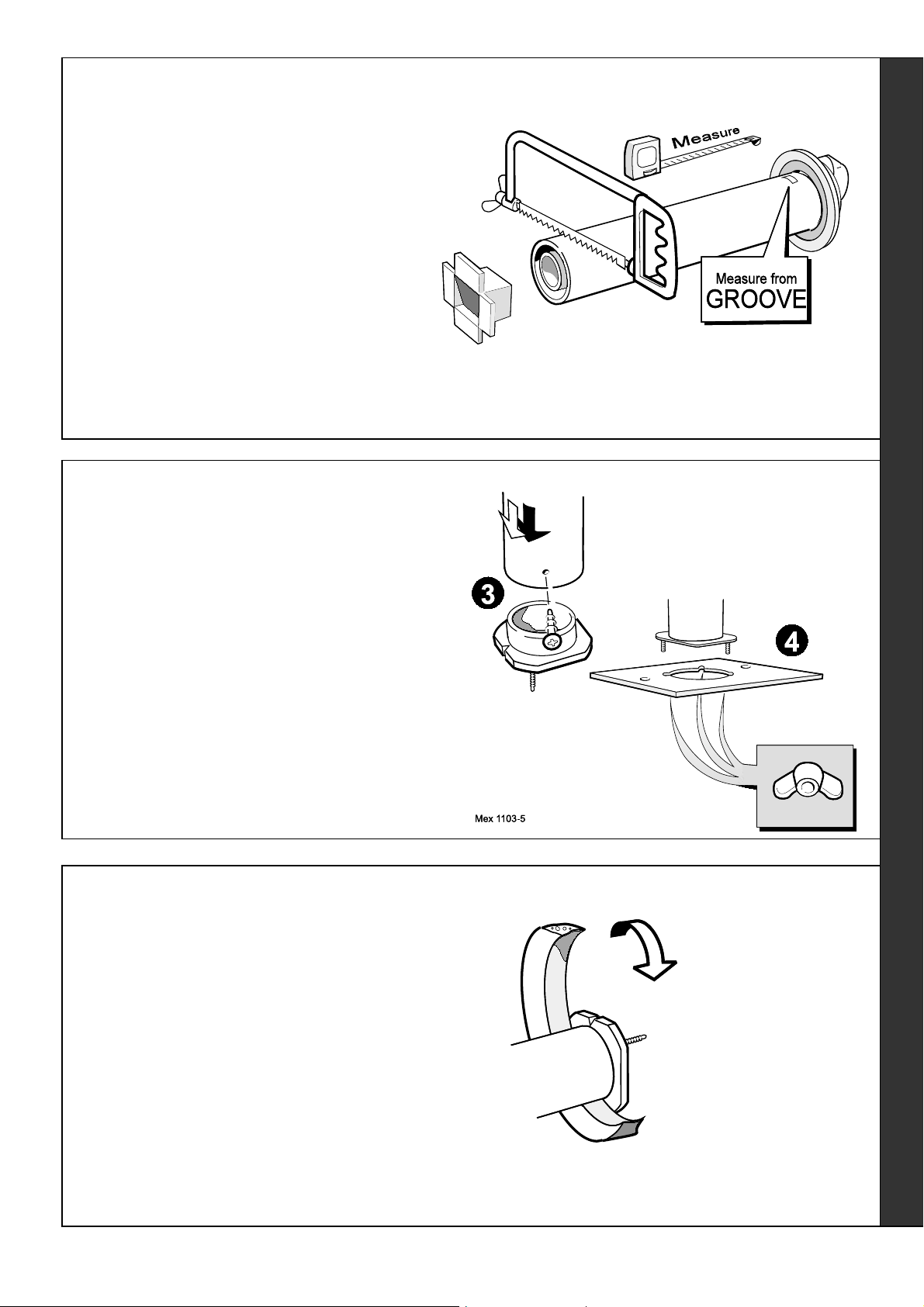
CUTTING THE FLUE - wall thicknesses of 114 to 600mm
1. Measure and note the wall thickness X.
2. Mark the wall thickness onto the flue.
3. To ensure the tube is cut square, mark the flue all the
way round.
4. Cut to length X, using the cardboard ring for support.
5. Remove cardboard ring and remove any burrs.
20
FITTING BOILER SEALING RING TO THE FLUE
1. Fit the boiler sealing ring inside the outer flue duct.
Ensure the boiler sealing ring is fully engaged.
Ensure the notch aligns with the groove on the outer flue
duct. This ensures correct alignment of the flue terminal.
2. Drill 3 holes 3.2mm (
and boiler sealing ring.
3. Insert the self tapping screws, provided, in order to fix
the boiler sealing ring in position.
21
FITTING THE FOAM SEAL
1. To determine the position for the
foam seal measure the wall
thickness and mark it onto the flue,
measuring from the groove near the
terminal.
2. Wrap the self-adhesive foam strip
round the flue, ensuring that the
foam is on the terminal side of the
line. This seals the gap between the
flue and the wall.
1/8") dia. through the outer flue duct
Do not drill the inner flue duct.
SIDE FLUE OUTLET
16
Mexico Super 40 FF - 80 FF - Installation
Page 17

INSTALLATION
22
FITTING THE FLUE ASSEMBLY
A. Inside fitting.
If the flue assembly cannot be fitted from the outside, proceed as follows:
1. Insert the flue assembly through the hole far
enough to allow the rubber seal to unfold
completely and form an adequate seal on the
outside wall.
2. Ensure the notch is at the top. This will aid the
location of the studs into the boiler back panel.
3. Proceed to Frame 25, item B.
B. Outside fitting.
Proceed to Frame 25, item A.
23
FITTING THE SIDE OUTLET PLATES
Note. If the boiler is fitted closer than 25mm to the side wall
the side outlet plate must be fitted now.
1. Split the side outlet plate into 2 down the split line.
2. Fit the 2 halves of the side outlet plate to the wall,
ensuring they are behind the boiler sealing ring.
24
LOCATING THE BOILER
A. If the flue assembly can be fitted from the outside, proceed
as follows:
1. Move the boiler into position ensuring that the flue outlet
is in line with the wall opening.
2. Insert the flue assembly ensuring that the flue slides
into the flue extension and the 3 sealing ring studs
locate into the boiler.
25
CONNECTING THE FLUE TO THE BOILER
1. Secure the flue to the boiler, using the
three M5 wing nuts provided.
2. Fit the medium length extension tube (with
ring) to the flue elbow, rotate in the bayonet
slot and secure with the M4 screw.
3. Engage the extension tube into the flue
outlet, connect the elbow to the fan outlet
and secure with the M4 screw.
Note.
The sealing plate studs will locate in the back
panel one way only. This will ensure that the
terminal is correctly aligned.
B. If the flue assembly has been fitted from the inside
proceed as follows:
1. Move the boiler into position ensuring that the flue
slides into the flue extension tube and the 3 sealing
ring studs locate into the boiler back panel.
Mexico Super 40 FF - 80 FF - Installation
SIDE FLUE OUTLET
17
Page 18

INSTALLATION
26
TOP FLUE OUTLET ASSEMBLY - Exploded view
Note.
For the number of extension ducts required see Frame 36.
1. The boiler turret assembly is factory built for rear flue
installation.
2. Remove the turret access cover.
3. Remove the sealing plate from the turret access cover and
refit in the rear outlet.
4. Fit the outlet flue elbow pointing upwards, rotate in the
bayonet slot and secure with the M4 screw.
5. Fit the short extension tube (with no ring) to the flue
elbow, rotate in the bayonet slot and secure with the M4
screw.
6. An optional flue duct extension kit is required for lengths
(distance from the outside wall to the relevant side of the
boiler casing) greater than 600mm (23 1/2") Refer to
Frame 7.
7. When cutting the ducts always use the cardboard support
provided.
LEGEND
1. Terminal.
2. Weather seal.
3. Flue assembly.
4. Boiler sealing ring.
5. Flue extension tube (short).
6. Elbow.
7. Flue connector.
8. Turret access cover.
27
PREPARING THE WALL
1. Mark onto the wall the position of the flue duct hole.
IMPORTANT. Ensure that, during the cutting operation,
masonry falling outside of the building does not cause
damage or personal injury.
2. Cut the flue hole, preferably with a 125mm (5") core
boring tool, ensuring that the hole is square to the wall.
If the hole has been quite accurately cut with a drill then
making good the wall faces is not essential as seals are
provided at both ends of the flue. However, both wall
faces immediately around the cut hole should be flat;
make good if necessary. For less accurate holes make
good to approximately 125mm (5") diameter at the two
wall faces.
TOP FLUE OUTLET
Note. If the
terminal is to be
sited within 2540mm of a
corner or
vertical pipe
(refer to Table 3)
then the hole
MUST be
accurately cut
and the rubber
weather seal
trimmed around
the groove
provided.
The terminal
wall plate need
not be fitted.
18
Mexico Super 40 FF - 80 FF - Installation
Page 19
INSTALLATION
28
CUTTING THE FLUE - wall thicknesses of 114 to 600mm
1. Measure and note the wall thickness X.
2. Mark the wall thickness onto the flue.
3. To ensure the tube is cut square, mark the flue all
the way round.
4. Cut to length X, using the cardboard ring for support.
5. Remove cardboard ring and remove any burrs.
29
FITTING BOILER SEALING RING TO THE FLUE
1. Fit the boiler sealing ring inside the appropriate length
(A) of outer flue duct (refer to Frame 7). Ensure the
boiler sealing ring is fully engaged.
2. Drill 3 holes 3.2mm (
and boiler sealing ring. Do not drill the inner flue duct.
3. Insert the self tapping screws, provided, in order to fix
the boiler sealing ring in position.
4. Fit the turret access cover to the sealing ring.
30
FITTING THE FOAM SEAL
1. To determine the position for the foam seal
measure the wall thickness and mark it onto
the flue, measuring from the groove near the
terminal.
2. Wrap the self-adhesive foam strip round the
flue, ensuring that the foam is on the terminal
side of the line. This seals the gap between
the flue and the wall.
1/8") dia. through the outer flue duct
Mexico Super 40 FF - 80 FF - Installation
TOP FLUE OUTLET
19
Page 20
INSTALLATION
31
FITTING THE FLUE ASSEMBLY
Inside fitting.
1. Insert the flue assembly through the hole far
enough to allow the rubber seal to unfold
completely and form an adequate seal on the
outside wall.
2. Ensure the notch is at the top.
32
FITTING THE SIDE OUTLET PLATES
Note. If the boiler is fitted closer than 25mm to the side wall
the side outlet plate must be fitted now.
1. Split the side outlet plate into 2 down the split line.
2. Fit the 2 halves of the side outlet plate to the wall,
ensuring they are behind the boiler sealing ring.
33
LOCATING THE BOILER
Position the boiler beneath the flue assembly.
34
CONNECTING THE FLUE TO THE BOILER
1. Connect the flue terminal to the boiler, using the
length (A) of flue duct previously cut and ensuring that
the inner flue locates into the short extension tube.
2. Secure the flue to the boiler using the 2 M4 x 16mm
screws previously removed.
TOP FLUE OUTLET
20
Mexico Super 40 FF - 80 FF - Installation
Page 21
35
FLUE EXTENSION DUCTS
36
FLUE EXTENSION DUCTS - continued
FLUE KITS
Pack B: supplied as standard.
Pack D: optional extension kit for side, top or rear flue outlet. Refer to Frame 35.
1. A maximum of 3 extension ducts (plus the standard flue duct) may be used
2. Flue extensions of greater than 1m (39") should be supported with the bracket
INSTALLATION
together.
provided.
Top outlet flue length = A + B + Elbow allowance
o
Elbow = 1m
90
o
Elbow = 0.7m
45
Flue length
2500 to 3000 B, 1 off + D, 3 off 152 227+
37
FITTING THE KIT
1. Remove the cardboard support aid from the flue and
place safely to one side.
mm
Up to 600 B, 1 off 152 227
600 to 1550 B, 1 off + D, 1 off 152227+152132
1550 to 2500 B, 1 off + D, 2 off 152 227+
2. Fit the inner flue extension duct onto the inner flue duct.
3. Fit the outer flue extension duct onto the outer air duct.
4. Drill 3 - 3.2mm (
5. Insert the self tapping screws provided to fix the air duct in
6. Repeat steps 1-5 if a second flue extension is required.
Pack Requirement Product No.
152132, 2 off
152132, 3 off
1/8") dia. holes through the outer air duct.
Do not drill the inner flue duct.
position.
Mexico Super 40 FF - 80 FF - Installation
TOP REAR & SIDE FLUE OUTLET
21
Page 22

38
TERMINAL WALL PLATE
This plate allows neat concealment and full compression of
the rubber seal. Its use is not essential if the flue hole and
flue ducts have been accurately cut and the outside wall
face is flat.
1. Position the terminal wall plate over the terminal.
2. Mark and drill 4 fixing holes with an 7mm (
drill.
3. Insert the 4 plastic plugs provided.
4. Secure the plate with 4 of the No.10 x 2" screws
provided.
Note. If the terminal is less than 2m (6' 6") above ground
level, an approved terminal guard should be fitted. Refer to
INSTALLATION
the Contents List on Page 4.
9/32") masonry
INSTALLATION
39
GAS CONNECTION
1. A MINIMUM working gas
pressure of 20 mbar (8
in.w.g.) MUST be available at
the boiler inlet, with the boiler
operating.
2. Extend a gas supply pipe
NOT LESS THAN 15mm
1/2") OD to the boiler and
(
connect to the gas cock
situated at the front LH side
of the boiler.
3. Test the gas installation for
soundness and purge in
accordance with BS.6891:
1988. Refer to Frame 52.
Boiler Dimension A
40 FF 327 (12
50 FF - 80 FF 400 (15
7/8")
3/4")
40
WATER CONNECTIONS
1. Connect the system flow and return pipework to the
boiler as appropriate. Refer to Frames 41 and 42 for
guidance on system design.
Note. When the required output exceeds 14.4 kW
(49 000 Btu/h) then 28mm (1") pumped flow and return
pipes should be used, both to and from the boiler.
Gravity connections MUST be at least 28mm (1").
22
2. Ensure that all valves are open. Fill and vent the system
and check for water soundness.
Notes.
a. Isolating valves must be fitted as close to the pump
as possible.
b. The boiler is not suitable for a sealed system unless
the overheat thermostat kit is installed.
c. The boiler is not suitable for use with a direct hot
water cylinder.
Mexico Super 40 FF - 80 FF - Installation
Page 23

INSTALLATION
41
MINIMUM REQUIREMENTS Fully pumped systems
1. Open vent and cold feed connections must be made to the boiler flow and
return tappings according to the options shown in Frame 8.
2. The boiler is assumed to be the highest point of the
circulating system.
3. The circulating pump is positioned on the FLOW and
the vertical distance, between the pump and feed/
expansion tank, must comply with the pump
manufacturer's minimum requirements, to avoid
cavitation. Should these conditions not apply, either
lower the pump position or raise the feed/ expansion
tank above the minimum requirements of Caradon
Plumbing Ltd.
4. The water velocity through the boiler flow / return pipes
is assumed to be below 1 m/s (3 ft./s), whilst the pump
flow rate is set to provide a temperature difference of
o
C (20 oF) across the boiler flow / return, at design
11
input.
5. This information is intended as a GUlDE ONLY and
cannot take into account instantaneous changes in
head caused by the operation of motorised valves,
pumps etc.
Due allowance MUST be made if surging is liable to
occur.
If in any doubt, contact Caradon Plumbing Ltd.
INSTALLATION
42
GRAVITY HOT WATER & PUMPED CENTRAL HEATING
1. Separate flow and return connections are used for each service.
All possible configurations are given in Frame 8 and ONLY those
shown should be used.
2. The schematic pipework graph is based on the assumption that
NO MORE than 8 elbows are used in the gravity loop, including
entry to the boiler.
3. For each extra elbow in excess of 8 (R) MUST be reduced by
300 mm (12") or (H) increased by 100 mm (4")
4. Whatever value is selected for (R), the value of (H) MUST be at
least that indicated by the graph.
(R) = the horizontal distance between the centre line of the
cylinder and the boiler tappings used - measured along the
pipe run.
(H) = the vertical distance between the top of the boiler and the
base of the cylinder.
Notes.
a. Flow and return pipes should rise vertically on leaving the boiler.
b. Horizontal pipes should be ABOVE ceiling level and as short as
possible.
c. A MINIMUM inclination of 25 mm per 3 m run (1" per 10') is required to
avoid air locks.
If the above conditions cannot be met pumped primaries should be used.
Mexico Super 40 FF - 80 FF - Installation
23
Page 24
43
ELECTRICAL CONNECTIONS
INSTALLATION
WARNING
The appliance MUST be efficiently earthed.
A mains supply of 230 V ~ 50 Hz is required.
The fuse rating should be 3A.
All external controls and wiring MUST be suitable for mains
voltage.
Wiring should be in 3-core PVC insulated cable NOT LESS
than 0.75 mm
Wiring external to the boiler MUST be in accordance with
current l.E.E. (BS.7671) Wiring Regulations and local
regulations.
2
(24 x 0.2 mm) to BS.6500, Table 16.
INSTALLATION
44
INTERNAL WIRING
Flow and pictorial wiring diagrams are shown in
Frames 45 and 46. A schematic wiring diagram is
included in the Lighting Instruction label.
1. Remove the securing screw and lift off the
control box cover.
2. Route the electrical leads into the box and wire
into the terminal strip, as shown.
Notes.
a. Secure each lead with one of the cable clamps.
b. The mains lead connection MUST be made so
that, should the lead slip from its anchorage,
the current conductors become taut before the
earthing conductor.
Connection must be made in a way that allows complete
isolation of the electrical supply - such as a double pole
switch, having a 3mm (1/8") contact separation in both poles,
or a plug and socket serving only the boiler and system
controls.
The means of isolation must be accessible to the user after
installation.
This connection should be readily accessible and be made
adjacent to the boiler (except in the case of bathroom
installations for domestic boilers where the point of
connection to the mains MUST be outside of the bathroom.)
LEGEND
w white
r red
bk black
br brown
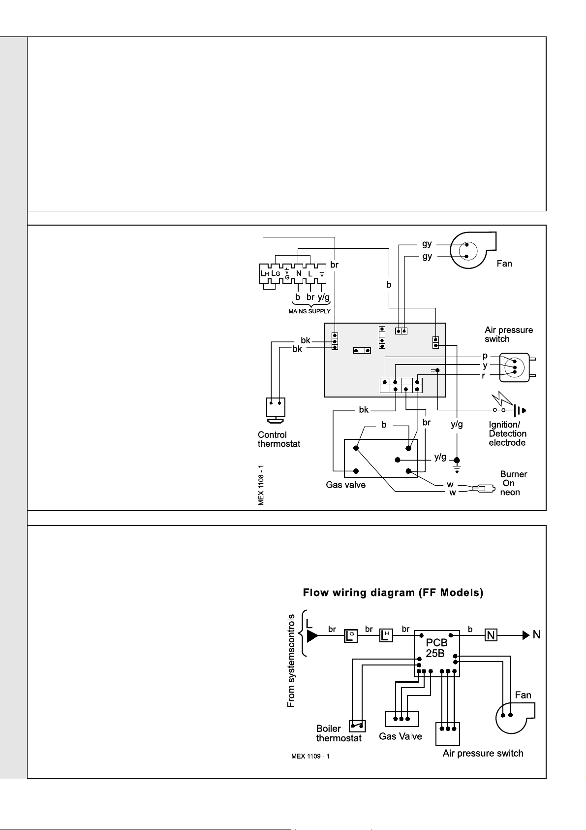
45
EXTERNAL CONTROLS
External wiring must be in accordance with the current I.E.E.
(BS 7671) Wiring Regulations.
The wiring diagrams illustrated in Frames 47-49 cover the
systems most likely to be fitted to this appliance.
For wiring external controls to the Mexico Super FF boiler
reference should be made to the system wiring diagrams
supplied by the relevant manufacturer, in conjunction with the
flow wiring diagram below and also Frame 46.
Difficulty in wiring should not arise, providing the following
directions are observed:
1. Controls that switch the system ON and OFF, e.g. a time
switch, MUST be wired, in series, in the live mains lead to
the boiler.
2. Controls that override an on/off control, e.g. a frost
thermostat, MUST be wired into the mains lead, in parallel,
with the control(s) to be overridden. Refer to Frame 50.
3. If a proprietary system is used, follow the instructions
supplied by the manufacturer.
p purple
b blue
gy grey
y/g yellow/green
Note. If there are no external controls the circulating pump
MUST be wired into the control box.
24
Mexico Super 40 FF - 80 FF - Installation
Page 25

46
PICTORIAL WIRING
INSTALLATION
INSTALLATION
Mexico Super 40 FF - 80 FF - Installation
LEGEND
w white
r red
bk black
br brown
p purple
b blue
gy grey
y/g yellow/green
25
Page 26

INSTALLATION
47
MID POSITION VALVE
Notes.
1. Some earth wires are omitted for clarity. Ensure proper
earth continuity when wiring.
2. Numbering of terminals on thermostats is specific to the
manufacturer indicated.
3. This is a fully controlled system - set the boiler
thermostat to maximum.
4. 'Switchmaster Midi' is similar in operation but the wiring
differs slightly; see manufacturer's literature.
Pumped only
INSTALLATION
LEGEND
b blue
bk black
48
TWO SPRING CLOSED VALVES
Notes.
1. Some earth wires are omitted for clarity. Ensure proper
earth continuity when wiring.
2. Numbering of terminals on thermostats is specific to the
manufacturer.
3. This is a fully controlled system - set the boiler
thermostat to maximum.
4. 'Switchmaster Autozone' has grey and orange auxiliary
switch leads but the ORANGE (NOT the grey) wire must
be connected to the incoming live supply.
LEGEND
b blue
bk black
br brown
r red
or orange
br brown
r red
w white
w white
gy grey
y/g yellow/green
Pumped only
or orange
y/g yellow/green
gy grey
49
HONEYWELL 'C' PLAN
Notes.
1. Some earth wires are omitted for clarity. Ensure proper
earth continuity when wiring
2. Numbering of terminals on thermostats is specific to the
manufacturer.
LEGEND
w white
r red
bk black
br brown
or orange
Gravity HW & Pumped CH
b blue
gy grey
y/g yellow/green
26
Mexico Super 40 FF - 80 FF - Installation
Page 27

INSTALLATION
50
FROST PROTECTION
Central heating systems fitted wholly inside the house
do not normally require frost protection as the house
acts as a 'storage heater' and can normally be left at
least 24 hrs. without frost damage. However, if parts of
the pipework run outside the house or if the boiler will
be left off for more than a day or so then a frost 'stat
should be wired into the system.
This is usually done at the programmer, in which case
the programme selector switches are set to OFF and
all other controls MUST be left in the running position.
The frost 'stat should be sited in a cold place but
where it can sense heat from the system.
Wiring should be as shown, with minimal disturbance
to other wiring of the programmer.
Designation of the terminals will vary, but the
programmer and thermostat manufacturer's leaflets will
give full details.
Diagram A shows a double pole frost thermostat, which
INSTALLATION
should suffice for all systems which do not use the OFF
terminals of the programmer.
Diagram B shows a 'change-over' frost thermostat, which will
cover most systems which do use CH OFF. If, however, on
such a system the HW pipework is in an isolated part of the
house, a second frost thermostat may be used to protect it.
If in doubt, ask your installer for advice.
51
FITTING THE CASING
1. Offer up the RH side panel, locating it with the
peg in the baseplate, and push the panel back
engaging it into the collector hood tab.
2. Secure the panel to the baseplate and turret
front panel.
3. Repeat steps 1 and 2 to refit the LH side
panel.
4. Place the top panel and push back.
5. Secure the top panel to the side panels.
IMPORTANT. Wiring within the boiler casing must
be neatly secured with the cable straps provided
and MUST NOT be allowed to touch the fan
cooling impellor, the burner front plate, or the
cleanout cover and the collector hood.
6. Replace the control box cover and refit the
control panel using the screws previously
removed.
Mexico Super 40 FF - 80 FF - Installation
7. Insert the thermostat phial and phial retaining clip
into the thermostat pocket. Take care not to kink the
thermostat capillary as it is unwound and secure it
with the split pin as shown.
8. Refit the in-line electrical connector between the
control box and the PCB box.
9. Refit the grille assembly
27
Page 28

52
COMMISSIONING AND TESTING
INSTALLATION
A. ELECTRICAL INSTALLATION
1. Checks to ensure electrical safety should be carried out by
a competent person.
2. ALWAYS carry out preliminary electrical system checks,
i.e. earth continuity, polarity, resistance to earth and short
circuit using a suitable test meter.
WARNING.
Whilst effecting the required gas soundness test and purging air from the gas installation,
open all windows and doors, extinguish naked lights and DO NOT SMOKE.
INSTALLATION
53
INITIAL LIGHTING
B. GAS INSTALLATION
1. The whole of the gas installation, including the meter,
MUST be inspected and tested for soundness, and purged
in accordance with the recommendations of BS. 6891.
2. Purging air from the gas installation may be expedited by
loosening the union on the gas service cock on the boiler
and purging until gas is detected.
3. Retighten the union and check for gas soundness.
LEGEND
A. Gas control valve.
B. Burner pressure test point.
C. Main burner pressure adjuster.
D. Inlet pressure test point.
E. Gas service cock.
F. Sightglass.
G. Boiler thermostat knob.
H. Main burner 'On' neon.
J. Overheat thermostat reset button
(optional).
TO LIGHT THE BOILER
1. Check that all the drain cocks are closed and any valves in
the flow and return are open.
2. Check that the gas service cock (E) is OPEN and the boiler
mains on/off switch is OFF.
3. If the boiler output is to be set to minimum or mid, affix the
appropriate indicator label supplied in the hardware pack to
the data plate.
4. Slacken the screw in the burner pressure test point (B) and
connect a gas pressure gauge via a flexible tube.
5. Switch the electricity supply ON and check that all external
controls are calling for heat.
6. Set the boiler thermostat knob (G) to position 6. The fan will
start. After the fan has run for a few seconds the pilot solenoid
valve should open and the intermittent spark commence,
continuing until the pilot is established. The main burner will
28
then cross-light smoothly. If this sequence does not occur,
refer to the Fault Finding section.
7. Test for gas soundness around ALL boiler gas components
using leak detection fluid.
8. Operate the boiler for 10 minutes to stabilise the burner
temperature.
9. The boiler is preset at the factory to its highest nominal
rating but can be range rated to suit the system design
requirements. Refer to Table 2 (page 3). Remove the
sealing cap and turn the adjusting screw clockwise to
increase/anticlockwise to decrease the pressure until the
required burner pressure is achieved.
Refit the sealing cap.
10. Set the boiler mains on/off switch to OFF.
11. Remove the pressure gauge and tube. Retighten the
sealing screw in the pressure test point.
12. Turn ON and check for gas soundness at the pressure
test point.
13. Refit the lower front panel and secure with the 2 fixing
screws.
Mexico Super 40 FF - 80 FF - Installation
Page 29

INSTALLATION
54
GENERAL CHECKS
Make the following checks for correct operation:
1. Turn the boiler thermostat OFF and ON to check that the
main burner is extinguished and relit in response.
2. Set the boiler thermostat knob to position 6 and operate
the mains on/off switch. Check that the main burner lights
and extinguishes in response.
3. Check that the programmer, if fitted, and all other system
controls function correctly.
Operate each control separately and check that the main
burner or circulating pump (as the case may be) responds.
4. Water circulation System
a. With the system HOT, examine all water connections
for soundness.
b. With the system still hot, turn off the gas, water and
electricity supplies to the boiler and drain down, in
order to complete the flushing process.
c. Refill and vent the system, clear all air locks and again
check for water soundness.
d. Balance the system.
5. Finally, set the controls to the user's requirements, refit the
lower front panel securing with the 2 fixing screws and
close the controls door.
WARNING. The boiler must not be operated with the casing removed.
Thermostat Flow Temperature
Knob Setting
2 60 140
3 66 150
4 71 160
5 77 170
6 82 180
Notes.
zz
z If an optional programmer kit is fitted refer
zz
to the separate Programmer Kit Installation
Instructions and Programmer Kit User's
Instructions.
zz
z The temperatures quoted are approximate
zz
and vary between installations.
o
C
o
F
INSTALLATION
55
HANDING OVER
After completing the installation and commissioning of the system the
installer should hand over to the householder by the following actions:
1. Hand the User's Instructions to the householder and
explain his or her responsibilities under the Gas Safety
(Installation and Use) Regulations 1994, Amendments
1996 or rules in force.
2. Draw attention to the lighting instruction label affixed to the
inside of the controls door.
3. Explain and demonstrate the lighting and shutting down
procedures.
4. The operation of the boiler and the use and adjustment of
ALL system controls should be fully explained to the
householder, to ensure the greatest possible fuel
economy consistent with household requirements of both
heating and hot water consumption.
Advise the User of the precautions necessary to prevent
damage to the system and to the building in the event of
the system remaining inoperative during frosty conditions.
5. Explain the function and the use of the boiler thermostat
and external controls.
6. Explain and demonstrate the function of time and
temperature controls, radiator valves etc., for the
economic use of the system.
7. If an optional Programmer Kit is fitted then draw attention
to the Programmer Kit User's Instructions and hand them
to the householder.
8. After installation, commissioning, and customer
hand-over instructions please complete the
the customer.
9. Stress the importance of regular servicing by a CORGI
registered installer and that a comprehensive service
should be carried out AT LEAST ONCE A YEAR.
appliance log book and leave this with
Mexico Super 40 FF - 80 FF - Installation
29
Page 30

SERVICING
56
SCHEDULE
WARNING.
BEFORE SERVICING always turn OFF the gas supply at the
gas service cock and switch OFF and DISCONNECT the
electrical supply to the appliance.
To ensure the continued safe and efficient operation of the
appliance it is recommended that it is checked at regular
intervals and serviced as necessary. The frequency of servicing
will depend upon the installation condition and usage but should
be carried out at least annually .
It is the law that any service work must be carried out by a
CORGI registered installer.
a. Light the boiler and carry out a pre-service check, noting
any operational faults.
b. Operate the boiler for at least 20 minutes. Check the gas
consumption.
c. Connect a suitable gas analyser to the sampling point on
the flue collector. Refer to Frame 60.
For correct operation the CO/CO
should not be greater than 0.004 ratio. If this is the case
and the gas input is within 95% of the nominal then no
further action need be taken. If not the case, proceed to
step (d)
content of the flue gas
2
d. Clean the main burner.
e. Clean the heat exchanger.
f. Clean the main injectors.
g. Check that the flue terminal is unobstructed and that the
flue system is sealed correctly.
h. If the appliance has been installed in a compartment, check
that the ventilation areas are clear.
The servicing procedures are covered more fully in Frames 58
to 62 and MUST be carried out in sequence.
Note. In order to carry out either servicing or replacement of
components, the boiler casing must removed. Refer to Frame
57.
IMPORTANT. After completing the servicing or exchange of
components always test for gas soundness and carry out
functional checks as appropriate.
When the work is complete the casing MUST be correctly
refitted and secured.
The boiler must NOT be operated if the casing is not fitted.
57
BOILER CASING REMOVAL
1. Remove the 2 screws and lift off the lower front panel.
2. Remove the 2 screws and lift off the grille assembly.
3. Disconnect the electrical leads from the gas valve.
4. Disconnect the inline connector on the PCB box lead.
SERVICING
5. Remove the thermostat phial
from the pocket as shown.
6. Remove the 2 screws securing
the control panel and pull down
to release the tabs from under
the top panel.
7. If the boiler is not fitted under a
work top, access for flue
cleaning will be improved by
removing the top panel.
30
Mexico Super 40 FF - 80 FF - Installation
Page 31

SERVICING
58
BURNER AND CONTROLS ASSEMBLY REMOVAL
1. Remove the 2 screws and lift off the lower
front panel. Refer to
Frame 57.
2. Remove the grille
assembly. Undo the
gas cock union.
3. Disconnect the
ignition lead from the
PCB.
4. Remove the 4 wing
nuts and withdraw the
burner and controls
assembly, complete,
from the boiler.
5. Place on a convenient
working surface.
59
CLEANING THE BURNER/PILOT ASSEMBLY
1. Brush off any deposits that may have fallen onto the
burner head (ensuring that the flame ports are
unobstructed) and remove any debris that may have
collected.
Note. Brushes with metallic bristles MUST NOT be
used.
2. Remove the main burner injector. Check, clean or
replace, as required.
3. Refit the injector, using an approved jointing compound.
4. Inspect the pilot burner and ignition/detection electrode;
ensure they are clear and in good condition.
Check that:
a. The pilot burner is clean and unobstructed.
b. The ignition/detection electrode is clean and
undamaged.
c. The ignition/detection lead is in good condition and
securely connected.
d. The spark gap is correct. Refer to Frame 69.
e. The position of the ignition/detection electrode relative
to the pilot burner is correct. Refer to Frame 69.
5. Clean or renew components as necessary.
SERVICING
60
CLEANING THE FAN/FLUE WAYS
1. Remove the silicon rubber tube from the fan sensing point.
2. Disconnect the fan leads.
3. Remove the M4 screw securing the flue connector to the
fan.
4. Slacken the M4 screw securing the flue connector to the
turret front panel.
5. Disconnect the silicon rubber tube from the top of the
collector hood.
6. Remove the 4 M4 screws on the top of the collector hood
and by sliding it forwards remove collector hood/fan
assembly.
7. Check that the fan impellor runs freely. Remove any debris
from the impellor with a soft brush.
8. Remove the flue baffles.
9. Remove all loose deposits from the heat exchanger,
particularly between the fins, using a suitable brush.
10. Re-assemble in reverse order. Lubricate fan 'O' ring with
silicon grease. Ensure the fan leads and 2 sensing tubes
are reconnected.
Mexico Super 40 FF - 80 FF - Installation
31
Page 32
61
RE-ASSEMBLY
SERVICING
Re-assemble the boiler in the following order.
1. Refit the flue baffles.
2. Inspect the collector hood rope gasket and replace, if
necessary, ensuring that the self adhesive rope is fitted
centrally on to the lip of the collector hood / fan assembly.
The boiler efficiency will be adversely affected if
incorrectly fitted. Refit the collector hood cover with the 4
screws. Tighten the screws. Ensure that the sealing
gasket is compressed. Refit the pressure pipe.
3. Refit the positive pressure tubes on the top of the fan
housing. Reconnect the electrical leads.
62
GAS PRESSURE ADJUSTMENT
1. Pilot Pressure
Pilot adjustment is factory set to maximum and no
adjustment is possible.
4. Refit the burner assembly.
5. Reconnect the gas supply and the electrical wiring.
Refer to Frames 39 & 43.
7. Check for gas soundness. Check the gas service cock
and pressure test point.
8. Refit the boiler casing (Refer to Frame 51).
9. Refit the lower front panel and secure with the 2 fixing
screws.
2. Main Burner Pressure
After servicing, reference should be made to Table 1,
which quotes details of the rated output with the
related burner pressure and heat input. Any required
adjustments should be made using the pressure
adjustment screw. Refer to Frame 53, 'Initial Lighting.
Refit the lower front panel and secure with the 2 fixing
screws.
REPLACEMENT OF PARTS
63
GENERAL
When replacing any component:
1. Isolate the electricity supply.
SERVICING
2. Turn OFF the gas supply.
3. Remove the lower front panel and grille assembly.
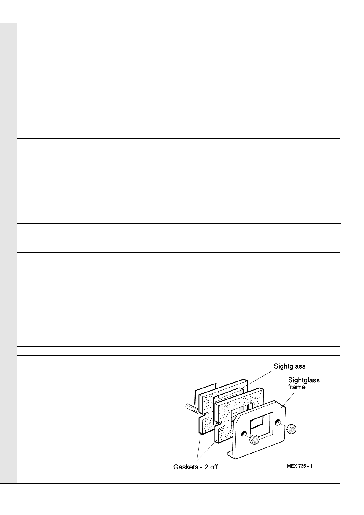
64
SIGHTGLASS REPLACEMENT
1. Unfasten the 2 M5 hexagon nuts and
washers. Remove the assembly from the front
plate.
2. Fit the new sightglass and re-assemble, as
shown.
3. Retighten the 2 M5 hexagon nuts to ensure an
airtight seal. Do NOT overtighten.
Note. In order to assist fault finding, the control box printed
circuit board is fitted with 2 indicator lights which represent
the following boiler conditions:
Neon I3. Mains electricity ON.
Neon SG1. Flashes to indicate ignition operation (stops
after detection).
The boiler MUST NOT be operated if the casing is not
fitted.
32
Mexico Super 40 FF - 80 FF - Installation
Page 33
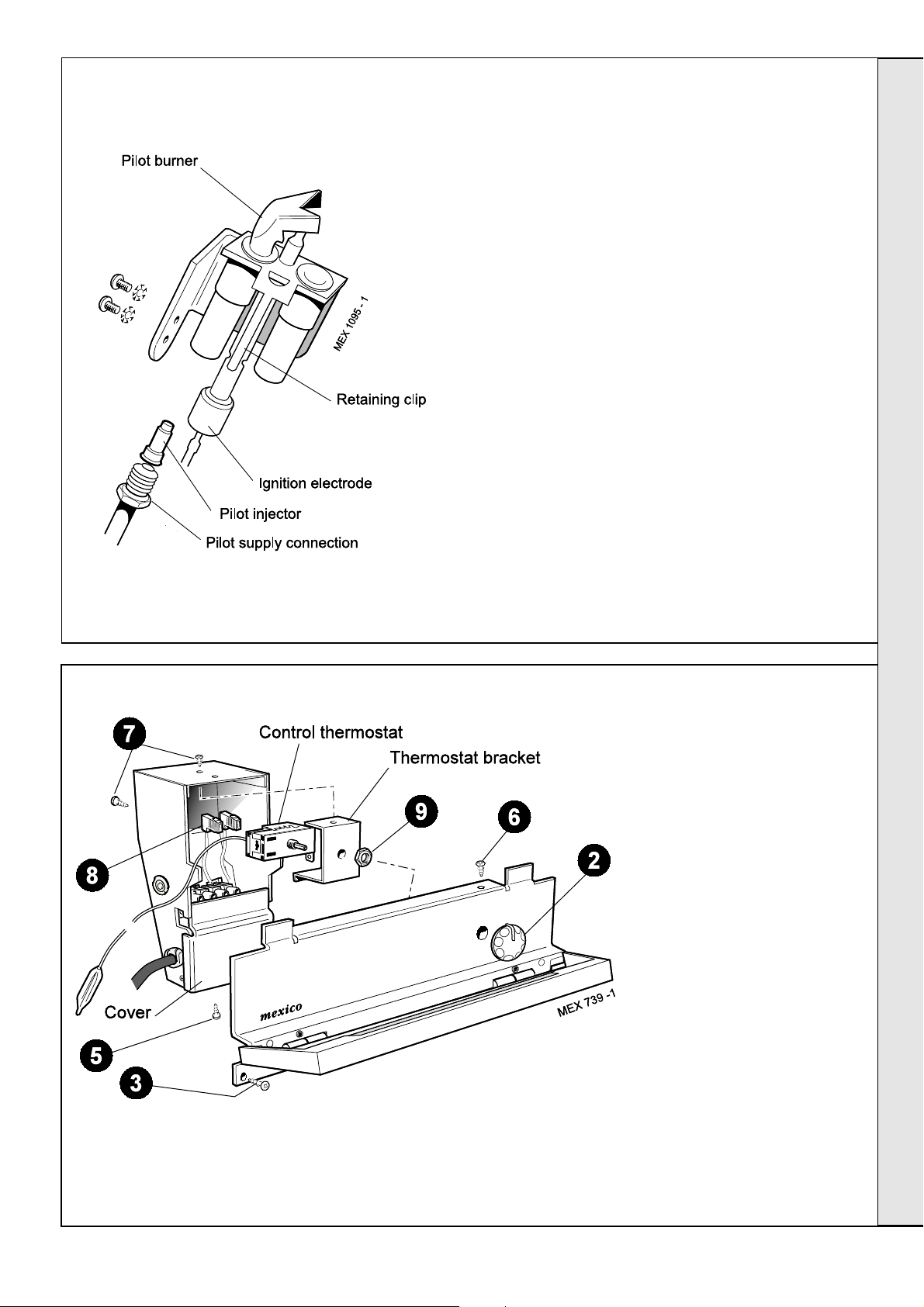
65
PILOT BURNER REPLACEMENT
SERVICING
1. Remove the 2 screws and lift off the lower front
panel then remove the grille assembly. Refer to
Frames 57.
Undo the gas cock union. Remove the 4 wing
nuts and withdraw the burner and controls
assembly, complete, from the boiler.
2. Disconnect the ignition lead from the PCB.
3. Prise the retaining clip out of the groove in the
electrode, using a small screwdriver, and
withdraw the electrode - refer to Frame 69.
4. Undo the pilot supply pipe connection and ease
clear of the pilot burner. DO NOT lose the pilot
injector, which is a push-fit in the pilot burner
housing.
5. Remove the 2 securing screws and washers,
and withdraw the pilot burner.
6. Fit the new pilot burner and re-assemble in
reverse order, ensuring that:
a. The injector is in position when refitting the
pilot supply.
b. A gas-tight joint is made.
c. The spark gap is correct. Refer to Frame 69.
66
CONTROL THERMOSTAT REPLACEMENT
1. Remove the 2 screws and lift
off the lower front panel.
Refer to Frame 57.
2. Pull off the thermostat knob.
3. Remove the 2 screws and pull
down the control panel tabs
clear of the top panel.
4. Remove the thermostat phial
from the pocket. Refer to
Frame 57.
5. Remove the bottom screw
and remove the cover.
6. Remove the top screw and
ease the control box off the
control panel.
7. Remove the 2 screws to
release the thermostat
bracket.
8. Disconnect the electrical
leads.
9. Unscrew the thermostat nut to
withdraw the thermostat.
10. Fit the new thermostat and reassemble in reverse order.
SERVICING
Mexico Super 40 FF - 80 FF - Installation
33
Page 34
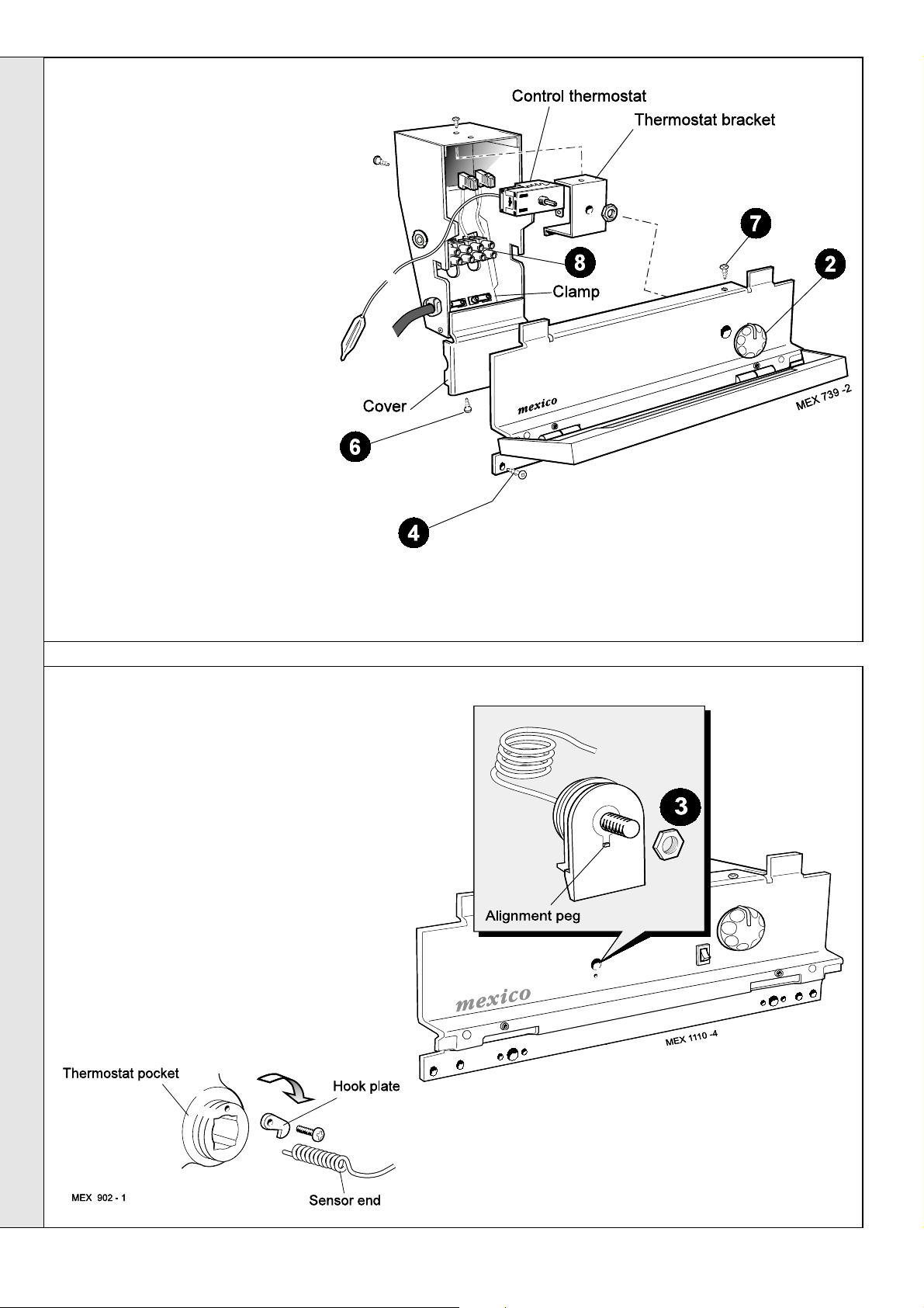
SERVICING
67
CONTROLS PANEL REPLACEMENT
1. Remove the 2 screws and lift off the
lower front panel. Refer Frame 57.
2. Pull off the thermostat knob.
3. Disconnect the inline electrical
connector between the control box and
PCB box.
4. Unscrew the 2 screws and pull down
the control panel so that the 2 tabs
clear the top panel.
5. Remove the thermostat phial from the
pocket. Refer to Frame 57.
6. Remove the bottom screw and remove
the cover from the control box.
7. Remove the top screw and ease the
control box off the control panel.
8. Disconnect the mains electrical supply
from the terminal strip and release from
its clamp.
9. Assemble new control box and panel
and fit to the casing in reverse order.
10. Insert control thermostat phial into
pocket and secure with the split pin.
11. Refit the inline electrical connector
between the control box and the PCB box.
12. Remove control box cover and make electrical supply
connections to the terminal strip. Refer to Frame 46.
13. Replace the lower front panel and secure with the 2 fixing
screws.
14. Check the operation of the boiler.
68
OVERHEAT THERMOSTAT REPLACEMENT (if fitted)
1. Remove the 2 screws and lift off the lower front
panel. Refer to Frame 57.
SERVICING
2. Slacken the screw at the thermostat pocket and
withdraw the phial from the pocket.
3. Remove the thermostat retaining nut and withdraw
the thermostat from the control panel.
4. Transfer the electrical leads from the old thermostat
to the replacement (polarity is not important).
5. Fit the new thermostat ensuring that the alignment
peg on the thermostat sits in the small hole adjacent
to the main fixing hole and reassemble in reverse
order.
6. Replace the lower front panel and secure with the 2
fixing screws.
7. Check the operation of the boiler.
34
Mexico Super 40 FF - 80 FF - Installation
Page 35
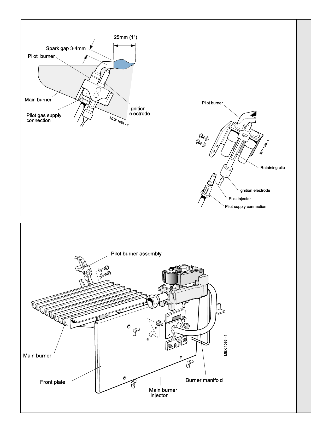
SERVICING
69
IGNITION ELECTRODE AND LEAD REPLACEMENT
1. Remove the 2 screws and lift off the lower front
panel then remove the grille assembly - refer to
Frame 57. Undo the gas cock union. Remove the 4
wing nuts and withdraw the burner and controls
assembly, complete, from the boiler.
2. Disconnect the ignition lead from the PCB.
3. Prise the retaining clip out of the groove in the
electrode, using a small screwdriver, and withdraw
the electrode.
Detail of pilot flame
length and spark gap
70
MAIN BURNER REPLACEMENT
4. Push in the new
electrode until the
retaining clip locates
in the groove and reassemble in reverse
order.
1. Remove the 2 screws
and lift off the lower front
panel then remove the
grille assembly. Refer to
Frame 57.
Undo the gas cock
union. Remove the 4
wing nuts and withdraw
the burner and controls
assembly, complete,
from the boiler.
2. Disconnect the ignition
lead from the PCB.
3. Remove the 2 screws
securing the pilot burner
and pull the assembly
clear of the main burner.
4. Remove the 2 nuts and
washers securing the
burner to the front plate
and manifold. Withdraw
the burner.
5. Fit the new burner and
re-assemble in reverse
order, taking care not to
damage the main burner
injector which is screwed
into the burner manifold.
SERVICING
Mexico Super 40 FF - 80 FF - Installation
35
Page 36

71
MAIN BURNER INJECTOR REPLACEMENT
1. Remove the 2 screws and lift off the lower front
panel then remove the grille assembly. Refer to
Frame 57.
Undo the gas cock union. Remove the 4 wing nuts
and withdraw the burner and controls assembly,
complete, from the boiler.
2. Disconnect the ignition lead from the PCB.
3. Undo the pilot supply connection.
4. Undo the manifold securing nuts and remove the
manifold from the front plate.
5. Unscrew the burner injector from the manifold.
6. Fit the new injector, using an approved jointing
compound, and re-assemble in reverse order.
SERVICING
72
GAS VALVE REPLACEMENT
1. Remove the 2 screws and lift off the lower front panel then
remove the grille assembly - refer to Frame 57.
Undo the gas cock union. Remove the 4 wing nuts and
withdraw the burner and controls assembly, complete,
from the boiler.
SERVICING
2. Disconnect the ignition lead from the PCB.
3. Undo the pilot supply connection.
4. Unscrew the gas inlet pipe from the valve.
5. Remove the 4 securing screws and withdraw the valve
from the burner manifold.
6. Fit the new gas valve, ensuring that:
a. The valve is fitted the correct way round - an arrow
engraved on the valve indicates the direction of flow.
b. The sealing 'O' ring supplied with the valve is correctly
fitted at the outlet flange.
c. An approved jointing compound is used when
reconnecting the gas inlet pipe.
36
Mexico Super 40 FF - 80 FF - Installation
Page 37

SERVICING
73
FAN REPLACEMENT
1. Remove the lower front panel, control panel and top panel -refer to Frame 57.
2. Remove the silicon rubber tube from the fan sensing point.
3. Disconnect the fan leads.
4. Remove the M4 screw securing the flue connector to the fan.
5. Slacken the 2 M4 screws securing the flue connector
to the turret front panel.
6. Disconnect the silicon rubber tube from the top of the
collector hood.
7. Remove the 4 M4 screws on the top of the collector
hood and by sliding it forwards remove collector hood
/ fan assembly.
8. Remove the three M4 screws retaining the fan to the
collector hood.
9. Re-assemble in reverse order. Lubricate the fan 'O'
ring with silicon grease. Ensure the fan leads and 2
sensing tubes are reconnected.
10. Refit the boiler casing.
11. Check the boiler operation.
74
AIR PRESSURE SWITCH (APS) REPLACEMENT
1. Remove the lower front panel, control panel and the top
panel -refer to Frame 57.
2. Remove the APS fixing screw.
3. Remove both sensing tubes from the APS.
4. Remove the 3 electrical connections from the APS.
5. Connect the new APS in reverse order.
6. Refit the APS with the fixing screw.
7. Refit the boiler casing.
8. Check the boiler operation.
75
PRINTED CIRCUIT BOARD (PCB) REPLACEMENT
SERVICING
1. Remove the 2 screws and lift off the lower
front panel - refer to Frame 57.
2. Undo the PCB cover fixing screw and
remove the cover.
3. Remove the HT lead from the PCB.
4. Remove the 6 push-in connectors from
the PCB.
5. Compress the barbs on the PCB standoffs to release the PCB from the box
6. Fit the new PCB and re-assemble in
reverse order.
7. Refit the boiler casing.
8. Check the operation of the boiler.
Mexico Super 40 FF - 80 FF - Installation
37
Page 38
FAULT FINDING
START
Check that the mains on neon
'I3' is illuminated.
YES
Is there a live supply to both
terminals of overheat 'stat?
(if fitted)
YES
Check that the boiler thermostat
is set at maximum and the mains
on/off switch is ON.
Is the fan turning ?
YES
Is there a supply on the fan
Is there a
supply at
the fan ?
NO
connector at PCB ('Molex '
marked 'FAN'?).
YES
YES
NO
Check mains supply and fuses.
NO
NO
NO
Change fan
Rectify bad connection
Check programmer and system
thermostats are all ON. Check that
boiler connections are OK .
Can the overheat 'stat
Has the fuse blown on PCB ?
Is there a live supply on the
violet lead to pressure switch?
be reset when the
system is cold ?
Is there continuity
across the control
thermostat ?
NO
NO
YES
Is there a live
supply on the red
lead to pressure
switch?
YES
YES
NO
NO
YES
NO
YES
Reset the overheat 'stat. Set control
'stat to maximum. Allow the boiler
to reach temperature - if the
overheat 'stat trips again, measure
flow temperature.
If above 90°C replace control 'stat.
If below 90°C replace overheat 'stat.
Replace the overheat thermostat
Replace the boiler thermostat
Replace fuse BUT, before
attempting to start boiler, check
for short between live and
neutral, also between live and
earth, on all items plugged into
PCB
Check all connections to PCB.
If no error found, replace PCB.
Check connections and leads to
pressure switch/boiler thermostat
and check that fan is operating.
Is the ignition electrode sparking?
YES
Does the pilot light ?
NO
Is there a gas supply
to the boiler?
YES
Is the pilot injector
blocked?
NO
Ensure pilot and
main gas valve
leads are not
crossed over.
Is there a supply
voltage at pilot
gas valve?
YES
Replace
FAULT FINDING
gas valve
NO
Check the continuity of
connector to electrode.
cease when gas is lit ?
Check all connections to PCB.
If no fault found, replace PCB
YES
Does the
spark stop
after pilot is
lit?
NO
Check the polarity of
the mains supply.
the ignition lead from
Does the spark now
YES
NO
NO
Is there a regular
spark from tube 'SG1'
on the PCB?
NO
Does main burner
cross-light from pilot?
NO
Is there a supply on
terminals of main gas
valve?
NO
Is the main burner
injector clear?
Replace main gas
solenoid valve
YES
YES
YES
Check connections to pressure
switch. If no faults found, change
pressure switch.
Check gap at ignition electrode.
Check electrode and lead are
undamaged, and not close to
earthed metalwork.
Check all connections to PCB.
If no fault found change PCB.
Check pressure switch sensing
pipes for blockages, bad
connections and reversed
connection.
Is pressure difference at switch
greater than 0.9 mbar?
YES
Change
pressure switch
NO
Change fan
38
Mexico Super 40 FF - 80 FF - Installation
Page 39

SHORT LIST OF PARTS
The following are parts commonly required as replacement
components, due to damage or expendability. Their failure or
absence is likely to affect safety or performance of this
appliance.
The list is extracted from the British Gas List of Parts, which
contains all available spare parts.
The full list is held by British Gas, Caradon Plumbing Limited
distributors and merchants.
Key No. G.C. Part No. Description Qty. Product No.
14 Fan assembly: 40-50-60-70-80 FF 1 079888
17 319 494 Sightglass assembly 1 079 334
20 Main burner:
385 876 AEROMATIC No. AC 19/123 266; 40 FF 1 113 187
385 877 AEROMATIC No. AC 19/123 267; 50 FF & 60 FF 1 113 188
382 957 AEROMATIC No. AC 19/123 244; 70 FF & 80 FF 1 013 857
When ordering spares please quote:
1. Boiler model
2. Appliance G.C. number
3. Description
4. Quantity
5. Product no.
21 Main injector:
398 051 BRAY Cat. 10 - size 1200; 40 FF 1 004 190
398 055 BRAY Cat. 10 - size 1400; 50 FF 1 003 361
398 059 BRAY Cat. 10 - size 1700; 60 FF 1 004 305
398 064 BRAY Cat. 10 - size 2200; 70 FF 1 004 049
398 065 BRAY Cat. 10 - size 2300; 80 FF 1 004 760
22 E01-505 Pilot burner / injector / fittings:
HONEYWELL Q 385 A 2036; 1 075 291
23 381 656 Pilot injector: HONEYWELL 4500 4108 001 1 003 825
24 Gas valve assembly:
VR 4601AA 1010 and 'O'ring 40-50-60-70-80 FF 1 170 663
26 386 575 Ignition electrode: HONEYWELL 45900413-004 1 151 079
27 HT lead: 900 mm 40-50-60-70-80 FF 1 058826
30 PCB sub assembly 1 170 665
38 Pressure switch: HONEYWELL C6065F1316B 1 152427
49 Flue baffle kit 40 FF 2 079890
50 FF, 60 FF 4 079891
70 FF, 80 FF 4 079890
66 Thermostat - RANCO K36 - P1354 1 151 903
67 308 557 Thermostat knob 1 111 904
Mexico Super 40 FF - 80 FF - Installation
39
Page 40
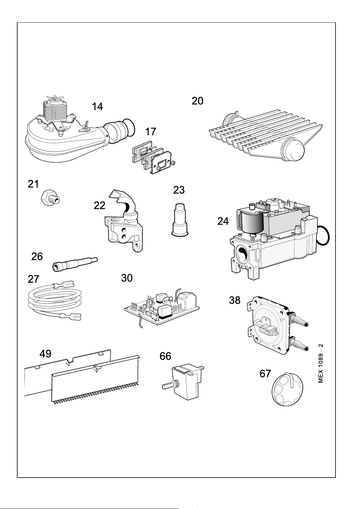
SHORT PARTS
76
LIST OF PARTS
40
Mexico Super 40 FF - 80 FF - Installation
Page 41

LIST OF PARTS
77
BOILER CONTROL PANEL - Exploded View
Legend.
63. Control panel complete assy.
65. Control box assy.
66. Control thermostat.
67. Control thermostat knob.
71. Control front panel (door).
72. Magnetic strip.
Mexico Super 40 FF - 80 FF - Installation
41
Page 42

PCB BOX - Exploded View
78
Legend.
29. PCB Chassis assembly.
30. PCB sub-assembly.
34. PCB support
37. PCB cover.
LIST OF PARTS
42
Mexico Super 40 FF - 80 FF - Installation
Page 43

LIST OF PARTS
79
BURNER AND CONTROLS ASSEMBLY - Exploded View
Legend.
16. Front plate assy.
17. Sightglass assy.
18. Burner manifold.
19. Pilot pipe.
20. Main burner.
21. Main injector.
22. Pilot burner.
24. Gas valve.
25. 'O' ring.
26. Ignition electrode.
27. Ignition Iead.
28. Gas cock.
50. Sealing gasket.
51. Sealing plate.
Mexico Super 40 FF - 80 FF - Installation
43
Page 44

80
BOILER CASING ASSEMBLY
Legend.
46. Baseplate.
62. Casing complete.
63. Controls panel complete.
71. Controls front panel (door)
73. Side panel - LH
74. Side panel - RH
75. Lower front panel.
76. Top panel.
77. Grille assy.
LIST OF PARTS
44
Mexico Super 40 FF - 80 FF - Installation
Page 45

Mexico Super 40 FF - 80 FF - Installation
45
Page 46

THIS SYMBOL IS YOUR
ASSURANCE OF QUALITY
The code of practice for the installation,
commissioning & servicing of central heating systems
These appliances are designed for use with Natural
Gas only. They have been tested and conform with the
provisions of BS. 6332 and BS. 5258.
Technical Training
The Caradon Plumbing Technical Training Centre offers a
series of first class training courses for domestic,
commercial and industrial heating installers, engineers and
system specifiers. For details of courses please ring:
..................................................................... 01270 413624
Caradon Plumbing Ltd., P.O. Box 103, National Ave, Kingston upon Hull, HU5 4JN. Telephone:
01482 492 251 Fax: 01482 448 858. Registration No. London 322 137. Registered Office: National
Avenue, Kingston upon Hull, HU5 4JN. A subsidiary of Caradon p.l.c
I
deal Installer/Technical Helpline: 01482 498663
CERTIFIED PRODUCT
Manufactured under a BS EN ISO 9001:
1994 Quality System accepted by BSI
Caradon Plumbing Ltd. pursues a
policy of continuing improvement in
the design and performance of its
products. The right is therefore
reserved to vary specification
without notice.
January 2000 UIN 153 419 A03
46
Mexico Super 40 FF - 80 FF - Installation
Page 47

YOUR FEEDBACK
and your chance to win a free boiler
At Ideal we've been leaders in the design and engineering of robust and reliable
boilers for over 90 years. We want to continue as leaders by listening to your
suggestions for how to improve our boilers and our service. We will be giving
away a free boiler for the five best ideas every year (to be selected by our
Technical Director). Please complete this form, using extra sheets if required,
and post it or fax it to us on 01482 498699.
Boiler details
Model / Size (e.g. Classic RS 230, Mexico CF 3/60 etc. Details on control panel door)
Date of Installation
Installer details
Name
Address
Post Code Telephone (Please include STD code)
How I would improve this boiler:
My general comments for Ideal:
:
I
deal Installer/Technical Helpline: 01482 498663
Mexico Super 40 FF - 80 FF - Installation
47
Page 48
Further information
If you would like information about Ideal Boilers please complete this
sheet and fax it to us on 01482 498699 or post it to Caradon Plumbing
Limited, PO Box 103, National Avenue, Kingston upon Hull, HU5 4JN.
Installer details
Name
Address
Post Code Telephone (Please include STD code)
General information required
Please send me details of Ideal Training Courses.
Please arrange for a technical representative to contact me.
Please arrange for me to join an Ideal factory tour.
Range guides required
The Ideal Guide: a specifier's and installer's introduction to the
Ideal domestic boiler range.
The Ideal Householders Guide: to assist the installer when
presenting to his/her customers.
Technical manuals required
The Ideal C class combi boiler
The Ideal Classic wall hung boiler
The Ideal Classic System wall hung boiler
The Ideal Classic LX Deluxe wall hung boiler
The Ideal Mexico floor standing boiler
The Ideal Minimiser heat-saving boiler
The Ideal Response combi boiler
The Ideal Response SE super efficiency combi boiler
The Ideal Systemiser SE super efficiency system boiler
The Ideal Concord high output boiler
The Ideal Buccaneer oil fired boiler
Caradon Plumbing Ltd, PO Box 103, National Avenue, Kingston upon Hull, HU5 4JN. Telephone: 01482 492251 Fax: 01482 448858.
I
deal Installer/Technical Helpline: 01482 498663
U.I.N. 153419 A0
 Loading...