

Page 1

Page 2

Mexico:
The Floor Standing Gas Boiler
The Ideal Mexico is a range of cast iron floor standing gas central heating boilers. Both
balanced or conventional flue versions are available. A complete range of both natural
gas and propane models. The range offers Super models and, for when space is tight,
there are Slimline models available.
Mexico: Britain’s biggest selling floor standing boiler
The ideal replacement boiler...
Easy to install, easy to operate and easy to service. The Ideal Mexico really is the
ultimate replacement floor standing range - you can depend on it.
Proven reliability...
Proven cast iron heat exchanger engineered and refined to be the most dependable
floor standing boiler ensuring totally calm operation and quiet running, whatever the
system demands.
Complete range...
27 models, including 4 Slimline models at only 250mm wide and 8 propane Super
models. Option kit availability includes an easy to use programmer kit available on all
models, an overheat thermostat kit for all models and a pump kit that can be housed
within the casing, available for all models except the Super CF 3/140 & CF 3/140P.
Full system suitability...
All models are suitable for connection to pumped open vent central heating systems,
pumped central heating combined with pumped or gravity indirect domestic hot water
supply systems. They can also be used on sealed water systems when used in
conjunction with the optional Overheat Thermostat Kit.
Free Guarantee: 1st Year Ideal Care
The home owner is entitled to 12 months free Ideal Care, which includes both parts
and labour, to restore the boiler to full function. Please encourage the home owner to
complete and return the registration form in their Householder’s pack within 30 days of
installation.
Optional Extra Year Cover with Ideal Care
You may wish to offer your own annual service plan or you may wish to advise the
home owner to complete their application form for the appropriate level of extended
Ideal Care - Silver, Gold or Platinum. Full details are available in the Ideal Care brochure.
CAUTION.
this appliance, care should be taken when handling edges of sheet steel components.
2
To avoid the possibility of injury during the installation, servicing or cleaning of
Mexico Slimline CF 3/40 & 3/50 - Installation
Page 3

GENERAL
Table 1 - General Data
Boiler Size CF 3/40 CF 3/50
Gas Supply Connection in. BSP Rc 1/2 (1/2)
Flow and Return Connections Rc 1 (1" BSP)
MAXIMUM Static Water Head m (ft.) 30.5 (100) (3 bar)
MINIMUM Static Water Head m (ft.) 1.0 (3.3)
Electrical Supply power consumption 230 V ~ 50 Hz 5W
External Fuse Rating 3 A
Water Content litre (gal.) 20 (4.4)
Dry Weight excluding balanced flue terminal kg. (lb.) 94 (207)
Boiler Size Height mm (in.) 850 (33.5)
Width mm (in.) 255 (10.0)
Depth mm (in.) 535 (21.0)
Gas Type Natural 2 H
Gas Supply Pressure 20 mb
Table 2 - Performance Data
Boiler Size CF 3/40 CF 3/50
Boiler Input MINIMUM kW (Btu/h) 11.3 (38 700) 15.0 (51 100)
Gas Consumption l/s (ft.3/h) 0.29 (37) 0.39 (49)
MID kW (Btu/h) 13.2 (44 900) 17.0 (57 900)
3
Gas Consumption l/s (ft.
/h) 0.34 (43) 0.44 (56)
MAXIMUM kW (Btu/h) 14.9 (50 800) 18.7 (63 700)
3
Gas Consumption l/s (ft.
/h) 0.38 (49) 0.48 (61)
Boiler Output MINIMUM kW (Btu/h) 8.8 (30 000) 11.7 (40 000)
to Water MID kW (Btu/h) 10.3 (35 000) 13.2 (45 000)
MAXIMUM kW (Btu/h) 11.7 (40 000) 14.7 (50 000)
Burner Setting MINIMUM mbar (in w.g.) 6.3 (2.5) 7.8 (3.1)
Pressure (hot) MID mbar (in w.g.) 9.0 (3.6) 10.3 (4.1)
MAXIMUM mbar (in w.g.) 11.2 (4.5) 12.5 (5.0)
Flue gas flow rate (maximum) g/s 7.0 8.8
o
Flue gas temperature
C94 118
*Seasonal Efficiency (SEDBUK) % 70.5 71.4
*The value is used in the UK government's Standard Assessment Procedure (SAP) for energy rating of dwellings.
The test data from which it has been calculated have been certified by BGplc 0087)
Note.
Gas consumption is calculated using a calorific
value of 38.7 MJ/m3 (1038 Btu/ft3) gross or 34.9
MJ/m3 (935 Btu/ft3) nett
To obtain the gas consumption at a different
calorific value:-
a. For l/s - divide the gross heat input (kW) by
the gross C.V. of the gas (MJ/m
3
).
b. For ft3/h - divide the gross heat input (Btu/h)
by the gross C.V. of the gas (Btu/ft3).
Mexico Slimline CF 3/40 & 3/50 - Installation
Key to symbols
GB = United Kingdom IE = Ireland (Countries of destination)
PMS = Maximum operating pressure of water
= An appliance designed for connection to a flue discharging the
B
11BS
products of combustion outside the room, with air for combustion
being drawn directly from the room where the appliance is installed,
without a fan in the combustion products circuit and fitted with a
combustion products discharge safety device.
I2H= An appliance designed for use on 2nd Family gas, Group H only.
3
Page 4

CONTENTS
Air Supply....................................................................... 7
Boiler Assembly - Exploded view ................................ 9
Mexico Slimline
Mexico Slimline CF 3/40 G.C. No. 41 348 01
Mexico Slimline CF 3/50 G.C. No. 41 348 03
Boiler Clearances .......................................................... 6
Burner Assembly - Exploded view ............................ 34
Electrical Connections ............................................... 15
Electrical Diagrams ..................................................... 15
Electrical Supply ........................................................... 8
Fault Finding ............................................................... 31
Flue Connection .......................................................... 15
Flue Installation ............................................................. 7
Frost Protection .......................................................... 18
Gas Safety Regulations ................................................ 5
Gas Supply .................................................................... 6
Initial Lighting.............................................................. 20
B.G. Certified - P.I. No. 87 AT 15
Destination Countries: GB and IE
Natural Gas only Appliance type: B11 BS
INTRODUCTION
The Mexico Slimline range is of floor standing, conventional
flue gas boilers. They are range-rated to provide central heating
outputs of:
CF 3/40 8.8 kW (30,000 Btu/h) to 11.7 kW (40,000 Btu/h).
CF 3/50 11.7 kW (40,000 Btu/h) to 14.7 kW (50,000 Btu/h).
The boiler has a cast iron heat exchanger and is supplied fully
assembled, complete with a white enamelled mild steel casing.
The boiler thermostat control is located behind the upper front
panel (drop down door).
The boilers are suitable, as standard, for connection to openvented systems ONLY.
The systems may be:
Installation ..................................................................... 9
Mandatory Requirements ............................................. 5
Pump ............................................................................ 13
Servicing ...................................................................... 22
Short List of Parts ....................................................... 32
System Electrical Diagrams ....................................... 17
Thermostatic Radiator valves. ..................................... 8
TTB Thermostat. ........................................................... 7
Water Circulation .......................................................... 7
Water Systems ............................................................ 13
Water Treatment ............................................................ 8
z pumped or gravity circulating indirect DHW only
z pumped central heating only
z pumped central heating combined with either a pumped or
gravity circulating indirect DHW circuit.
OPTIONAL EXTRA KITS
Programmer Kit Fits neatly within the casing. Separate
fitting instructions are included with this kit.
Overheat Available to allow the boiler to be used
Thermostat Kit on sealed water systems.
NOTE TO THE INSTALLER:
LEAVE THESE
INSTRUCTIONS ADJACENT TO THE GAS METER.
ALSO COMPLETE THE BENCHMARK LOG BOOK
AND GIVE THIS TO THE CUSTOMER.
4
Mexico Slimline CF 3/40 & 3/50 - Installation
Page 5

GENERAL
GAS SAFETY
Gas Safety (Installation and Use) Regulations 1994,
amendments 1996 or rules in force.
It is law that all gas appliances are installed by a CORGI registered
installer (identified by
Failure to install appliances correctly could lead to prosecution. It
is in your own interest, and that of safety, to ensure the law is
complied with.
The installation of the boiler MUST also be in accordance with the
latest I.E.E. (BS 7671) Wiring Regulations, local building
regulations, bylaws of the local water authority, the Building
Regulations and Building Standards (Scotland) and any relevant
requirements of the local authority.
Detailed recommendations are contained in the following British
Standard Codes of Practice:
BS. 6891 Low pressure installation pipes.
BS. 6798 Installation of gas fired hot water boilers of rated
input not exceeding 60 kW.
BS. 5449:1 Forced circulation hot water systems (small bore and
microbore domestic central heating systems).
BS. 5546 Installation of gas hot water supplies for domestic
purposes (2nd Family Gases).
BS. 5440: 1 Flues for gas appliances of rated input not
exceeding 60 kW.
BS. 5440: 2 Ventilation for gas appliances of rated input not
exceeding 60 kW.
BS 7593 Treatment of water in Domestic Hot Water Central
Heating Systems.
) in accordance with the above regulations.
Health and Safety Document No. 635.
The Electricity at Work Regulations, 1989.
Manufacturer’s notes must NOT be taken in any way as overriding
statutory obligations.
IMPORTANT. These appliances are certificated by the British
Standards Institution for safety and performance. It is important,
therefore, that no external control devices, e.g. flue dampers,
economisers etc., are directly connected to these appliances unless
covered by these Installation and Servicing Instructions or otherwise
recommended by Caradon Plumbing Limited in writing. If in doubt
please enquire.
Any direct connection of a control device not approved by Caradon
Plumbing Limited could invalidate the BSI Certification and the
normal appliance warranty. It could also infringe the Gas Safety
Regulations and the above regulations or other statutory
requirements.
LOCATION OF BOILER
The boiler must be installed on a flat and level floor, capable of
adequately supporting the weight of the boiler and any ancillary
equipment.
The boiler may be fitted on a combustible floor.
Insulation is not necessary, unless required by the local authority.
The boiler must not be fitted outside.
The boiler must not be installed in a bedroom or in a room
containing a bath or shower.
1
BOILER WATER CONNECTIONS
1. This appliance is NOT suitable for use
in a direct hot water system.
2. If the boiler is to be used on a sealed
system, an Overheat Thermostat Kit
is available and must be installed in
accordance with the instructions
supplied with the kit.
3. All water connections are Rc1
(1" BSP). The front top and bottom
plugged connections must not be
used. 2 spare blanking off plugs are
provided, in the hardware pack, for
use as necessary in the rear flow or
return water connections.
4. Pipework connections to all systems
may use flow and return connections
on the same side, or opposite sides of
the boiler.
That is:
Fully pumped system
In a fully system, either a LH or a RH flow
connection, together with LH or RH return
connection, may be used.
Gravity domestic hot water and
pumped central heating.
In a gravity DHW and pumped CH
system separate flow and return
connections are used for each service.
The use of a cylinder thermostat is
recommended. This will prevent
excessive domestic hot water
temperatures.
Mexico Slimline CF 3/40 & 3/50 - Installation
5
Page 6

GENERAL
Timber Framed Buildings
If the boiler is to be fitted in a timber framed building it should be
fitted in accordance with the Institute of Gas Engineering
document IGE/UP/7:1998.
Compartment Installations
A compartment used to enclose the boiler MUST be designed
and constructed specially for this purpose.
An existing cupboard or compartment may be used, providing it
is modified for the purpose.
Details of essential features of cupboards/compartment design,
including airing cupboard installation, are to conform to the
following:
zz
z BS. 6798.
zz
zz
z The position selected for installation MUST allow
zz
adequate space for servicing in front of the boiler
and for air circulation around the boiler.
z This position MUST also permit the provision of a
satisfactory flue and an adequate air supply.
z For the minimum clearances required for safety, and
subsequent service, see Frame 2.
GAS SUPPLY
The local gas supplier should be consulted, at the installation
planning stage, in order to establish the availability of an
adequate supply of gas. An existing service pipe must NOT be
used without prior consultation with the local gas supplier.
The boiler is to be installed only on a gas supply with a
governed meter.
A gas meter can only be connected by the local gas supplier or
by a local regional contractor.
Check that the appliance is suitable for the proposed gas
supply. An existing meter should be checked, preferably by the
gas supplier, to ensure that the meter is adequate to deal with
the rate of gas supply required. A minimum gas pressure of
20mbar MUST be available at the boiler inlet, with the boiler
operating.
Installation pipes MUST be fitted in accordance with BS. 6891.
Pipework from the meter to the boiler MUST be of an adequate
size. Do not use pipes of a smaller size than the boiler gas
connection.
The complete installation MUST be tested for gas soundness
and purged as described in the above code.
2
FLOOR MOUNTING AND BOILER CLEARANCES
Flammable materials must not be placed in
close proximity to the appliance. Materials
giving off flammable vapours must not be
stored in the same room as the appliance.
FLOOR MOUNTING
1. The floor must be flat, level and of
suitable load bearing capacity.
2. The back of the boiler may be fitted
up to the wall.
BOILER CLEARANCES
The minimum overall dimensions of the space in which the
boiler is to operate and to facilitate servicing are as follows:
Boiler Clearances Top One side Aggregate Total
'A' or 'B' 'A' + 'B' Width C
CF 3/40 & CF 3/50 20 (3/4") 25 (1") 100 (4") 350 (14")
IMPORTANT.
A MINIMUM clearance of 25mm (1") MUST also be maintained
between the flue pipe and any adjacent combustible material.
6
In addition a MINIMUM clearance of 533 mm (21") MUST
be available at the front of the boiler, for servicing.
Mexico Slimline CF 3/40 & 3/50 - Installation
Page 7

GENERAL
FLUE INSTALLATION
The flue must be installed in accordance with the recommendations
of BS. 5440:1.
The following notes are intended for general guidance:
1. The cross-sectional area of the flue, serving the boiler, MUST
NOT be less than the area of the flue outlet of the boiler.
If flue pipe is to be used it MUST NOT be less than the diameter
of the flue outlet connection on the boiler.
2. Flue pipes and fittings should be constructed from one of the
following materials:
a. Aluminium or stainless steel.
b. Cast iron, coated on the inside with acid resistant vitreous
enamel.
c. Other approved material.
3. If twin walled flue pipe is used it should be of a type
acceptable to British Gas.
4. If a chimney is to be used it should preferably be one that is
composed of, or lined with, a non-porous acid resistant
material.
Notes.
Chimneys lined with salt -glazed earthenware pipes are
acceptable if the pipes comply with BS.65 and BS.5440:1.
A flue pipe constructed from one of the materials listed in
2 a-c should form the initial connection to the lined
chimneys.
Where a chimney is to be used that is not composed of, or
lined with, a non-porous, acid resistant material it should be
lined with a stainless steel flexible flue liner which complies
with BS.715.
5. Before connecting the boiler to, or inserting a liner into, a flue
that has been previously used then the flue MUST be
thoroughly swept clean of any soot or loose material. If a
register plate, restrictor plate or damper etc., is fitted in the
flue then it MUST be removed before connecting the boiler
to, or inserting a liner into, the flue.
6. The flue should terminate in accordance with the relevant
recommendations given in BS.5440:1.
7. The flue MUST be fitted with a terminal (or ridge tile up to 5"
flue diameter). The terminal shall be of a type which has
been tested and found satisfactory by British Gas. This
terminal must NOT be installed within 600mm (24") of an
opening window, air vent or any other ventilation opening.
8. The chimney / flue lining MUST be sealed at both the top
and the bottom.
IMPORTANT. It is absolutely ESSENTIAL to ensure, in practice,
that the flue discharge is in a downdraught- free zone and that
products of combustion discharging from the terminal cannot reenter the building or any other adjacent building through
ventilators, windows, doors, other sources of natural air
infiltration or forced ventilation / air conditioning systems.
TTB DOWNDRAUGHT THERMOSTAT
This appliance is fitted with a TTB downdraught thermostat for
added safety and protection. If this thermostat should operate
and switch off the appliance it is because the flue is subject to
downdraught, probably as a result of adverse wind conditions .
The TTB is an automatic reset thermostat which will reset once
the wind conditions have returned to normal, subject to a built-in
reset delay in excess of 10 minutes
The TTB is an important safety device and must not be put out
of action or interfered with in any way.
This device in not a substitute for an independently mounted
carbon monoxide detector.
In cases of repeated or continuous shutdown a competent
person should be called to investigate and rectify the condition
causing this and carry out an operational test after each
intervention on the device. Only the manufacturer's original parts
should be used for replacement.
AIR SUPPLY
Detailed recommendations for air supply are given in
BS.5440:2. The following notes are for general guidance:
1. The room or internal space in which the boiler is installed
MUST have, or be provided with, a permanent air vent. This
vent MUST be either direct to outside air or to an adjacent
room or internal space which must itself have, or be provided
with, a permanent air vent at least the same size direct to
outside air.
The minimum effective area of the permanent air vent(s) are
specified below and are related to maximum rated heat input
of the boiler (see Table 3).
The air vent(s) must NOT have provision for closing or
adjustment and should be sited to avoid risk of accidental
damage or blockage.
If other methods of ventilation are envisaged, British Gas
should be consulted before proceeding.
Table 3
Boiler size CF 3/40 CF 3/50
Effective 38 63
area cm
2. If the boiler is to be installed in a cupboard or compartment,
permanent air vents are required (for combustion, flue
dilution and cooling purposes) in the cupboard /
compartment, at both high and low levels to ensure safe and
efficient combustion and ventilation.
The air vents may either communicate with room/internal
space (appropriately ventilated) or be direct to outside air.
The minimum effective areas of the permanent air vents,
required in the cupboard / compartment, are specified as
follows and are related to maximum rated heat input of the
boiler (see Table 4).
Notes.
a. Both air vents MUST communicate with the same room or
internal space or MUST be on the same wall to outside air.
b. In siting the air vents care must be taken to avoid the freezing
of pipework.
c. Where cupboard / compartment air vents are open to a room
or internal space, the room or internal space MUST itself be
provided with a permanent air vent, as previously specified.
d. The cupboard / compartment air vents must NOT communicate
with a bedroom, bed-sitting room or a room containing a bath
or shower.
Table 4 - High and low vent areas
Boiler Air from room/internal Air direct from outside
CF 3/40 140 (22) 280 (44) 70 (11) 140 (22)
CF 3/50 190 (30) 348 (54) 95 (15) 180 (30)
2
(in.2) (6) (10)
space cm2 (in.2)cm
High Level Low Level High level Low Level
2
(in.2)
Mexico Slimline CF 3/40 & 3/50 - Installation
7
Page 8

GENERAL
EFFECT OF AN EXTRACTOR FAN
If there is any type of extractor fan fitted in the premises there is
a possibility that, if an adequate air inlet area from outside is not
provided, spillage of the boiler flue products could occur when
the fan is in operation. Where such installations occur a spillage
test, as detailed in BS.5440:1 MUST be carried out and any
necessary action taken.
VENTILATION IN SERIES
In installations requiring 2 ventilators to be fitted in series, e.g.
across a cavity wall, EACH ventilator should be sized in
accordance with the above data. Where there are more than 2
ventilators in series, EACH should have an area of 50% in
excess of the value quoted above.
WATER CIRCULATION SYSTEM
The boiler must NOT be used for direct hot water supply.
The following indirect open vented systems are suitable:
z Combined gravity domestic hot water (DHW) and pumped
central heating (CH)
z Combined pumped gravity domestic hot water and pumped
central heating.
z Pumped central heating only.
z Gravity domestic hot water only, up to a minimum domestic
hot water cylinder storage capacity of 180 litres (40 gal.)
o
The resistance with an 11
approximately 2 in.w.g. (5 mbar).
Table 5 - Water Flow Rate and Pressure Loss
Boiler size CF 3/40 CF 3/50
Boiler output kW 11.7 14.7
Water Flow l/sec 0.25 0.32
Pressure kPa 0.27 0.40
Loss m 0.027 0.04
The central heating system should be in accordance with
BS. 6798 and, in addition, with BS. 5449:1 for smallbore and
microbore systems.
The domestic hot water system, if applicable, should be in
accordance with the relevant recommendations of BS. 5546.
Copper tubing to BS. 2871:1 is recommended for water carrying
pipework.
The hot water storage cylinder MUST be of the indirect type
and should preferably be manufactured of copper.
The hot water cylinder and ancillary pipework not forming part of
the useful heating surface should be lagged to prevent heat loss
and any possible freezing, particularly where pipes run through
roof spaces and ventilated underfloor spaces.
The flow and return connections to a fully pumped system may
be made either at one side of the boiler or diagonally, to suit
convenience. In a combined pumped heating and gravity
domestic hot water system the gravity flow and return
connections must be made to the same side of the boiler and
the pumped connections to the opposite side.
C temperature difference will be
Btu/h 40 000 50 000
gpm 3.3 4.2
ft 0.09 0.16
IMPORTANT
The boiler must be vented. If venting cannot be done via a flow
connection a separate vent MUST be fitted by the installer.
Draining taps MUST be located in accessible positions, which
permit the draining of the whole system - including the boiler
and hot water storage vessel. They should be at least
nominal size and be in accordance with BS. 2879.
1/2" BSP
WATER TREATMENT
The heat exchangers fitted to these boilers have been internally
treated with aluminium paint and only Fernox Copal or
Sentinel X100 water treatment products should be used. For
further information on these products contact:
Fernox Manufacturing Co. Ltd., Sentinel Division
Britannica Works Betz Dearborn
Clavering Widnes
Essex Cheshire
CB11 4QZ WA8 8UD
Tel: 01799 550 811 Tel: 0151 424 5351
THERMOSTATIC RADIATOR VALVES
Caradon Plumbing Limited recommend that heating systems
utilising full thermostatic radiator valve control of temperature in
individual rooms should also be fitted with a room thermostat
controlling the temperature in a space served by radiators not
fitted with such a valve, as stated in BS. 5449.
When thermostatic radiator valves are used, the space heating
temperature control over a living / dining area or hallway having
a heating requirement of at least 10% of the boiler heat output
should be achieved using a room thermostat, whilst other rooms
are individually controlled by thermostatic radiator valves.
However, if the system employs thermostatic radiator valves on
all radiators, or two port valves without end switches then a
bypass must be fitted in order to ensure a flow of water should
all the valves be in the closed position.
ELECTRICAL SUPPLY
WARNING. The appliance MUST be efficiently earthed.
Wiring external to the appliance MUST be in accordance with
the current I.E.E. (BS.7671) Wiring Regulations and any local
regulations which apply.
The boiler is supplied for 230 V ~ 50 Hz single phase.
The fuse rating is 3A.
Connection must be made in a way that allows complete
isolation of the electrical supply - such as a double pole switch,
having a 3mm (1/8") contact separation in both poles, or a plug
and socket serving only the boiler and system controls.
The means of isolation must be accessible to the user after
installation.
8
Mexico Slimline CF 3/40 & 3/50 - Installation
Page 9

3
BOILER ASSEMBLY - Exploded View
INSTALLATION
INSTALLATION
LEGEND
1. Heat exchanger.
2. Boiler feet assembly.
3. Thermostat pocket.
4. Cleanout cover.
6. Front plate assembly.
9. Main burner.
15. Gas valve.
17. Piezo unit.
Mexico Slimline CF 3/40 & 3/50 - Installation
21. Gas cock.
39. Split pin.
40. Diverter assembly.
41. Flue baffle.
9
Page 10

4
UNPACKING
To avoid damage to the boiler casing it is
recommended that the casing is removed BEFORE
the boiler body is taken off the pallet.
PACK CONTENTS
z complete boiler assembly
INSTALLATION
z the Hardware Pack (listed separately below)
z these Installation and Servicing Instructions
INSTALLATION
z User's Instructions.
HARDWARE PACK
z 1" BSP plugs - 2 off
complete
boiler
assembly
z Arrow label - 1 off
z Split pin - 1 off
10
Mexico Slimline CF 3/40 & 3/50 - Installation
Page 11

INSTALLATION
5
BOILER CASING REMOVAL
It is preferable to remove the casing to install the boiler.
1. Lift off the lower front panel.
2. Remove 2 screws and lift off the grille assembly.
3. Remove the gas valve cover by removing the retaining
screw. Disconnect the electrical leads.
4. Remove the 2 screws securing the control panel and
disengage the panel by lowering and pulling it forward.
In order to remove the control panel entirely, the TTB
thermostat has to be carefully released.
5. Remove the 2 screws securing the top panel to the side.
6. Draw the top panel forward and lift it off the boiler.
INSTALLATION
6
CHECKING THE FLUEWAY BAFFLES
1. Remove the flue cleanout cover.
2. Check that the baffle is seated correctly.
7. Remove the 3 screws securing each side
panel to the boiler.
8. Remove the side panel.
9. The boiler is held to the packaging base by 2
M6 hex head screws. Remove the screws and
remove the boiler from the packaging base.
Mexico Slimline CF 3/40 & 3/50 - Installation
11
Page 12

7
PREPARING THE BOILER
INSTALLATION
Note.
Before placing the boiler in the selected position any gas and
water connections at the rear of the boiler should be prepared,
due to the possible lack of access.
1. Fully pumped systems using more than 1 pump, serving
separate zones, must have a common return connection to
the boiler .
INSTALLATION
2. Select the desired pumped flow tapping.
3. Connect pipe fittings to the rear tappings and plug any
unused tappings.
4. Place the boiler in position.
Note. The pump may be fitted on the FLOW or RETURN.
8
GAS CONNECTION
1. A MINIMUM working gas pressure of 20 mbar (8 in.w.g.)
MUST be available at the boiler inlet, with the boiler
operating.
2. Extend a gas supply pipe NOT LESS THAN 15mm (
to the boiler and connect to the gas cock situated at the
1/2") OD
bottom LH side of the boiler. Attachment to the gas
supply may be either left or right hand.
3. Test the gas installation for soundness and purge in
accordance with BS.6891: 1988. Refer to Frame 22.
12
Mexico Slimline CF 3/40 & 3/50 - Installation
Page 13

INSTALLATION
9
WATER CONNECTIONS
Notes.
a. Isolating valves must be fitted as close to the pump as
possible.
b. The boiler is not suitable for use with a direct hot water
cylinder.
c. Gravity connections MUST be at least 28 mm (1").
d. The front top and bottom plugged connections MUST NOT
BE USED.
e. 2 spare blanking off plugs are provided in the Hardware
Pack, for use as necessary in the rear flow or return water
connections.
10
MINIMUM REQUIREMENTS Fully pumped systems
1. Open vent and cold feed connections must be made to the boiler flow and
return tappings, according to the options shown in Frame 1.
1. Connect the system flow and return pipework to the boiler
as appropriate.
Refer to Frames 10 and 11 for guidance on system
design.
2. Ensure that all valves are open.
Fill and vent the system and check for water soundness.
INSTALLATION
2. The boiler is assumed to be the highest point of the circulating system.
3. The circulating pump is positioned on the FLOW and the vertical distance,
between the pump and feed/ expansion tank, must
comply with the pump
manufacturer's minimum
requirements, to avoid cavitation.
Should these conditions not
apply, either lower the pump
position or raise the feed/
expansion tank above the
minimum requirements of
Caradon Plumbing Limited.
4. The water velocity through
the boiler flow/return
pipes is assumed to be
below 1 m/s (3 ft./s),
whilst the pump flow rate
is set to provide a
temperature difference of
o
C (20 oF) across the
11
boiler flow/return, at
design input.
5. This information is intended as
a GUlDE ONLY and cannot
take into account instantaneous
changes in heat caused by the
operation of motorised valves,
pumps etc.
Due allowance MUST be made if
surging is liable to occur.
If in any doubt, contact
Caradon Plumbing Limited.
Mexico Slimline CF 3/40 & 3/50 - Installation
13
Page 14
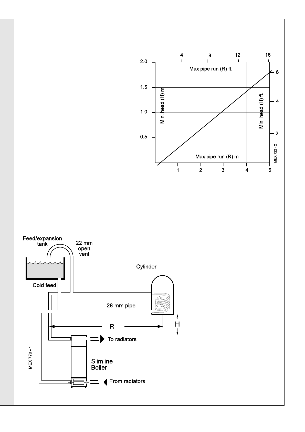
11
GRAVITY HOT WATER & PUMPED CENTRAL HEATING
1. Separate flow and return connections are used for
each service. All possible configurations are given
in Frame 1 but ONLY those shown should be
used.
2. The use of a cylinder thermostat is recommended.
This will prevent excessive DHW temperatures
and thus reduce gas consumption.
3. The schematic pipework graph is based on the
assumption that NO MORE than 8 elbows are
used in the gravity loop, including entry to the
boiler.
INSTALLATION
4. For each extra elbow in excess of 8, (R) MUST be
reduced by 300 mm (12") or (H) increased by 100
mm (4")
5. Whatever value is selected for (R) the value of (H)
MUST be at least that indicated by the graph.
INSTALLATLON
R = the horizontal distance between the centre line of
the cylinder and the boiler tappings used
(measured along the pipe run).
H = the vertical distance between the top of the boiler
and the base of the cylinder.
Notes.
a. Flow and return pipes should rise
vertically on leaving the boiler.
b. Horizontal pipes should be ABOVE
ceiling level and as short as possible.
c. A MINIMUM inclination of 25 mm per
3 m run (1" per 10') is required to
avoid air locks.
14
If the above conditions cannot be met
pumped primaries should be used.
Mexico Slimline CF 3/40 & 3/50 - Installation
Page 15

12
FLUE CONNECTION
Connect the flue pipe to the flue outlet.
The flue pipe spigot and socket connections
should be sealed with fibreglass rope or
similar, and suitable fireclay cement.
Notes.
a. The boiler flue connection outlet size is
suitable for flue pipe conforming to BS
567.
INSTALLATION
If sheet steel flue pipe is fitted, a suitable
adaptor must be used.
b. To facilitate installation and subsequent
disconnection it is recommended that a
slip or split socket be included in the flue
installation, adjacent to the boiler flue
outlet connection.
c. A minimum of 600mm (2') of vertical flue
directly above the boiler should be
provided.
13
ELECTRICAL CONNECTIONS
WARNING
The appliance MUST be efficiently earthed.
A mains supply of 230 V ~ 50 Hz is required.
All external controls and wiring MUST be suitable for mains
voltage.
Wiring should be in 3-core PVC insulated cable NOT LESS
than 0.75 mm
2
(24 x 0.2 mm) to BS.6500, Table 16.
INSTALLATION
Wiring external to the boiler MUST be in accordance with
current l.E.E. (BS 7671) Wiring Regulations and local
regulations.
Connection must be made in a way that allows complete
isolation of the electrical supply - such as a double pole
switch, having a 3mm (1/8") contact separation in both poles,
or a plug and socket serving only the boiler and system
controls. The means of isolation must be accessible to the
user after installation.
The fuse rating should be 3A.
14
INTERNAL WIRING
Flow and pictorial wiring diagrams are shown
in Frames 15 and 16. A schematic wiring
diagram is included in the Lighting Instruction
label.
1. Remove the securing screw and lift off the
control box cover.
2. Route the electrical leads into the box and
wire into the terminal strip, as shown.
Notes.
a. Secure each lead with one of the cable
clamps.
b. The mains lead connection MUST be
made so that, should the lead slip from its
anchorage, the current conductors
become taut before the earthing
conductor.
Mexico Slimline CF 3/40 & 3/50 - Installation
15
Page 16

INSTALLATION
15
EXTERNAL CONTROLS
External wiring must be in accordance with the
current I.E.E. (BS.7671) Wiring Regulations.
The wiring diagrams illustrated in Frames 1719 cover the systems most likely to be fitted to
this appliance.
For wiring external controls to the Mexico
Slimline 3 CF boiler reference should be
made to the system wiring diagrams supplied
by the relevant manufacturer, in conjunction
with the flow wiring diagram and also Frame
16.
INSTALLATION
Difficulty in wiring should not arise, providing
the following directions are observed:
1. Controls that switch the system ON and
OFF, e.g. a time switch, MUST be wired, in
series, in the live mains lead to the boiler.
2. Controls that override an ON/OFF control,
e.g. a frost thermostat, MUST be wired into
the mains lead, in parallel, with the control(s) to be
overridden. Refer to Frame 20.
3. Controls that switch the circulating pump only on and off
(e.g. a room thermostat) MUST be wired in series, with the
pump in the live pump lead.
4. If a proprietary system is used, follow the instructions
supplied by the manufacturer.
Advice on required modifications to the wiring may be
obtained from the component manufacturers.
Note. If there are no external controls the circulating pump
MUST be wired into the control box.
16
PICTORIAL WIRING
LEGEND
b blue
bk black
br brown
y/g yellow/green
16
Mexico Slimline CF 3/40 & 3/50 - Installation
Page 17

17
FULLY PUMPED - Y PLAN
Notes.
1. Some earth wires are omitted for clarity.
Ensure proper earth continuity when wiring.
2. Numbering of terminals on thermostats is
specific to the manufacturer indicated.
3. This is a fully controlled system - set the
boiler thermostat to maximum.
4. 'Switchmaster Midi' is similar in operation
but the wiring differs slightly; see
manufacturer's literature.
LEGEND
INSTALLATION
INSTALLATION
b blue
bk black
br brown
r red
18
FULLY PUMPED - S PLAN
Notes.
1. Some earth wires are omitted for clarity.
Ensure proper earth continuity when
wiring.
2. Numbering of terminals on thermostats
is specific to the manufacturer.
3. This is a fully controlled system - set the
boiler thermostat to maximum.
4. 'Switchmaster Autozone' has grey and
orange auxiliary switch leads but the
GREY (NOT the orange) wire must be
connected to the incoming live supply.
or orange
w white
gy grey
y/g yellow/green
LEGEND
b blue
bk black
or orange
br brown
r red
w white
y/g yellow/green
gy grey
Mexico Slimline CF 3/40 & 3/50 - Installation
17
Page 18

19
HONEYWELL 'C' PLAN
Gravity HW & Pumped CH
Notes.
1. Some earth wires are omitted for
clarity. Ensure proper earth
continuity when wiring
2. Numbering of terminals on
thermostats is specific to the
manufacturer.
INSTALLATION
INSTALLATION
LEGEND
w white
r red
20
FROST PROTECTION
Central heating systems fitted wholly inside
the house do not normally require frost
protection as the house acts as a 'storage
heater' and can normally be left at least 24
hrs. without frost damage. However, if parts
of the pipework run outside the house or if
the boiler will be left off for more than a day
or so then a frost 'stat should be wired into
the system.
This is usually done at the programmer, in
which case the programme selector
switches are set to OFF and all other
controls MUST be left in the running
position.
bk black
br brown
or orange
b blue
gy grey
g/y green/yellow
The frost 'stat should be sited in a cold place
but where it can sense heat from the
system.
Wiring should be as shown, with minimal
disturbance to other wiring of the
programmer.
Designation of the terminals will vary, but the
programmer and thermostat manufacturer's
leaflets will give full details.
18
Diagram A shows a double pole frost thermostat, which should suffice for all
systems which do not use the OFF terminals of the programmer.
Diagram B shows a 'change-over' frost thermostat, which will cover most
systems which do use CH OFF. If, however, on such a system the HW
pipework is in an isolated part of the house, a second frost thermostat may
be used to protect it.
If in doubt, ask your installer for advice.
Mexico Slimline CF 3/40 & 3/50 - Installation
Page 19

21
FITTING THE CASING
1. Offer up the LH side panel and secure
the panel to the baseplate and collector
hood.
2. Repeat step 1 to refit the RH side panel.
3. Place the top panel on top of the side
panels.
4. Secure the top panel to the side panels.
INSTALLATION
IMPORTANT.
Wiring within the boiler casing must be
neatly secured with the cable straps
provided and MUST NOT be allowed to
touch the burner front plate, or the cleanout
cover and the collector hood.
INSTALLATION
5. Insert the thermostat phial into the thermostat
pocket. Take care not to kink the thermostat
capillary as it is unwound, and secure it with the
split pin as shown.
6. Replace the control box cover and refit the control
panel using the screws previously removed.
7. Refit the grille assembly.
22
COMMISSIONING AND TESTING
A. ELECTRICAL INSTALLATION
1. Checks to ensure electrical
safety should be carried out by
a competent person.
2. ALWAYS carry out preliminary
electrical system checks, i.e.
earth continuity, polarity,
resistance to earth and short
circuit using a suitable test
meter.
B. GAS INSTALLATION
1. The whole of the gas installation, including
the meter, MUST be inspected and tested
for soundness, and purged in accordance
with the recommendations of BS. 6891.
2. Purging air from the gas installation may
be expedited by loosening the union on
the gas service cock on the boiler and
purging until gas is detected.
3. Retighten the union and check for gas
soundness.
WARNING. Whilst effecting the required gas soundness test and purging air from the
gas installation, open all windows and doors, extinguish naked lights and DO NOT
Mexico Slimline CF 3/40 & 3/50 - Installation
C. WATER CIRCULATING
SYSTEM
1. The whole of the system
should be thoroughly flushed
out with cold water WITHOUT
the pump in position. Ensure
that all valves are open.
2. With the pump fitted the
system should be filled and air
locks cleared. Check for
water soundness.
SMOKE.
19
Page 20

23
INSTALLATION
INSTALLATION
INITIAL LIGHTING
LEGEND
A Gas control knob
B Burner pressure test point
C Main burner pressure adjuster
D Inlet pressure test point
E Gas service cock
F Sightglass
G Piezo unit ignition
H Boiler thermostat knob
J Overheat thermostat
(optional) reset button.
1. Connect the gas valve electrical leads and refit the cover.
2. Check that the gas service cock (E) is ON and that the
boiler thermostat control knob (H) is OFF.
3. Loosen the screw in the burner pressure test point (B) and
connect a gas pressure gauge via a flexible tube.
4. Turn the gas control knob (A) CLOCKWISE until resistance
is felt and then release it.
5. Push in and retain fully depressed the gas control knob (A).
Press and release the piezo unit button (G) repeatedly until
the pilot is seen to light through the sightglass (F).
6. Hold the gas control knob (A) depressed for 15 seconds
after the pilot burner has ignited, then release.
If the pilot burner fails to remain alight at this stage, repeat
the procedure detailed above but wait longer than 15
seconds before releasing the gas control knob (A).
7. Check the appearance of the pilot flame to ensure that it
envelops the tip of the thermocouple and is approximately
25mm (1") long.
The pilot flame is factory set and no adjustment is possible.
9. Test for gas soundness around the boiler gas component
joints, using leak detection fluid.
10. Operate the boiler for 10 minutes to stabilise the burner
temperature. The boiler is pre-set at the factory to its
maximum nominal rating but can be range-rated to suit
the system design requirements. Refer to Table 2, page
3.
If the burner setting pressure requires adjustment,
remove the silver threaded protection cap on the top of
the regulator. Adjust the main burner pressure adjuster
(C) until the required main burner pressure is achieved.
Note. Continual adjustment in either direction will
produce the opposite effect.
11. If the boiler output is set to MID or MINIMUM affix the
appropriate indicator label, supplied, to the data plate
(front of baseplate).
12. Immediately check that there is no spillage of combustion
products from the draught diverter outlets by carrying out
a spillage test as detailed in BS. 5440:1.
Note. This must be done before any building in.
13. Turn the boiler thermostat knob (H) to OFF.
8. Switch the boiler thermostat control knob (H ) to position 6
and check that the burner cross-lights smoothly from the
pilot flame.
20
14. Remove the pressure gauge and tube. Retighten the
screw in the pressure test point, ensuring that a gas-tight
seal is made.
Mexico Slimline CF 3/40 & 3/50 - Installation
Page 21
INSTALLATION
24
GENERAL CHECKS
Make the following checks for correct operation:
1. Turn the boiler thermostat OFF and ON to check that the
main burner is extinguished and relit in response.
2. Check that the programmer, if fitted, and all other system
controls function correctly.
Operate each control separately and check that the main
burner or circulating pump (as the case may be) responds.
3. Flame failure device
The flame failure device must cut off the gas to the burner
within 60 seconds. Check the operation of the flame failure
device in the gas control valve as follows:
a. With the burner alight, turn the gas control knob
clockwise until resistance is felt and then release it. The
burner and pilot flame should shut down immediately.
Note. A latch in the gas control valve provides a safety
delay period of approximately 30 seconds before the
pilot can be relit.
b. The correct operation of external system controls should
be proved. Turn each, in turn, to OFF and ON and
check that the main burner or circulating pump
responds.
4. Water Circulation System
a. With the system HOT, examine all water connections
for soundness.
b. With the system still hot, turn off the gas, water and
electricity supplies to the boiler and drain down, in
order to complete the flushing process.
c. Refill and vent the system, clear all air locks and again
check for water soundness.
d. Balance the system.
5. Finally, set the controls to the user's requirements and refit
the lower panel and close the controls door.
Notes.
a. If an optional programmer kit is fitted refer to the separate
Programmer Kit Installation Instructions and User's
Instructions.
b. The temperatures quoted below are approximate and
vary between installations.
Thermostat Flow Temperature
Knob Setting
1 54 130
2 60 140
3 66 150
4 71 160
5 77 170
6 82 180
0
C
0
F
INSTALLATION
25
HANDING OVER
After completing the installation and commissioning of the system the installer should
hand over to the householder by the following actions:
1. Hand the User's Instructions to the householder and
explain his or her responsibilities under the Gas Safety
(Installation and Use) Regulations 1994, amendments 1996
or rules in force.
2. Draw attention to the lighting instruction label affixed to the
inside of the controls door.
3. Explain and demonstrate the lighting and shutting down
procedures including the function of the TTB downdraught
thermostat.
4. The operation of the boiler and the use and adjustment of
ALL system controls should be fully explained to the
householder, to ensure the greatest possible fuel economy
consistent with household requirements of both heating
and hot water consumption.
Advise the User of the precautions necessary to prevent
damage to the system and to the building, in the event of
the system remaining inoperative during frosty conditions.
5. Explain the function and the use of the boiler thermostat
and external controls.
6. Explain and demonstrate the function of time and
temperature controls, radiator valves etc., for the
economic use of the system.
7. If an optional Programmer Kit is fitted then draw attention
to the Programmer Kit User's Instructions and hand them
to the householder.
8. After installation, commissioning and customer hand-
over instructions please complete the
appliance log book and leave this with the customer.
9. Stress the importance of regular servicing by a CORGI
registered installer and that a comprehensive service
should be carried out AT LEAST ONCE A YEAR.
Mexico Slimline CF 3/40 & 3/50 - Installation
21
Page 22

26
SCHEDULE
SERVICING
e. Check the condition of the thermocouple.
To ensure the continued safe and efficient operation of the
appliance, it is recommended that it is checked at regular
intervals and serviced as necessary. The frequency of servicing
will depend upon the installation condition and usage but
should be carried out at least annually .
It is the law that any service work must be carried out by a
CORGI registered installer.
a. Light the boiler and carry out a pre-service check, noting
any operational faults.
b. Clean the main burner.
c. Clean the heat exchanger.
d. Clean the main injectors.
27
BOILER CASING REMOVAL
f. Check that the flue is unobstructed and that the flue
system, including the flue cleanout cover, is sealed
correctly.
g. If the appliance has been installed in a compartment,
check that the ventilation areas are clear.
The servicing procedures are covered more fully in Frames
28 to 32 and MUST be carried out in sequence.
WARNING. Always turn OFF the gas supply at the gas
service cock and switch OFF and DISCONNECT the
electrical supply to the appliance BEFORE SERVICING.
IMPORTANT. After completing the servicing or exchange of
components always test for gas soundness and carry out
functional checks as appropriate and test for spillage.
1. Lift off the lower front panel.
2. Remove the 2 screws and lift off the grille assembly.
3. Remove the gas valve electrical cover and
disconnect the electrical leads.
SERVICING
4. Release the gas valve lead from the retaining clip.
22
5. Remove the 2 screws securing the control panel
and pull down to release the tabs from under the
top panel.
6. Remove the thermostat phial from the pocket (as
shown) and unclip the TTB thermostat.
7. If the boiler is not fitted under a work top, access
for flue cleaning will be improved by removing the
top panel.
Mexico Slimline CF 3/40 & 3/50 - Installation
Page 23

28
BURNER AND CONTROLS ASSEMBLY
1. Lift off lower front panel (refer to Frame 27)
and remove the grille
assembly. Undo the
gas cock union
2. Undo the 2 wing nuts
and washers securing
the burner front plate
to remove the burner/
controls assembly
complete from the
boiler.
3. When replacing a
defective main burner
bar it is most
important that the
baffles are fitted to the
new burner.
29
CLEANING THE BURNER ASSEMBLY
SERVICING
Check that:
1. Remove the 2 split pins securing the burner end cap. The
cap, together with the circular gauze, can now be
removed from the burner bar. Clean the gauze to
remove any deposits of lint, fluff etc.
2. Brush off any deposits that may have fallen onto the
burner head, ensuring that the flame ports are
unobstructed, and remove any debris that may have
collected.
Note. Brushes with metallic bristles MUST NOT be used.
3. Remove the main burner injector. Check, clean or
replace, as required.
4. Refit the injector, using an approved jointing compound.
5. Inspect the pilot burner, thermocouple and ignition
electrode; ensure they are clear and in good condition.
30
CLEANING THE FLUEWAYS
1. Remove the burner assembly.
2. Remove the cleanout cover.
a. The pilot burner is clean and unobstructed.
b. The pilot shield is clean and unobstructed.
c. The ignition electrode is clean and undamaged.
d. The ignition lead is in good condition and securely
connected.
d. The spark gap is correct. Refer to Frame 39.
e. The thermocouple tip is not burned or cracked.
f. The position of the thermocouple relative to the pilot
burner is correct. Refer to Frame 39.
g. The thermocouple terminal at the gas valve is clean and
secure.
h. The sightglass is clean and undamaged.
6. Clean or renew components as necessary.
SERVICING
3. Lift out the flue baffle.
4. Remove all loose deposits from the heat
exchanger, especially from between the
fins, using a suitable brush. Remove all
debris from the combustion chamber base.
5. Check that the flue outlet duct is
unobstructed.
Mexico Slimline CF 3/40 & 3/50 - Installation
23
Page 24

31
RE-ASSEMBLY
Re-assemble the boiler in the following order :
SERVICING
1. Refit the flue baffle into the boiler flueway, ensuring that
they are correctly repositioned. Refer to Frame 6.
2. Refit the flue cleanout cover, renewing any damaged or
deteriorating sealing gasket.
3. Refit the casing top panel.
4. Reconnect the electrical wiring and refit the controls
panel, ensuring that the thermostat phial and phial
retaining clip are correctly located in the thermostat pocket
and secured by the split pin. Refer to Frame 27.
32
GAS PRESSURE ADJUSTMENT
1. Pilot pressure.
Pilot adjustment is factory set to maximum and no
adjustment is possible,
5. Check the sightglass in the front plate - clean or renew as
necessary.
6. Renew any damaged or deteriorating front plate gasket.
7. Refit the burner and controls assembly.
8. Reconnect the gas service cock.
9. Refit the grille assembly.
Any required adjustments should be made using the
pressure adjustment screw. Refer to Frame 23, 'Initial
Lighting'.
2. Main burner pressure.
After servicing, reference should be made to Table 2,
which quotes details of the rated output with the related
burner pressure and heat input.
SERVICING
Refit the lower front panel in reverse order. Refer to
Frame 27.
24
Mexico Slimline CF 3/40 & 3/50 - Installation
Page 25

33
GENERAL
SERVICING
REPLACEMENT OF PARTS
34
SIGHTGLASS REPLACEMENT
When replacing any component:
1. Isolate the electricity supply.
2. Turn off the gas supply at the boiler.
3. Remove the lower front panel.
For replacement of programmer units
refer to the separate Programmer Kit
Instructions.
35
PIEZO UNIT REPLACEMENT
1. Disconnect the ignition lead from the piezo
unit body.
2. Remove the 2 nuts securing the body to the
studs on the gas valve and withdraw the unit,
as shown.
1. Unfasten the two wing nuts and washers. Remove the assembly from the
front plate.
2. Fit the new
sightglass and reassemble in the
correct order (i.e.
gasket, glass,
gasket and frame),
as shown.
3. Retighten 2 wing
nuts to ensure an
airtight
seal. Do NOT
overtighten.
3. Fit the new unit and reassemble in reverse
order.
36
PILOT BURNER REPLACEMENT
1. Lift off lower front panel and remove the grille
assembly. Undo the gas cock union. Remove the
burner and controls assembly. Refer to Frames 27 &
28.
2. Remove the ignition electrode. Refer to Frame 41.
3. Unscrew the thermocouple nut and pull the
thermocouple clear.
4. Undo the pilot supply pipe nut and ease clear of the
pilot burner. DO NOT lose the pilot injector, which is a
push-fit in the pilot burner housing.
5. Remove the 2 securing screws and washers, and
withdraw the pilot burner.
6. Fit the new pilot burner and re-assemble in reverse
order, ensuring that:
SERVICING
a. The injector is in position when refitting the pilot
supply.
b. A gas-tight joint is made.
c. The spark gap is correct.
7. Refit the thermocouple and electrode, reassembling in reverse order.
Mexico Slimline CF 3/40 & 3/50 - Installation
25
Page 26

37
BOILER THERMOSTAT REPLACEMENT
SERVICING
1. Lift off the front lower panel - Refer to
Frame 27.
2. Pull off the thermostat knob.
3. Remove the 2 screws and pull down the
control panel tabs clear of the top panel.
4. Remove the thermostat phial from the
pocket - refer to Frame 27.
5. Remove the bottom self tapper and remove
the cover.
6. Remove the top self tapper and ease the
control box off the control panel.
7. Remove the 2 self tappers to release the
thermostat bracket.
8. Disconnect the electrical leads.
9. Unscrew the thermostat nut to withdraw the
thermostat.
38
CONTROLS PANEL REPLACEMENT
1. Lift off the lower front panel. Refer Frame 27
2. Pull off the thermostat knob.
3. Disconnect the electrical connections from
the gas valve.
SERVICING
4. Unscrew the 2 screws and pull down the
control panel so that the 2 tabs clear the top
panel.
5. Remove the bottom screw and remove the
cover from the control box.
6. Remove the top screw and ease the control
box off the control panel.
7. Disconnect the mains electrical supply from
the terminal strip and release from its clamp.
8. Remove the 2 screws to release the
thermostat bracket.
9. Disconnect the TTB thermostat leads from
the terminal strip and control thermostat.
Then release from its bush.
10. Remove the thermostat phial from the pocket.
Refer to Frame 27.
11. On the new control box gain access to the
control thermostat as described above.
12. Discard the control thermostat lead that connects
to terminal strip marked 'L
13. Reconnect the TTB thermostat lead to the control thermostat and
terminal strip marked 'L
14. Assemble new control box and panel and fit to the casing reverse order.
'.
G
'.
G
10. Fit the new thermostat and re-assemble in
reverse order.
26
Mexico Slimline CF 3/40 & 3/50 - Installation
Page 27

39
OVERHEAT THERMOSTAT REPLACEMENT
1. Lift off the lower front panel. Refer
to Frame 27.
2. Remove the 2 screws and pull
down the control panel tabs to
clear the top panel.
3. Remove the split pin at the
thermostat pocket and withdraw
the phials from the pocket.
4. Remove the thermostat backnut.
5. Remove the 2 Eco leads.
6. Fit the new thermostat (lead
polarity immaterial), ensuring that
the alignment peg on the
thermostat sits in the small hole
adjacent to the main fixing hole,
and reassemble in reverse order.
SERVICING
40
IGNITION LEAD REPLACEMENT
1. Lift off lower front panel and remove
the grille assembly. Undo the gas
cock union. Remove the burner and
controls assembly. Refer to Frames
27 & 28.
2. Remove the 2 wing nuts securing
the burner front plate. This complete
burner/controls assembly can now
be removed from the boiler.
3. The ignition lead can be removed by
disconnecting at the piezo unit and
the electrode.
4. Fit the new lead and re-assemble in
reverse order.
SERVICING
Mexico Slimline CF 3/40 & 3/50 - Installation
27
Page 28

41
IGNITION ELECTRODE REPLACEMENT
1. Lift off lower front panel and remove the
grille assembly. Undo the gas cock union.
Remove the burner and controls assembly.
Refer to Frames 27 & 28.
2. Pull off the ignition lead at the electrode.
The electrode is secured by a nut. Remove
the nut and withdraw the electrode upward.
Re-assemble in reverse order.
SERVICING
SERVICING
42
THERMOCOUPLE REPLACEMENT
1. Lift off lower front panel and remove the
grille assembly. Undo the gas cock
union. Remove the burner and controls
assembly. Refer to Frames 27 & 28.
2. Undo the thermocouple nut at the pilot
burner and connection at the gas valve
and pull the thermocouple clear.
3. Fit the new thermocouple.
Note. Avoid sharp bends in the
thermocouple lead and ensure that it
follows the same route as previously.
4. Re-assemble in reverse order.
28
Mexico Slimline CF 3/40 & 3/50 - Installation
Page 29

43
MAIN BURNER REPLACEMENT
SERVICING
1. Lift off lower front panel and remove the grille assembly.
Undo the gas cock union. Remove the burner and controls
assembly. Refer to Frames 27 & 28.
Undo the 2 wing nuts and remove the burner and controls
assembly.
2. Undo the nut securing the pilot bracket to the main burner
and remove the pilot bracket.
3. Remove the 4 nuts and washers securing the main burner to
the front plate and gas manifold. Withdraw the burner.
4. Remove the nut securing the burner baffle to the burner.
5. Fit the new burner and re-assemble in reverse order, taking
care not to damage the main burner injector which is
screwed into the end of the gas manifold.
44
MAIN BURNER INJECTOR REPLACEMENT
1. Lift off lower front panel and remove the
grille assembly. Undo the gas cock
union. Remove the burner and controls
assembly. Refer to Frames 27 & 28.
2. Unscrew the burner injector from the
manifold.
SERVICING
3. Fit the new injector, using an approved
jointing compound, and re-assemble in
reverse order.
Mexico Slimline CF 3/40 & 3/50 - Installation
29
Page 30

45
GAS VALVE REPLACEMENT
1. Lift off lower front panel and
remove the grille assembly.
Undo the gas cock union.
Remove the burner and
controls assembly. Refer to
Frames 27 & 28.
2. Undo the pilot pipe and
thermocouple connections at
the gas valve.
3. Unfasten the 4 screws
securing the gas inlet pipe to
the LH side of the gas valve.
4. Unfasten the 4 screws
securing the gas manifold.
The 2 sealing 'O' rings should
be discarded and new 'O' rings
fitted.
5. Fit the new gas valve, ensuring
that:
SERVICING
a. The valve is fitted the correct
way round - an arrow
engraved on the valve
indicates the direction of flow.
b. The sealing 'O' rings supplied with the valve are correctly
fitted at the inlet and outlet flanges.
6. Check the complete assembly for gas soundness.
46
TTB DOWNDRAUGHT THERMOSTAT REPLACEMENT
SERVICING
1. Remove the control panel. Refer to Frame
38.
2. Remove the securing screw and lift off the
control box cover.
3. Disconnect the TTB thermostat and remove
from the cable clamp and control box.
Refer to Frame 38.
Note.The TTB thermostat is located at the
LH side of the diverter panel.
4. Reach down the side of the boiler and
carefully lift the TTB bracket from its
retaining slot and clip.
5. Withdraw the thermostat, bracket and lead
down the side of the boiler.
6. Locate and fit the new TTB downdraught
thermostat, bracket and lead and reassemble in reverse order, ensuring that all
electrical connections are correctly remade
and cables secured.
30
Mexico Slimline CF 3/40 & 3/50 - Installation
Page 31

FAULT FINDING
Before attempting any electrical fault finding ALWAYS carry
out preliminary electrical system checks, i.e. earth continuity,
polarity and resistance to earth using a suitable meter.
47
PILOT WILL NOT LIGHT
Is there a spark at the ignition electrode ?
YES
Is there gas at the pilot burner when the gas valve
knob is pressed ?
YES
NO
NO
YES
Detailed instructions on the cleaning and adjustment
or replacement of faulty components are contained in
the 'Servicing' section of this publication.
Check that the gap between the electrode and the pilot
burner is 3-4 mm. Refer to Frame 36.
Check that the HT lead and electrode are undamaged and
the connections are NOT close to earthed metalwork.
Check the piezo unit is operative by holding an earthed
screwdriver approx. 3mm from the HT output terminal
(with the ignition lead removed) and by operating the
button.
Is there a spark across the gap ?
Does the pilot light when a match is applied ?
YES
Check that there is no blockage in the pilot line
or pilot injector.
Adjust the pilot to correct size (flame enveloping
approx. 13mm of the thermocouple tip).
Confirm satisfactory ignition using the piezo unit.
48
PILOT WILL NOT STAY LIT WHEN THE GAS CONTROL VALVE KNOB IS RELEASED
Does the overheat thermostat (if fitted) require resetting ?
NO
Is the connection between the thermocouple and
the gas control valve clean and tight ?
YES
Is the pilot flame correctly set to maximum ?
YES
Check the thermocouple output (6-10 mV closed circuit). Replace
thermocouple if output is outside the stated range. Reference may
be made to the British Gas Multimeter Instruction book
Does the pilot now stay alight ?
NO
Faulty
piezo
unit -
replace
YES
NO
Allow time to purge any air
present by increasing the pilot gas
rate (done by adjusting the
Check that the gas control knob is
being pressed fully in, that there
is gas pressure at the boiler inlet
and that the pilot jet is not
NO
screw).
blocked.
Does the pilot now stay alight ?
NO
Replace the overheat thermostat
Clean the contacts and reconnect securely
Replace the gas control valve
unit - replace
NO
NO
Faulty piezo
Replace the
gas control
valve
49
PILOT LIT BUT NO MAINS GAS
Is there a supply voltage at the input to the control box?
YES
Set any CH and HW controls to the 'Continuous'
position. Is there a supply voltage between CH and N,
also between HW and N? Expect 230 V +10% -6%
YES
Have you confirmed that the system controls
Is there a supply voltage between the gas control valve
Note. After any faults have been corrected, return all thermostatic and other controls to the previously noted settings
are 'Calling for Heat' ?
YES
terminals ? Expect 230 V +10% -6%
YES
Does the main burner light ?
Mexico Slimline CF 3/40 & 3/50 - Installation
NO
NO
NO
NO
NO
Check the supply voltage, e.g., by using a multimeter,
set on the 300V AC range, between the L and N
terminals. Expect 230V +10% -6%. If no supply,
check the fuse in the plug or other supply point.
If no supply, check the controls. Reference may be
made to the British Gas Multimeter Instruction Book.
Check the settings of the room thermostat and the
cylinder thermostat. Check the control system.
Reference may be made to the British Gas Multimeter
Instruction Book.
Check the boiler thermostat. Reference may be made
to the British Gas Multimeter Instruction Book. Check
the TTB downdraught thermostat. Is there a
downdraught in the flue?
Replace the gas control valve
FAULT FINDING
31
Page 32

SHORT LIST OF PARTS
The following are parts commonly required as replacement
components, due to damage or expendability. Their failure or
absence is likely to affect safety or performance of this appliance.
The list is extracted from the British Gas List of Parts, which
contains all available spare parts.
The full list is held by British Gas, Caradon Plumbing Limited
distributors and merchants.
Key No. G.C. Part No. Description Qty. Product No.
7 319 494 Sightglass assembly kit. 1 079 334
9 398 252 Main burner BRAY AB 16642 1 012 532
11 Main burner injector
398 323 BRAY Cat. 16 - size 1200: CF 3/40 1 002 608
398 055 BRAY Cat. 10 - size 1400: CF 3/50 1 003 361
12 341 957 Pilot burner HONEYWELL Q 359A 1041,
with injector Key No. 13 1 077 868
When ordering spares please quote:
1. Boiler model
2. Appliance G.C. number
3. Description
4. Quantity
5. Product no.
13 381 656 Pilot burner injector: HONEYWELL 45004-108-001 1 003 825
15 E01 507 Gas valve assy. (V4600A1130 - 230V) 1 079 756
17 395 705 Piezo unit - MORGAN / MATROC 60080 002. 1 003 939
18 388 396 Ignition electrode - MORGAN / MATROC 1 003 038
19 E01 412
20 390 039 Thermocouple - HONEYWELL Q 309 A 2739, 600mm lg. 1 000 842
25 Thermostat - RANCO K36-P1354 1 151 903
26 308 557 Thermostat knob 1 111 904
41 E01 415 Flue baffle CF 3/40 1 150 989
E01 416 Flue baffle CF 3/50 1 150 938
42 Downdraught thermostat (TTB) 1 075 372
HT lead 460mm long 1 052 888
32
Mexico Slimline CF 3/40 & 3/50 - Installation
Page 33

50
SHORT PARTS
LIST OF PARTS
Mexico Slimline CF 3/40 & 3/50 - Installation
33
Page 34

LIST OF PARTS
51
BURNER AND CONTROLS ASSEMBLY - Exploded View
Legend
6. Front plate assembly
7. Sightglass assembly.
8. Pilot pipe.
9. Main burner.
11. Main burner injector.
12. Pilot burner.
14. Pilot burner bracket assy.
15. Gas valve.
34
16. 'O' ring.
17. Piezo unit.
18. Ignition electrode.
19. Ignition (HT) lead.
20. Thermocouple.
21. Gas cock.
43. Outlet pipe.
44. Inlet pipe.
Mexico Slimline CF 3/40 & 3/50 - Installation
Page 35

LIST OF PARTS
52
CONTROL BOX ASSEMBLY - Exploded View
Legend
23. Control panel complete.
24. Control box.
25. Control thermostat.
26. Thermostat knob.
27. Controls panel.
28. Magnetic strip.
29. Controls front panel.
Mexico Slimline CF 3/40 & 3/50 - Installation
35
Page 36

53
BOILER CASING ASSEMBLY
LIST OF PARTS
36
Legend
22. Casing complete.
23. Control panel complete.
32. L.H. side panel.
33. R.H. side panel.
34. Top panel.
35. Grille panel.
36. Front lower panel.
37. Top panel infill piece.
Mexico Slimline CF 3/40 & 3/50 - Installation
Page 37

Mexico Slimline CF 3/40 & 3/50 - Installation
37
Page 38

THIS SYMBOL IS YOUR
ASSURANCE OF QUALITY
The code of practice for the installation,
commissioning & servicing of central heating systems
These appliances are designed for use with Natural
Gas only. They have been tested and conform with
the provisions of BS. 6332 and BS. 5258.
Caradon Plumbing Limited, P.O. Box 103, National Ave, Kingston upon Hull, HU5 4JN.
Telephone: 01482 492 251 Fax: 01482 448 858. Registration No. London 322 137. Registered
Office: National Avenue, Kingston upon Hull, HU5 4JN. A subsidiary of Caradon p.l.c
Technical Training
The Caradon Plumbing Limited Technical Training Centre
offers a series of first class training courses for domestic,
commercial and industrial heating installers, engineers and
system specifiers.
For details of courses please ring: .............. 01270 413 624
Ideal Installer/Technical Helpline
CERTIFIED PRODUCT
Manufactured under a BS EN ISO 9001: 1994
Quality System accepted by BSI
Caradon Plumbing Limited
pursues a policy of continuing
improvement in the design and
performance of its products. The
right is therefore reserved to vary
specification without notice.
September 1999 151 905 A04
Tel: 01482 498 663
38
Mexico Slimline CF 3/40 & 3/50 - Installation
Page 39
Your feedback
and your chance to win a free boiler
At Ideal we've been leaders in the design and engineering of robust and
reliable boilers for over 90 years. We want to continue as leaders by
listening to your suggestions for how to improve our boilers and our service.
We'll be giving away a free boiler for the five best ideas every year (to be
selected by our Technical Director). Please complete this form, using
extra sheets if required, and post it or fax it to us on 01482 498699.
Boiler details
Model / Size (e.g. Classic RS 230, Mexico CF 3/60 etc. Details on control panel door)
Date of Installation
Installer details
Name
Address
Post Code Telephone (Please include STD code)
How I would improve this boiler:
My general comments for Ideal:
:
Ideal Installer/Technical Helpline
Mexico Slimline CF 3/40 & 3/50 - Installation
Tel: 01482 498 663
39
Page 40

Further information
If you would like information about Ideal Boilers please complete this
sheet and fax it to us on 01482 498699 or post it to Caradon Plumbing
Limited, PO Box 103, National Avenue, Kingston upon Hull, HU5 4JN.
Installer details
Name
Address
Post Code Telephone (Please include STD code)
General information required
Please send me details of Ideal Training Courses.
Please arrange for a technical representative to contact me.
Please arrange for me to join an Ideal factory tour.
Range guides required
The Ideal Guide: a specifier's and installer's introduction to the
Ideal domestic boiler range.
The Ideal Householders Guide: to assist the installer when
presenting to his/her customers.
Technical manuals required
The Ideal C class combi boiler
The Ideal Classic wall hung boiler
The Ideal Classic System wall hung boiler
The Ideal Classic LX Deluxe wall hung boiler
The Ideal Mexico floor standing boiler
The Ideal Minimiser heat-saving boiler
The Ideal Response combi boiler
The Ideal Response SE super efficiency combi boiler
The Ideal Systemiser SE super efficiency system boiler
The Ideal Concord high output boiler
The Ideal Buccaneer oil fired boiler
Caradon Plumbing Limited, PO Box 103, National Avenue, Kingston upon Hull, HU5 4JN. Telephone: 01482 492251 Fax: 01482 448858.
Ideal Installer/Technical Helpline
Tel: 01482 498 663
U.I.N. 151 905 A0
 Loading...