

Page 1
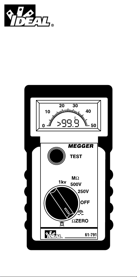
#61-791
MEGGER
®
Hand-held Insulation & Continuity Tester
Probadores manuales de aislamiento y continuidad
Appareil de poche pour la mesure de l'isolement et
l'essai de la continuité
Page 2
SAFETY WARNINGS
✱ Safety warnings and precautions must be read and
understood
before the instrument is used. They must be
observed during use.
✱ The circuit under test must be switched off, de -
energised and isolated
before Insulation or Continuity
tests are made.
✱ The test button must not be held down while connecting
the test leads or while changing ranges. (May cause
‘Live Circuit Warning‘ to become inoperable).
✱ The Voltage warning does not function if OFF or
is selected.
✱ During an insulation test, connections must not be
touched.
✱ After insulation tests, capacitive circuits must be allowed
to discharge
before disconnecting the test leads.
✱ Test leads, prods and crocodile clips must be in good
order; clean, and with no broken or cracked insulation.
✱ Replacement fuses must be of the correct size, type and
rating.
NOTE
THE INSTRUMENTS MUST ONLY BE USED BY SUITABLY TRAINED AND COMPETENT
PERSONS.
Symbols used on the instrument:
Caution: risk of electric shock
Caution: refer to accompanying notes
Equipment protected throughout by Double Insulation (Class
II)
Equipment complies with relevant EU Directives
Page 3
The 61-791 has the following features:
✷ 1mA Insulation test current
✷ 200mA Continuity test with lead zeroing facility
✷ Combined curved Analogue / Digital display
✷ Continuity Beeper
✷ Auto shut off
✷ Display Back light
✷ Low Battery indication
✷ 250 Volt Insulation
✷ 500 Volt
✷ 1000 Volt Insulation
✷ Default Voltmeter
OPERATION
Preliminary Test lead check
1. Before each use of the instrument, visually inspect the test leads, prods
and crocodile clips to confirm that their condition is good, with no damaged
or broken insulation.
2. Check continuity of the test leads by firmly shorting the leads together
and read the test lead resistance. measurement directly from the display.
Backlight operation
1. Turn the instrument backlight ‘On’by selecting the position.
2. When the backlight is activated, select the desired test position.
3. On completion, select the ‘
OFF’ position to de-activate the backlight and
conserve battery life.
Continuity Testing
1. Turn the instrument ‘On’by selecting the Ω range.
2. If required, zero test lead resistance by firmly shorting both leads together,
wait for the reading to stabilise and press the test button. Display of the
symbol confirms lead zeroing.
Note: Lead zeroing cancels each time
the instrument is switched off, or
Auto shut off operates.
3. Connect the test probes to the isolated circuit under test.
4. The display shows the resistance value. (Maximum 99,9Ω)
5. On completion switch to ‘
OFF’ position. Alternatively auto shut off operates
after 5 minutes of instrument inactivity.
Continuity Beeper On the position, a continuous beep note
sounds when the test leads make contact with resistance less than 5Ω. Ιf
contact is maintained, beeping ceases after a few seconds and the resistance
value is displayed. Resistance greater than 5
Ω is indicated by an intermittent
beep note.
Leads
Nulled
Low Battery
Fuse
Ruptured
Refer to Safety Warnings before using the instrument
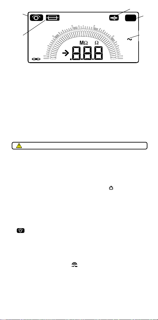
DISPLAYFEATURES
High
Voltage
Default
Voltage
100
1 G
200
100 M
300
10 M
1000V
400
1 M
V
0
100k
500
Page 4
Insulation Testing
1. Turn the instrument ‘On‘ by selecting the MΩ range.
2. Connect the test probes to the isolated circuit under test.
3. Press and hold the push button; the display shows the insulation value.The
reading will remain displayed for a few seconds after the push button is
released. As an additional safety feature, instruments with
1000V range will
flash symbol before performing a test.
4. Release the push button before removing the test leads (to enable the
instrument to discharge the circuit under test).
5. On completion switch to the ‘
OFF’ position. Alternatively auto shut off
operates after 12 minutes of inactivity.
SPECIFICATION
Insulation
Test VoltageAccuracy: -0% + 30% (over full operating temperature)
into 0 to 1mA load
Measuring Range: 0,01MΩ - 999MΩ (Digital)
0,1MΩ - ∞ (Analogue)
Short Cct. Current: Less than 2mA
Accuracy (at 20°C): ± 3% ±2 digits up to 10MΩ
± 5% ±2 digits up to 100MΩ
± 30% up to 999MΩ
Output Noise Voltage: Typically 2V pk to pk at 20kHz (at 1mAload)
Hum Rejection: <10% error with 100µA RMS (0,2MΩ to ∞)
Continuity
Measuring Range: 0,01Ω - 99,9Ω
Open Cct. Voltage: 5V ±1V
Accuracy (at 20°C): 0,01Ω - 9,99Ω ±3% ± 2 digits (ISC>200mA)
10
Ω − 100Ω ± 5% ± 2 digits (ISC>20mA)
Lead res. comp: 0 to 9,99Ω
Hum Rejection: <3% error with 1V RMS (0,2Ω to 50Ω)
Continuity Beeper: On position, the beeper sounds at <5Ω resistance
Environmental Conditions
Temperature Coefficient:<0,1% per °C
Temperature Range:
Operating: -20°C to +40°C (full measurement range)
-20°C to +60°C (to 100 MΩ maximum)
Storage: -25°C to +65°C
Humidity: 90% RH at 40°C max
General Specifications
Display: 3 digit L.C.D. Maximum reading 999
Auto Shut off: Operates after 5 minutes of inactivity by the
instrument in Continuity position and 12 minutes in Insulation position. Beep
notes pre-empt auto shut off. The instrument can be switched back on by
pressing the test button, or by selecting ‘
OFF‘ and then the required position.
Default Live Circuit Warning
When more than 25 V is applied to the terminals, the instruments default to a
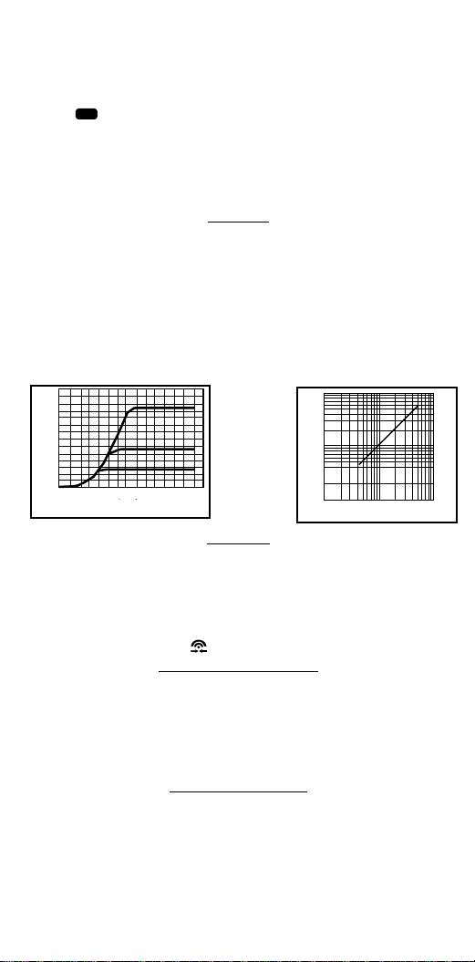
Terminal Characteristics
Limiting Value
1000V
1300
1200
1100
1000
900
800
700
600
500
400
300
200
Terminal Voltage
100
0,1MΩ
0,01MΩ
0.5MΩ
1,0MΩ
Load
1000 V Range
500 V Range
250 V Range
10MΩ
100MΩ
10MΩ
5MΩ
2MΩ
1MΩ
0,5MΩ
Minimum Indicated Value
0,2MΩ
0,2MΩ
0,5MΩ 1MΩ
2MΩ
5MΩ
Page 5

voltmeter on all switch positions except ‘OFF’ and . In addition, the beeper
will sound on all switch positions except ‘
OFF‘ and . All selected tests will be
inhibited except for Insulation tests, which will remain available until the voltage
exceeds 55 V.
Default Voltmeter Ranges: 25V - 450V a.c. 50/60 Hz ± 2% ±3 digits
450V - 600V a.c. 50/60 Hz ± 3%
d.c. - unspecified
Automatic Discharge: Capacitive circuits are automatically discharged
when the test button is released following an insulation test.
Power Supply: 6 x 1,5V cells IEC LR6 type only.
Battery life: Typically 3000 x 5 second operations (worst
case, with not
selected).
Battery cells should not be left in an instrument which may remain unused for
extended periods of time.
Low Battery Indicator: The low battery indicator symbol will appear
when the battery cells are exhausted.
Battery Replacement: The rear cover must not be opened if the test
leads are connected. To remove the rear cover, release the screw at the
bottom of the cover and lift the cover upwards.To avoid the possibility of
shock,
do not press the test button or touch the fuse when changing
batteries.
Fuse: 500 mA (F) H.B.C.10 kA min (32mm x 6mm)
To check this fuse, select
MΩ, open circuit the test leads and press the test
button until a reading is obtained. Display of the fuse symbol or an error
code indicates a ruptured fuse. Located behind the rear cover, this fuse can
be replaced by the user. The rear cover
must not be opened if test leads are
connected. The replacement fuse
must be of the correct type and rating. To
avoid the possibility of shock, disconnect the battery
before touching the fuse.
Safety: The instruments meet the requirements for double insulation to IEC
1010-1 (1995) EN 61010-1 (1995) to Category
III*, 300 Volts phase to earth,
440 Volts phase to phase, without the need for separately fused test leads.
*Relates to transient overvoltage likely to be found in fixed installation wiring.
E.M.C. Meets EN 50081-1 and EN 50082-1 (1992).
Weight: 530g (including batteries)
Dimensions: 195mm x 98mm x 40mm.
Cleaning: Wipe disconnected instrument with a clean cloth
dampened with soapy water or Isopropyl Alcohol
(IPA).
ACCESSORIES
Supplied Part Number
Synthetic zip-up pouch C90
Test leads, prods & crocodile clips TL - 791
Page 6

Lifetime Limited Warranty
This meter is warranted to the original purchaser against defects in material or
workmanship for the lifetime of the meter. During this warranty period, IDEAL
INDUSTRIES, INC. will, at its option, replace or repair the defective unit,
subject to verification of the defect or malfunction.
This warranty does not apply to defects resulting from abuse, neglect,
accident, unauthorized repair, alteration, or unreasonable use of the
instrument.
Any implied warranties arising out of the sale of an IDEAL product, including
but not limited to implied warranties of merchantability and fitness for a
particular purpose, are limited to the above. The manufacturer shall not be
liable for loss of use of the instrument or other incidental or consequential
damages, expenses, or economic loss, or for any claim or claims for such
damage, expenses or economic loss.
State laws vary, so the above limitations or exclusions may not apply to you.
This warranty gives you specific legal rights, and you may also have other
rights which vary from state to state.
IDEAL INDUSTRIES, INC.
Sycamore, IL 60178, U.S.A.
800-304-3578 Customer Assistance
www.idealindustries.com
ND 3357-1
Part No. 6172 - 727
Page 7

REMARQUE
l’UTILISATION DE CES INSTRUMENTS DOIT ETRE RESERVEE A UN PERSONNEL FORME ET COMPETENT.
Symboles utilisés sur l'instrument
Risque de choc électrique
Consulter le Guide de l'utilisateur
Équipement entièrement protégé par un isolement
double (Classe
II).
Équipement conforme aux Directives en vigueur de l'UE
.
Mode D’Emploi
Vérification préliminaire des câbles d’essai
1. Avant chaque utilisation de l’instrument, inspecter visuellement les câbles d’essai,
les sondes et les pinces crocodiles pour confirmer qu’ils sont en bon état, et que leur
isolement n’est pas cassé ou fissuré.
2. Vérifier la continuité des câbles d’essai en court-circuitant fermement les câbles et
en lisant leur mesure de résistance directement sur l’affichage.
Rétro-éclairage
1. Mettre le rétro-éclairage de l’instrument en service “ON” en sélectionnant la position .
2. Lorsque le rétro-éclairage est activé, sélectionner la position d’essai requise.
3. A la fin de l’essai, sélectionner la position “
OFF” pour désactiver le rétro-éclairage et
conserver les piles.
Essai de continuité
1. Mettre l’instrument en service “ON” en sélectionnant la gamme Ω.
2. Si nécessaire, mettre à zéro la résistance des câbles d’essai en court-circuitant
fermement les câbles, attendre que la lecture se stabilise et presser le bouton
d’essai. L’affichage du symbole confirme la mise à zéro.
Nota: La mise à zéro des câbles est annulée à chaque fois que l’instrument est arrêté
ou que la fonction Arrêt automatique est activée.
3. Brancher les sondes d’essai sur le circuit isolé à tester.
4. L’affichage indique la valeur de la résistance. (Maximum 99,9 Ω).
5. A la fin de l’essai, sélectionner la position “
OFF”. Sinon, la fonction d’arrêt
automatique sera activée après 5 minutes d’inactivité de l’instrument.
Avertisseur de continuité - Sur la position , un tonalité continue est émise lorsque les
câbles d’essai sont en contact avec des résistances inférieures à 5 Ω. Si le contact est
AVERTISSMENTS RELATIFS A LA SECURITE
•
Le circuit à tester doit être coupé, désexcité et isolé avant d’entreprendre
les essais d’isolement ou de continuité.
• Le bouton d’essai ne doit pas être pressé pendant le branchement des
câbles d’essai.
• Le voyant Voltage ne fonctionne pas si OFF ou est sélectionné.
• Pendant un essai d’isolement, le circuit ne doit pas être touché.
• Après les essais d’isolement, laisser décharger les circuits capacitifs avant
de débrancher les câbles d’essai.
• Les câbles d’essai, les sondes et les pinces crocodiles doivent être en bon
état, propres et avec un isolement sans cassures ni fissures.
• Les fusibles de rechange doivent être de la dimension, du type et de la
puissance nominale corrects.
• Les avertissements et précautions de sécurité doivent être lus et compris
avant d’utiliser l’instrument. Ils doivent être observés pendant l’usage.
Consulter les avertissements relatifs à
la sécurité avant d’utiliser l’instrument
Page 8

maintenu, la tonalité cesse après quelques secondes et la valeur de la résistance est
affichée. Les résistances supérieures à 5Ω sont signalées par une tonalité intermittente.
Essai d’isolement
1. Mettre l’instrument en service “ON” en sélectionnant la gamme MΩ.
2. Brancher les sondes d’essai sur le circuit isolé à tester.
3. Presser et tenir appuyé le bouton d’essai; l’affichage indique la valeur de l’isolement.
La lecture restera affichée pendant quelques secondes après le relâchement du
bouton d’essai. En sécurité supplémentaire sur les instruments ayant une gamme de
1000V, le symbole clignotera avant d’effectuer un essai.
4. Relâcher le bouton poussoir avant de débrancher les câbles d’essai (pour permettre
à l’instrument de décharger le circuit testé).
5. A la fin de l’essai, sélectionner la position “
OFF”. Sinon, la fonction d’arrêt
automatique sera activée après 12 minutes d’inactivité de l’instrument.
Spécifications Générales
Affichage: LCD, 3 chiffres. Lecture maximum 999.
Arrêt automatique: Fonctionne après 5 minutes d’inactivité en position Continuité, ou 12
minutes en position Isolement. Une tonalité précède l’arrêt automatique. L’instrument peut
être remis en marche en appuyant sur le bouton d’essai, ou en sélectionnant “Off” puis la
position requise.
Avertissement par défaut de circuit sous tension:
Lorsqu’une tension supérieure à 25V est appliquée aux bornes, l’instrument se transforme
par défaut en voltmètre pour toutes les positions à l’exception de “OFF” et . En outre,
l’avertisseur retentit pour toutes les positions à l’exception de “OFF” et . Tous les essais
sélectionnés seront inhibés à l’exception des essais d’isolement, qui resteront disponibles
jusqu’à ce que la tension dépasse 55V.
Gammes de voltmètre par défaut: 25V - 450V c.a. 50/60 Hz ±2% ±3 chiffre.
450V - 600V c.a. 50/60 Hz ± 3%.
c.c. non spécifié.
Décharge automatique: Les circuits capacitifs sont automatiquement déchargés lorsque le
bouton d’essai est relâché après un essai d’isolement.
Alimentation électrique: 6 piles 1,5V type IEC LR6 seulement.
Durée des piles: Durée typique 3000 opérations de 5 secondes (pire cas, non
sélectionné). Les piles ne doivent pas être laissées dans un instrument qui est inutilisé
pendant de longues périodes.
Indicateur de décharge des piles: Le symbole de décharge des piles apparaît
lorsque les piles sont épuisées.
Remplacement des piles: Le couvercle arrière ne doit pas être ouvert lorsque les câbles
d’essai sont branchés. Pour déposer le couvercle arrière, dévisser la vis en bas du
couvercle et soulever le couvercle. Pour éviter toute possibilité de choc, ne pas appuyer
sur le bouton d’essai ou toucher le fusible pendant le changement des piles.
Fusible: 500 mA (F) H.B.C. 10kA minimum (32 mm x 6 mm)
Pour vérifier ce fusible, sélectionner
MΩ, mettre les câbles d’essai en circuit ouvert et appuyer
sur le bouton d’essai jusqu’à ce qu’une lecture soit obtenue. L’affichage du symbole de fusible
ou d’un code d’erreur indique un fusible défectueux. Ce fusible, situé derrière le
couvercle arrière, peut être remplacé par l’utilisateur. Le couvercle arrière ne doit pas être
ouvert lorsque les câbles d’essai sont branchés. Les fusibles de rechange doivent être de la
dimension, du type et de la puissance nominale corrects. Pour éviter toute possibilité de choc,
déposer les piles avant de toucher au fusible.
Securité: En ce qui concerne la double isolation, cet instrument respecte
les clauses des normes CEI1010-1 (1995), EN61010-1 (1995) pour les installations de
catégorie
III, avec une tension de 300 V de phase à terre et de 440 V de phase à phase. La
catégorie d'installation III tient compte des surtensions transitoires que peut rencontrer une
installation à câblage fixe.
CEM. Ces instrumentes respecte les clauses des norme EN50081-
1 et EN50082-1 (1992)
Dimensions 195 mm x 98 mm x 40 mm
Poids 530g
Nettoyage Essuyer l'instrument déconnecté avec un chiffon propre
imbibé d'eau savonneuse ou d'alcool isopropylique [IPA].
1000V
Page 9

Garantie limitée à vie
Cet appareil de mesure est garanti à l'acheteur primitif contre tout
vice de matière ou de façon pour toute la vie utile dudit appareil.
Pendant la période de garantie, IDEAL INDUSTRIES, INC.
remplacera ou réparera, selon son choix, l'appareil défectueux, sous
réserve de vérification du vice ou de l'anomalie.
Cette garantie ne s'applique pas aux vices résultant d'une utilisation
abusive, de la négligence, d'un accident, d'une réparation non
autorisée ou d'une utilisation déraisonnable de l'instrument.
Toutes les garanties implicites résultant de la vente d'un produit
IDEAL, y compris, mais non de façon limitative, les garanties de
valeur marchande et d'adaptation à une fin particulière, sont limitées
à ce qui précède. Le fabricant ne sera pas tenu responsable de la
perte d'utilisation de l'instrument ou tout autre dommage indirect ou
consécutif, débours ou préjudice financier, ou de toute réclamation
ou réclamations pour tout dommage, débours ou préjudice financier.
Le droit des états variant, il est possible que les limitations ou
exclusions ci-dessus ne s'appliquent pas à vous. Cette garantie
vous confère des droits légaux spécifiques, et vous pouvez
également bénéficier d'autres droits qui varient d'un état à l'autre.
Page 10

NOTA
LOS INSTRUMENTOS SOLO DEBERAN UTILIZARLOS PERSONAS COMPETENTE
CAPACITADAS Y COMPETENTES
Símbolos usados en el instrumento
Riesgo de sacudida eléctrica.
Referirse a la guía del usuario.
Equipo totalmente protegido por aislamiento doble (Clase
II).
El equipo está conforme con las directrices actuales de la UE.
Funcionamiento
1.
Antes de cada uso del instrumento, inspeccione visualmente los conductores de prueba,
sondas y clips de mandíbulas para confirmar que están en buen estado, sin daños o
aislamiento roto.
2. Compruebe la continuidad de los conductores de prueba cortocircuitando firmemente
ambos conductores y lea la resistencia del conductor de prueba. La medición se hace
directamente desde el display.
Accionamiento de la luz de fondo
1. Encienda la luz de fondo del instrumento seleccionando la posición .
2. Al encenderse la luz de fondo, seleccione la posición de prueba deseada.
3. Al finalizar, seleccione la posición `OFF' para desactivar la luz de fondo y preservar la
vida útil de la batería.
Prueba de continuidad
1. Conmute el instrumento seleccionando la gama Ω.
2. Si se requiere, pruebe el cero de la resistencia del conductor cortocircuitando firmemente
ambos conductores, espere a que se estabilice la lectura y pulse el botón de prueba. La
aparición del símbolo confirmará la puesta a cero del conductor.
Nota: La puesta a cero del conductor se cancela cada vez que se desconecta el instrumento,
o se activa desconexión automática.
3. Conecte las sondas de prueba al circuito aislado en prueba.
4. El display muestra el valor de la resistencia (máximo 99,9 Ω).
5. Al finalizar, seleccione la posición `
OFF'. Alternativamente, la desconexión
automática se activa después de 5 minutos de inactividad del instrumento.
Avisador de continuidad
En la posición suena un `bip' sonoro continuo cuando los conductores de prueba
hacen contacto con una resistencia inferior a 5Ω. Si se mantiene el contacto, el sonido
AVISOS DE SEGURIDAD
•
El circuito en prueba deberá ser desconectado, desenergizado y
aislado antes de efectuar pruebas de aislamiento o continuidad.
• El botón de prueba no debe ser mantenido pulsado mientras se
conectan los conductores de prueba.
• El aviso de voltaje no funciona si está seleccionado ‘OFF‘
(desconexión) o .
• Durante una prueba de aislamiento, no debe tocarse el circuito.
• Tras las pruebas de aislamiento, los circuitos capacitivos deben
dejarse descargar antes de desconectar los conductores de prueba.
• Los conductores de prueba, sondas y clips de mandíbulas deben estar
en buen estado, limpios y con su aislamiento intacto.
• Los fusibles de recambio deben ser del tamaño, tipo y capacidad
correctos.
• Las precauciones y avisos de seguridad deben leerse y comprenderse
antes de usar el instrumento. Estos deben ser observados durante el
uso del aparato.
Referirse a los avisos de seguridad antes de usar el
instrumento Comprobación preliminar del conductor de prueba
Page 11

cesa después de unos segundos y se visualiza el valor de la resistencia. Una resistencia
superior a 5Ω es indicada al sonar un `bip' sonoro intermitente.
Prueba de aislamiento
1. Conmute el instrumento seleccionando la gama MΩ.
2. Conecte las sondas de prueba al circuito aislado en prueba.
3. Pulse y retenga el botón; el display muestra el valor del aislamiento. La lectura
permanecerá visualizada durante unos segundos tras lo cual se suelta el botón pulsador.
Como rasgo de seguridad adicional, los instrumentos con una gama de 100V
parpadearán el símbolo antes de ejecutar una prueba.
4. Suelte el botón pulsador antes de retirar los conductores de prueba (para que el
instrumento descargue el circuito en prueba).
5. Al finalizar, seleccione la posición `
OFF'. Alternativamente, la desconexión automática se
activa después de 12 minutos de inactividad del instrumento.
Especificaciones Generales
Display: L.C.D. de 3 dígitos. Lectura máxima 999
Desconexión automática: Funciona después de 5 minutos de inactividad con el
instrumento en posición de continuidad y 12 minutos en posición de aislamiento. Las notas
de `bip' hacen valer la desconexión automática. El instrumento se puede volver a conmutar
pulsando el botón de prueba, o seleccionando `
OFF' y luego la posición requerida.
Aviso de circuito energizado por defecto
Si se aplica a los bornes más de 25V, el instrumento pasa por defecto a un voltímetro en
todas las posiciones del interruptor excepto `
OFF' y . Adicionalmente, el visador sonará
en todas las posiciones del interruptor excepto `
OFF' y . Todas las pruebas
seleccionadas serán inhibidas excepto las pruebas de aislamiento, las cuales
permanecerán disponibles hasta que el voltaje excede 55V
Alcances del voltímetro por defecto:
25V - 450V c.a. 50/60Hz ±2% ±3 dígito
450V - 600V c.a. 50/60Hz ±3%
c.c - no especificada.
Descarga automática: Los circuitos capacitivos son descargados automáticament cuando
se suelta el botón de prueba después de una prueba de aislamiento.
Suministro de energía: 6 pilas de 1,5V de tipo IEC RL6 solamente.
Vida útil de la batería: Normalmente 3000 operaciones de 5 segundos (en el peor de los
casos sin seleccionado).
Las pilas de la batería no deberán dejarse en un instrumento que va a permanecer sin usar
durante períodos de tiempo prolongados.
Indicador de bajo nivel de batería: El símbolo indicador de bajo nivel de batería
aparecerá cuando están agotadas las pilas de la batería.
Recambio de baterías: La tapa posterior no debe abrirse si están conectados los conductores
de prueba. Para retirar la tapa posterior, afloje el tornillo situado en la parte inferior de la tapa y
levante ésta hacia arriba. Para evitar la posibilidad de sacudidas, no pulse el botón de prueba
o toque el fusible cuando cambie las baterías.
Fusible: 500 mA (F) H.B.C.10kA min (32mm x 6mm).
Para comprobar este fusible, seleccione
MΩ, ponga en circuito abierto los conductores de
prueba y pulse el botón de prueba hasta que se obtiene una lectura. La visualización del
símbolo de fusible o un código de error indican un fusible fundido. Situado detrás de la
tapa posterior, este fusible puede ser recambiado por el usuario. La tapa posterior no debe ser
abierta si los conductores de prueba están conectados. El fusible de repuesto debe ser del tipo
y capacidad correctos. Para evitar la posibilidad de sacudidas, desconecte la batería antes de
tocar el fusible.visualizará parpadeante. La prueba es inhibida).
Seguridad: El instrumento satisface los requisitos para el doble aislamiento establecidos por
IEC1010-1 (1995), EN61010-1 (1995) para la Instalación Categoría
III, 300 Voltios fase a tierra
y 440 Voltios fase a fase. La Instalación Categoría
III hace referencia a las sobretensiones
transientes que podrían encontrarse en instalación de cableado fijo.
C.E.M. El instrumento satisface las normas EN50081-1 y
EN50082-1 (1992).
Dimensiones: 195mm x 98mm x 40mm
Peso: 530g
Limpieza: Limpie el instrumento, una vez desconectado, con un trapo limpio mojado en
agua jabonosa o en alcohol isopropílico (IPA).
1000V
Page 12

Garantía limitada durante la vida útil del producto
Se garantiza al comprador original que este medidor no tiene defectos de
materiales o mano de obra durante la vida útil del mismo. Durante este
período de garantía, IDEAL INDUSTRI+B175ES, INC. reemplazará o
reparará, a opción propia, la unidad defectuosa, una vez verificado el defecto
o funcionamiento defectuoso.
Esta garantía no se aplica a defectos que sean consecuencia de abuso,
negligencia, accidente, reparación no autorizada, alteración o uso indebido
del instrumento.
Todas las garantías implícitas resultantes de la venta de un producto IDEAL,
incluidas las garantías implícitas de comerciabilidad e idoneidad para un
cierto fin, pero sin limitarse a éstas, se restringen a lo indicado arriba. El
fabricante no debe ser responsable del uso del instrumento u otros daños
concomitantes o emergentes, gastos o pérdidas económicas, o de cualquier
reclamación o reclamaciones de dichos daños, gastos o pérdidas
económicas.
Las leyes de los estados varían, por lo que es posible que las limitaciones o
exclusiones anteriores no se apliquen en su caso. Esta garantía le da
derechos legales específicos, y también puede disfrutar de otros derechos
que varían de un estado a otro.
 Loading...