

IDEAL LOGIC HIU Direct MT, LOGIC HIU Direct HT, LOGIC HIU Indirect 50, LOGIC HIU Indirect 75 Installation And Servicing

INSTALLATION AND
SERVICING
LOGIC HIU (Heat Interface Unit)
Indirect 75
Indirect 50
Direct MT
Direct HT
When replacing any part on this appliance, use only spare parts that you can be assured conform to the safety and performance
specification that we require. Do not use reconditioned or copy parts that have not been clearly authorised by Ideal.
For the very latest copy of literature for specification and maintenance practices visit our website www.idealcommercialboilers.com
where you can download the relevant information in PDF format.
September 2017
UIN 211203 A04

GENERAL
2
LOGIC HIU - Installation & Servicing / Users
CONTENTS
Page
Introduction ...................................................................... 2
Safety Instructions .......................................................... 3
Logic HIU 75 Indirect & Logic HIU 50 Indirect ...... 4 to 13
Specication Indirect ....................................................... 4
Technical Specication .................................................... 5
Layout & Dimensions ....................................................... 6
Schematic & Flow Information ................................ 7 to 8
Hardware Content & Options .......................................... 9
Electronic Control System ............................................ 10
Electrical Connections ................................................... 11
Electrical Control Operation .......................................... 12
Displayed Error Codes ......................................... 12 to 13
Logic HIU Direct MT & Logic HIU Direct HT ........ 14 to 23
Specication Direct ........................................................ 14
Technical Specication .................................................. 15
Layout & Dimensions ..................................................... 16
Schematic & Flow Information ............................ 17 to 18
Hardware Content & Options ........................................ 19
Electronic Control System............................................. 20
Electronic Control Connections .................................... 21
Electrical Control Operation .......................................... 22
Displayed Error Codes ......................................... 22 to 23
Installation ....................................................................... 24
Commissioning ............................................................... 25
Heat Meter ....................................................................... 25
Maintenance .......................................................... 26 to 27
Fault diagnostics .................................................. 28 to 29
LOGIC HIU
Unit UIN No.
Logic HIU Indirect 75 211093
Logic HIU Indirect 50 211094
Logic HIU Direct MT 211095
Logic HIU Direct HT 211096
Logic HIU Indirect 75 (+ CF ECHO II Mbus 1 Meter) 211346
Logic HIU Indirect 50 (+ CF ECHO II Mbus 1 Meter) 211347
Logic HIU Direct MT (+ CF ECHO II Mbus 1 Meter) 211348
Logic HIU Direct HT (+ CF ECHO II Mbus 1 Meter) 211349
Logic HIU Indirect 75 (+ CF ULTRAMAX X V PS Meter) 211350
Logic HIU Indirect 50 (+ CF ULTRAMAX X V PS Meter) 211351
Logic HIU Direct MT (+ CF ULTRAMAX X V PS Meter) 211352
Logic HIU Direct HT (+ CF ULTRAMAX X V PS Meter) 211353
Health & Safety Document No. 635.
(The electrical at work regulations 1989). The manufacturer’s
notes must NOT be taken, in any way, as overriding statutory
obligations.
IMPORTANT. These appliances are CE certied for safety
and performance. It is, therefore, important that no external
control devices, e.g. economisers etc., are directly connected
to these appliances unless covered by these Installation and
Servicing Instructions or as otherwise recommended by Ideal
Boilers in writing, If in doubt please enquire.
Any direct connection of a control device not approved by
Ideal Boilers could invalidate the certication and the normal
appliance warranty.
INTRODUCTION
The Ideal Heat Interface Units (HIUs) are designed for use in
conjunction with an external central plant heat source. Examples
of central plant systems include centralised boilers, district heating
or central energy systems using renewable energy sources.
Detailed recommendations are contained in the following British
Standard Codes of Practice:
BSEN.12828:2003 Heating Systems in buildings:
Design for water based systems.
BSEN.12831:2003 Heating Systems in buildings: Method
for calculation of the design heat load.
BSEN.13831 Specication for: Expansion vessels
using an internal diaphragm, for sealed
hot water heating systems.
BSEN.14336:2004 Heating Systems in buildings:
Installation and commissioning of
water based heating systems.
The appliance is suitable only for installation in GB and IE and
should be installed in accordance with the rules in force.
The appropriate Building Regulations either The Building
Regulations, The Building Regulations (Scotland), Building
Regulations (Northern Ireland).
The Water Fittings Regulations or Water byelaws in Scotland.
The Current I.E.E. Wiring Regulations. In IE, the installation must
be carried out by a Competent Person and installed in accordance
with the current edition of I.S.813 and the current Building
Regulations and reference should be made to the current ETCI
rules for electrical installation. Where no specic instructions are
given, reference should be made to the relevant British Standard
Code of Practice.

GENERAL
3
LOGIC HIU -
Installation & Servicing / Users
SAFETY
These instructions need to be read and understood before
installing or maintaining these units. FAILURE TO FOLLOW
THESE INSTRUCTION COULD RESULT IN A SAFETY HAZARD.
The device must be installed, commissioned and maintained
by qualied technical personnel in accordance with national
regulations and /or relevant local requirements.
SAFE HANDLING
This HIU unit may require two or more operatives to move it to
its installation site, remove it from its packaging base and during
movement into its installation location. Maneuvering the appliance
may include the use of a sack truck and involve lifting, pushing
and pulling.
Caution should be exercised during these operations.
Operatives should be knowledgeable in handling techniques when
performing these tasks and the following precautions should be
considered:
• Grip the appliance at the base.
• Be physically capable.
• Use personal protective equipment as appropriate, e.g. gloves,
safety footwear.
During all maneuvers and handling actions, every attempt should
be made to ensure the following unless unavoidable and/or the
weight is light.
• Keep back straight.
• Avoid twisting at the waist.
• Avoid upper body/top heavy bending.
• Always grip with the palm of the hand.
• Use designated hand holds.
• Keep load as close to the body as possible.
• Always use assistance if required.
SAFE HANDLING OF SUBSTANCES
No asbestos, mercury or CFCs are included in any part of the
boiler or its manufacture.
INSTALLATION SAFE INSTRUCTIONS
• The device must be installed, commissioned and maintained
by qualied technical personnel in accordance with national
regulations and/or relevant local requirements.
• If the device is not installed, commissioned and maintained
correctly in accordance with the instructions provided in this
manual, it may not work correctly and may endanger the user.
• This device cannot be used in areas at risk of explosion or re.
• Ensure all electrical devices are protected from water when
maintaining the water based components.
• The device must not be exposed to water drops or humidity,
direct sunlight, the elements, heat sources or high intensity
electromagnetic elds.
• Flush the pipe work thoroughly (using the optional ushing
bypass UIN 211097) before installing the HIU to remove any
particles, rust, incrustations, lime scale, welding slag and any
other contaminants. The water circuits must be clean and free
from debris.
• Make sure that all connection ttings are watertight.
• When connecting water pipes, make sure that threaded
connections are not mechanically overstressed. Over time this
may result in breakage, causing water damage and/or personal
injury.
• Water temperatures higher than 50˚C may cause severe burns.
When installing, commissioning and maintaining the device,
take the necessary precautions so that these temperatures will
not be hazardous for people.
• In the case of particularly hard or impure water, there must be
suitable provision for ltering and treating the water before it
enters the device, in accordance with current legislation. Failure
to do so may result in the HIU becoming damaged or working
incorrectly.
• Any use of the HIU other than its intended use is prohibited.
• Any coupling of the device with other system components must
be made while taking the operational characteristics of both
units into consideration.
• An incorrect coupling could compromise the operation of the
device and/or system.
• Electrical installation must only be carried out by a qualied
technician, in accordance with current requirements.
• When connecting a room thermostat to this Unit NOTE IT
IS A VOLT FREE CONNECTION. DO NOT CONNECT
AN EXTERNAL VOLTAGE SUPPLY TO THE ROOM
THERMOSTAT TERMINALS.
MAINTENANCE SAFETY
• Before removing casing; the HIU unit should be in an off state
and cool enough to work on without the risk of burns from high
temperature components.
• The unit should be electrically isolated with the use of an
external bipolar switch. (No automated power switch systems
should be used as a direct isolation method for this HIU unit).
• During installation and maintenance operations, always avoid
direct contact with live or potentially hazardous parts.
• Take care to follow the instruction on any correctly rate pressure
equipment when working on the high pressure systems on
these units.
• Suitable automatic protection devices in compliance with
current legislation can be used in conjunction with a bipolar
isolation switch system.
• The device must always be earthed before it is connected to
the electric supply. If the device has to be removed, always
disconnect the earth connection after disconnecting the electric
supply. Check that the earth connection has been made to the
highest of standards under current legislation.

INDIRECT SPECIFICATION
4
LOGIC HIU - Installation & Servicing / Users
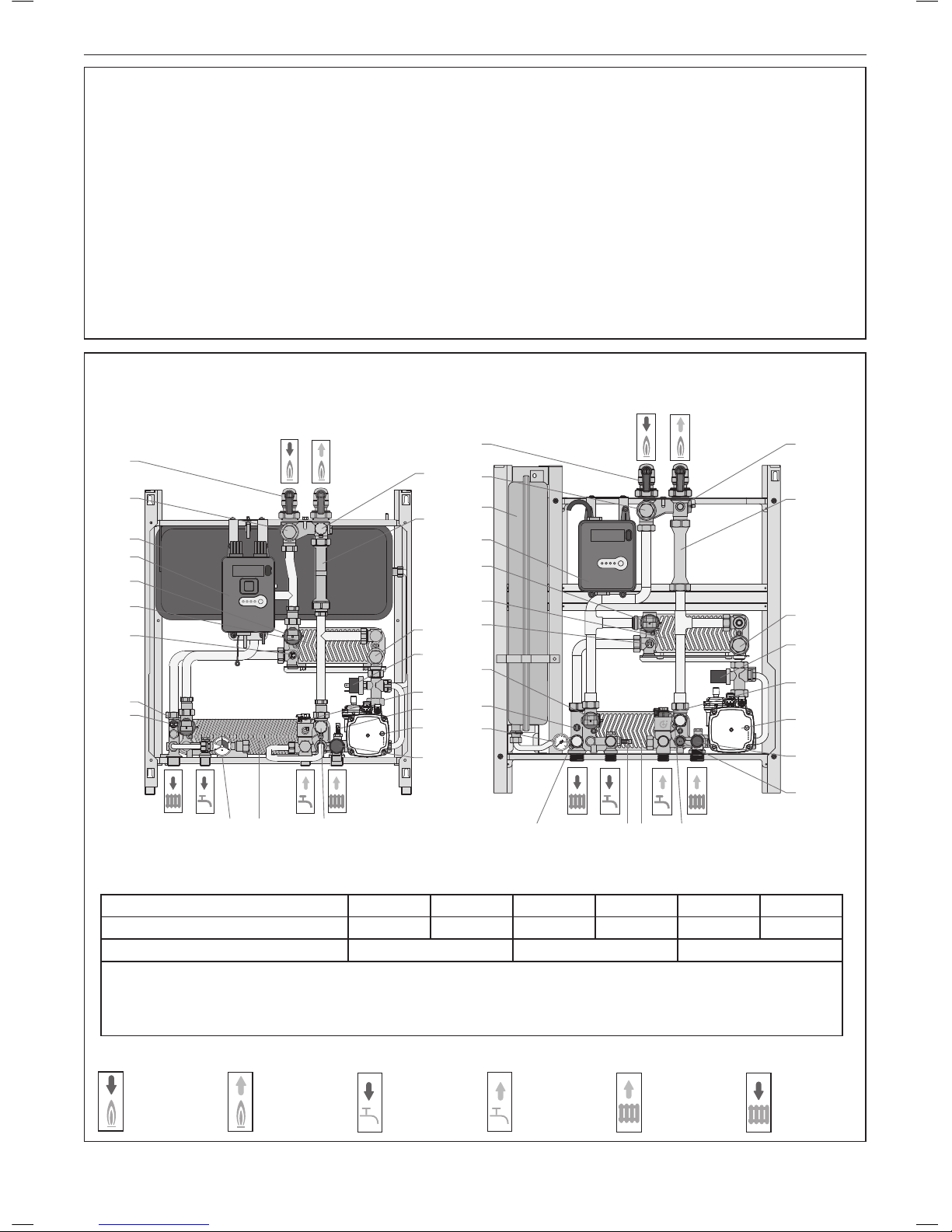
1 APPLIANCE TYPE
INDIRECT
LOGIC HIU INDIRECT 75
Indirect wall mounted HIU, with a 75kW instantaneous priority
DHW and 15 kW modulated CH. This can be converted to
under oor heating including inbuilt safety thermostat
capability.
LOGIC HIU INDIRECT 50
Indirect wall mounted HIU, with a 50kW instantaneous priority
DHW and 15 kW modulated CH. This can be converted to
under oor heating including inbuilt safety thermostat
capability.
Note: 75 Indirect unit is shown tted with lling loop attached (See Frame 13)

INDIRECT SPECIFICATION
5
LOGIC HIU -
Installation & Servicing / Users
2 TECHNICAL SPECIFICATION
OPERATION
Heating
The temperature setting operates on the principle of set point
regulation and can be xed within application limits.
Heating Set Point: 25 to 75°C
Nom. heating exchanger net output: 15 kW
Secondary circuit: Maximum pressure rating 3 bar Maximum
operating pressure 2.5 bar
Pump: UPM3 Auto L
Pump bypass setting: 0.45 bar
Pressure switch: opening 0.4 bar - closing 0.8 bar
Safety relief valve setting: 3 bar
Safety thermostat: 55˚C ±3
Expansion vessel: 7.5 litre
Optional Under oor heating capability
Heating control circuit is VOLT FREE
Domestic Hot Water - DHW
The DHW function takes priority over the heating
function controlled by the DHW priority ow switch
(component 10).
Set Point - DHW temperature 42 to 60°C
Domestic hot water: 10 bar
DHW circuit max. ow rate: 18 l/m (0.3 l/s)
Min.ow rate to activate domestic ow sensor: 2.7
l/m ±0.3
Max. Differential pressure on domestic water
modulating valve: Δp 1.65 bar
Min. Differential pressure on domestic water
modulating valve: Δp 0.35 bar
Heat exchanger capacity:
Nom. DHW heat exchanger net output: 50 kW Logic HIU Indirect 50
Nom. DHW heat exchanger net output: 75 kW Logic HIU Indirect 75
Optional Pre heat function
Primary Performance
Maximum working pressure: 16 bar - primary
3 bar - secondary
Maximum temperature: 85°C
Medium: Water
Max. Percentage of glycol 30%
Max. Recommended primary circuit ow rate: 1.2 m³/h
Electrical
Power supply: 230 V (ac)±10% 50 Hz
Power consumption: 80 W
Protection class: IP 40
Actuator: stepper 24 V
Probes: NTC 10 kΩ
Construction
Frame: RAL 9010 sprayed steel
Protective shell cover: PPE
Components: brass BS EN 12165 CW617N
Pipes: stainless steel
Exchanger: brazed stainless steel
LOGIC HIU INDIRECT 75, LOGIC HIU INDIRECT 50
INDIRECT SPECIFICATION
6
LOGIC HIU - Installation & Servicing / Users
ON DHW CHFAULT
RESET
21
18
10
RESET
ON DHW CH FAULT
1
2
2
1
0
3
4
bar
20
17
16
3
2
1
19
11
5
13
7
15
4
14
822
C D
2
E F
1
19
11
5
13
7
15
4
14
22
A B
2
C D E F
9 8 2
21
20
18
10
17
16
3
2
A B
DIMENSIONS
Primary
circuit ow
Key to Symbols Schematic -
Connection A B C D E F
Threads G1” G1” G ¾’ G ½” G ½’ G ¾’
Pitch A to B 65mm C to D 65mm E to F 65mm
Height 630mm
Width 550mm
Depth (inc cover) 265mm
Weight 19 Kg
3 ITEM COMPONENT REFERENCE: LOGIC HIU INDIRECT 75, LOGIC HIU INDIRECT 50
1 Primary isolation valve (incorporating pressure test points)
2 Drain cock
3 Heat meter spacer piece - replaced by heat meter when tted
4 Primary lter and heat meter probe pocket
5 Heating circuit control valve
7 Modulating primary control valve (DHW)
8 Plate heat exchanger (DHW)
9 DHW temperature sensor
10 DHW ow switch
11 Electronic control unit
12 Room controller (not supplied)*
13 Plate heat exchanger (space heating)
14 Heating ow temperature sensor
15 Temperature control stat
16 Strainer (heating circuit)
17 Pump safety bypass and DP switch
18 Pump
19 Expansion vessel
20 Safety relief valve - 3 bar
21 Heating return temperature sensor
22 Pressure gauge
23 Filling loop isolation valve*
24 Filling loop double check valve*
25 Filling loop*
* Not shown on Components illustration.
4 TECHNICAL SPECIFICATION
LOGIC HIU INDIRECT 75 LOGIC HIU INDIRECT 50
Primary
circuit return
Domestic
hot water
outlet
Domestic
cold water
inlet
Heating
circuit return
Heating
circuit ow

INDIRECT SPECIFICATION
Flowrate - l/s
Flowrate - l/s
COMMON
HEATING
SYSTEM
COMMON
HEATING
SYSTEM
7
LOGIC HIU -
Installation & Servicing / Users
FLOW PATH
Heating Primary Circuit
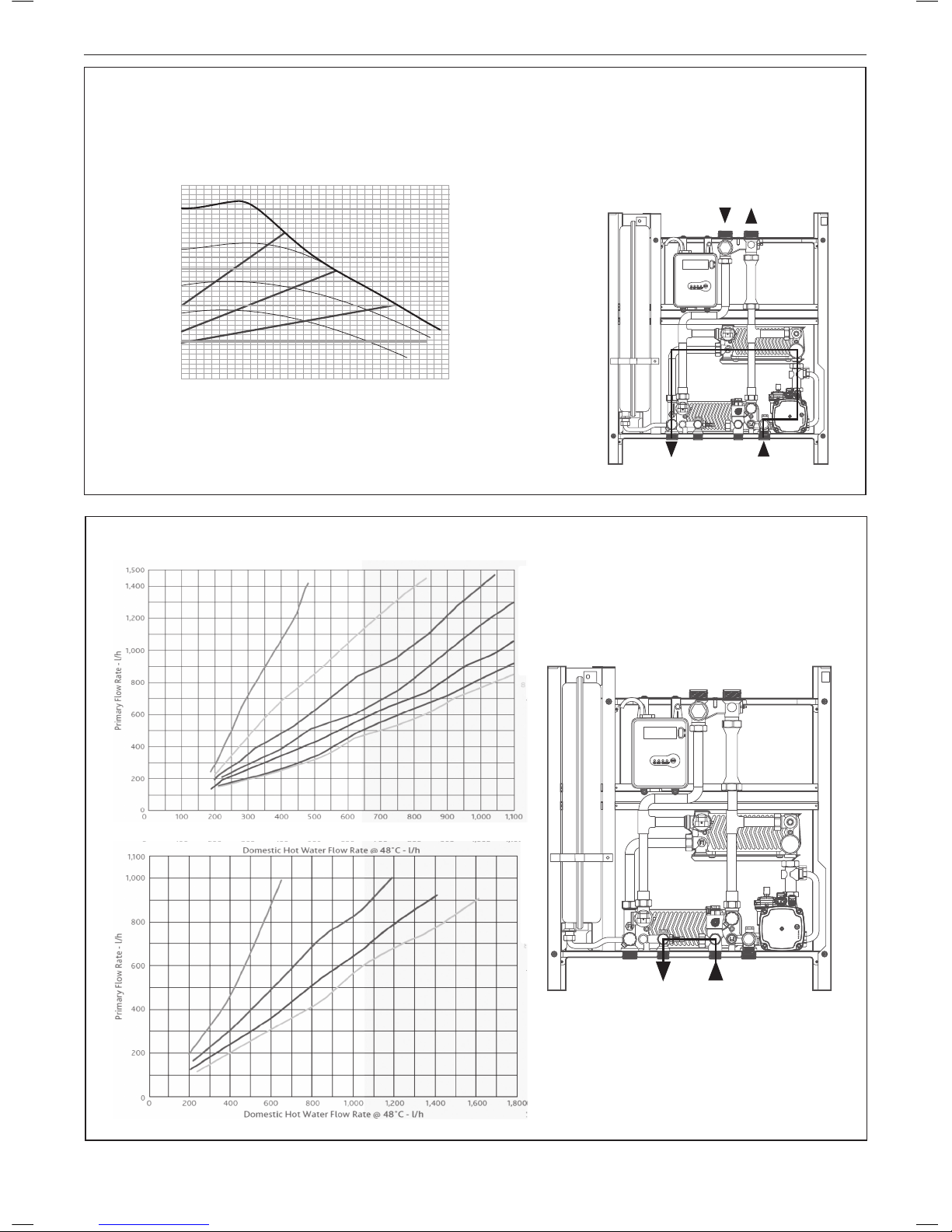
5 SCHEMATIC LOGIC HIU INDIRECT 75 & LOGIC HIU INDIRECT 50
6 PRIMARY FLOW CHARACTERISTICS
7 PRIMARY FLOW CHARACTERISTICS
FLOW PATH
DHW - Primary Circuit
RESET
ON DHW CHFAULT
1
2
RESET
ON DHW CHFAULT
1
2
Kv = 2.25 m3/h
Kv = 2.03 m3/h
Pressure loss - kPa Pressure loss - kPa
INDIRECT SPECIFICATION
8
LOGIC HIU - Installation & Servicing / Users
8 HEATING FLOW CHARACTERISTICS FOR LOGIC HIU INDIRECT 75 & 50
9 DHW FLOW CHARACTERISTICS FOR LOGIC HIU INDIRECT 75 & 50
RESET
ON DHW CHFAU LT
1
2
RESET
ON DHW CH FAULT
1
2
55ºC
65ºC
55ºC
85ºC
75ºC
85ºC
80ºC
75ºC
70ºC
65ºC
60ºC
HEATING SECONDRY
FLOW CHARACTERISTICS
LOGIC HIU INDIRECT 50 & 75
DHW SECONDRY FLOW
CHARACTERISTICS
LOGIC HIU INDIRECT 50 & 75
HEATING
FLOW
HEATING
RETURN
DHW
OUT
MAINS
DHW
FEED
COMMON HEATING
SYSTEM
Δ
H (m c.a.)
H (m c.a.)
p (bar)
3 3,5
G (m3/h)
0,6
0,4
0,3
0,2
0,1
0
2,521,5
0,5
0,5
1
6
4
3
2
1
5
70,7
0,8 8
Flowrate - l/s
Pressure loss - kPa

INDIRECT HARDWARE CONTENTS
9
LOGIC HIU -
Installation & Servicing / Users
11 PRIMARY BALL VALVE SET
Flow & Control Valves (with sample points). (Inc. sealing washer to appliance)
CONTENT
Item Qty Component
1 2 16 Bar primary inlet ball valves with integrated pressure sampling points ¾”
BSP Union connection x ¾” BSP ball valve with union end and male threaded
connection joint*.
2 2 Rubber washers for union end connection and
2 Fibre washes for ¾” BSP connection face
12 DOMESTIC CONNECTION FLOW & RETURN VALVE KIT
(Inc. sealing washer to appliance)
CONTENT
Item Qty Component CH inlet and outlet connection valves (Inc. sealing washer to appliance)
2 2 22mm x ¾” ball valve with union end and compression joint* - one blue and one red handle.
3 Small component pack consisting of: 2 ¾” seal for union joint
DHW inlet and outlet connection valves (Inc. sealing washer to appliance)
1 2 15mm x ½” ball valve with union end and compression joint*.
2 15mm compression nut
2 15mm olive
13 FILLING LOOP CONNECTION KIT VALVES
(Inc. sealing washer to appliance & water check valve incorporated into inlet connection)
The lling loop and ball valves are used to ll and pressurise the secondary heating system,
the lling loop must be disconnected after pressurisation to comply with the Water Regulations.
CONTENT
Item Qty Component CH inlet and outlet connection valves
1 1 Ball valve with integral check valve and union joint.
2 1 Ball valve with union joint
3 1 Flexible hose 250mm long
4 2 ½” rubber sealing washer for union joint - black
5 2 Sealing washer for exible hose – green.
14 OPTIONAL FLUSHING BY-PASS
(Inc. Union built in rubber sealing washer)
Check the components in the kit before commencing. It is strongly
recommended the ushing by-pass option kit is tted as it allows for
cleaning of the primary water system loop whilst the HIU is tted.
1 ‘H’ pattern ushing bypass valve
2 Threaded male union tail piece - 4 off.
Install tails into HIU inlet connections
Fit Flushing by pass
Connect to primary pipe work
Turn screw driver slot horizontal to bypass.
Turn Vertical to connect the HIU to the primary circuit
10 LOGIC HIU INDIRECT 50 OR LOGIC HIU INDIRECT 75
* Compression ends complying with BS EN 1254-2 for use with R250 (half hard) copper tube
2
1
10
LOGIC HIU - Installation & Servicing / Users
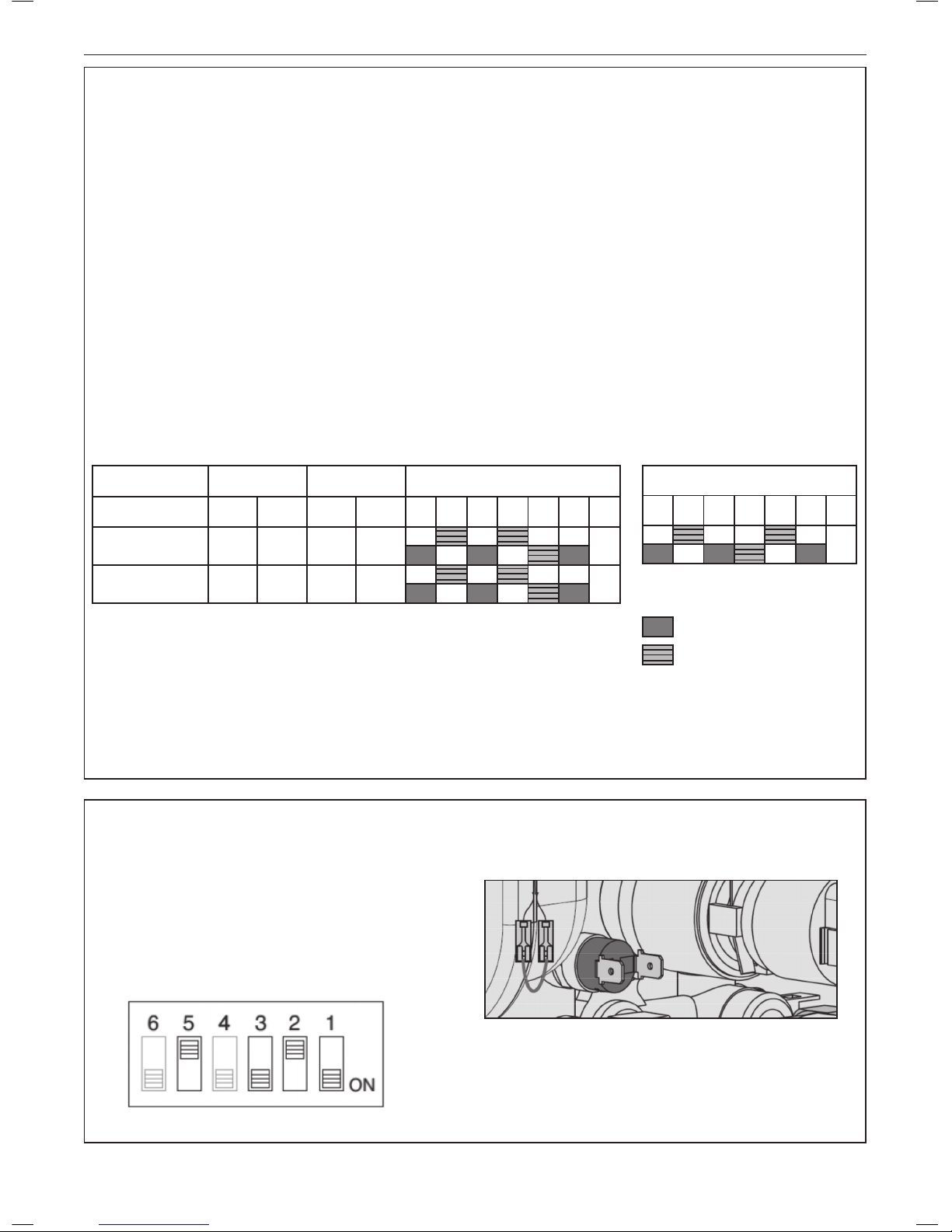
15 ELECTRONIC CONTROLLER
LOGIC HIU INDIRECT 50 & 75 KW UNITS
All the heating and domestic hot water functions offered by the
Logic Indirect HIUs are controlled by a digital controller.
The controller is factory set with the parameters for the HIU
unit ordered.
The Logic Indirect HIU versions offer the optional capability
to be converted for use on under oor heating by controlling
the CH central heating temperature below 45 C and the
activation of the safety thermostat that prevent the CH circuit
going above 45 °C. This can be achieved by setting the DIP
switches found inside the control box to the positions shown in
the sub table below (right-hand side).
Automatic controller functions
Reset mixing/modulating valve to zero - Immediately after the
power supply has been switched on, the position of the mixing/
modulating valves is reset to zero.
Pump anti-sieze - When the pump is not in use, it is powered
on for a period of 5 seconds every 24 hours.
Mixing valve/modulating valve anti-sieze - The anti-sieze cycle
for the mixing/modulating valve is run every 24 hours.
IMPORTANT
These DIP switches congure the control for different units
within the range. It is important that they are not changed
from those shown below. If they carehanged outside of these
requirements, it will cause the HIU to operate incorrectly and
may result in hazardous operational conditions.
Electronic Control
Dip Switch Settings
Factory Settings Setting Capability Production settings
Type Heating DHW Heating DHW 6 5 4 3 2 1
Logic HIU Indirect 50 75 54 25 to 75 42 to 60
ON
Logic HIU Indirect 75 75 54 25 to 75 42 to 60
ON
Underoor Low Temp Settings
6 5 4 3 2 1
ON
Do not change
Can be Changed
OPTION Indirect only
Switch 1 Modulating temperature regulation with compensated set point
Switch 2 & 3 Conversion to & from Low temperature to high temperature CH
Switch 5 Domestic water pre heating function
TABLE 1
To modify the factory settings, and enable the HIU to support low temperature systems 25 to 45ºC proceed as follows
16 CONVERTING THE UNIT TO UNDERFLOOR OPERATION
(LOGIC HIU INDIRECT 50 & 75KW UNITS)
To convert the unit to an underoor low temperature system
(25 to 45°C operation range)
1 Switch off the electricity power supply to the HIU
2 Set the switches 2 and 3 with the ON-OFF setting
3 Remove the safety thermostat jumper cable and connect
the cables to the thermostat.
4 Switch on the electricity power supply to the HIU.
INDIRECT ELECTRONIC CONTROL
 Loading...