

IDEAL Logic HIU 50 Indirect, Logic HIU 75 Indirect, Logic HIU 50 Direct MT, Logic HIU 50 Direct HT Product Manual
Page 1
PRODUCT GUIDE
WE HAVE IT COVERED.
LOGIC HEAT
INTERFACE UNITS
(HIUs)
Page 2
02
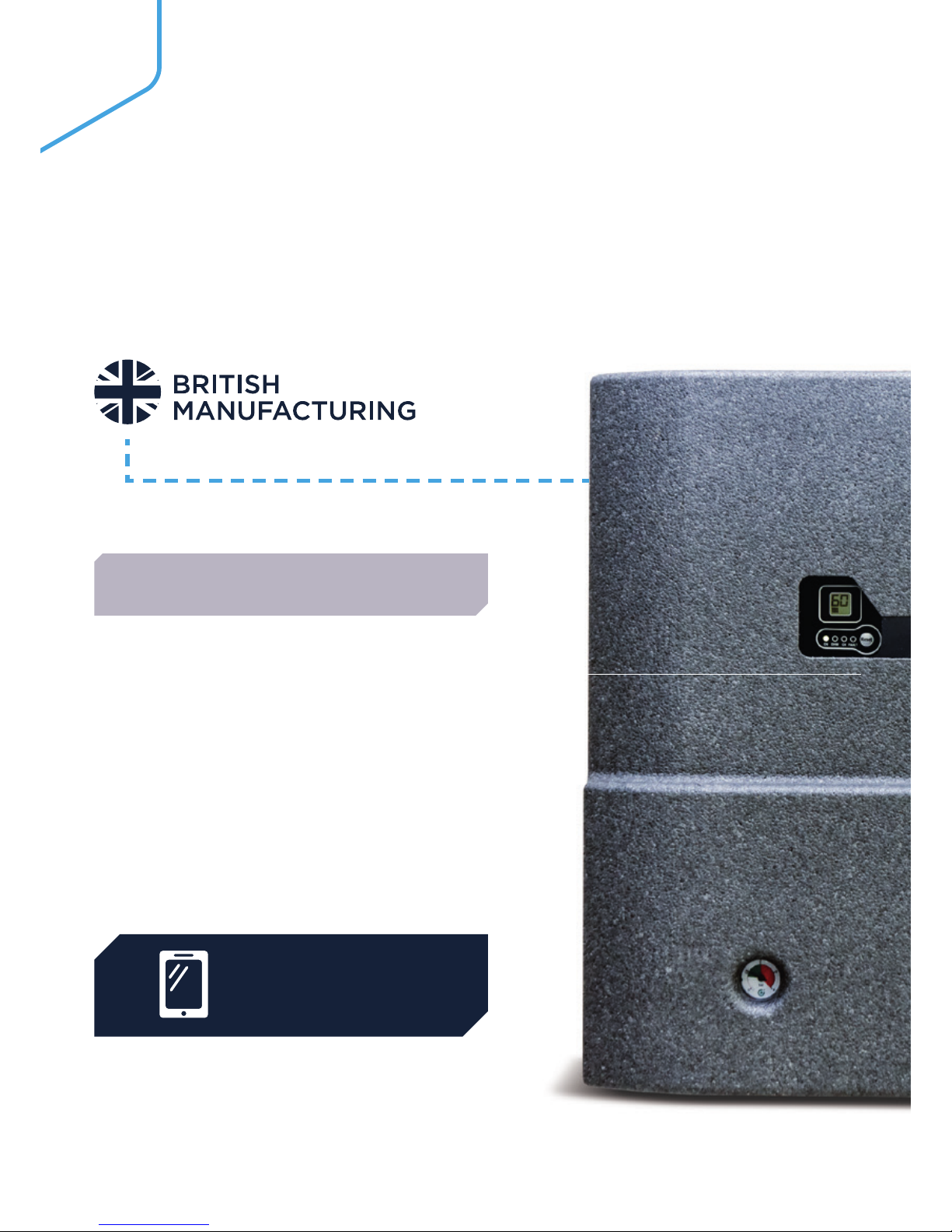
Ideal Commercial Boilers is the UK’s market leader of
high efficiency commercial heating solutions.
Operating from its Hull manufacturing plant and offices
since 1906, Ideal Commercial Boilers is one of the few
true British manufacturers left in the heating industry.
Your phone or tablet can let you
appreciate our Condensing Boiler range
in a new dimension.
The Ideal Commercial Eye app uses
the latest technology to project 3D
renders from the page of this brochure
on to your device.
To see this for yourself, simply download the
Ideal Commercial Eye app for free from your
device’s app store. Open the app and then
place your device over the image that has
this icon next to it:
DOWNLOAD
THE APP
BRING BOILERS TO LIFE
Page 3
03
4 HIU Introduction
Logic HIU range
6-9 Logic HIU 50 Indirect
10-13 Logic HIU 75 Indirect
14-17 Logic HIU 50 Direct MT
18-20 Logic HIU 50 Direct HT
Metering & Accessories
21 CF Echo II
21 CF UltramaxX V
21 Accessories
Condensing Boiler range
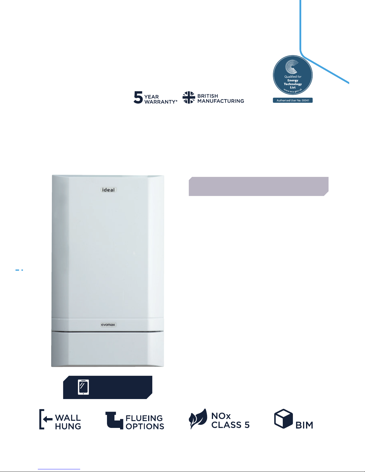
23 Evomax
24-25 Evomax Cascade
26 Imax Xtra
27 Imax Xtra EL
28 Evomod
29 Evojet
30-31 Commercial range overview
32-33 Stelrad radiators
34-35 Ideal Training & Support
Page 4
04
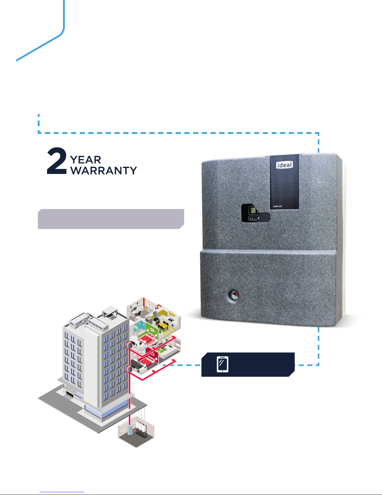
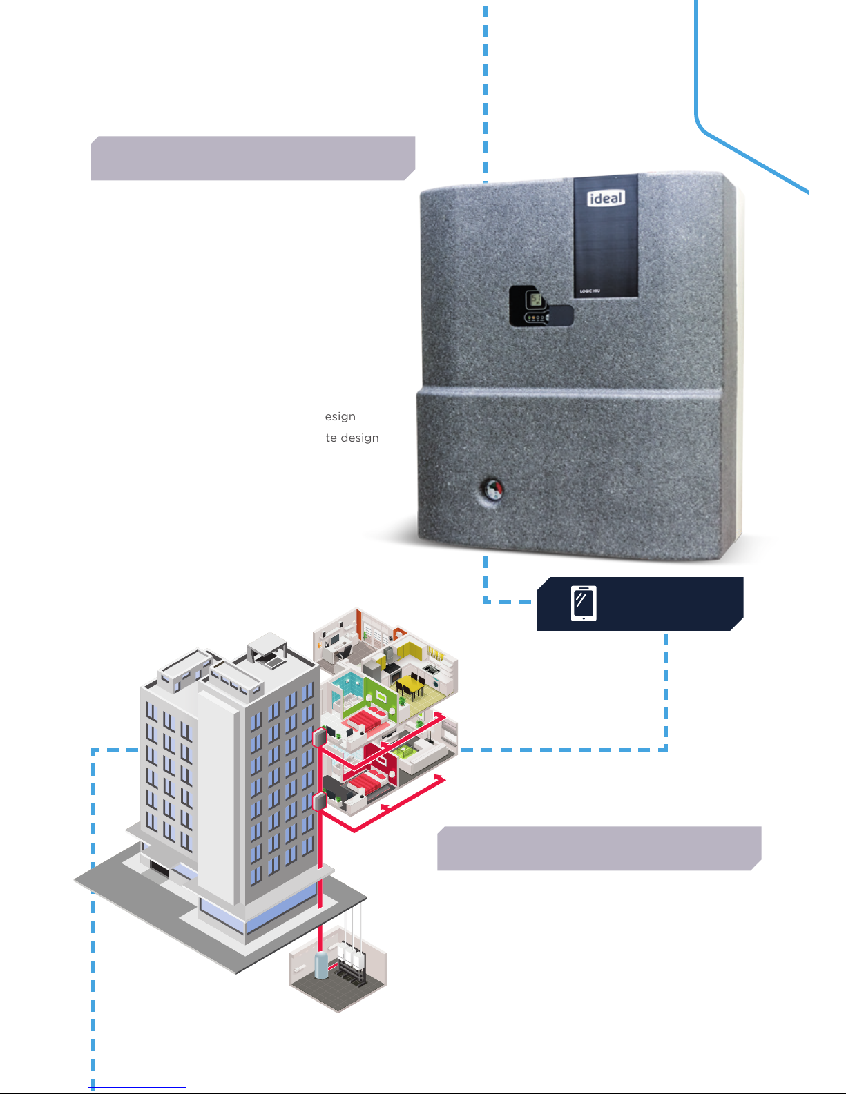
TYPICAL
SYSTEM.
DOWNLOAD
THE APP
LOGIC HIU
INTRODUCTION
The Ideal Heat Interface Units are heat energy transfer
units. Designed for use in conjunction with centralised
boilers, district heating or central energy systems. The
function is to efficiently transfer heat from the plant
room to the individual dwelling’s central heating (CH)
and domestic hot water (DHW) systems.
TYPICAL SYSTEM
Page 5

05
Ideal HIUs incorporate an internal electronic control
unit which ensures not only maximum efficiency,
improved reaction time and control but also
incorporates other additional features.
Modulating valves control the supply of hot water to
both the space heating and domestic hot water within
the apartment.
The thermally insulated casings minimise heat loss
from the unit.
Maximum energy saving from the HIUs can only be
achieved if the system is designed correctly and HIUs
are selected and sized correctly.
To ensure maximum efficiency, reliability and
performance the system must be designed and
commissioned in accordance with CIBSE.
IDEAL LOGIC HIU
BENEFITS
THE BENEFITS OF IDEAL LOGIC HIUs ARE:
• Compact design requiring a minimum amount of space
• Minimal routine maintenance since they do not require
regular servicing or maintenance
• All the Logic HIUs incorporate a spacer piece which can
be easily removed and a heat meter fitted inside the unit.
This allows the energy used by each individual apartment
to be recorded and charged accordingly
THE LOGIC HIU RANGE HAS TWO METER
OPTI O N S AVAI L AB L E :
• CF ECHO II
• CF ULTRAMAXX V
Depending upon the meter chosen the energy used can
be monitored and recorded automatically which enables
automatic billing to the tenants.
For information on how to design Ideal Logic HIUs
into you next project please refer to the Design Guide which
covers:
• Unit selection
• Heating system layout
• Integration of low carbon heat sources
• Prediction of hot water simultaneous demands
SAP has been adopted by the Government as part of
the UK’s national standard for calculating the energy
performance of buildings.
Every new building has to have an SAP rating. It provides a
simple means of reliably estimating the energy efficiency.
SAP ratings are expressed on a scale of 1 to 100, the higher
the number the more energy efficient the building.
SAP RATING
Page 6
06
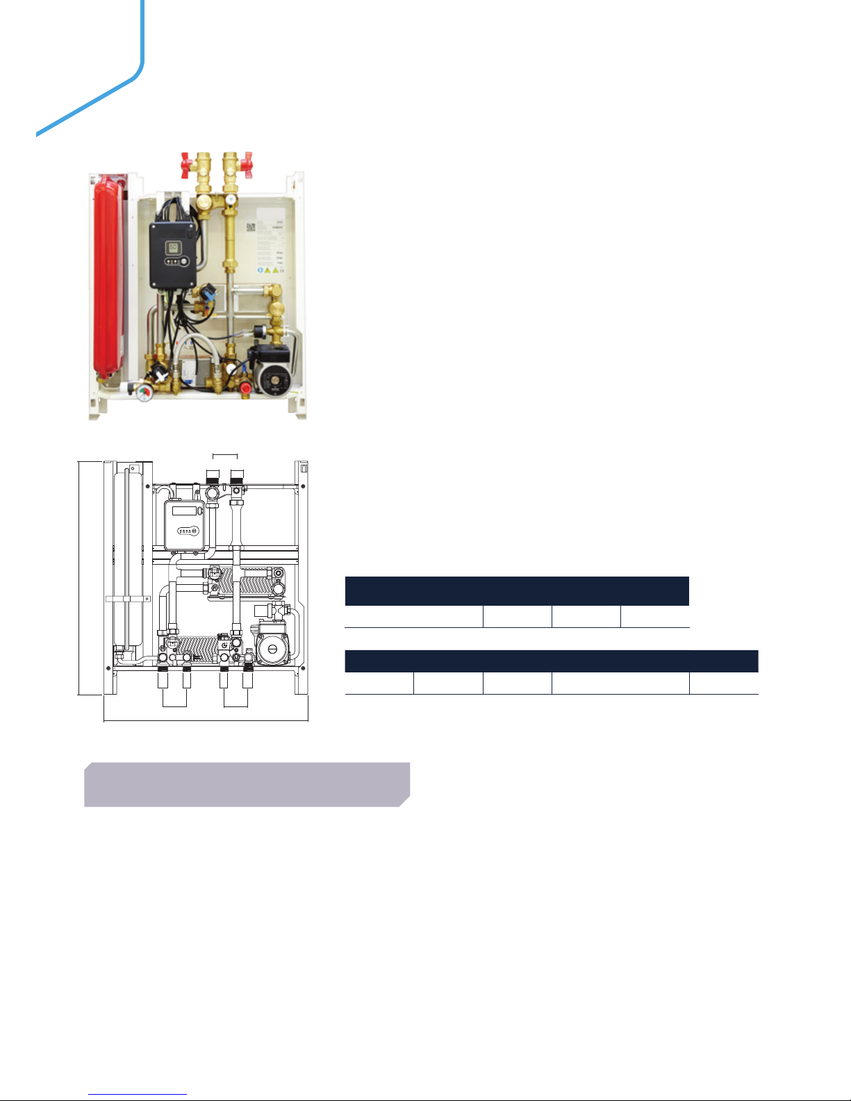
* After shut-off valves are installed the connections become a female 3/4’’.
CONNECTION A B C
Thread G¾” G½” G1”*
D E F Depth inc. Cover kg
65mm 550mm 630mm 265mm 19
F
A ABB
D
D
E
D
C
C
• Twin plate design hydraulically separates both domestic
and space heating from the central primary supply
• Internal electronic control unit with LCD display
• The standard unit can be set to hold a stable heating
flow temperature, to suit the installation (radiators, UFH
for example), but crucially, can also be set to vary the
heating flow temperature automatically depending on the
temperature of the heating return water
• Automatically compensates for changes due to external
influences, such as outside temperature etc. thereby
ensuring that the unit and the system operate at maximum
efficiency
• Pump bypass protection, in case of complete radiator
TRV shutdown
• Compact and lightweight
• Fully insulated EPP front cover
• Convertible to underfloor heating
• Configurable hot water priority
• Pressure independent control valve
• Ability to pre-heating of the DHW exchanger
FEATURES & BENEFITS
The Logic heat interface unit is the latest
‘intelligent’ range of HIU from Ideal. The Logic
HIU is the complete solution for instantaneous
hot water production and space heating control.
This is an indirect wall mounted HIU, providing
50 kW instantaneous priority DHW and 15 kW
modulated CH. This can be converted to under
floor heating including inbuilt safety thermostat
capability.
LOGIC HIU
50 INDIRECT
Page 7

07
Maximum working pressure: 16 bar - primar y
3 bar - secondary
Maximum temperature 85°C
Max. Percentage of glycol 30%
Max. Recommended primary
circuit flow rate
1.2 m³/h
PRIMARY PERFORMANCE
Heat Interface Unit 50
Primary ball valve set
Domestic connection flow & return valve kit
Filling loop connection kit valves
Flushing By-pass
CF Echo II
CF Ultramaxx V
UIN PRODUC T NAME METERING OPTIONS
211094 Logic HIU Indirect 50
HIU only, meter not
included
211347 Logic HIU Indirect 50
Factory fitted, CF Echo 11
MbBus 1
211351 Logic HIU Indirect 50
Factory fitted, CF
Ultramaxx V MBus PS
Power supply 230 V (ac)±10% 50 Hz
Max. Power consumption 105 W
Protection class IP 40
Actuator Stepper 24 V
Probes NTC 10 kΩ
ELECTRICAL
Frame RAL 9010 sprayed steel
Protective shell cover EPP (Expanded polypropylene)
Components Brass BS EN 12165 CW617N
Pipes Stainless steel
Exchanger Brazed stainless steel
CONSTRUCTION
INCLUDED AS STANDARD
ACCESSORIES
The temperature setting operates on the principle of set
point regulation and can be fixed within application limits.
Heating Set Point 25 to 75°C
Nom. heating exchanger net
output:
15 kW
Secondary circuit: Maximum pressure rating 3 bar
Maximum operating pressure
2.5 bar
Pump UPS 15/60
Pump bypass setting 0.45 bar
Pressure switch Opening 0.4 bar
Closing 0.8 bar
Safety relief valve setting 3 bar
Safety thermostat 55˚C ±3
Expansion vessel 7.5 litre
Under floor heating capability Optional
Heating control circuit VOLT FREE
HEATING
The DHW function takes priority over the heating function
controlled by the DHW priority flow switch.
Set Point DHW temperature 42 to 60°C
Max. Domestic hot water
pressure
10 bar
DHW circuit max. flow rate 18 l/m (0.3 l/s)
Min. flow rate to activate
domestic flow sensor
2.7 l/m ±0.3
Max. Differential pressure on
domestic water modulating
valve
Δp 1.65 bar
Min. Differential pressure on
domestic water modulating
valve
Δp 0.35 bar
Nom. DHW heat exchanger
net output
50 kW - Logic HIU
50 Indirect
DOMESTIC HOT WATER - DHW
INCLUDING OPTIONAL PRE HEAT FUNCTION
Page 8
08
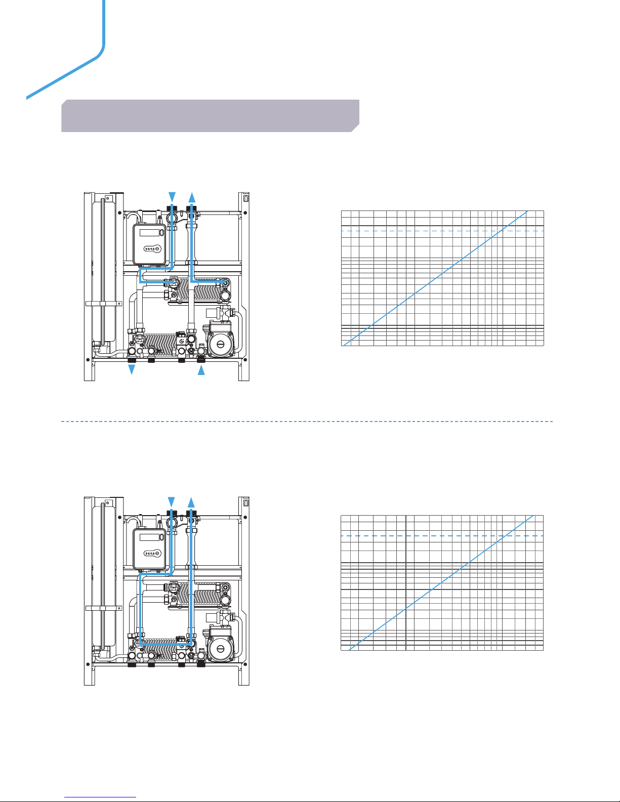
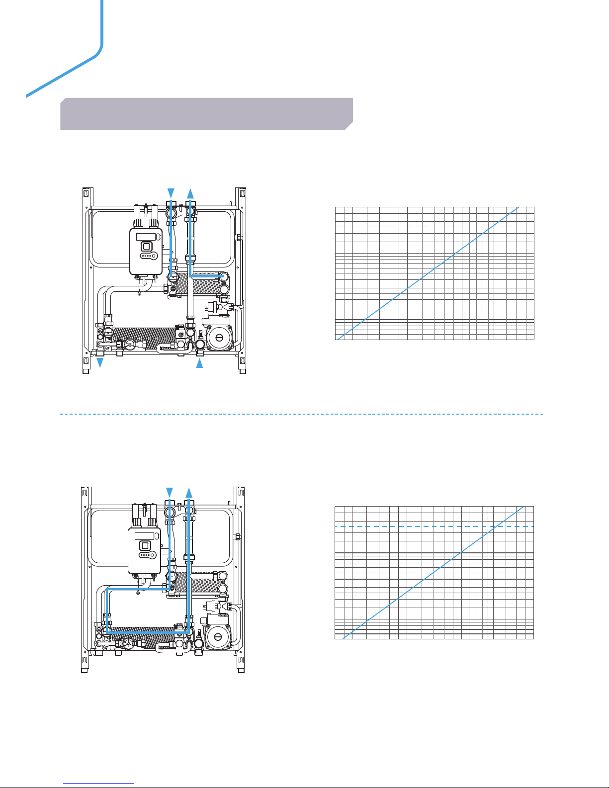
HYDRAULIC CHARACTERISTICS DOMESTIC HOT WATER - PRIMARY SIDE
HYDRAULIC CHARACTERISTICS HEATING - PRIMARY SIDE
DOMESTIC HOT WATER
0.04 0.06 0.08 0.1 0.2 0.3 0.4 0.5
Flowrate - l/s
50
10
1
0.5
20
30
2
3
5
Pressure loss - kPa
Kv = 2.03 m³/h
Flow Path
Heating - primary side
ONON DHWDHW CHCH FAFAULULTT
RRESETESET
11
22
HR
HF
CHS
HEATI N G
CHS
HRHF
DHW - heat exchanger
0.04 0.06 0.08 0.1 0.2 0.3 0.4 0.5
0.04 0.06 0.08 0.1 0.2 0.3 0.4 0.5
Flowrate - l/s
50
10
1
0.5
20
30
2
3
5
Pressure loss - kPa
Kv = 2.25 m³/h
Hydraulic Characteristics
Heating - secondary side
Flow Path
Heating - secondary side
ONON DHWDHWCHCHFAFAULULTT
RRESETESET
11
22
CHS
0
10
20
30
40
50
60
0 0.1 0.2 0.3 0.4 0.5 0.6
Flowrate -l/s
Pressure loss -kPa
3
2
1
Kv = 2.63 m³/h
UPS 15 - 60 pump settings
ONON DHWDHW CHCH FAFAULULTT
RRESETESET
11
22
CHS
HRHF
DHW - heat exchanger
Flowrate - l/s
50
10
1
0.5
20
30
2
3
5
Pressure loss - kPa
Kv = 2.03 m³/h
Flow Path
Heating - primary side
ONON DHWDHW CHCH FAFAULULTT
RRESETESET
11
22
HR
HF
CHS
CHS
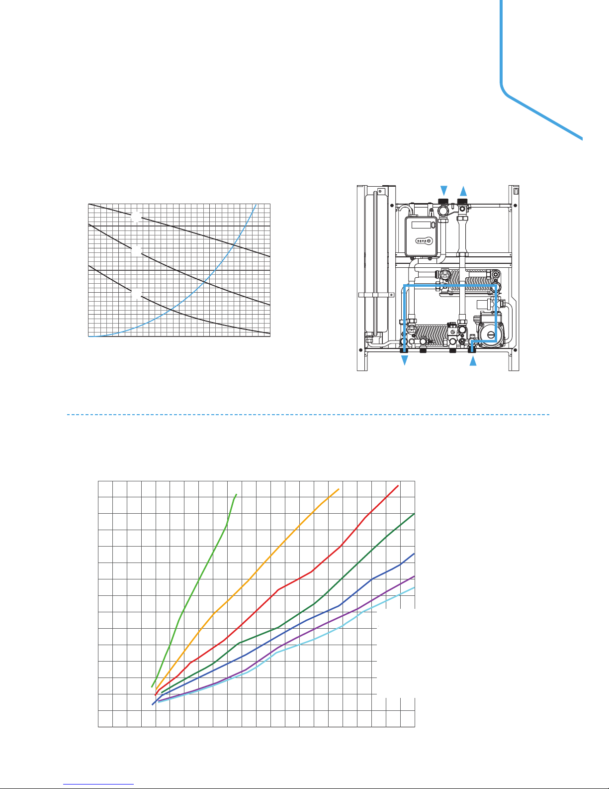
PRIMARY FLOW CHARACTERISTICS
Page 9
09
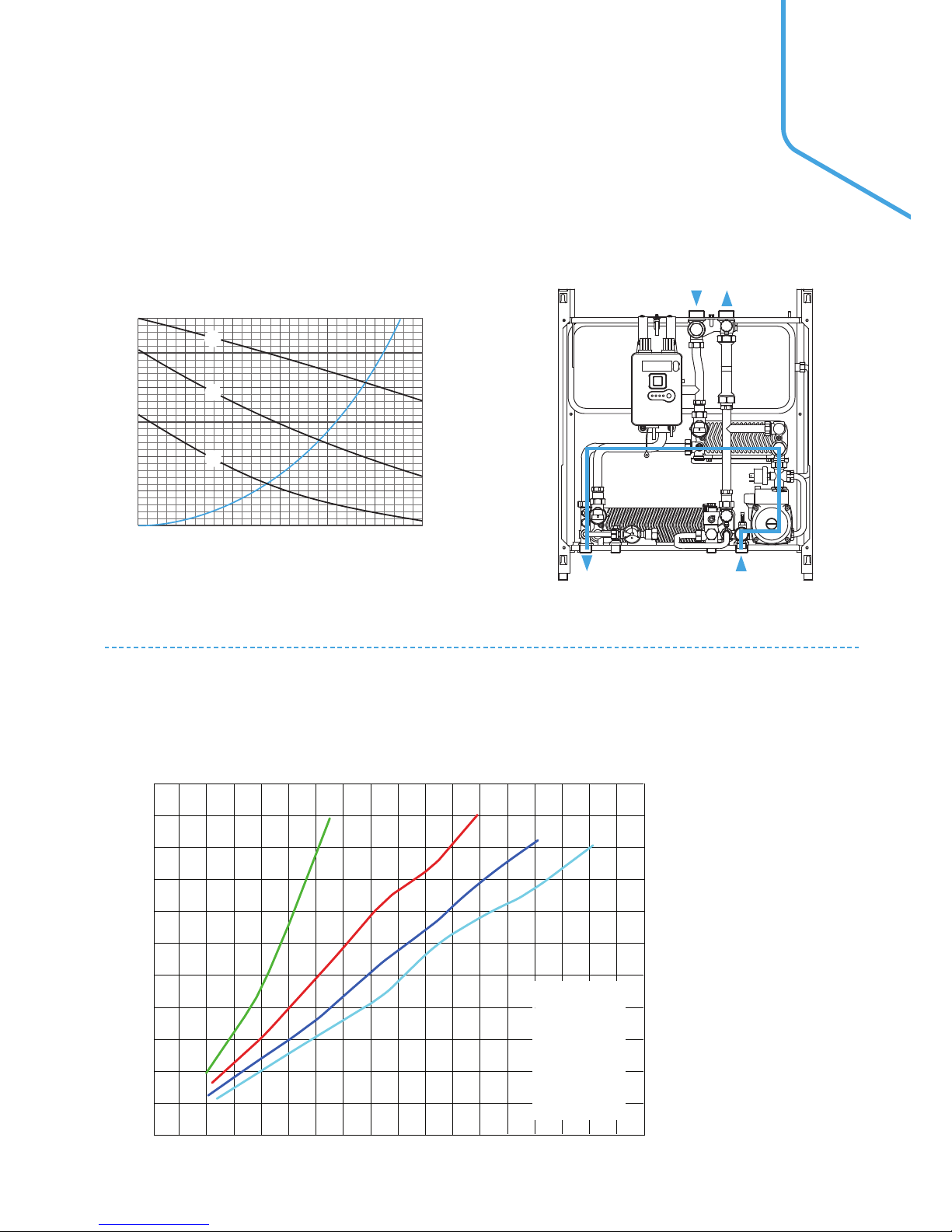
HYDRAULIC CHARACTERISTICS HEATING - SECONDARY SIDE
0.04 0.06 0.08 0.1 0.2 0.3 0.4 0.5
Hydraulic Characteristics
Heating - secondary side
Flow Path
Heating - secondary side
0
10
20
30
40
50
60
0 0.1 0.2 0.3 0.4 0.5 0.6
Flowrate -l/s
Pressure loss -kPa
3
2
1
Kv = 2.63 m³/h
UPS 15 - 60 pump settings
ONON DHWDHW CHCH FAFAULULTT
RRESETESET
11
22
CHS
HRHF
Flowrate - l/s
50
10
1
0.5
20
30
2
3
5
Pressure loss - kPa
Kv = 2.03 m³/h
Flow Path
Heating - primary side
ONON DHWDHW CHCH FAFAULULTT
RRESETESET
11
22
HR
HF
CHS
CHS
HRHF
Primary Flow Rate I/h
Primary flow temperatures
1,500
1,400
1,200
1,000
800
600
400
200
0
0 100 200 300 400 500 600 700 800 900 1,000 1,100
Domestic Hot Water Flow Rate @ 48˚C - l/h
55˚C
60˚C
65˚C
70˚C
75˚C
80˚C
85˚C
Primary flow temperatures
55˚C
60˚C
65˚C
70˚C
75˚C
80˚C
85˚C
Primary flow temperatures
55˚C
60˚C
65˚C
70˚C
Primary
flow temperatures
temperatures
DOMESTIC HOT WATER OUTPUT
Page 10
10
ON DHW CH FAULT
RESET
F
A ABB
D
D
E
D
C
C
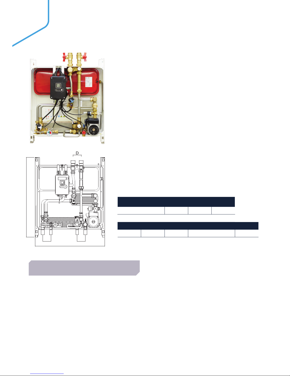
* After shut-off valves are installed the connections become a female 3/4’’.
CONNECTION A B C
Thread G¾” G½” G1”*
D E F Depth inc. Cover kg
65mm 550mm 630mm 265mm 19
• Twin plate design hydraulically separates both domestic
and space heating from the central primary supply
• Internal electronic control unit with LCD display
• The standard unit can be set to hold a stable heating
flow temperature, to suit the installation (radiators, UFH
for example), but crucially, can also be set to vary the
heating flow temperature automatically depending on the
temperature of the heating return water
• Automatically compensate for changes due to external
influences, such as outside temperature etc. thereby
ensuring that the unit and the system operate at maximum
efficiency
• Convertible to underfloor heating
• Configurable hot water priority
• Pressure independent control valve
• Pump bypass protection, in case of complete radiator TRV
shutdown
• Ability to pre-heating of the DHW exchanger
FEATURES & BENEFITS
The Logic heat interface unit is the latest
‘intelligent’ range of Logic HIUs from Ideal.
The Logic HIU is the complete solution for
instantaneous hot water production and space
heating control.
This is an indirect wall mounted HIU, providing
75 kW instantaneous priority DHW and 15 kW
modulated CH. This can be converted to under
floor heating including inbuilt safety thermostat
capability.
LOGIC HIU
75 INDIRECT
Page 11

11
Maximum working pressure: 16 bar - primar y
3 bar - secondary
Maximum temperature 85°C
Max. Percentage of glycol 30%
Max. Recommended primary
circuit flow rate
1.2 m³/h
PRIMARY PERFORMANCE
Heat Interface Unit 75
Primary ball valve set
Domestic connection flow & return valve kit
Filling loop connection kit valves
Flushing By-pass
CF Echo II
CF Ultramaxx V
UIN PRODUC T NAME METERING OPTIONS
211093 Logic HIU Indirect 75
HIU only, meter not
included
211346 Logic HIU Indirect 75
Factory fitted, CF Echo 11
MbBus 1
211350 Logic HIU Indirect 75
Factory fitted, CF
Ultramaxx V MBus PS
Power supply 230 V (ac)±10% 50 Hz
Max. Power consumption 105 W
Protection class IP 40
Actuator Stepper 24 V
Probes NTC 10 kΩ
ELECTRICAL
Frame RAL 9010 sprayed steel
Protective shell cover EPP (Expanded polypropylene)
Components Brass BS EN 12165 CW617N
Pipes Stainless steel
Exchanger Brazed stainless steel
CONSTRUCTION
INCLUDED AS STANDARD
ACCESSORIES
The temperature setting operates on the principle of set
point regulation and can be fixed within application limits.
Heating Set Point 25 to 75°C
Nom. heating exchanger net
output:
15 kW
Secondary circuit: Maximum pressure rating 3 bar
Maximum operating pressure
2.5 bar
Pump UPS 15/60
Pump bypass setting 0.45 bar
Pressure switch Opening 0.4 bar
Closing 0.8 bar
Safety relief valve setting 3 bar
Safety thermostat 55˚C ±3
Expansion vessel 7.5 litre
Under floor heating capability Optional
Heating control circuit VOLT FREE
HEATING
The DHW function takes priority over the heating function
controlled by the DHW priority flow switch.
Set Point DHW temperature 42 to 60°C
Max. Domestic hot water
pressure
10 bar
DHW circuit max. flow rate 26.6l/m (0.44l/s)
Min. flow rate to activate
domestic flow sensor
2.7 l/m ±0.3
Max. Differential pressure on
domestic water modulating
valve
Δp 1.65 bar
Min. Differential pressure on
domestic water modulating
valve
Δp 0.35 bar
Nom. DHW heat exchanger
net output
75 kW - Logic HIU
75 Indirect
DOMESTIC HOT WATER - DHW
INCLUDING OPTIONAL PRE HEAT FUNCTION
Page 12
12
HYDRAULIC CHARACTERISTICS DOMESTIC HOT WATER - PRIMARY SIDE
HYDRAULIC CHARACTERISTICS HEATING - PRIMARY SIDE
DOMESTIC HOT WATER
0.04 0.06 0.08 0.1 0.2 0.3 0.4 0.5
Flowrate - l/s
50
10
1
0.5
20
30
2
3
5
Pressure loss - kPa
Kv = 2.03 m³/h
Flow Path
Heating - primary side
ONON DHWDHW CHCH FAFAULULTT
RRESETESET
11
22
HR
HF
CHS
HEATI N G
DHW - heat exchanger
0.04 0.06 0.08 0.1 0.2 0.3 0.4 0.5
0.04 0.06 0.08 0.1 0.2 0.3 0.4 0.5
Flowrate - l/s
50
10
1
0.5
20
30
2
3
5
Pressure loss - kPa
Kv = 2.25 m³/h
Hydraulic Characteristics
Heating - secondary side
Flow Path
Heating - secondary side
ONON DHWDHWCHCHFAFAULULTT
RRESETESET
11
22
CHS
0
10
20
30
40
50
60
0 0.1 0.2 0.3 0.4 0.5 0.6
Flowrate -l/s
Pressure loss -kPa
3
2
1
Kv = 2.63 m³/h
UPS 15 - 60 pump settings
ONON DHWDHW CHCH FAFAULULTT
RRESETESET
11
22
CHS
HRHF
DHW - heat exchanger
Flowrate - l/s
50
10
1
0.5
20
30
2
3
5
Pressure loss - kPa
Kv = 2.03 m³/h
Flow Path
Heating - primary side
ONON DHWDHW CHCH FAFAULULTT
RRESETESET
11
22
HR
HF
CHS
PRIMARY FLOW CHARACTERISTICS
ON DHW CH FAULT
RESET
CHS
ON DHW CH FAULT
RESET
CHS
HRHF
Page 13
13
1,100
1,000
800
600
400
200
0
0 200 400 600 800 1,000 1,200 1,400 1,600 1,800
Domestic Hot Water Flow Rate @ 48˚C - l/h
Primary Flow Rate I/h
Primary flow temperatures
55˚C
65˚C
75˚C
85˚C
Primary
flow temperatures
temperatures
Primary flow temperatures
55˚C
65˚C
Primary flow temperatures
55˚C
65˚C
75˚C
85˚C
HYDRAULIC CHARACTERISTICS HEATING - SECONDARY SIDE
0.04 0.06 0.08 0.1 0.2 0.3 0.4 0.5
Hydraulic Characteristics
Heating - secondary side
Flow Path
Heating - secondary side
0
10
20
30
40
50
60
0 0.1 0.2 0.3 0.4 0.5 0.6
Flowrate -l/s
Pressure loss -kPa
3
2
1
Kv = 2.63 m³/h
UPS 15 - 60 pump settings
ONON DHWDHW CHCH FAFAULULTT
RRESETESET
11
22
CHS
HRHF
Flowrate - l/s
50
10
1
0.5
20
30
2
3
5
Pressure loss - kPa
Kv = 2.03 m³/h
Flow Path
Heating - primary side
ONON DHWDHW CHCH FAFAULULTT
RRESETESET
11
22
HR
HF
CHS
DOMESTIC HOT WATER OUTPUT
ON DHW CH FAULT
RESET
CHS
HRHF
Page 14

14
* After shut-off valves are installed the connections become a female 3/4’’.
** Not shown on components illustration.
CONNECTION A B C
Thread G¾” G½” G1”*
D E F Depth inc. Cover kg
65mm 450mm 550mm 265mm 16
• Single plate design hydraulically separates the domestic
water with the space heating supplied directly from the
central primary supply
• Internal electronic control unit with LCD display
• Can be set to modulate the heating flow circuit for greater
efficiency and to compensate for changes in the external
environment
• Complete with a heating support pump, as standard,
including a pump bypass loop in case of complete radiator
TRV shutdown
• Compact and lightweight
• Fully insulated EPP front cover
• Includes differential pressure control valve (DPCV)**
supplied and fitted to the base of the unit
• Ability to pre-heating of the DHW exchanger
FEATURES & BENEFITS
The Logic heat interface unit is the latest
‘intelligent’ range of Logic HIUs from Ideal.
The Logic HIU is the complete solution for
instantaneous hot water production and space
heating control.
This is a direct wall mounted HIU, providing 50
kW indirect instantaneous priority Domestic
Hot Water (DHW). Central Heating (CH) is
dependent upon the primary system design
and pump specification.
LOGIC HIU
50 DIRECT MEDIUM TEMP
F
AB
D
E
D
A B
D
C
C
Page 15

15
Maximum working pressure: 10 bar
Maximum temperature 85°C
Max. Percentage of glycol 30%
Max. Recommended primary
circuit flow rate
1.2 m³/h
PRIMARY PERFORMANCE
Heat Interface Unit MT
Primary ball valve set
Central heating flow & return valves
DHW inlet and outlet connection valves
Differential pressure control (DPC)
UIN PRODUC T NAME METERING OPTIONS
211095 Logic HIU Direct MT
HIU only, meter not
included
211348 Logic HIU Direct MT
Factory fitted, CF Echo 11
MbBus 1
211352 Logic HIU Direct MT
Factory fitted, CF
Ultramaxx V MBus PS
Power supply 230 V (ac)±10% 50 Hz
Max. Power consumption 105 W
Protection class IP 40
Actuator Stepper 24 V
Probes NTC 10 kΩ
ELECTRICAL
Frame RAL 9010 sprayed steel
Protective shell cover EPP (Expanded polypropylene)
Components Brass BS EN 12165 CW617N
Pipes Stainless steel
Exchanger Brazed stainless steel
CONSTRUCTION
INCLUDED AS STANDARD
The temperature setting operates on the principle of set
point regulation and can be fixed within application limits.
HEATING
The DHW function takes priority over the heating function
controlled by the DHW priority flow switch.
Set Point DHW temperature 42 to 60°C
Max. Domestic hot water
pressure
10 bar
DHW circuit max. flow rate 18 l/m (0.3 l/s)
Min. flow rate to activate
domestic flow sensor
2.7 l/m ±0.3
Max. Differential pressure on
domestic water modulating
valve
Δp 0.9 bar
Min. Differential pressure on
domestic water modulating
valve
Δp 0.35 bar
Nom. DHW heat exchanger
net output
50 kW - Logic HIU 50
Direct MT
DOMESTIC HOT WATER - DHW
INCLUDING OPTIONAL PRE HEAT FUNCTION
Flushing By-pass
CF Echo II
CF Ultramaxx V
ACCESSORIES
Heating Set Point 50 to 75°C
Nom. heating net output As primary and heating circuit
controls permit
Heating circuit Maximum pressure rating: 10
bar as primary and heating
circuit
controls permit
Pump UPS 15/60
Pump bypass setting 0.45 bar
Heating control circuit VOLT FREE
Page 16

16
DHW - heat exchanger
0.04 0.06 0.08 0.1 0.2 0.3 0.4 0.5
0.04 0.06 0.08 0.1 0.2 0.3 0.4 0.5
Flowrate - l/s
50
10
1
0.5
20
30
2
3
5
Pressure loss - kPa
Kv = 2.25 m³/h
Hydraulic Characteristics
Heating - secondary side
Flow Path
Heating - secondary side
ONON DHWDHWCHCHFAFAULULTT
RRESETESET
11
22
CHS
0
10
20
30
40
50
60
0 0.1 0.2 0.3 0.4 0.5 0.6
Flowrate -l/s
Pressure loss -kPa
3
2
1
Kv = 2.63 m³/h
UPS 15 - 60 pump settings
ONON DHWDHW CHCH FAFAULULTT
RRESETESET
11
22
CHS
HRHF
DHW - heat exchanger
Flowrate - l/s
50
10
1
0.5
20
30
2
3
5
Pressure loss - kPa
Kv = 2.03 m³/h
Flow Path
Heating - primary side
ONON DHWDHW CHCH FAFAULULTT
RRESETESET
11
22
HR
HF
CHS
Kv = 2.04 m³/h
0
10
20
30
40
50
60
Flowrate -l/s
Pressure loss -kPa
3
2
1
0
10
20
30
40
50
60
0 0.1 0.2 0.3 0.4 0.5 0.6
0 0.1 0.2 0.3 0.4 0.5 0.6
0 0.1 0.2 0.3 0.4 0.5 0.6
Flowrate -l/s
Pressure loss -kPa
Kv = 2.12 m³/h
3
2
1
Flowrate - l/s
50
10
1
0.5
20
30
2
3
5
Pressure loss - kPa
Kv = 2.20 m³/h
0
10
20
30
40
50
60
Flowrate -l/s
Pressure loss -kPa
Kv = 2.12 m³/h
3
2
1
0.04 0.06 0.08 0.1 0.2 0.3 0.4 0.5
CHS
HYDRAULIC CHARACTERISTICS HEATING - PRIMARY SIDE
HYDRAULIC CHARACTERISTICS DOMESTIC HOT WATER - PRIMARY SIDE
HEATI N G
DOMESTIC HOT WATER
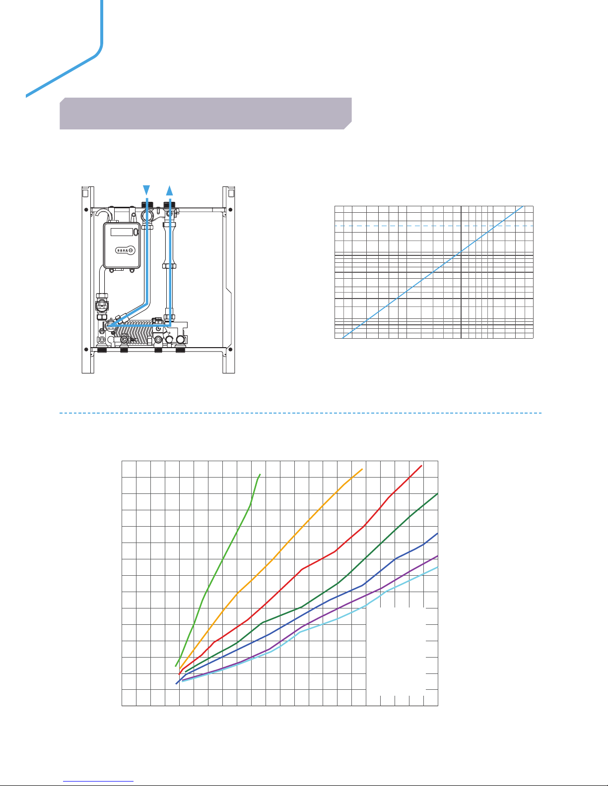
PRIMARY FLOW CHARACTERISTICS
CHS
HRHF
Page 17

17
Primary Flow Rate I/h
Primary flow temperatures
1,500
1,400
1,200
1,000
800
600
400
200
0
0 100 200 300 400 500 600 700 800 900 1,000 1,100
Domestic Hot Water Flow Rate @ 48˚C - l/h
55˚C
60˚C
65˚C
70˚C
75˚C
80˚C
85˚C
Primary flow temperatures
55˚C
60˚C
65˚C
70˚C
75˚C
80˚C
85˚C
Primary flow temperatures
55˚C
60˚C
65˚C
70˚C
Primary flow temperatures
temperatures
DOMESTIC HOT WATER OUTPUT
Page 18

18
* After shut-off valves are installed the connections become a female 3/4’’.
** Not shown on components illustration.
CONNECTION A B C
Thread G¾” G½” G1”*
D E F Depth inc. Cover kg
65mm 450mm 550mm 265mm 16
• Single plate design hydraulically separates the domestic
water with the space heating supplied directly from the
central primary supply
• Internal electronic control unit with LCD display
• Compact and lightweight
• Fully insulated EPP front cover
• Includes differential pressure control valve (DPCV)**
supplied and fitted to the base of the unit
• Ability to pre-heating of the DHW exchanger
FEATURES & BENEFITS
The Logic heat interface unit is the latest
‘intelligent’ range of Logic HIUs from Ideal.
The Logic HIU is the complete solution for
instantaneous hot water production and space
heating control.
This is a direct wall mounted HIU, providing 50
kW indirect instantaneous priority Domestic
Hot Water (DHW). Central Heating (CH) is
dependent upon the primary system design
and pump specification.
LOGIC HIU
50 DIRECT HIGH TEMP
F
AB
D
E
D
A B
D
C
C
Page 19

19
Maximum working pressure: 10 bar
Maximum temperature 85°C
Max. Percentage of glycol 30%
Max. Recommended primary
circuit flow rate
1.2 m³/h
PRIMARY PERFORMANCE
Heat Interface Unit HT
Primary ball valve set
Central heating flow & return valves
DHW inlet and outlet connection valves
Differential pressure control (DPC)
UIN PRODUC T NAME METERING OPTIONS
211096 Logic HIU Direct HT
HIU only, meter not
included
211349 Logic HIU Direct HT
Factory fitted, CF Echo 11
MbBus 1
211353 Logic HIU Direct HT
Factory fitted, CF
Ultramaxx V MBus PS
Power supply 230 V (ac)±10% 50 Hz
Max. Power consumption 105 W
Protection class IP 40
Actuator Stepper 24 V
Probes NTC 10 kΩ
ELECTRICAL
Frame RAL 9010 sprayed steel
Protective shell cover EPP (Expanded polypropylene)
Components Brass BS EN 12165 CW617N
Pipes Stainless steel
Exchanger Brazed stainless steel
CONSTRUCTION
INCLUDED AS STANDARD
The temperature setting operates on the principle of set
point regulation and can be fixed within application limits.
HEATING
The DHW function takes priority over the heating function
controlled by the DHW priority flow switch.
DOMESTIC HOT WATER - DHW
INCLUDING OPTIONAL PRE HEAT FUNCTION
Flushing By-pass
CF Echo II
CF Ultramaxx V
ACCESSORIES
Heating Set Point Dependent on primary system
Nom. heating exchanger net
output
As primary and heating circuit
controls permit
Heating circuit Maximum pressure rating: as
primary and heating circuit
controls permit
Heating control circuit VOLT FREE
Set Point DHW temperature 42 to 60°C
Max. Domestic hot water
pressure
10 bar
DHW circuit max. flow rate 18 l/m (0.3 l/s)
Min. flow rate to activate
domestic flow sensor
2.7 l/m ±0.3
Max. Differential pressure on
domestic water modulating
valve
Δp 0.9 bar
Min. Differential pressure on
domestic water modulating
valve
Δp 0.35 bar
Nom. DHW heat exchanger
net output
50 kW - Logic HIU 50 Direct
HT
Page 20
20
Primary Flow Rate I/h
Primary flow temperatures
1,500
1,400
1,200
1,000
800
600
400
200
0
0 100 200 300 400 500 600 700 800 900 1,000 1,100
Domestic Hot Water Flow Rate @ 48˚C - l/h
55˚C
60˚C
65˚C
70˚C
75˚C
80˚C
85˚C
Primary flow temperatures
55˚C
60˚C
65˚C
70˚C
75˚C
80˚C
85˚C
Primary flow temperatures
55˚C
60˚C
65˚C
70˚C
Primary
flow
temperatures
temperatures
DOMESTIC HOT WATER OUTPUT.
DHW - heat exchanger
0.04 0.06 0.08 0.1 0.2 0.3 0.4 0.5
0.04 0.06 0.08 0.1 0.2 0.3 0.4 0.5
Flowrate - l/s
50
10
1
0.5
20
30
2
3
5
Pressure loss - kPa
Kv = 2.25 m³/h
Hydraulic Characteristics
Heating - secondary side
Flow Path
Heating - secondary side
ONON DHWDHWCHCHFAFAULULTT
RRESETESET
11
22
CHS
0
10
20
30
40
50
60
0 0.1 0.2 0.3 0.4 0.5 0.6
Flowrate -l/s
Pressure loss -kPa
3
2
1
Kv = 2.63 m³/h
UPS 15 - 60 pump settings
ONON DHWDHW CHCH FAFAULULTT
RRESETESET
11
22
CHS
HRHF
DHW - heat exchanger
Flowrate - l/s
50
10
1
0.5
20
30
2
3
5
Pressure loss - kPa
Kv = 2.03 m³/h
Flow Path
Heating - primary side
ONON DHWDHW CHCH FAFAULULTT
RRESETESET
11
22
HR
HF
CHS
HYDRAULIC CHARACTERISTICS DOMESTIC HOT WATER - PRIMARY SIDE
DOMESTIC HOT WATER
PRIMARY FLOW CHARACTERISTICS
CHS
Page 21

21
• RHI compliant
• Ultrasonic pulse measurement
• MID certified (Measuring instruments directive)
• MBus + 1 water meter
CF ECHO II
FLUSHING BYPASS
SALES CODE 211097
FLUSHING BYPASS:
• Connects to primary flow on boiler plant side
• Enables main system pipework to be flushed
and cleaned whilst HIU remains isolated
• Blanking ports as standard to allow for
measuring differential pressure
(test points required)
ACCESSORIES
MODEL METER SALES CODE
Logic HIU 75 Indirect
Factory fitted
CF Echo 11 MBus 1
211346
Logic HIU 50 Indirect 211347
Logic HIU 50 Direct MT 211348
Logic HIU 50 Direct HT 211349
• RHI compliant
• Ultrasonic pulse measurement
• MID compliant (Measuring instruments directive)
• MBus PS
CF ULTRAMAXX V.
MODEL METER SALES CODE
Logic HIU 75 Indirect
Factory fitted CF
Ultramaxx V MBus
PS
211350
Logic HIU 50 Indirect 211351
Logic HIU 50 Direct MT 211352
Logic HIU 50 Direct HT 211353
METERING &
ACCESSORIES
Page 22
CONDENSING
COMMERCIAL
BOILERS
Page 23
23
EVOMAX
30 - 150kW
Available in outputs of 30, 40, 60, 80, 100, 120 and 150kW, the
Evomax is designed to ensure all installation requirements can be
achieved. There is also an LPG Evomax range from 30 - 80 kW for
off mains installations.
• 5 year warranty*
• Robust & light aluminium silicon alloy
heat exchanger
• Up to 110% part load efficiency
• High 5:1 turndown
• Compact – one width & height for easy siting
• Simple controls interface with large
backlit display
• Comprehensive range of flue, fixing and
control options
• Designed for easy installation, commissioning
and servicing
• Proven reliability through design, component
selection and proving
• NOx <40mg/kWh (Class 5) for all natural gas
models for maximum BREEAM points
FEATURES & BENEFITS
*5 year warranty subject to Terms and Conditions. 5 years parts and labour warranty available subject to being commissioned by Ideal Boilers.
DOWNLOAD
THE APP
Page 24
24
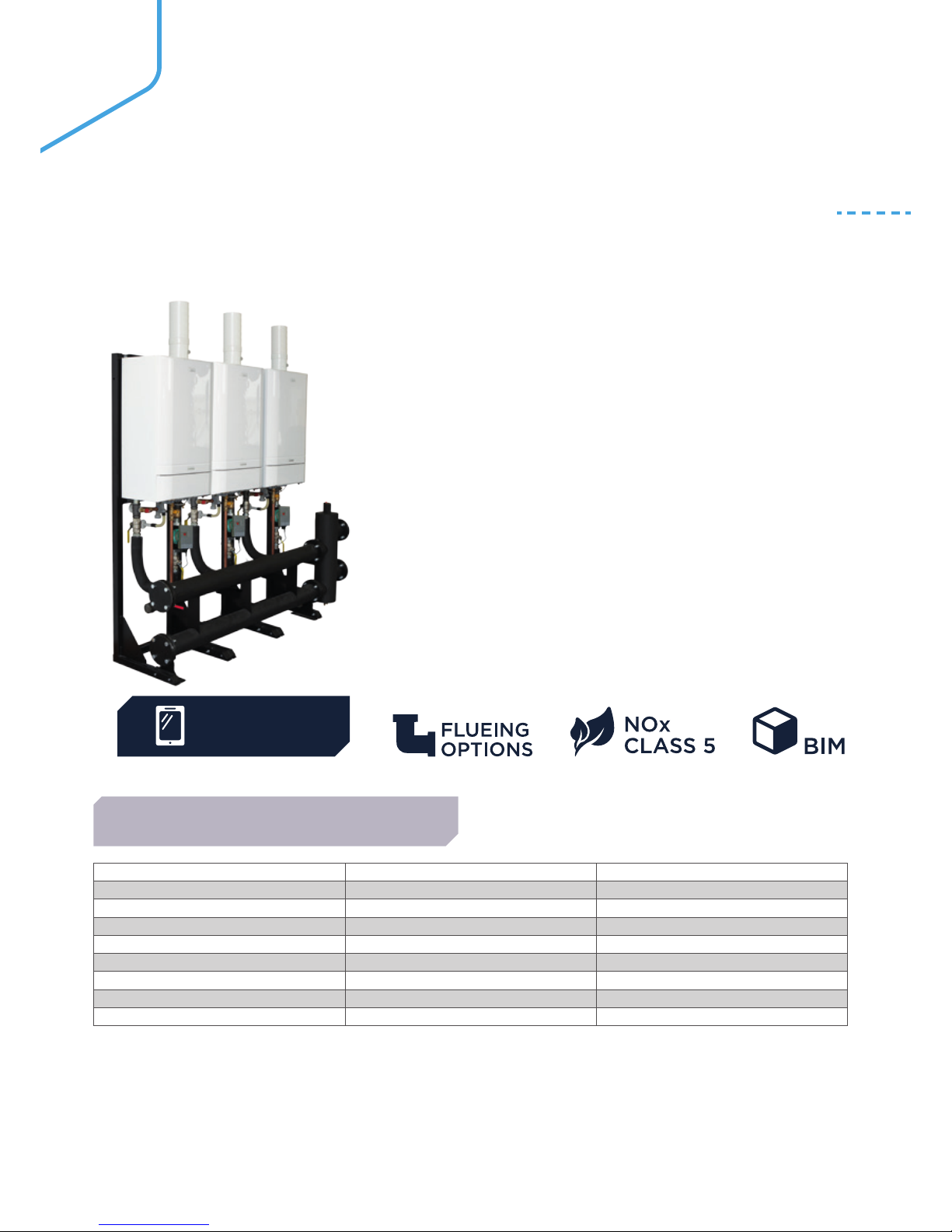
EVOMAX CASCADE
FRAME & HEADER KITS
BOILER FRAME AND HEADER KITS
The Frame and Header Kits are suitable for modular (cascade) boiler
installations, and are available up to a maximum output of
600 kW, in both in-line and back-to-back arrangements.
IN-LINE KITS
Kits include flow & return headers with mixing header and gas
header, all with fixing brackets. For easy connection flexible stainless
steel pipe and connections are supplied together with pressure relief
valves, boiler shut off valves and drain cock.
Appropriately sized ErP modulating shunt pumps are also included.
Flow, return and low loss headers together with the flexible boiler
connections are all pre insulated. Separate single boiler frame kits
are available for use with in-line kits if required.
BACK-TO-BACK KITS
Kits include all the in-line contents plus the required special frame
kits for such compact installations. Both types of kit are available
for the following number of boilers and sizes. Mixing header kits and
modulating pump kits are also available separately.
In-line kits do not include the support frame as the boilers can be wall mounted, but a frame kit is
available if the wall is unsuitable to facilitate boiler mounting.
For full details of all configurations & specifications, please refer to the installation manual.
2 boilers 30-100 DN80
2 boilers 120-150 DN80
3 boilers 30-100 DN80
3 boilers 120-150 DN100
4 boilers 30-100 DN100
4 boilers 120-150 DN100
5 boilers 30-100 DN100
5 boilers 120 DN100
6 boilers 30-100 DN100
Please note, the Evomax boilers are to be ordered separately.
AVAILABLE OPTIONS
DOWNLOAD
THE APP
Page 25
25
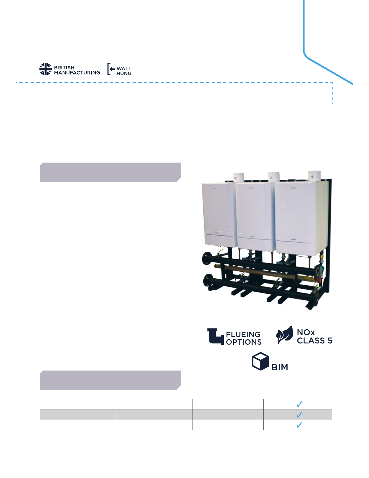
LOW HEIGHT FRAME & HEADER KITS
BOILER FRAME AND HEADER KITS
The Low Height Frame and Header Kits make installation much simpler in circumstances of reduced headroom,
offering an option of replacing a floor standing atmospheric boiler with a high efficiency model.
Three options are available allowing for outputs from 30 kW to 450 kW.
• Frame and Header Kits fit easily through
standard doorways
• Lift weights are as low as possible
• The Low Height Frame and Header Kit is supplied on one
palette shrink wrapped together with all ancillary fittings
needed for assembly
• All pipe work connections are supplied with either the
boiler, header kit or are pre assembled to the header kit
• Pre assembled to header; the boiler the flow and return
flexible connections, which reduce installation time
• Delivered with header kit; connection pipe assembly, non
return valves & pipe work connector, all isolation valves,
pressure relief valve, drain cock and associated fittings
• The Low Height Frame and Header Kit can be installed
with either an Ideal Commercial Sequencer offering direct
modulation of the system, reducing running costs, or a
proprietary option
• The extremely compact dimensions allow for replacement
of existing standard efficiency floor standing boilers,
using a single wall mounted condensing boiler up to 150
kW allowing sufficient space to install flue system, pump
and pipe headers
• High quality and well-finished components
• Supplied with frames and low energy modulating pumps
(ErP approved)
FEATURES & BENEFITS
AVAILABLE OPTIONS
1 Boiler 30-150 DN50 (2”BSP)
2 Boiler 60-300 DN65
3 Boiler 90-450 DN80
Page 26

26
IMAX XTRA
80 - 280kW
The Imax Xtra range of condensing boilers is offered in six models with
outputs from 80 to 280 kW suitable for floor standing application in
either single or multiple applications.
• Robust cast aluminium silicon alloy heat exchanger
• In-built commissioning and fault diagnostics
• Volt free contacts and BMS operation standard
• Meets Building Regulations (Part L2)
• Compact size - small footprint
• High 5:1 turndown
• Up to 107.5% net efficiency (fully condensing)
• Fits through standard doorways
• Conventional or room sealed flue options
• Direct weather compensation option
• NOx <40mg/kWh (Class 5) for maximum
BREEAM points
• 2 year parts and labour warranty
FEATURES & BENEFITS
DOWNLOAD
THE APP
Page 27

27
IMAX XTRA EL
320 - 1240kW
The Imax Xtra EL range of condensing boilers is available in 10
models with outputs from 320 to 1240kW. Suitable for floor standing
applications in either single or multiple installations.
• Simple control interface with large backlit display
• Volt free contacts
• 0-10V BMS operation standard
• Robust aluminium silicon alloy heat exchanger
• Suitable for single or multiple installations
• Up to 109.8% part load at 30% output
• 2 year parts and labour warranty
• NOx <40mg/kWh
• Natural Gas
• ErP compliant (320 - 395kW)
• Building Regulation Part L2 compliant
(470 - 1240kW)
FEATURES & BENEFITS
DOWNLOAD
THE APP
Page 28
28
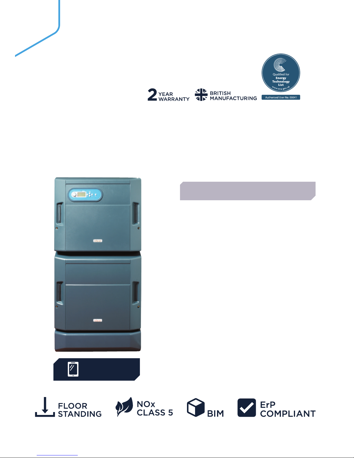
EVOMOD
250 - 1000kW
Available in 250, 500, 750 and 1000 kW modules, the Evomod will achieve
an output up to 1MW from a single unit solution together with a minimum
footprint that enables the product to be installed where space is limited. Each
module provides a maximum of 250 kW heat output and will modulate down
through a sophisticated control system.
• Modules up to 3 high stacking
• Stainless steel heat exchanger
• Built in module diagnostics, sequencing and
remote indication
• Plain text display for fast and easy use
• Single flue outlet, system, gas and
electrical connections
• Up to 20:1 turndown: 1MW boiler can modulate
down to just 46.7kW
• Easy access for servicing
• Minimum footprint with easy site handling and
standard doorway access allowing simplified
plant replacement
• NOx <40mg/kWh (Class 5) for maximum
BREEAM points
• 2 year parts and labour warranty
• Up to 108.5% net efficiency (fully condensing)
• Single boiler control for all module options
FEATURES & BENEFITS
DOWNLOAD
THE APP
Page 29

29
EVOJET
150 - 1450kW
The Evojet condensing range of pressure jet boilers are available in
10 models with outputs from 150-1450kW. Floor standing boilers for
applications in either single or multiple configurations.
• Up to 109.3% part load efficiency
• Designed to operate up to 40°C ΔT providing
minimum flow rates are achieved
• Dedicated low temp return
• Stainless steel heat exchanger
• Natural gas, LPG, oil and dual fuel models
• Triple flue pass for high operating efficiencies
• Natural gas/LPG burner options - modulating or
high / low operation
• Modulation via 0-10 volt BMS, or RWF controller
FEATURES & BENEFITS
DOWNLOAD
THE APP
Page 30

3030
VANGUARD L
420-7000kW
• Steel Shell and Tube
• Floor Standing
• Range of matched burners
VICEROY GTS
450-780 kW
• Cast Iron heat exchanger
VISCOUNT GTS
754-1450 kW
• Cast Iron heat exchanger
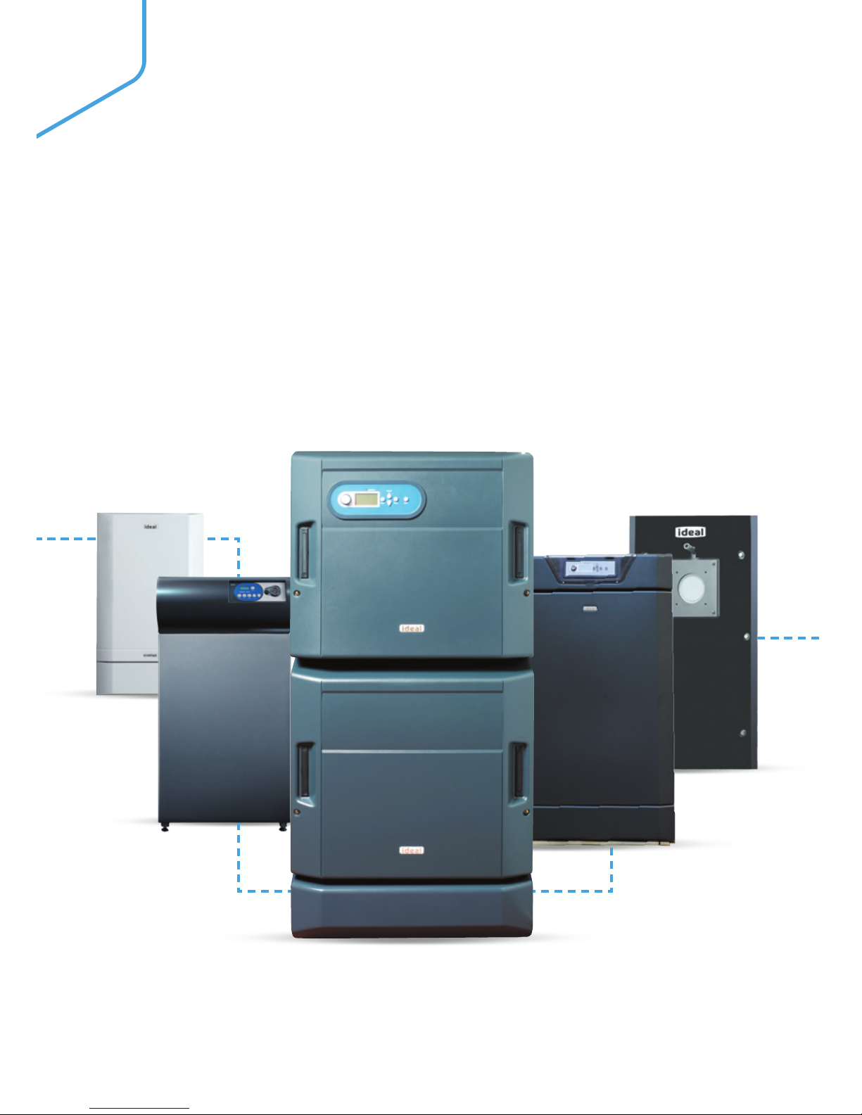
CONDENSING BOILERS
PRESSURE JET BOILERS
EVOMAX
• Wall Hung
• Aluminium
Alloy Heat
Exchanger
• 30-150 kW
• 30-80kW LPG
IMAX XTRA
• Floor Standing
• Aluminium
Alloy Heat
Exchanger
• 80-280 kW
EVOMOD
• Floor Standing
• Stainless Steel
Heat Exchanger
• Modular
• 250-1000 kW
EVOJET
• Floor Standing
• Stainless Steel
Heat Exchanger
• 150-1450kW
• Condensing
Pressure Jet
• Natural Gas, LPG,
Oil or Dual Fuel
IMAX XTRA EL
• Floor Standing
• Aluminium
Alloy Heat
Exchanger
• 320-1240 kW
COMMERCIAL RANGE OVERVIEW.
Page 31
3131
• Indirect 50 & 75 units with twin plate design
• Direct 50 MT & HT units with single plate design
• Light weight and compact
• Ultrasonic metering options available
MODELS AVAILABLE:
LOGIC HIU 50 INDIRECT
LOGIC HIU 75 INDIRECT
LOGIC HIU 50 DIRECT
MEDIUM TEMP. (MT)
LOGIC HIU 50 DIRECT
HIGH TEMP. (HT)
The Ideal Heat Interface Units are heat energy transfer
units. Designed for use in conjunction with centralised
boilers, district heating or central energy systems. The
function is to efficiently transfer heat from the plant
room to the individual dwelling’s central heating (CH)
and domestic hot water (DHW) systems.
HEAT INTERFACE UNITS (HIU)
TYPICAL SYSTEM
DOWNLOAD
THE APP
Page 32

32
Page 33

33
Page 34

Page 35

3535
At Ideal, we are committed to delivering the highest
levels of customer service. With over a century of
experience in the heating industry, we know how
important confidence and trust is to our customers.
NEED HELP?
BOILER TRAINING
GET IN TOUCH WITH US TODAY
WE’VE GOT TRAINING COVERED
You can be confident to know that you’re partnering with a British manufacturer
that’s supported by a dedicated national service team, delivering help and
advice to you and your customers throughout the year.
SALES
Tel: 0844 5436060
Fax: 0844 5436181
TECHNICAL
Tel: 01482 440237 Fax: 01482 498621
commercial.services@idealboilers.com
BOOK ONLINE AT:
idealcommercialboilers.com
Our comprehensive one-day courses can be mixed and matched for individual
installation and servicing companies. Each course uses a simple step-bystep approach with hands on training to ensure all aspects of commissioning,
servicing, and fault finding can be dealt with quickly and efficiently.
HERE FOR YOU.
Page 36

211345 08.17
P.O. Box 103, National Avenue
Kingston Upon Hull, HU5 4JN
T: 0844 5436060
F: 0844 5436181
APPROVAL
These appliances are certified to G.A.D. 90/396 and B.E.D. 92/42 Safety and Performance Directives for gas boilers.
Ideal Commercial Boilers pursues a policy of continuous improvement in design and performance of its products and
reserves the right to vary specification without notice. Statutory rights of the consumer are not affected.
PLEASE NOTE:
The information in this brochure was correct at the time of going to print. Ideal Commercial Boilers reserve the
right to make any modifications to product specifications or any other details, without prior notification. For further
clarification, please enquire in writing to the head office address (address below).
 Loading...