

Page 1
0
LanTEK® II Series Manual
Page 2

LanTEK®II Cable Certifier Instruction Manual
This instruction manual contains information proprietary to IDEAL INDUSTRIES, INC. The
information in this document is not to be used or duplicated in any manner without prior
written approval from IDEAL INDUSTRIES, INC.
IDEAL INDUSTRIES, INC. and the IDEAL INDUSTRIES, INC. logo are registered trademarks of
IDEAL INDUSTRIES, INC.
All other product names mentioned in this manual are trademarked or copyrighted by their
respective manufacturers.
IDEAL INDUSTRIES, INC.
9650 Chesapeake Drive
San Diego, CA 92123
Phone: (800) 854-2708
Phone: (858) 627-0100
Fax: (858) 715-7003
Manual Part No.: P-2877 Rev. B
© 2009 IDEAL INDUSTRIES, INC. 2009-12
1
Page 3

Standard Warranty Policy of IDEAL INDUSTRIES, INC.
The General Terms and Conditions of the local subsidiary of IDEAL INDUSTRIES, INC. apply.
Safety Precautions
Exercise caution when handling rechargeable batteries (accumulators)
All lithium-ion battery packs (Li-ion), regardless of their indicated charge state, are capable of
producing electrical current sufficient to cause personal injury and/or property damage.
Do not dispose of lithium-ion battery packs (Li-ion) in a fire or with regular waste. Lithiumion battery packs (Li-ion) may explode if exposed to open flame. The battery packs are
hazardous waste and may contaminate ground water sources if disposed of in landfills.
IDEAL INDUSTRIES, INC. tries to provide the maximum protection possible by installing an
automatic reset fuse in the battery packs, to help stop high current discharge as quickly as
possible. However, these fuses may not completely protect against a momentary arc
discharge, which can result if the battery pack's electrical contacts are shorted. The following
battery pack handling precautions must be closely followed to avoid risk of injury.
When a battery pack is not installed in the Display (DH) or Remote (RH) handset, it
should be kept in a clean, dry, non-conductive package.
Keep conductive materials away from the battery pack at all times.
Keep contact sides of the battery pack away from each other at all times.
Battery packs can be charged while in the Display (DH) and in the Remote (RH) handset,
but also externally with the adapter. Charging in any other manner may cause the battery
pack to explode.
Always install, remove, store, and charge the battery packs in a non-explosive
atmosphere.
Observe operating and storage temperatures (see chapter 1.3. Dimensions, Weights,
Operating Conditions).
Do not allow children or persons unfamiliar with the precautionary instructions in this
manual to handle or recharge the battery packs.
Do not open the battery pack case. There are no user-serviceable parts inside the case,
and the batteries in the case are not replaceable.
2
Page 4

Disclaimer
WARNING!
This symbol indicates potentially lethal voltages. The life
and/or health of the person performing the activity or anybody
in the vicinity is at risk.
CAUTION!
This symbol indicates that the relative activity could possibly
harm the environment or damage technical equipment.
NOTE:
Here you will find general notes, additional information, or
support.
Boldface
Refers to a button on LanTEK®II Cable Certifier.
Italics
Refers to a menu option in this Operating Manual.
Quotation marks " "
Identifies a "Screen Message".
IDEAL INDUSTRIES, INC. does not assume any liability for death, injury or damage to
equipment or property resulting from improper use of the battery packs.
IDEAL INDUSTRIES, INC. will not be liable for consequential damages that may result from
tampering with the battery packs or charger or their use thereafter.
Subject to technical changes.
Environmental Protection
If you have any questions concerning these precautions, the operating instructions, or any
other concerns about the safe use and disposal of the battery packs used in LanTEK®II, please
contact a representative of IDEAL INDUSTRIES, INC. For contact information, please refer to
Chapter Customer Service.
Using the LanTEK®II Cable Certifier
All cable parameter default settings programmed in the LanTEK®II Cable Certifier are based
on generic standards, proposed industry recommendations for cables and network links, the
latest technical information available from International LAN cabling standards committees,
the LAN industry, and IDEAL INDUSTRIES' own experience and testing.
Before performing any measurements, IDEAL INDUSTRIES, INC. recommends to request
detailed information from contractor or project manager on the standards to be used for
measuring, to ensure that relevant parameters are complied with.
Information on the use of this Instruction Manual
The following symbols used in this manual indicate that the user should exercise particular
caution in order to prevent personal injury or damage to the LanTEK®II Cable Certifier or the
system under test.
Typographical Conventions
3
Page 5

Table of contents
CHAPTER 1 Your LanTEK®II Cable Certifier................................................. 9
1.1. Technical Information ...................................................................................... 9
1.2. Product Specifications .................................................................................... 10
1.3. Dimensions, Weights, Operating Conditions ...................................................... 10
1.4. Performance Specifications ............................................................................. 11
CHAPTER 2 Product Description ............................................................... 12
2.1. The Display Handset (DH) .............................................................................. 12
2.1.1. Controls and Ports/Connectors ........................................................................ 12
2.1.2. TFT Display .................................................................................................. 14
2.1.3. Function Keys F1 to F10 ................................................................................. 15
2.1.4. Soft Key ....................................................................................................... 15
2.2. The Remote Handset (RH)............................................................................... 16
2.2.1. Controls and Ports/Connectors ........................................................................ 16
2.3. Power Management ....................................................................................... 18
2.3.1. Operating the Display and Remote handset from AC Power ................................ 18
2.3.2. Battery Charging ........................................................................................... 19
2.4. Talkset ........................................................................................................ 19
CHAPTER 3 Basics of the Cable Test ......................................................... 20
3.1. Testing of cables and relevant requirements ..................................................... 20
3.1.2. Setup for Permanent Link Test ........................................................................ 20
3.1.3. Setup for Channel Link Test ............................................................................ 20
CHAPTER 4 Preferences............................................................................ 21
4.1. Open Preferences .......................................................................................... 21
4.2. Language ..................................................................................................... 21
4.3. User Information........................................................................................... 22
4.4. Autotest Options ........................................................................................... 22
4.5. Contrast ...................................................................................................... 23
4.6. Timeout Options ........................................................................................... 23
4.7. Measurement Units ....................................................................................... 24
4.8. Talkset ........................................................................................................ 25
4.9. Date and Time .............................................................................................. 25
4.10. Restore Default ............................................................................................. 26
4.11. Clear Memory ............................................................................................... 27
4.12. Temperature ................................................................................................ 27
CHAPTER 5 Autotest ................................................................................. 28
5.1. Set Autotest Pref ......................................................................................... 29
5.2. Select Job Folder.......................................................................................... 30
5.2.1. Enable Existing Job Folder ............................................................................. 30
5.2.2. Create New Job Folder .................................................................................. 31
5.3. Set Cable Name (cable ID) ............................................................................ 33
5.3.1. Simple Cable ID ........................................................................................... 34
4
Page 6

Table of contents
5.3.2. Default Cable ID .......................................................................................... 35
5.4. Labeling Standard TIA/EIA 606-A ................................................................... 37
5.4.1. Cable Name in Format TIA/EIA 606A .............................................................. 38
5.4.2. Cable Parameter 606A Drop .......................................................................... 38
5.4.3. Cable Parameter 606A Backbone .................................................................... 39
5.4.4. Cable Parameter 606A Backbone Pair/Fiber ..................................................... 39
5.5. Select Twisted Pair Cabling............................................................................ 40
5.5.1. Specify Cable Type ....................................................................................... 41
5.5.2. Create Cable Type ........................................................................................ 41
5.5.3. Edit and Calculate NVP .................................................................................. 44
5.5.4. Enter Reference Temperature ........................................................................ 45
5.6. DualMODE™ Function for Twisted Pair Cabling ................................................. 46
5.6.1. Implement DualMODE™ ................................................................................ 46
5.7. Edit NVP Default Value of a Cable ................................................................... 47
5.8. Coaxial Cable Standards ............................................................................... 48
5.8.1. Autotest Test Series for Coaxial Cables ........................................................... 49
5.9. Calibration .................................................................................................. 50
5.9.1. Twisted Pair Cabling ..................................................................................... 50
5.9.2. Coaxial Cable ............................................................................................... 52
5.10. Perform Autotest .......................................................................................... 53
5.11. Open Job Folder of Autotest ........................................................................... 53
5.11.1. Job Options ................................................................................................. 53
5.11.2. Test Options ................................................................................................ 53
5.11.3. Copy Job Folder to USB Removable Storage .................................................... 54
5.11.4. Alien Crosstalk Measurements (AXT) ............................................................... 54
5.12. Autotest Results and Graphs .......................................................................... 54
5.12.1. Graph Formats, Layouts and Controls ............................................................. 56
CHAPTER 6 Structured Cabling Testing .................................................... 58
6.1. Test Setup for Single Test Analysis .................................................................. 58
6.2. Test Run of Single Test Analysis...................................................................... 58
6.3. Perform Single Test Analysis .......................................................................... 58
6.4. Evaluation of Analysis Test Results .................................................................. 59
6.4.1. Graphs for Analysis Tests ............................................................................... 59
6.5. Overview of Single Test Analysis ..................................................................... 59
6.6. Wiremap Test ............................................................................................... 60
6.7. Length Test .................................................................................................. 61
6.7.1. Length Test Error .......................................................................................... 61
6.8. Resistance Test............................................................................................. 61
6.8.1. Resistance Test Error ..................................................................................... 61
6.9. NEXT, ACR-F (ELFEXT) and Power Sum............................................................ 61
6.10. Power Sum NEXT, Power Sum ACR-F (ELFEXT) ................................................ 62
6.10.1. NEXT Test and ACR-F (Power Sum ELFEXT) Test Error ...................................... 63
6.11. Insertion Loss Test (Attenuation) ................................................................... 64
5
Page 7

Table of contents
6.11.1. Insertion Loss test Error ................................................................................ 64
6.12. Return Loss Test .......................................................................................... 64
6.12.1. Return Loss Test Error .................................................................................. 64
6.13. Impedance Test ........................................................................................... 65
6.13.1. Impedance Error .......................................................................................... 65
6.14. Delay and Skew Test .................................................................................... 65
6.14.1. Delay and Skew Test Error ............................................................................ 66
6.15. Capacitance Test .......................................................................................... 66
6.15.1. Capacitance Test Error .................................................................................. 66
6.16. ACR-N (ACR) Test and Power Sum ACR-N (Power Sum ACR) Test ...................... 66
6.16.1. ACR-N (ACR) Test and Power Sum ACR-N (Power Sum ACR) Test Error .............. 67
6.16.2. Troubleshooting ACR-N (ACR) Test and Power Sum ACR-N (Power Sum ACR) ..... 67
6.17. Headroom Test ............................................................................................ 67
6.17.1. Headroom Test Error .................................................................................... 67
6.18. Custom Cable Preferences and Cable Parameters ............................................. 68
6.18.1. Creating a New Customs Cable Type ............................................................... 68
6.18.2. Select Custom Cable Type ............................................................................. 69
6.18.3. Custom Cable Parameters ............................................................................. 69
CHAPTER 7 Coaxial Cable Test .................................................................. 71
7.1. Properties of Coaxial Cables ........................................................................... 71
7.2. Troubleshooting Coaxial Cables ....................................................................... 71
CHAPTER 8 Fiber Testing with FiberTEK™ FDX ......................................... 72
8.1. Safety Precautions ........................................................................................ 72
8.2. Notes on Cleaning Measuring Adapter and Patch Cord ....................................... 72
8.3. Performance Specification .............................................................................. 73
8.4. Test Setup According to Reference Method with Three Test Cords ...................... 74
8.5. Test setup According to Reference Method with One Test Cord .......................... 74
8.6. Set Autotest Pref .......................................................................................... 75
8.6.1. Selection of Module (fiber type) ...................................................................... 75
8.6.2. Determine Loss Budget .................................................................................. 75
8.7. Calibration ................................................................................................... 77
8.8. Performing Calibration ................................................................................... 77
8.9. Evaluation of Autotest Results for Fibers (LWL) ................................................. 78
8.9.1. Passed/Failed Rating ..................................................................................... 78
8.9.2. Saving Current Autotest Results ...................................................................... 78
8.9.3. Manual Saving of Autotest Results (Autosave off) .............................................. 79
8.9.4. Working with Jobs ......................................................................................... 79
8.9.5. Display of Result Details ................................................................................ 79
8.10. FiberTEK™ FDX Measuring Mode .................................................................... 79
8.10.1. Continuous Run ............................................................................................ 80
8.10.2. Power Meter Mode ........................................................................................ 81
8.10.3. Set Reference Value ..................................................................................... 81
6
Page 8

Table of contents
8.10.4. Light Source Mode ........................................................................................ 81
8.11. Application-specific Configuration of a Fiber Test .............................................. 82
8.11.1. Determine Loss Budget ................................................................................. 82
8.11.2. Select Fiber Standard and Determine Loss Budget ............................................ 83
CHAPTER 9 Tone Generator ...................................................................... 86
9.1. Tone Generator ............................................................................................. 86
9.1.1. Enable Tone Generator with Display handset (DH) ............................................. 86
9.1.2. Enable Tone Generator with Remote handset (RH) ............................................. 87
CHAPTER 10 IDEAL DataCENTER Software .............................................. 88
10.1. Installing Software ....................................................................................... 88
10.1.1. System Requirements ................................................................................... 88
10.1.2. Start Installation .......................................................................................... 88
10.2. Select Language .......................................................................................... 89
10.3. Software-Update .......................................................................................... 89
10.3.1. Retrieve Version ........................................................................................... 89
10.3.2. Perform Update ............................................................................................ 89
10.4. Databases ................................................................................................... 90
10.4.1. Create a new database ................................................................................. 90
10.4.2. Open an existing database ............................................................................ 91
10.5. Transfer job file ........................................................................................... 92
10.5.1. Upload from LanTEK
10.5.2. Import from the computer or an external data carriers (USB Flash Drive) ............ 94
10.5.3. Export job folder .......................................................................................... 95
10.5.4. Rename job folder ........................................................................................ 96
10.6. Manage Tests .............................................................................................. 97
10.6.1. Edit information ........................................................................................... 97
10.6.2. Edit tests and test records ............................................................................. 98
10.6.3. Test details .................................................................................................. 98
10.6.4. Graphs ........................................................................................................ 99
10.7. Produce and print reports ............................................................................ 100
10.7.1. Set up header and footer ............................................................................ 100
10.7.2. Define test selection. .................................................................................. 101
10.7.3. Print ......................................................................................................... 101
10.8. Online Help ............................................................................................... 102
®
II Cable Certifier ............................................................ 92
CHAPTER 11 LANTEK Firmware Upgrade ............................................... 103
11.1. Perform Firmware Upgrade .......................................................................... 103
11.1.1. Using the Computer .................................................................................... 103
11.1.2. Firmware Upgrade with USB Removable Storage ............................................ 104
CHAPTER 12 Specifications ................................................................... 105
12.1. Fiber (LWL) ............................................................................................... 105
CHAPTER 13 Customer Service .............................................................. 107
7
Page 9

Table of contents
13.1. Technical Support ...................................................................................... 107
13.2. Service in the US ....................................................................................... 107
13.3. Service outside the US ................................................................................ 107
13.4. Internet .................................................................................................... 109
8
Page 10

9
CHAPTER 1
Your LanTEK®II Cable Certifier
Features
LanTEK®II-350
LanTEK®II-500
LanTEK®II-1000
Frequency range
350 MHz
500 MHz
1000 MHz
Cable specification CAT 3/ISO C,
CAT 5/ISO D, 5e/D new, 6/E
Cable specification CAT 6A/ISO E
A
Upgradeable
Cable specification ISO F, ISO FA
Upgradeable
Upgradeable
(LanTEK®II)
DualMODE™-tests
Test with patch cord
CAT 6 test storage capacity with
graphs
1700
1700
1700
USB port
Serial port (concerns only Service)
Fiber (LWL) loss and length
measurement (FiberTEK™ FDX )
Optional
Optional
Optional
Communication over fiber (LWL)
and copper (Full Duplex)
LCD-display on Remote handset
(RH)
Tone generator to determine
connection on near and remote end
Lithium-ion battery packs
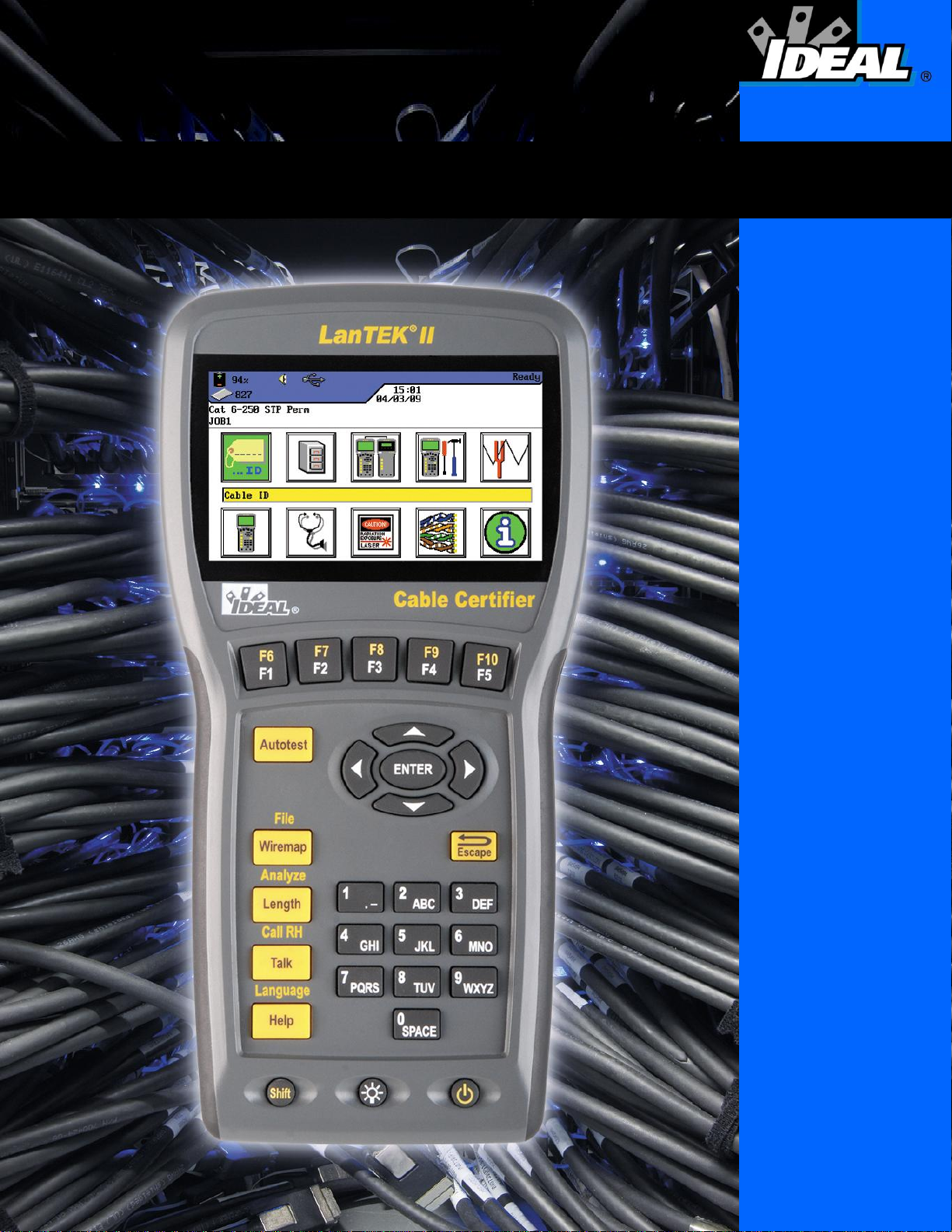
The LanTEK®II Cable Certifier is designed to measure twisted pair cables (TP), coaxial cables
and fiber-optic cables (LWL) used for high-speed data transmission in communications
networks.
1.1. Technical Information
Accuracy level
IV (ETL) IV (ETL) IV (ETL)
Page 11

Chapter 1
10
Your LanTEK®II Cable Certifier
1.2. Product Specifications
Standard Test Compliance
ANSI/TIA/EIA 568A, 568B, CAT 6A/6/5E/3, ISO FA/F/EA/D/C, AS/NZS 3080, IEEE 802.3
Ethernet, EN50173 – F/E/D/C
Cable Types
UTP/SCTP/FTP CAT 3/5E/6A/7 (100 Ω); Coax (50/75 Ω)
1.3. Dimensions, Weights, Operating Conditions
Dimensions:
(L) 254 mm x (W) 127 mm x (D) 53 mm
Weights:
Display handset (DH) 1180 g (incl. battery)
Remote handset (RH) 1120 g (incl. battery pack)
Battery pack 548 g
Battery Packs Display Handset (DH) and Remote Handset (RH):
Lithium-ion battery packs (Li-ion)
Operating life with Battery Pack:
18 hours under normal conditions
Charging Time:
In handset 6-8 hours
External 4 hours
Operating Temperature (min/max):
0o C to +50o C (Operate only if handset temperature is close to ambient temperature!)
Storage Temperature (min/max):
-20o C to +70o C
Relative Humidity:
5% to 90%, noncondensing
Page 12
11
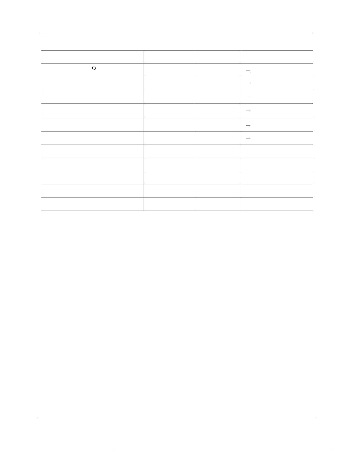
1.4. Performance Specifications
LanTEK
®
II
Range
Resolution
Accuracy
Length (50 - 100 cable)
0 – 605 m
0.1 m
+ (3 % + 1 m)
Delay
0 - 8000 ns
1 ns/0.1 m
+ (3 % + 1 ns)
Average impedance
35 – 180
0,1
+ (3 % + 1 )
Capacitance (bulk)
0 - 100 nF
1 pF or 3
digits
+ (2 % + 20 pF)
Capacitance
0 - 333 pF/m
0.1 pF
+ (2 % +1 pF)
DC loop resistance
35 -200
0,1
+ (1 % + 2 )
Attenuation
1 MHz - 1 GHz
0.1 dB
NEXT (crosstalk)
1 MHz - 1 GHz
0.1 dB
Return loss
1 MHz - 1 GHz
0.1 dB
ELFEXT / ACR-F
1 MHz – 1 GHz
0.1 dB
ACR / ACR-N
1 MHz – 1 GHz
0.1 dB
Chapter 1
Your LanTEK®II Cable Certifier
Level IV
Level IV
Level IV
Level IV
Level IV
Page 13
12
CHAPTER 2
Product Description
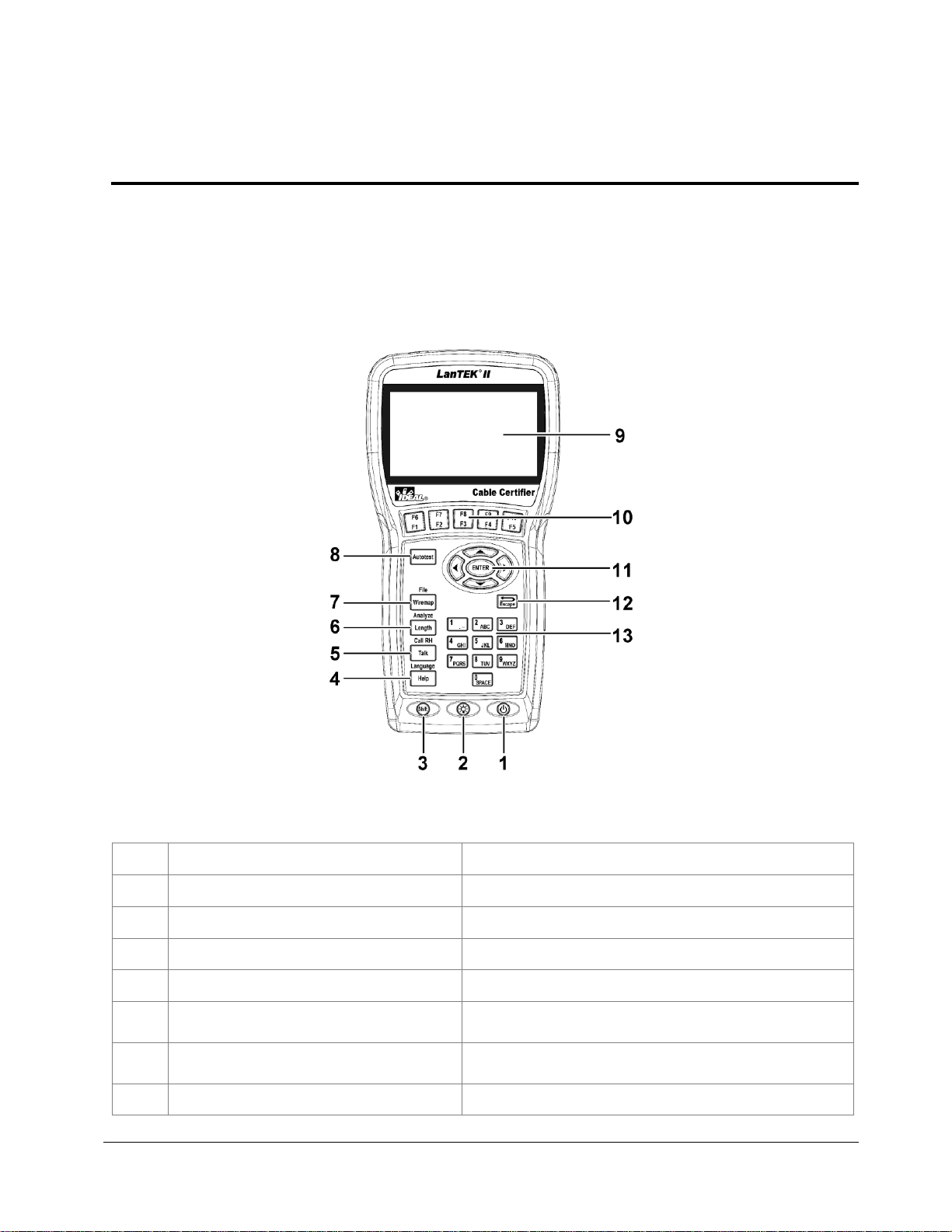
Controls
Description
1
On/Off
Power the Display handset (DH) on/off.
2
Dim Backlight
Dim Backlight in two stages.
3
Shift
Toggle key activities having dual functions.
4
Help / Language
Open Help Menu / Open Language Selection
5
Talk / Call RH
Activate Talkset function / call Remote Handset
(RH).
6
Length / Analyze
Open Length Measurement / Open Diagnostics
Menu.
7
Wiremap / File
Open analyze function "Wiremap" / Open Job List.
2.1. The Display Handset (DH)
The Display handset (DH) ensures control of preferences and test functions during individual
cable tests.
2.1.1. Controls and Ports/Connectors
Illustration 1 2.1. The Display Handset (DH)
Front view
Page 14
Chapter 2
13
Controls
Description
8
Autotest
Direct execution of test run pre-programmed for
established standards.
9
TFT-Display
Display of menus, test results, graphs, activity
selection and function keys.
10
Function keys
F1 to F5 / F6 to F10
Select menu options displayed on screen.
11
Arrow Keys / Enter
Navigate menus on TFT Display / Enter key to
activate and edit the selected menu.
12
Escape
Abort and exit the current menu without making
changes.
13
Alphanumeric Keys
Enter numbers, letters and special characters.
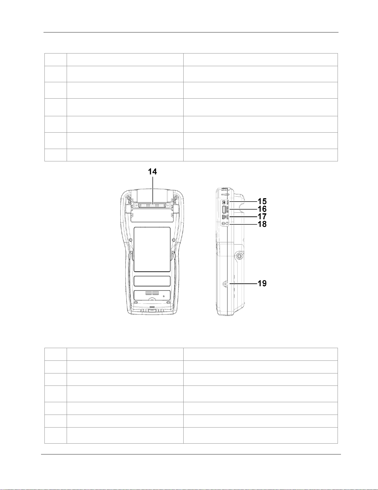
Ports/Connectors
Description
14
Low-NEXT-Connector
Connect a test adapter.
15
Service and Maintenance Jack
Connection for service and maintenance work.
16
USB Port
Connect USB removable storage to transmit data
and to load Firmware-Updates.
17
USB Device
Connect to a computer
18
Talkset Jack
Connect a Talkset.
19
DC Input Jack
Connect an external power supply and charge
battery pack.
Product Description
Illustration 2 2.1.1. The Display Handset (DH)
Rear and side view
Page 15
14
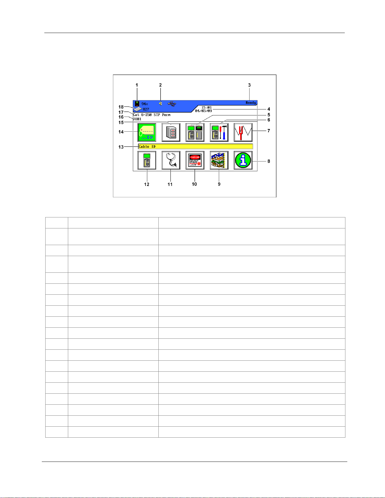
2.1.2. TFT Display
Display
Description
1
Power supply and charge
state
Indicates battery operation or external power supply and
charge state of battery pack (%).
2
Talkset indicator
Indicates whether talkset function is active.
3
Screen Title
Indicates that display handset (DH) or selected function is
ready.
4
Time and Date
Displays the time and date.
5
Field calibration
Select the field calibration.
6
Preferences
Select the instrument preferences.
7
Toner
Select the tone generator.
8
General Help
Select the Help menu.
9
Cable Type
Select or edit the cable type.
10
Fiber
Select the fiber measurement.
11
Analyze
Perform individual cable tests in real time.
12
Instrument
Display the information on LanTEK®II Cable Certifier.
13
Function Name
Displays the name of highlighted function.
14
Cable ID
Select cable naming function.
15
Stored Tests
Select file manager for the stored tests.
16
Job Name
Display the current job name.
17
Test Standard
Display the cable type selected for tests.
18
Records
Number of records stored.
Ready screen appears on operational Display handset (DH).
Illustration 2.1.2. TFT Display
Chapter 2
Product Description
Page 16
Chapter 2
15
Softkeys
Function keys
Product Description
2.1.3. Function Keys F1 to F10
Function keys F1 to F5 have dual functions (F6 to F10). Pressing down the Shift key while
simultaneously pressing one of the function keys F1 to F5 will activate the 2nd function of
the function key (example: Shift + F4 equals function F8).
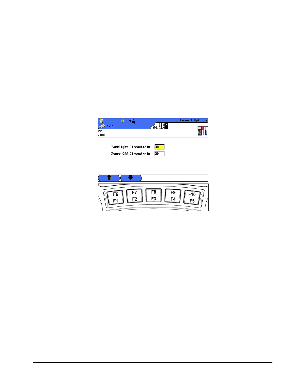
2.1.4. Soft Key
Soft keys indicate possible menu options at the bottom of the screen. To select the according
option, press the corresponding Function Key (F1 - F5) below the soft key.
The example below shows the setting of Timeout options by using the soft keys at the bottom
of the screen. The Value is set by Function Keys F1 (Increase) and F2 (Decrease).
Illustration 2.1. Soft keys and function keys
Page 17
Chapter 2
16
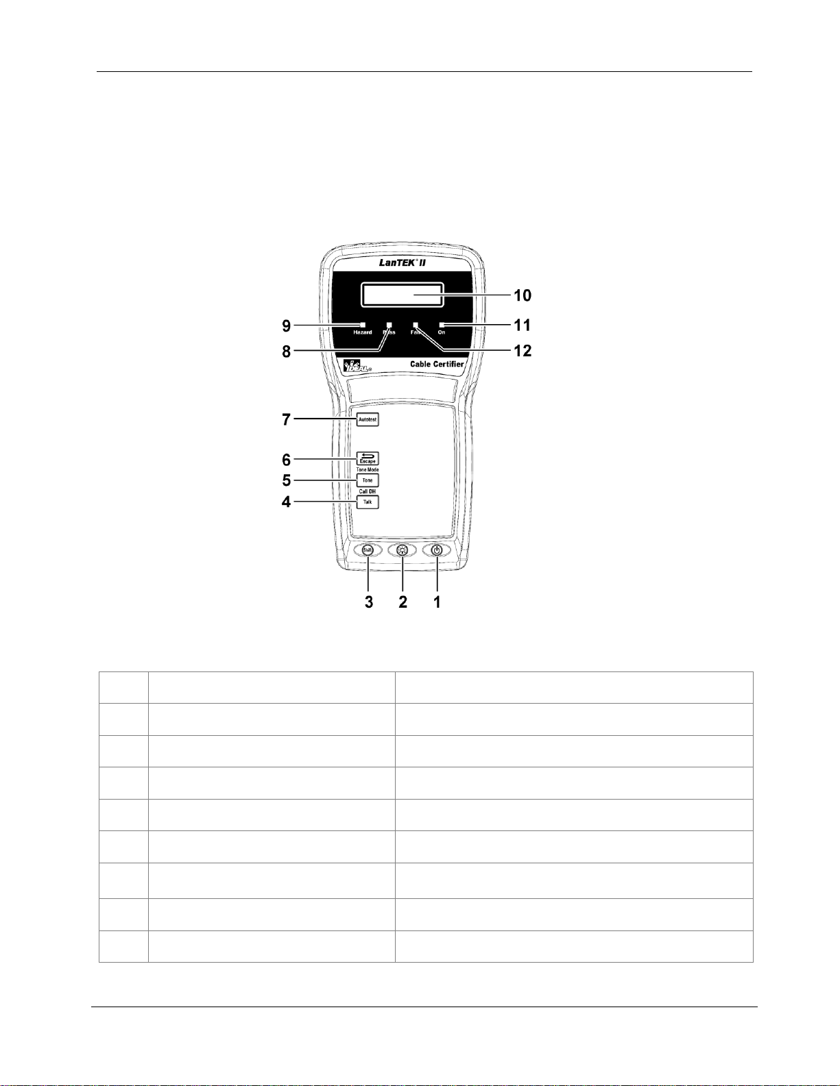
Controls
Description
1
On/Off
Power the Remote handset (RH) on/off.
2
Dim Backlight
Dim Backlight in two stages.
3
Shift
Toggle key activities having dual functions.
4
Talk / Call DH
Activate Talkset function / call Remote handset (RH).
5
Tone / Tone Mode
Power the tone generator on/off.
6
Escape
Abort and exit the current action without making
changes.
7
Autotest
Start the Autotest.
8
Pass LED
Test result: Passed.
Product Description
2.2. The Remote Handset (RH)
The Remote handset (RH) works with the Display handset (DH) to perform autotests or
individual real time analyze tests. The Remote handset (RH) is located at the end of the
cable link and communicates with the Display handset (DH). To perform measurements, the
Remote handset (RH) is automatically activated by the Display handset (DH).
2.2.1. Controls and Ports/Connectors
Illustration 2.2.1. The Remote Handset (RH)
Front view
Page 18
Chapter 2
17
Controls
Description
9
Hazard LED
Excessive line voltage (TELCO): Excessive voltage at
measurement input.
10
S/W-LCD Display
Two line alphanumeric display
11
On LED
The Remote Handset is on.
12
Fail LED
Test result: Fail.
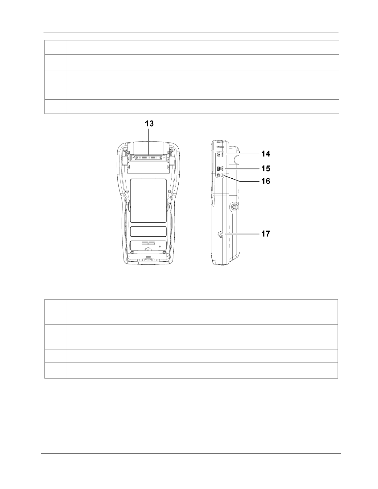
Ports/Connectors
Description
13
Low-NEXT-Connector
Connect a test adapter.
14
Service and Maintenance Jack
Connection for service and maintenance work.
15
USB Device
Connect to a computer for firmware updates.
16
Talkset Jack
Connect a Talkset.
17
DC Input Jack
Connect an external power supply and charge battery
pack.
Product Description
Illustration 1 2.2.1. The Remote Handset (RH)
Rear and side view
Page 19
Chapter 2
18
CAUTION!
Only the adapter provided with the instrument shall be used. Other types of adapters may
cause damage to the tester.
NOTE:
Do not connect to AC power when testing shielded cables, as this may result in ground
loops which in turn can cause input protection warnings.
Product Description
2.3. Power Management
Both the Display (DH) and Remote (RH) handset use interchangeable rechargeable lithiumion battery packs (Li-ion).
The Display (DH) and Remote (RH) handsets can be run on battery power for
approximately 18 hours. Actual battery power times depends on various factors, such as
operating time versus standby time, use of the display backlight, and ambient
temperature.
When charge state of battery drops below the required voltage, a warning appears. Tester
automatically shuts down before testing results are affected.
To save battery power, the Display (DH) and Remote (RH) handset automatically power
down after a certain period of inactivity.
If the instrument will not be used for a prolonged time it is recommended that the battery
protection strips be inserted to conserve battery charge.
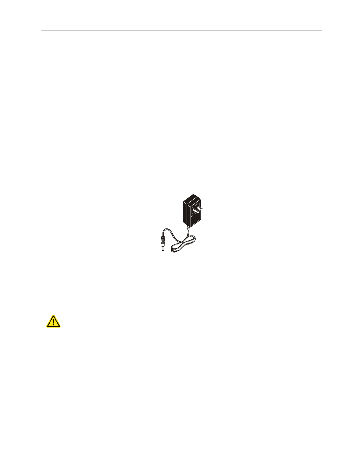
2.3.1. Operating the Display and Remote handset from AC Power
The Display (DH) and Remote (RH) handset can also be operated from an external DC source
(AC/DC adapter). The adapters are universally applicable.
Illustration 2.3.1. Adapter for LanTEK
®
II DH and RH
When using the AC/DC adapter to power the handsets, please note that:
Both handset batteries will receive a trickle charge.
A power plug will appear in the upper left corner of the Display handset (DH).
Page 20

Chapter 2
19
NOTE:
Charge time depends on charge state of battery.
Product Description
2.3.2. Battery Charging
The batteries of the Display (DH) and Remote (RH) handset are charged using the adapter. It
takes approximately 6-8 hours until the batteries in the instrument are fully charged. If the
batteries are charged externally, charge time is approximately 4 hours.
During recharging, the instrument is calibrated to the corresponding battery. This ensures an
accurate indication of the charge state at all times.
When the battery is removed, the Display handset (DH) data and preferences are preserved
in the flash ROM by a coin cell lithium battery.
2.4. Talkset
The LanTEK®II Cable Certifier is designed for use with a talkset. This function allows
communication between the Display (DH) and Remote (RH) handset through an externally
attached microphone/headset. For this purpose, the Display (DH) and Remote (RH) handset
must be connected to the test adapters through a cable.
Page 21
20
CHAPTER 3
Basics of the Cable Test
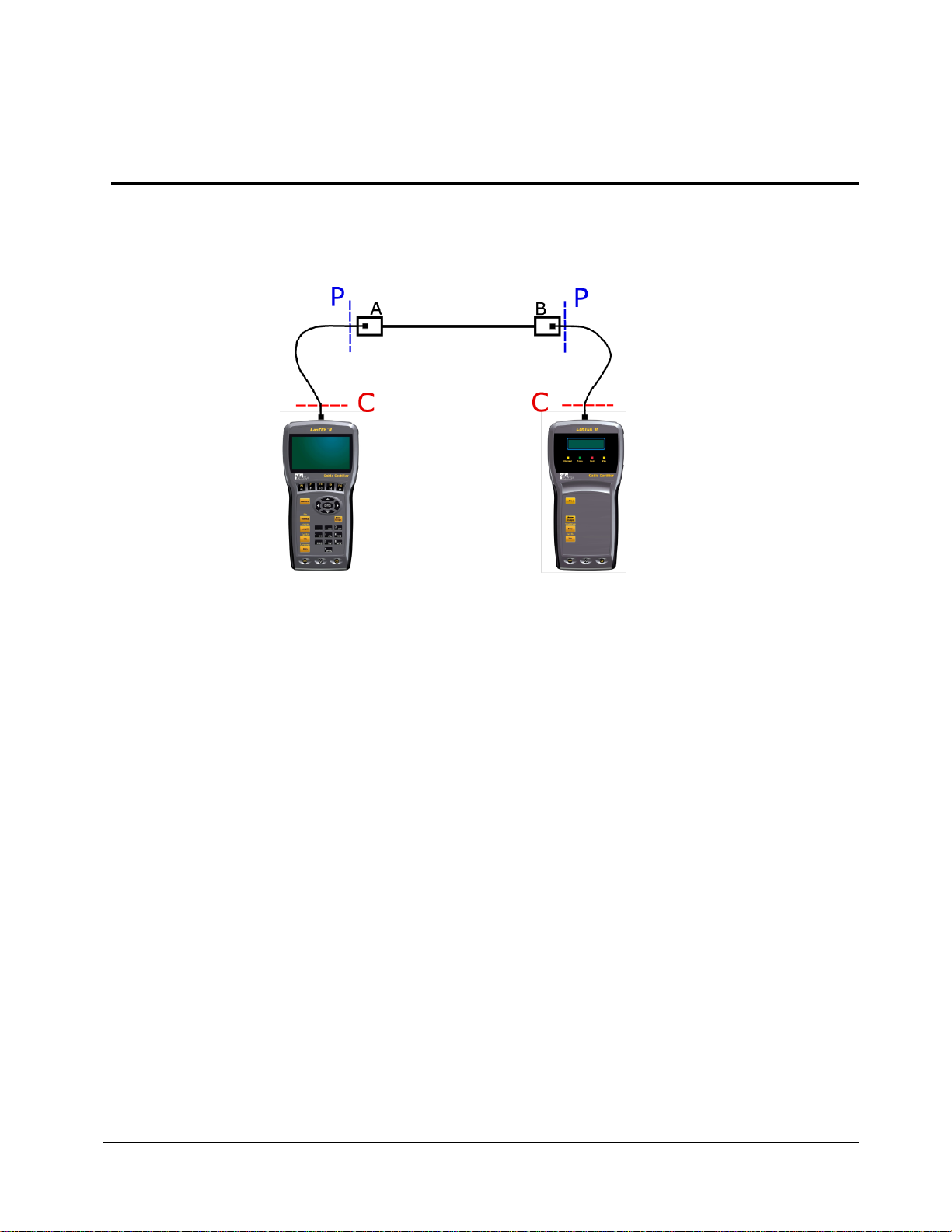
3.1. Testing of cables and relevant requirements
The following sections describe typical setup for permanent link and channel link testing.
Illustration 3.1. Illustration of test setup
The area marked with P indicates the typical test setup of a Permanent Link.
The area marked with C indicates the typical test setup of a Channel Link.
3.1.2. Setup for Permanent Link Test
The standards ANSI, EIA, TIA and ISO all differentiate between permanent link and channel
link on specifications for testing of communication networks. A permanent link consists of up
to 90 meters of horizontal cabling. (Maximum length limit applies to TIA standards only.) The
permanent link shown above serves to certify the installation of the horizontal cabling before
network connection and user hook-up. Adapters, patch cords and jumpers are excluded from
testing.
3.1.3. Setup for Channel Link Test
A channel link includes all components of a cabling system. It consists of up to 90 meters
horizontal cabling, including patch cords, jumpers, and test adapters at each cable end. The
channel link shown above serves to certify the network installation, including the horizontal
cable line and patch cord.
Page 22
21
CHAPTER 4
Preferences
Chinese
Korean
Czech
Norwegian
Dutch
Polish
English
Portuguese
French
Russian
German
Spanish
Italian
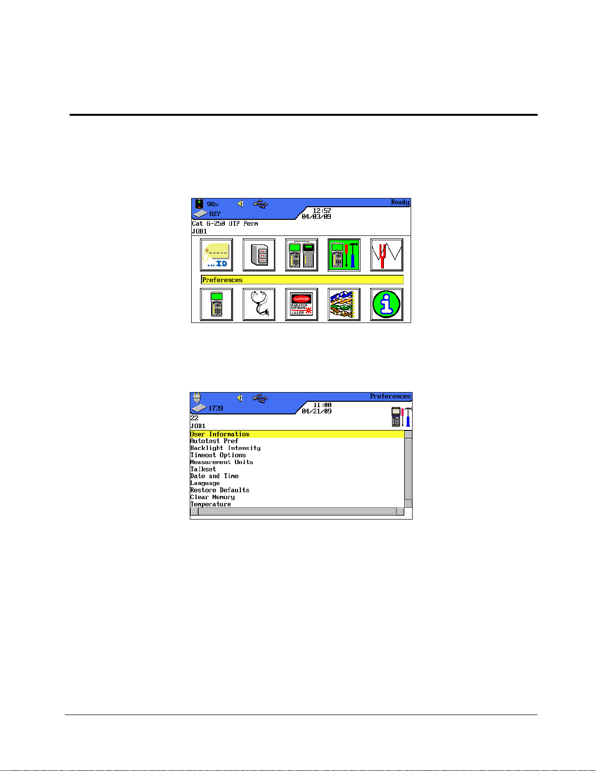
Most instrument configurations are set by using the "Preferences" menu.
4.1. Open Preferences
1. Use Arrow Keys to navigate to "Preferences" and press Enter.
Illustration 1 4.1. Open Preferences
Next, the instrument preferences can be set by using the listed menus.
Illustration 2 4.1. Preference Selection
4.2. Language
Menu navigation of LanTEK®II Cable Certifier is available in the following languages:
Page 23
22
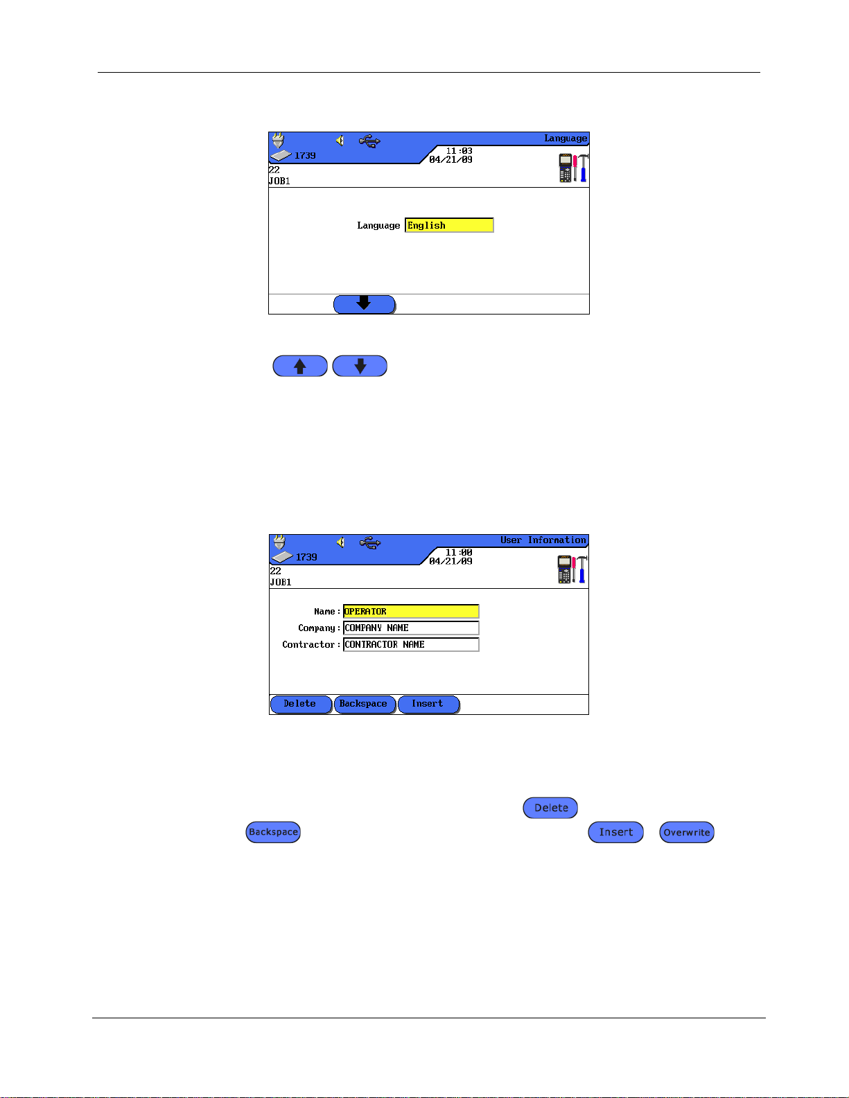
1. Use Arrow Keys to navigate to "Language" menu and press Enter. Alternatively,
open menu by using the Shift + Help / Language keys.
Illustration 4.2. Language
2. Use soft keys to select the desired language.
3. Press Enter to save the information entered. Escape allows you to exit the menu
without making changes.
4.3. User Information
Chapter 4
Preferences
This menu can be used to provide information on assigned Technician, Company and
Contractor.
1. Use Arrow Keys to navigate to "User Information" menu and press Enter.
Illustration 4.3. User Information
2. Use Arrow Keys to navigate to desired option Name, Company or Contractor.
3. Use Alphanumeric Keys to enter the desired information.
4. Make corrections to entries by using the soft keys (delete at cursor
position), (delete characters to the left of cursor), /
(insert alphanumeric characters at cursor position / overwrite highlighted entry).
5. Press Enter to save the information entered. Press Escape to exit the menu
without making changes.
4.4. Autotest Options
Use this menu to set Autotest options.
1. Use Arrow Keys to navigate to "Autotest Options" menu and press Enter.
Page 24
23
2. Use Arrow keys to select the desired option.
Backlight
1 minute
Tester
30 minutes
3. Use soft key to activate or deactivate the selected option. An activated
option is indicated by the green box.
4. Press Enter to save the information entered. Press Escape to exit the menu
without making changes.
4.5. Contrast
Chapter 4
Preferences
Illustration 4.4. Autotest Options
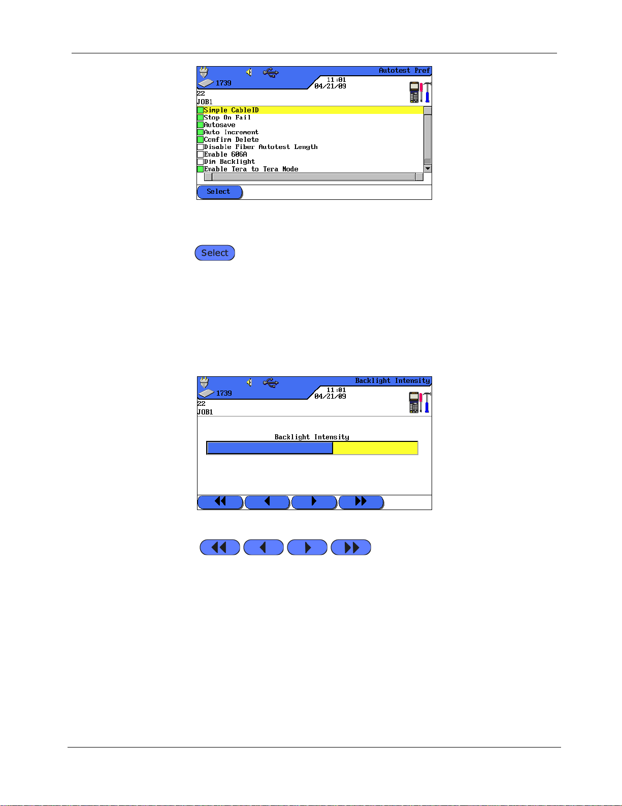
Use this menu to set Dim Backlight on screen.
1. Use Arrow Keys to navigate to "Contrast" menu and press Enter.
Illustration 4.5. Contrast
2. Use soft keys to set backlight intensity.
3. Press Enter to save the information entered. Press Escape to exit the menu
without making changes.
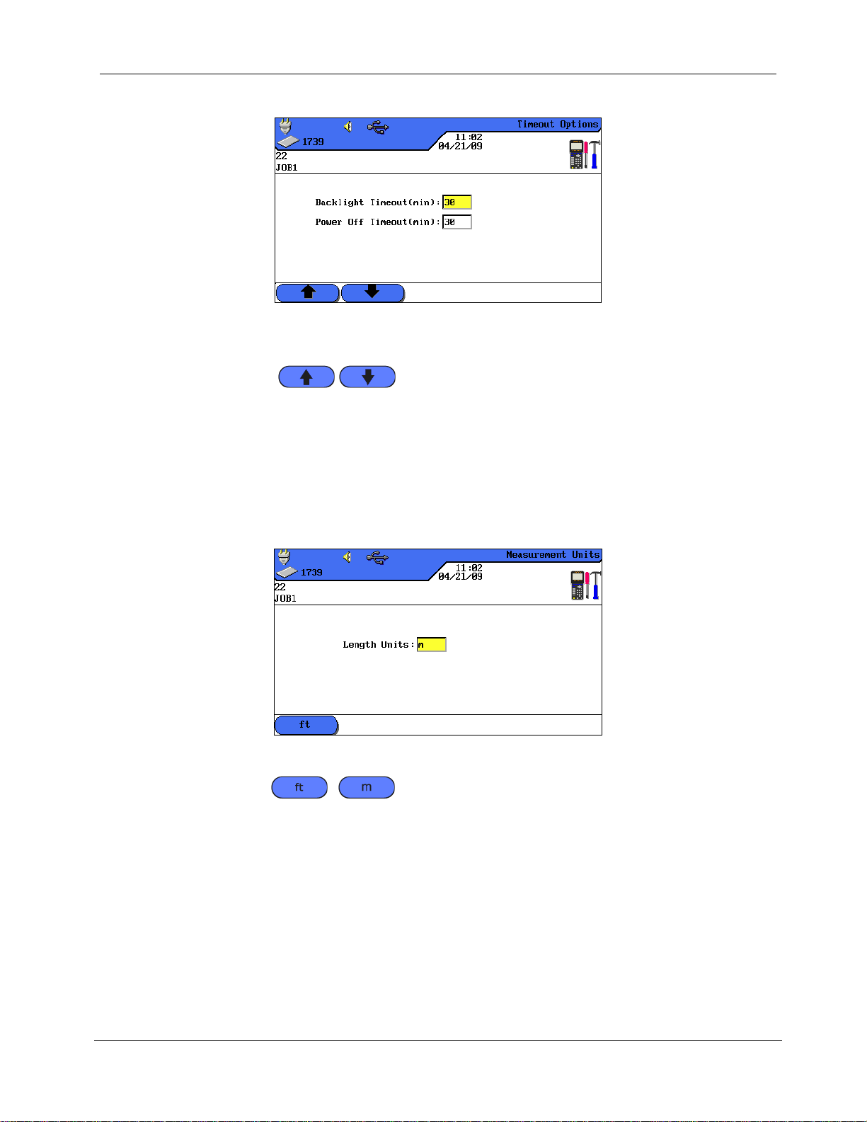
4.6. Timeout Options
Use this menu to set the time after which backlight automatically dims and the LanTEK®II
Cable Certifier automatically shuts down when tester is not in use.
Default settings:
Page 25
24
1. Use Arrow Keys to navigate to "Timeout Options" menu and press Enter.
Illustration 4.6. Timeout Options
2. Use Arrow keys to select the desired option.
3. Use soft keys to set the desired value.
4. Press Enter to save the information entered. Press Escape to exit the menu
without making changes.
4.7. Measurement Units
Chapter 4
Preferences
Use this menu to specify the measurement unit for length measurements ft or m (foot or
meter). The default setting depends on the language selected.
1. Use Arrow Keys to navigate to "Measurement Units" menu and press Enter.
Illustration 4.7. Measurement Units
2. Use soft key / (foot / meter) to select the desired unit.
3. Press Enter to save the information entered. Press Escape to exit the menu
without making changes.
Page 26
Chapter 4
25
Preferences
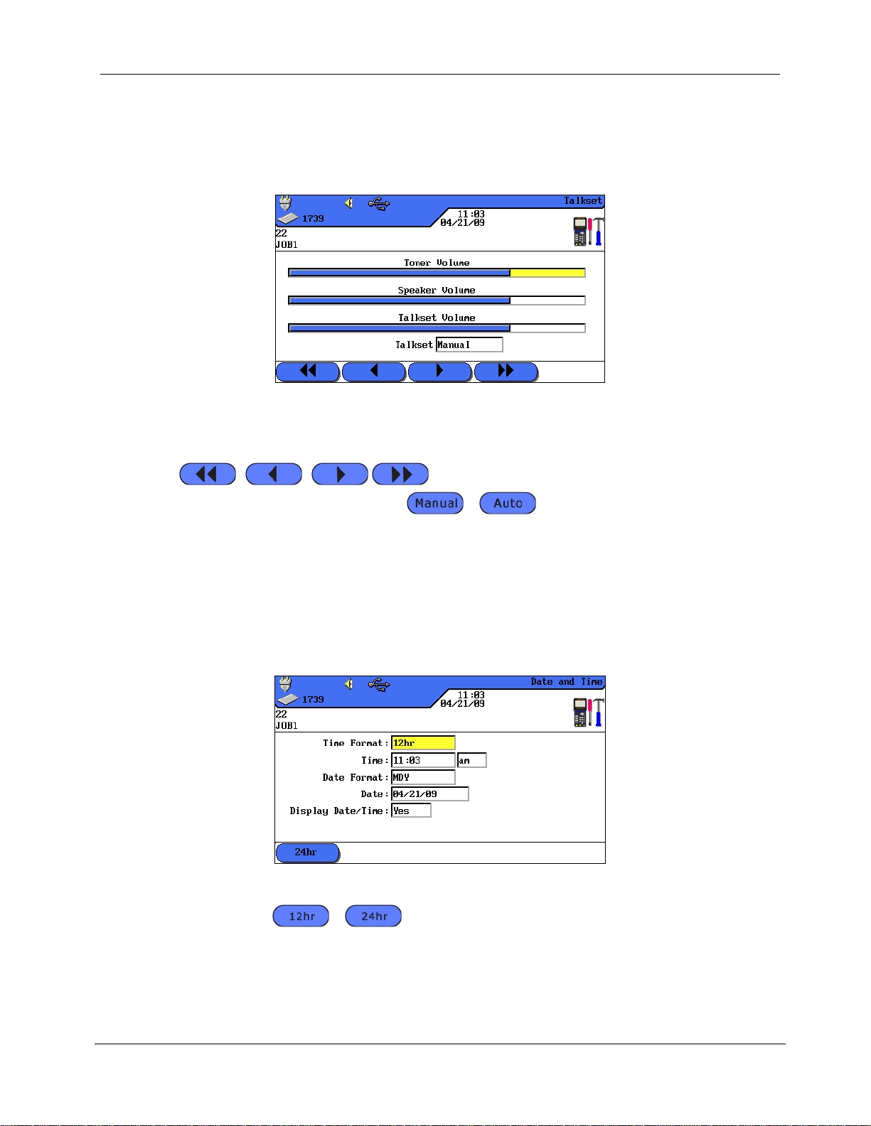
4.8. Talkset
Use this menu to set signal strength of tone generator, volume of internal speaker and
volume of talkset. Also use this menu to change the talkset mode.
1. Use Arrow Keys to navigate to "Talkset" menu and press Enter.
Illustration 4.8. Talkset
2. Use Arrow Keys to select the desired option.
3. On options Toner Volume, Speaker Volume or Talkset Volume, use soft keys
to set signal strength and volume.
4. On option Talkset, use soft key / to select desired setting.
5. Press Enter to save the information entered. Press Escape to exit the menu
without making changes.
4.9. Date and Time
Accurate date and time settings are important for the reliable identification of records and
test reports.
1. Use Arrow Keys to navigate to "Date and Time" menu and press Enter.
Illustration 4.9. Date and Time
2. Use soft key / to set the desired Time format.
3. Use Arrow Keys to navigate to option Time.
4. Use Alphanumeric Keys to enter the time.
5. Use Arrow Keys to navigate to option Date Format.
Page 27
26
6. Use soft keys to select the desired format MDY (month/day/year),
DMY (day/month/year) or YMD (year/month/day).
7. Use Arrow Keys to navigate to option Date.
8. Use Alphanumeric Keys to enter the date.
9. Use Arrow Keys to navigate to option Date/Time Display.
10. Use soft key / to select the desired setting.
11. Press Enter to save the information entered. Press Escape to exit the menu
without making changes.
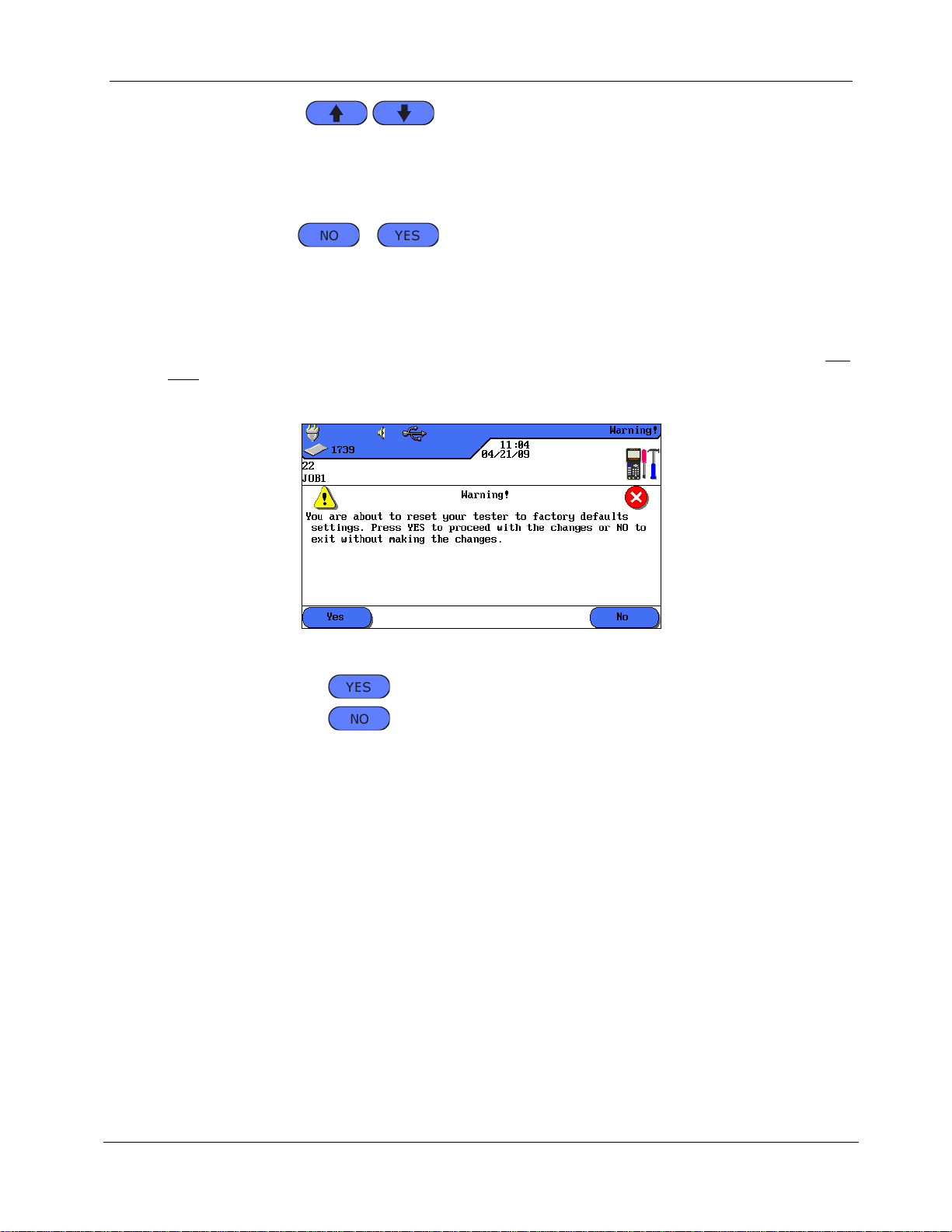
4.10. Restore Default
Use this menu to reset all tester settings to their factory defaults. Using this option will
not delete stored tests.
1. Use Arrow Keys to navigate to "Restore Defaults" menu and press Enter.
Chapter 4
Preferences
Illustration 4.10. Restore Defaults
2. Use the soft key to accept default settings.
3. Use the soft key to exit the screen without making changes.
Page 28
27
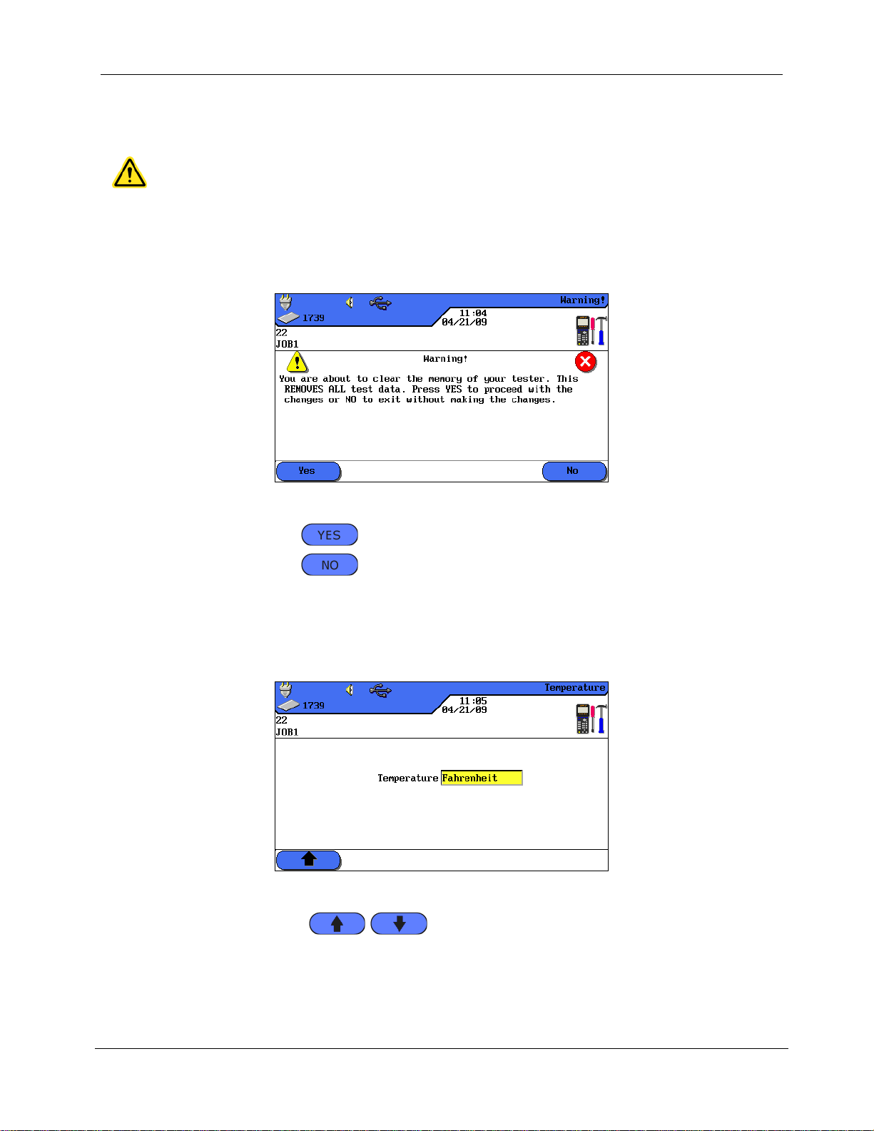
4.11. Clear Memory
CAUTION!
When using the "Clear Memory" menu, the records cannot be restored. This will
permanently delete all stored tests.
Use this menu to clear all records from the tester memory at one time.
1. Use Arrow Keys to navigate to Clear Memory menu and press Enter.
Chapter 4
Preferences
Illustration 4.11. Clear Memory
2. Use the soft key to clear the memory of the Cable Certifier.
3. Use the soft key to exit the screen without making changes.
4.12. Temperature
Use this menu to select the required temperature in Celsius or Fahrenheit.
1. Use Arrow Keys to navigate to "Temperature" menu and press Enter.
Illustration 4.12. Temperature
2. Use the soft keys to select the desired temperature.
3. Press Enter to save the information entered. Escape allows you to exit the menu
without making changes.
Page 29

28
CHAPTER 5
Autotest
NOTE:
If during the last 7 days no calibration has been performed on the identified Remote
handset (RH), the Autotest is cancelled and the user receives a message that a field
calibration is required.
Using Autotest, the installation can be measured and tested in a simple and fast way. After
pressing the AUTOTEST key, LanTEK®II Cable Tester automatically performs a number of
pre-programmed single tests. Autotest can be enabled from the Display (DH) or Remote (RH)
handset.
Selection of single tests from the test series depends on the type of cabling to be tested.
Specification of the test series is based on approved or recommended standards, as well as
specific parameters.
After the test series is completed, LanTEK®II Cable Tester displays an overall passed/failed
result, as well as the individual passed/failed results.
Preferences on Display handset (DH)
Set Autotest Pref.
Select job folder.
Set cable name (cable ID).
Select cable type.
Connections
Separate cable line to be tested from all network components.
Using suitable patch cords, connect the Display handset (DH) to one end of the cable line
(link), and the Remote handset (RH) to the opposite end of the cable line (link).
Test run
By pressing the AUTOTEST key, the test procedures described below are initiated:
First, the Display handset (DH) attempts to establish a connection to the Remote handset
(RH) via a correctly connected wire pair. If connection cannot be established, the Display
handset (DH) will show the message "Searching for Remote (RH). The search is continued
until the Autotest is manually cancelled or the Remote handset (RH) is located.
After connection to the Remote handset (RH) has been successfully established, its serial
number is read out to check if current configuration data are available.
Display handset (DH) continues the Autotest if serial number is valid. Most Autotests start
with the Wiremap test for twisted pair cables.
Following the Wiremap test, the other single tests that have been defined for the currently
selected cable type are performed.
After completion of Autotest, all test data can be displayed, saved and printed.
The test results of the last Autotest are stored in the non-volatile memory and remain
available for viewing even after the LanTEK®II Cable Tester is powered on or powered
down.
Page 30
Chapter 5
29
Symbol
Overall Autotest Result
The overall Autotest receives a passing grade if all single tests have been passed or
passed*.
The overall Autotest receives a failing grade if at least one single test has failed or
failed*.
Autotest Pref
Description
Simple cable ID
Assign name to cable line and set/reset meter reading of tests. The name
can be assigned as simple cable ID or double cable ID (Cable From/Cable
To).
NOTE:
If Simple Cable ID is not enabled, the cable name assigned will be
the default cable ID. In addition to cable name and test meter, an
initial value and a final value can be set, and the way of counting
can be specified.
Stop on Fail
The Autotest is stopped after the first failed test.
Autosave
The LanTEK®II Cable Tester automatically names and saves all results of
passed Autotests in the current job folder.
Auto Increment
The test meter for the cable ID is automatically advanced after each
Autotest.
Autotest
The test results of the last Autotest remain in the non-volatile memory until they are
overwritten by new test results, the memory is deleted or an analysis test is conducted.
Overall Passed/Failed Result
The overall result of Autotest is displayed after test series is completed.
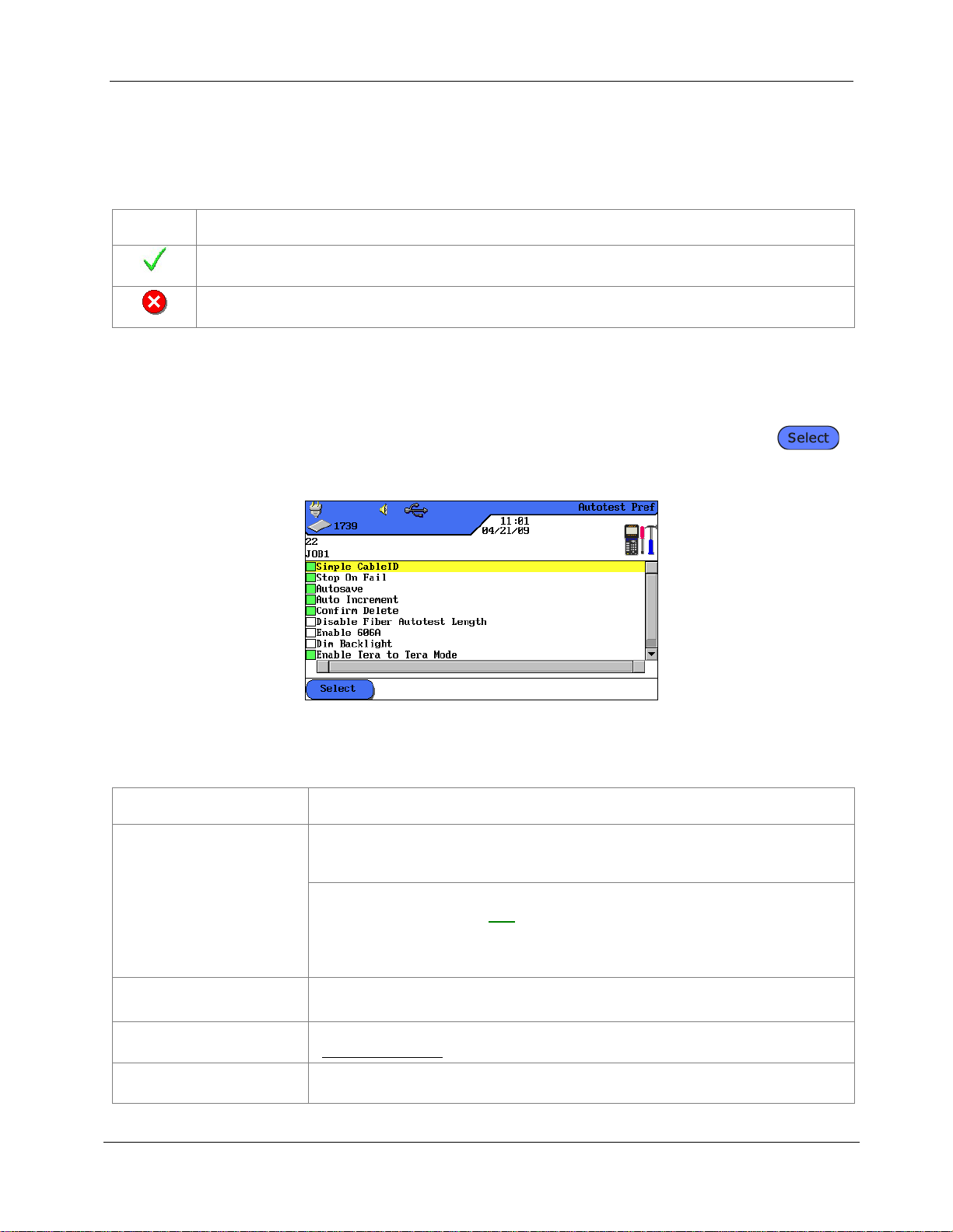
5.1. Set Autotest Pref
1. Open "Preferences" on start screen.
2. In "Preferences" open Autotest Pref.
3. Use Arrow Keys to navigate to the according Autotest Pref. Use soft key
to enable or disable the selected Autotest Pref. Enabled Autotest Pref are indicated
by green boxes.
Illustration 5.1. Autotest Pref
4. Press Enter to save the information entered. Escape allows you to exit the menu
without making changes.
Page 31

30
Autotest Pref
Description
This will permanently
delete the Tests / Jobs
from the tester
Enables confirmation prompt prior to deleting data.
Disable Fiber Autotest
Length
Enable / disable length measurement of fiber (LWL) with FiberTEK™ FDX
during Autotest.
Enable 606A
Enable labelling standard TIA/EIA 606-A for telecommunication
infrastructure as cable ID.
NOTE:
If labelling standard TIA/EIA 606-A is enabled; the selected cable
name (simple cable ID/default cable ID) is not applied.
Enable Tera to Tera
Mode
Enables Tera to Tera Mode instead of Tera to RJ45 Mode.
Enable Wiremap On
Failed Autotest.
In case of failed Autotest, it determines whether another fault analysis
will automatically be performed.
5.2. Select Job Folder
Chapter 5
Autotest
The name of the current job folder is shown in the TFT display on the ready screen. To save
the Autotest it is possible to keep this job folder, enable another existing job folder, or create
a new job folder.
5.2.1. Enable Existing Job Folder
1. Use Arrow keys to navigate to "File" and press Enter to open the job list.
Illustration 1 5.2.1. File
Page 32

Chapter 5
31
Autotest
Use Arrow Keys to navigate to the desired job folder. The display is highlighted yellow.
Illustration 2 5.2.1. Job List
2. Use soft key to open job options.
3. Use Arrow Keys to navigate to option Make Job Current. The display is
highlighted yellow.
Illustration 3 5.2.1. Job Options (example Current Job Info)
4. Press Enter to save the information entered. Escape allows you to exit the menu
without making changes.
5. When confirming with Enter, the name of the selected job folder will appear on
the ready screen.
5.2.2. Create New Job Folder
1. Use soft key to open job options in job list.
Illustration 1 5.2.2. Job List
Page 33

32
2. Use Arrow Keys to navigate to option New Job and press Enter.
Illustration 2 5.2.2. Job Options
3. Use Alphanumeric Keys to enter the desired information.
Chapter 5
Autotest
Illustration 3 5.2.2. New Job
4. Make corrections to entries by using the soft keys (delete at cursor
position), (delete characters to the left of cursor), /
(insert alphanumeric characters at cursor position / overwrite highlighted entry).
5. Press Enter to save the information entered. Escape allows you to exit the menu
without making changes.
6. When confirming with Enter, the name of the new job folder will appear on the
ready screen.
Page 34

Chapter 5
33
Autotest
5.3. Set Cable Name (cable ID)
The cable name of the cable lines in an Autotest consists of a fixed Cable Name and a
variable Current Value (4-digit test meter) that automatically increments. Depending on
selected Autotest Pref it is also possible to specify structure and way of counting.
1. Use Arrow keys to navigate to "Cable ID" and press Enter.
Illustration 5.3. Cable ID
The name used last will appear:
Single Cable ID (1 name is assigned to each cable).
or
Double Cable ID (2 names are assigned to each cable, one for the start and one for the
end of the cable).
Illustration 5.3. Cable ID
Increment… when pressing Enter, the current value of the test meter, shown in view
below, is incremented by one position.
Set… opens menu for cable name.
Select… switches between Single Cable ID and Double Cable ID.
Page 35

34
5.3.1. Simple Cable ID
2. Use Arrow keys to navigate in "Cable ID" view to option Set… and press Enter.
Single Cable ID (1 cable name)
3. Use Alphanumeric Keys to enter a Cable Name for the test portion.
4. Use Alphanumeric Keys to reset the Current Value of the test meter, or enter an
arbitrary value.
5. Make corrections to entries by using the soft keys (delete at cursor
position), (delete characters to the left of cursor), /
(insert alphanumeric characters at cursor position / overwrite highlighted entry).
Chapter 5
Autotest
Illustration 1 5.3.1. Single Cable ID
6. Press Enter to save the information entered. Escape allows you to exit the menu
without making changes.
Double Cable ID (2 cable names, start/end)
7. Use Alphanumeric Keys to enter a Cable Name for the Cable From/Cable To of
test portion.
8. Use Alphanumeric Keys to reset the Current Value of the test meter, or enter an
arbitrary value.
9. Make corrections to entries by using the soft keys (delete at cursor
position), (delete characters to the left of cursor), /
(insert alphanumeric characters at cursor position / overwrite highlighted entry).
Illustration 2 5.3.1. Double Cable ID
10. Use soft keys and to switch between the views Cable From and
Cable To.
Page 36

35
11. Use Alphanumeric Keys to enter a Cable Name for the Cable From/Cable To of
test portion.
12. Use Alphanumeric Keys to reset the Current Value of the test meter, or enter an
arbitrary value.
13. Make corrections to entries by using the soft keys (delete at cursor
position), (delete characters to the left of cursor), /
(insert alphanumeric characters at cursor position / overwrite highlighted entry).
14. Press Enter to save the information entered. Escape allows you to exit the menu
without making changes.
5.3.2. Default Cable ID
Simple cable ID was not selected in Autotest Pref.
1. Use Arrow keys to navigate in "Cable ID" view to option Set… and press Enter.
Simple Cable ID (1 cable name)
2. Use Alphanumeric Keys to enter a Cable Name for the test portion.
3. Use Alphanumeric Keys to reset the Current Value of the test meter, or enter an
arbitrary value.
4. Use Alphanumeric Keys to enter an arbitrary value for Start and End. Meter is
reset after reaching final value.
Chapter 5
Autotest
5. Make corrections to entries by using the soft keys (delete at cursor
position), (delete characters to the left of cursor), /
(insert alphanumeric characters at cursor position / overwrite highlighted entry).
6. Use symbol to lock a position into entered value. Use symbol to enable
Auto Increment of a character.
Illustration 1 5.3.2. Single Cable ID
7. Press Enter to save the information entered. Escape allows you to exit the menu
without making changes.
Double Cable ID (2 cable names, start/end)
1. Use Alphanumeric Keys to enter a Cable Name for the Cable From/Cable To of
test portion.
2. Use Alphanumeric Keys to reset the Current Value of the test meter, or enter an
arbitrary value.
Page 37

Chapter 5
36
Autotest
3. Use Alphanumeric Keys to enter an arbitrary value for Start and End. Meter is
reset after reaching final value.
4. Make corrections to entries by using the soft keys (delete at cursor
position), (delete characters to the left of cursor), /
(insert alphanumeric characters at cursor position / overwrite highlighted entry).
5. Use symbol to lock a position into entered value. Use symbol to enable
Auto Increment of a character.
Illustration 2 5.3.2. Double Cable ID
6. Use soft keys and to switch between the views Cable From and
Cable To.
7. Use Alphanumeric Keys to enter a Cable Name for the Cable From/Cable To of
test portion.
8. Use Alphanumeric Keys to reset the Current Value of the test meter, or enter an
arbitrary value.
9. Use Alphanumeric Keys to enter an arbitrary value for Start and End. Meter is
reset after reaching final value.
10. Make corrections to entries by using the soft keys (delete at cursor
position), (delete characters to the left of cursor), /
(insert alphanumeric characters at cursor position / overwrite highlighted entry).
11. Use symbol to lock a position into entered value. Use symbol to enable
Auto Increment of a character.
12. Press Enter to save the information entered. Escape allows you to exit the menu
without making changes.
Page 38

Chapter 5
37
Default
Example 1
Example 2
Example 3
"Cable From"
"Cable To"
Cable name:
TEST
Current: 0 0 0 0
Start: 0 0 0 0
End: 9 9 9 9
Cable name:
PANEL 1
Current: 0 0 0 0
Start: 0 0 0 0
End: 0 0 2 2
Cable name:
PANEL 2
Current: 0 1 8 A
Start: 0 0 0 A
End: 0 9 9 D
Cable name:
OFFICE 2
Current: 0 0 0 0
Start: 0 0 0 0
End: 9 9 9 9
Cable name:
Distributor
Current:0 0 0
A
Start: 0 0 0 A
End: 0 0 9 D
0 0 0 0
0 0 0 0
0 1 8 A
0 0 0 0
0 0 0 A
0 0 0 1
0 0 0 1
0 1 8 B
0 0 0 1
0 0 0 B
0 0 0 2
0 0 0 2
0 1 8 C
0 0 0 2
0 0 0 C
0 0 0 3
0 0 1 0
0 1 8 D
0 0 0 3
0 0 0 D
0 0 0 4
0 0 1 1
0 1 9 A
0 0 0 4
0 0 1 A
0 0 0 5
0 0 1 2
0 1 9 B
0 0 0 5
0 0 1 B
0 0 0 6
0 0 2 0
0 1 9 C
0 0 0 6
0 0 1 C
0 0 0 7
0 0 2 1
0 1 9 D
0 0 0 7
0 0 1 D
0 0 0 8
0 0 2 2
0 2 0 A
0 0 0 8
0 0 2 A
0 0 0 9
0 0 0 0
0 2 0 B
0 0 0 9
0 0 2 B
0 0 1 0
0 0 0 1
0 2 0 C
0 0 1 0
0 0 2 C
0 0 1 1
0 0 0 2
0 2 0 D
0 0 1 1
0 0 2 D
0 0 1 2
0 0 1 0
0 2 1 A
0 0 1 2
0 0 3 A
Autotest
Examples for Default Cable ID
In default setting, the meter starts at 0000 and ends at 9999. The four (4) positions are
enabled and incrementing.
5.4. Labeling Standard TIA/EIA 606-A
The standards TIA/EIA 606-A for telecommunication infrastructure include the following
elements:
Horizontal cable arrangements and cabling.
Backbone cable arrangements and cabling.
Grounding/potential equalization for telecommunication systems.
Rooms (e.g. service connection room, telecommunication room, equipment
Room and fire protection installations.
The mentioned standards affect the administration of telecommunication infrastructure by:
Assigning identifiers to infrastructure components.
Specifying information elements on which the infrastructure is based.
Specifying the relation between these records to ensure the contents.
Specifying reports that contain information on record groups and
Specifying the requirements on graphs and symbols.
Page 39

Chapter 5
38
AAA
A - AA
0000
Floor
Telecom room
Panel
Port
Autotest
5.4.1. Cable Name in Format TIA/EIA 606A
To determine cable name, a structure for the test portion is created. The three (3) cable
parameters 606A Drop, 606A Backbone and 606A Backbone Pair/Fiber are available.
1. Use Arrow keys to navigate to "Cable ID" and press Enter.
Illustration 5.4. Cable ID
5.4.2. Cable Parameter 606A Drop
Name of horizontal cable line (e.g. 1 building, 1 floor, 1 distribution, sockets)
2. Use soft key Drop to select cable parameter 606A Drop.
Illustration 1 5.4.2. Cable Parameter 606A Drop
3. Use Left/Right Arrow Keys to navigate to desired position in port area. Use
Up/Down Arrow Keys to assign characters and numbers.
4. Proceed in the same manner with positions Panel, Telecom Room and Floor.
5. Use soft key to hide individual positions. Assembling the cable line
automatically generates the 606A-Name.
6. Press Enter to save the cable name. Use Escape to exit menu without making
changes.
Page 40

Chapter 5
39
AAA
A / AAA
A - 00
Floor
Telecom room
Floor
Telecom room
Port
5.4.3. Cable Parameter 606A Backbone
Name of a horizontal and vertical cable line (e.g. several floors, several distributions,
sockets).
1. Use soft key Backbone to select cable parameter 606A Backbone.
Illustration 1 5.4.3. Cable Parameter 606A Backbone
Autotest
2. Use Left/Right Arrow Keys to navigate to desired position in port area. Use
Up/Down Arrow Keys to assign characters and numbers.
3. Proceed in the same manner with positions Telecom Room and Floor.
4. Use soft key to hide individual positions. Assembling the cable line
automatically generates the 606A-Name.
5. Press Enter to save the cable name. Use Escape to exit menu without making
changes.
5.4.4. Cable Parameter 606A Backbone Pair/Fiber
Name of a horizontal and vertical cable line with a pair/fiber connection (e.g. building, several
floors, several distributions, sockets).
1. Use soft key to select cable parameter 606A Backbone Pair/Fiber.
Illustration 1 5.4.4. Cable Parameter 606A Backbone Pair/Fiber
Page 41

40
AAA
A / AAA
A - 00 . 000
Floor
Telecom room
Floor
Telecom room
Port
Pair
2. Use Left/Right Arrow Keys to navigate to desired position in Pair area. Use
Up/Down Arrow Keys to assign characters and numbers.
3. Proceed in the same manner with positions Port, Telecom Room, and Floor.
4. Proceed in the same manner with positions Telecom Room and Floor.
5. Use soft key to hide individual positions. Assembling the cable line
automatically generates the 606A-Name.
6. Press Enter to save the information entered. Escape allows you to exit the menu
without making changes.
5.5. Select Twisted Pair Cabling
1. Open "Cable Type" on start screen.
2. Use Arrow Keys to navigate to installation type of cable line to be tested (Twisted
Pair Perm, Twisted Pair Basic or Twisted Pair Channel) and confirm with Enter.
Chapter 5
Autotest
Illustration 1 5.5. Cable Type
3. Use Arrow Keys to navigate to desired cable type.
Illustration 2 5.5. Example Twisted Pair Perm
4. Press Enter to save the information entered. Escape allows you to exit the menu
without making changes.
Or
Page 42

41
5. Use available soft key options to specify a cable type, create a cable type, edit NVP
values or enter reference temperature.
5.5.1. Specify Cable Type
1. Use soft key to open select menu to specify the selected cable type.
2. Use Arrow keys to navigate to desired specification and confirm with Enter.
Illustration 5.5.1. Specification of Cable Type
3. Press Enter to save the information entered. Escape allows you to exit the menu
without making changes.
Chapter 5
Autotest
5.5.2. Create Cable Type
1. Use soft key to open select menu for individual creation of a cable type.
2. Use Arrow keys in Select Menu to navigate to option Frequency Range and
confirm with Enter.
Illustration 1 5.5.2. Select Menu
3. Use Arrow Keys to navigate to the individual boxes and use Alphanumeric Keys
to assign start and stop frequencies for Certification and Performance Range.
Page 43

Chapter 5
42
Autotest
Illustration 2 5.5.2. Frequency range
4. Press Enter to save the information entered. Escape allows you to exit the menu
without making changes.
5. Use Arrow keys in Select Menu to navigate to option Connector Pinout and
confirm with Enter.
6. Use Arrow keys to navigate to desired pairings and enable or disable your
selection with soft key . An enabled pairing is indicated by the green box.
Illustration 3 5.5.2. Connector Pinout
7. Press Enter to save the information entered. Escape allows you to exit the menu
without making changes.
8. Use Arrow keys in Select Menu to navigate to option Test Limits and confirm with
Enter.
9. Use Arrow keys to navigate to the individual boxes and assign desired limit with
the Alphanumeric Keys.
Illustration 4 5.5.2. Test Limits
Page 44

Chapter 5
43
Autotest
10. Press Enter to save the information entered. Escape allows you to exit the menu
without making changes.
11. Use Arrow keys in Select Menu to navigate to option Link Models and confirm
with Enter.
12. Use soft key to select the link model Perm, Basic, Channel, EIA, Flat Rate,
Ignore or Skip.
Illustration 5 5.5.2. Link Models
13. Use Arrow Keys to navigate to the individual boxes and use Alphanumeric Keys
to assign the values for NEXT, Insertion Loss, Return Loss and ACR-F (ELFEXT).
14. Press Enter to save the information entered. Escape allows you to exit the menu
without making changes.
15. Use Arrow keys in Select Menu to navigate to option Select Autotest and confirm
with Enter.
16. Prepare the desired measuring modes for the Autotest by using Arrow Keys to
navigate to the desired measuring modes. Enable or disable your selection with
soft key . An enabled measuring mode is indicated by the green box.
Illustration 6 5.5.2. Select Autotests
17. Press Enter to save the information entered. Escape allows you to exit the menu
without making changes.
18. Use Arrow keys in Select Menu to navigate to option Custom Name/NVP and
confirm with Enter.
19. Use Alphanumeric Keys to assign a name for the created cable type.
Page 45

Chapter 5
44
Autotest
20. Make corrections to entries by using the soft keys (delete at cursor
position), (delete characters to the left of cursor), /
(insert alphanumeric characters at cursor position / overwrite highlighted entry).
Illustration 7 5.5.2. Custom Name/NVP
21. Use Arrow keys to navigate to the individual boxes and assign desired NVP with
the Alphanumeric Keys.
22. Press Enter to save the information entered. Escape allows you to exit the menu
without making changes.
5.5.3. Edit and Calculate NVP
1. Use soft key to open Select Menu for editing and calculating NVP.
2. Use Arrow keys to navigate to the individual boxes and assign desired NVP with
the Alphanumeric Keys.
Illustration 1 5.5.3. NVP
3. Use soft key to open menu for entering cable length.
4. Use Arrow Keys to navigate to box and use Alphanumeric Keys to assign Cable
Length (m).
5. Connect cable to be tested.
Page 46

45
Illustration 2 5.5.3. Cable Length
6. Use soft key to start calculation of NVP.
7. Press Enter to save NVP. Use Escape to exit menu without making changes.
5.5.4. Enter Reference Temperature
1. Use soft key to open Select Menu for changing ambient temperature.
2. Use Alphanumeric Keys to assign reference temperature.
Chapter 5
Autotest
Illustration 5.5.4. Reference Temperature
3. Press Enter to save the reference temperature. Use Escape to exit menu without
making changes.
Page 47

Chapter 5
46
Autotest
5.6. DualMODE™ Function for Twisted Pair Cabling
The DualMODE™ function of LanTEK®II Cable tester allows measurement in compliance with 2
limits in one single Autotest. Thus, for instance, simultaneous Channel Link and Permanent
Link measurements can be performed.
With DualMODE™ it is possible to perform other important tests. Let us assume you are
installing a Cat-6 system in a country whose government agency uses a national standard
based on ISO. But you are working with cables and connection components manufactured by
a company in the US. The government agency can request a certification according to ISO
Class E from the installer. However, for warranty reasons the US company might insist on TIA
568 Category 6. Therefore, in the past both certifications were required - in compliance with
ISO and TIA - and the increased costs had to be passed on to the customer. In contrast,
DualMODE™ makes it possible to perform both certifications at the same time, in compliance
with ISO Class E Permanent Link and TIA 568B Category 6. The costs are the same as for one
test.
Another example for the use of DualMODE™ is the calculation of margins in relation to higher
bandwidth for future applications. Up to now you had to check the certification documents for
Category 6 Permanent Link and assess whether adequate margins for transmission of
applications at higher bandwidth are available. However, assessment of the complete final
data would also require a certification according to Category 6A. Due to higher test costs,
these measures would usually not be performed.
With DualMODE™ you can certify the system in compliance with Category 6, and perform
tests with the limits of Category 6A. Due to unmistakable data, your customer would know
exactly what cable lines support higher bandwidths in future applications. This information
would be of great importance when making a decision on whether to assemble cables with
connectors of a higher category, or to pull in cables of a higher category.
5.6.1. Implement DualMODE™
1. Open "Cable Type" on start screen.
2. Use Arrow Keys to navigate to function Twisted Pair DualMODE™ and confirm
with Enter.
Illustration 1 5.6.1. Twisted Pair DualMODE™
3. Use Arrow Keys to navigate to desired cable types. Use soft key to
enable, and soft key Deselect All to disable your selection. An enabled pairing is
indicated by the green box.
4. If you would like another link model, or edit and calculate NVP for the DualMODE™
pairing, press Shift.
Page 48

Chapter 5
47
Autotest
5. Press AUTOTEST. The passed/failed results are displayed. For each DualMODE™
test, the worst case margins and values for NEXT, RL, ACR und Loss are indicated.
Illustration 2 5.6.1. Overall DualMODE™ Result
6. Use Enter to load the corresponding graphical result displays of the highlighted
test.
5.7. Edit NVP Default Value of a Cable
To perform length measurement, the nominal velocity of propagation (NVP) of the cable must
be known. This value can be found in the technical cable information. If this information is
not available, a cable of known length (ca. 30 – 60 meter) should be connected, and the NVP
calculated by LanTEK®II Cable Tester.
1. Open "Cable Type" on start screen.
2. Use Arrow Keys to navigate to desired cable type.
Illustration 1 5.7. NVP Default Value
3. Use soft key to open menu for entering NVP.
Page 49

48
Illustration 2 5.7. Enter NVP
NOTE:
This concerns a channel measurement. When entering the cable length, the length of both
patch cords must be considered.
CATV standards
Ethernet standards
Other cable types
RG59 31 or 92 m
(3-fold or 4-fold shield)
10Base 2
IBM Coax
RG6 31 or 92 m
(3-fold or 4-fold shield)
10Base 5
TWINAXIAL
ARCNET
4. Use Alphanumeric keys to enter one or several NVP.
5. For automatic calculation of a new NVP, press .
Chapter 5
Autotest
Illustration 3 5.7. Calculation of NVP
6. Connect a cable of known length.
7. Use Arrow Keys and Number Keys to enter known cable length.
8. For automatic calculation of a new NVP, press . After calculation of new
NVP, the display returns to the NVP main screen.
5.8. Coaxial Cable Standards
The LanTEK
®
II Cable Tester supports the following coaxial cable standards:
1. Open "Cable Type" on start screen.
Page 50

Chapter 5
49
Cable Types
Resistance
Length
Loss
Return loss
Impedance
RG59 31 or 92 m
X
X
X X X
RG6 31 or 92 m
X
X X X
X
IBM Coax
X X X
TWINAX, ARCNET
X X X
10BASE2
(IEEE 802.3)
X X X
10BASE5
(IEEE 802.3)
X X X
Autotest
2. Use Arrow Keys to navigate to option Ethernet and confirm with Enter.
Illustration 1 5.8. Ethernet
3. Use Arrow Keys to navigate to desired cable type and confirm with Enter.
Illustration 2 5.8. Cable Type
5.8.1. Autotest Test Series for Coaxial Cables
Page 51

Chapter 5
50
NOTE:
It is imperative not to mix up the corresponding patch cords for Display handset (DH) and
Remote handset (RH), and they must also be used for the cable test. We recommend to
mark the patch cords accordingly.
Autotest
5.9. Calibration
A field calibration must be performed if:
During the last 7 days no calibration has been performed. The user receives a message,
informing him that a field calibration is required.
The test adapter has been changed.
A patch cord has been changed.
5.9.1. Twisted Pair Cabling
1. Use Arrow Keys to navigate to "Calibration" and press Enter to open job list.
Illustration 1 5.9.1. Ready screen
Calibration requires one patch cord each for the Display handset (DH) and the Remote
handset (RH).
2. Connect Display handset (DH) and Remote handset (RH) with patch cord for
Remote handset (RH), as shown on the display. Remember which connection of
the patch cord is connected to the Remote handset (RH).
Illustration 2 5.9.1. Patch Cord (RH)
3. Use soft key to initiate calibration. The Remote handset (RH) indicates
calibration, and a progress bar shows the status.
Page 52

Chapter 5
51
Autotest
4. Connect Display handset (DH) and Remote handset (RH) with patch cord for
Display handset (DH), as shown on the display. Remember which connection of the
patch cord is connected to the Display handset (DH).
Illustration 3 5.9.1. Patch Cord (DH)
5. Use soft key to continue calibration. The Remote handset (RH) indicates
calibration, and a progress bar shows the status.
6. Perform the same patch cord connections to Display handset (DH) and Remote
handset (RH) as during the previous test steps.
Illustration 5.9. Open Patch Cord
7. On Display handset (DH) use soft key to start the last step of calibration.
8. On Remote handset (RH) use Autotest to start the last step of calibration.
Illustration 4 5.9.1. Calibration Complete
9. On Display handset (DH) press Escape to return to screen. The Remote handset
(RH) briefly displays that calibration was successful, and then shows ready state.
Page 53

Chapter 5
52
NOTE:
The LanTEK®II Cable Tester COAX adapters are equipped with BNC connections. COAX
cables applied by the user must convert from/to BNC and F (CATV) or other plug types.
Autotest
5.9.2. Coaxial Cable
Calibration must be performed if:
During the last 7 days no calibration has been performed. The user receives a message,
informing him that a field calibration is required.
The test adapter has been changed.
A patch cord has been changed.
For calibration with COAX adapters, the LanTEK®II process, consisting of 4 steps, is changed.
Since the coaxial cables are tested at low frequencies, the additional data received during
calibration are largely ignored, thus calibration with LanTEK®II Cable Tester is already
completed after one step.
1. Open "Cable Type" on start screen.
2. Use Arrow Keys to navigate to option Ethernet and confirm with Enter.
3. Use Arrow Keys to navigate to desired cable type and confirm with Enter.
4. Connect Coax adapters to Display handset (DH) and Remote handset (RH).
5. Connect the short coaxial calibration cable to the adapters of Display handset (DH)
and Remote handset (RH).
6. Use Arrow Keys to navigate on ready screen to "Calibration" and press Enter.
Illustration 1 5.9.2. Ready Screen
7. Use soft key to initiate calibration.
Illustration 2 5.9.2. Coaxial Cable Calibration
Page 54

Chapter 5
53
Job Options
Description
Current Job Info
The display shows the total number of passed/failed tests, cable
length and memory used for the highlighted job folder.
All Job Info
The display shows the total number of passed/failed tests, cable
length and memory used for all highlighted job folders.
Permanently Delete Selected
Jobs
The selected job folder is deleted.
Rename Job
Renaming highlighted job folder.
New Job
Adding a new job folder to job list.
Make Job Current
Enables highlighted job folder. Autotests are now stored under this
job.
Autotest
8. After completion of calibration and display of according message, press Escape to
return to main screen.
5.10. Perform Autotest
Autotest is performed after all preferences have been carried out.
1. Disconnect the cable line to be tested from all network components.
2. Using suitable patch cords, connect the Display handset (DH) to one end of the
cable line (link), and the Remote handset (RH) to the opposite end of the cable line
(link).
3. Start by pressing Autotest.
5.11. Open Job Folder of Autotest
The internal memory of LanTEK®II Cable Tester can hold a maximum of 1700 individual TIA
CAT-6 Autotest results with graphs, which can later be loaded again via File . The Autotest
results can be saved immediately after the test.
The complete set of test results is saved in a file.
The test results are automatically saved if Autosave option is enabled.
Completed tests are automatically assigned a name. If another name is desired, the test
can be renamed via option Rename.
5.11.1. Job Options
1. Open "File" on start screen.
2. Use Arrow Keys to navigate to the desired job folder. The display is highlighted
yellow.
3. Use soft key to open job options.
5.11.2. Test Options
1. Use Arrow Keys to navigate to the desired job folder. The display is highlighted
yellow.
2. Press Enter to display single tests.
Page 55

Chapter 5
54
Test Options
Description
Select all
Selects all stored test results.
Select All Passed
Selects only passed tests for editing.
Select All Failed
Selects only failed tests for editing.
Deselect All
Deselects all stored test results.
Permanently Delete Selected
Tests
Deletes highlighted test results.
Permanently Delete All
Deletes all stored test results.
Test Options
Description
Results Info
Displays information on test results, such as number of tests,
number of passed/failed tests. Tested lengths and memory used.
Selected Results Info
Displays results of selected tests.
Rename Test
Renames selected test results.
Autotest
3. Use soft key to open Test Options.
5.11.3. Copy Job Folder to USB Removable Storage
1. Insert the USB removable storage into the USB port of Display handset (DH).
2. Navigate in job list with Arrow Keys to job folder to be copied, and highlight it
with soft key (it is possible to highlight several job folders).
3. Use soft key to open job options.
4. Navigate with Arrow Keys to Copy Selected Jobs to USB Flash Drive and press
Enter.
5.11.4. Alien Crosstalk Measurements (AXT)
Use soft key in display of job list to open the saved Alien Crosstalk Measurements
and to copy them to a USB removable storage.
5.12. Autotest Results and Graphs
The Autotest results can be displayed as table or graph.
1. Open "File" on start screen.
2. Use Arrow Keys to navigate to the desired job folder. The display is highlighted
yellow.
3. Use Arrow Keys to navigate to desired single test. The display is highlighted
yellow.
4. Press Enter to display overview of single tests.
Page 56

55
Illustration 1 5.12. Single test overview
5. Press Enter again to open test series of single test.
Chapter 5
Autotest
Illustration 2 5.12. Test series
6. Use Arrow Keys to navigate to desired test series and press Enter to display
result table.
Illustration 3 5.12. Result Table
7. Use Arrow Keys to navigate to desired test result and press Enter to display
graph.
Page 57

Chapter 5
56
Table view
Graph view
Description
1
Wire pair, plotted on the basis of the table data.
2
Specified limit curve for worst case loss value.
Illustration 4 5.12. NEXT Graph
When opening graph, cursor is always in worst case margin. In this example, cursor is
positioned on horizontal axis at 186 MHz.
8. Press Escape to return to previous screen.
Autotest
5.12.1. Graph Formats, Layouts and Controls
Graphs make it easier to recognize the relation between two network parameters, the
actually measured values and the pre-programmed limits.
The horizontal axis indicates the frequency values and the vertical axis the measured values
in dB. The limits are drawn as solid line.
Illustration 5.12.1. Table View and Graph View
The margins indicated at lower right in table view provide information on worst case distance
between the actual measuring values and the specified limits, as shown by the cursor position
in the graph on the right.
Page 58

Chapter 5
57
3
The actual measurement curve of the wire pair. In this case, the loss is displayed.
4
The actual measurement curve of the wire pair.
5
Vertical axis with measuring values in dB.
6
Use arrow keys to move cursor horizontally. When cursor position is changed, the measuring
values displayed on screen are changed as well.
Use soft keys and to move cursor in larger steps.
Use Arrow Keys to move cursor in smaller steps.
While SHIFT key is pressed, cursor can be moved in large steps with Arrow Keys.
7
Enlargement or reduction of view of horizontal axis. At maximum size, these keys have no
function.
8
Horizontal axis with frequency values.
9
Specified limit curve for worst case NEXT value.
10
During initial display of wire pair graph, the cursor is automatically at worst case limit and
frequency location.
Autotest
Page 59

58
CHAPTER 6
Structured Cabling Testing
NOTE:
When pressing Escape, the Display handset (DH) stops Searching for Remote (RH) and
initiates the test under conditions that do not require a Remote handset (RH).
6.1. Test Setup for Single Test Analysis
Perform calibration if LanTEK
days.
Select cable type.
Separate cable line to be tested from all network components.
Connect adapter and patch cord to Display handset (DH) and Remote handset (RH).
Connect patch cord of display handset (DH) to one end of the cable line and the patch
cord of remote handset (RH) to the other end.
®
II Cable Tester has not been calibrated during the last 7
6.2. Test Run of Single Test Analysis
When performing an analysis test, the following sequences are initiated:
If test requires Remote handset (RH), the Display handset (DH) initially attempts to
establish a connection to the Remote handset (RH). If connection cannot be established,
the Display handset (DH) will show the message "Searching for Remote (RH). The search
is continued until the analysis test is manually cancelled or the Remote handset (RH) is
located.
After connection to the Remote handset (RH) has been successfully established, its serial
number is read out to check if current configuration data are available. If during the last 7
days no calibration has been performed on the identified Remote handset (RH), the user
receives a message that calibration is recommended.
Display handset (DH) continues the selected single test if serial number is valid.
If test does not require a Remote handset (RH), the Display handset (DH) performs the
test and displays the result.
Once test is completed, the results can be displayed or printed.
6.3. Perform Single Test Analysis
1. Connect Display (DH) and Remote (RH) handset to cable line that is to be tested.
2. Open "Analyze" on start screen.
3. The tests available for the selected cable type are displayed.
4. Use Arrow Keys to navigate to desired test.
Page 60

Chapter 6
59
Overall Result
Individual Results
Structured cabling testing
Illustration 6.3. Single Tests
5. Confirm selection of test with Enter. After completion of test, a result table opens.
6.4. Evaluation of Analysis Test Results
The overall result of the analysis test is displayed in the upper right on the screen below the
title bar. The results for the individual wire pairs are displayed on the right side of the
respective test.
The above example shows the screen for DC resistance.
The overall result of the test appears in the upper right, beside the date.
The results of the individual wire pairs appear in the last column on the right (result
column).
The results for the overall test and the single tests are indicated similar to Autotest.
6.4.1. Graphs for Analysis Tests
After completion of test series, certain analysis results can be displayed in table or graph
format. The graph display in analysis mode is comparable to the one of Autotest.
6.5. Overview of Single Test Analysis
Analysis mode allows fault repair by performing single tests, making changes and displaying
changed test results. With the analysis test it is possible to check the cable continuously for
damage or overstretching.
Illustration 6.4. Evaluation of Analysis Test Results
Page 61

Chapter 6
60
Wiremap
Resistance
Length
Capacitance
NEXT
Loss/Insertion Loss
ACR-N (ACR)
Return loss
Impedance
Delay and Skew
Power Sum NEXT
Power Sum ACR-N (Power Sum ACR)
Margin
ACR-F (ELFEXT)
Power Sum ACR-F (Power Sum ELFEXT)
NOTE:
The following tests do not require a Remote handset (RH): Resistance, Length,
Capacitance, Impedance, Delay and Skew.
Structured cabling testing
Depending on cable type and specified test standard, the following single test analyses are
available:
6.6. Wiremap Test
With the aid of Wiremap tests it is possible to pinpoint short circuits, interrupts and incorrect
wiring. To facilitate evaluation, the test results are displayed in graph format.
Illustration 6.6. Wiremap Test
An error indicated by the Wiremap test should always be corrected first, since it will cause
errors in other tests. An unwired contact can cause the tests for DC loop resistance and loss
to receive a failing grade as well. An interrupt can also lead to a zero result when testing
capacitance, resulting in failed NEXT measuring values.
The Wiremap test ensures the following minimum thresholds for fault recognition (based on
four wire pairs, optional shield):
All Wiremap errors or combined Wiremap errors are indicated as errors in the Wiremap
diagram.
All combinations of up to three interrupts, short circuits or reversed connections are
correctly detected.
In case of interrupts and short circuits, the cable end at which the error occurred is
indicated (on Autotest screen for length measurement).
Split wire pairs (Split Pairs) are detected by specific patterns of contradictory NEXT values
(Near End Cross-Talk).
Page 62

Chapter 6
61
Structured cabling testing
6.7. Length Test
This test determines the length of wire pairs to ensure that the recommended limits for the
selected cable are complied with. Depending on the measurement unit selected in
"Preferences", the length is indicated in Foot or Meter.
Illustration 6.7. Length Test
6.7.1. Length Test Error
Minor length differences can occur between the wire pairs of a cable due to small NVP
differences, as well as length differences caused by transposition. A failure exists if the
electronically measured cable length deviates too much from the actual length.
6.8. Resistance Test
This test determines the loop resistance of the individual wire pairs. This ensures that the
total loop resistance does not exceed the recommended limits. For each wire pair, the results
are displayed as resistance value in ohm, together with the reference limit for the cable type.
Illustration 6.8. Resistance Test
6.8.1. Resistance Test Error
All four wire pairs of a transmission line within the network should have approximately the
same resistance. If the resistance value of a wire pair exceeds the limit, the test is considered
failed.
6.9. NEXT, ACR-F (ELFEXT) and Power Sum
In an Autotest, crosstalk at the near and far end of the cable is measured with NEXT (Near
End Cross Talk) and ACR-F (ELFEXT) tests. High crosstalk levels can result in frequent
recurrences, damage to data and other interferences that impair transmission rate.
Page 63

Chapter 6
62
1
2
3
6
4
5
7
8
2
1
3
6
4
5
7
8
Effect of
Adjacent Pair
Structured cabling testing
Illustration 6.9. NEXT, ACR-F (ELFEXT) and Power Sum
The NEXT test determines interfering effects (crosstalk) of a transmitting wire pair on the
adjacent wire pair in the same cable. NEXT is measured on Display handset (DH) and Remote
handset (RH).
FEXT test and NEXT measurement are similar; the only difference is that in FEXT test the
transmissions emanate from Remote handset (RH) and that crosstalk is determined at
Display handset (DH).
NEXT measurements are performed on each cable end and for all wire pair combinations
(pair 1-2 to 3-6 etc.). Thus, a total of 12 measurements is performed.
ACR-F (ELFEXT) measurements take place with the Display handset (DH) and the Remote
handset (RH) on both cable ends and for all possible wire pair combinations (1-2 to 3-6,
3-6 to 1-2, 1-2 etc.). This results in a total of 12 measurements.
6.10. Power Sum NEXT, Power Sum ACR-F (ELFEXT)
Power Sum-Tests determine the crosstalk effects of three transmitting wire pairs on the
fourth wire pair in the same cable.
Page 64

Chapter 6
63
1
2
3
6
4
5
7
8
2
1
3
6
4
5
7
8
Effects of
3 Pairs on 1 Pair
NOTE:
The Power Sum NEXT values are usually 2 - 3 dB below the value (= stronger crosstalk)
than with conventional NEXT measurement.
Structured cabling testing
When using Power Sum NEXT, four (4) calculations on each cable end and on each wire pair
combination (pairs 1-2, 3-6 and 4-5 to 7-8 etc.) are performed. A total of eight (8) values is
obtained.
Illustration 1 6.10.1. Power Sum NEXT
When using Power Sum ACR-F (Power Sum ELFEXT), four (4) calculations on the side of the
Display handset (DH) and on each wire pair combination (pairs 1-2, 3-6 and 4-5 to 7-8 etc.)
are performed. A total of eight (8) values is obtained.
Illustration 2 6.10.1. Power Sum ACR-F (Power Sum ELFEXT)
6.10.1. NEXT Test and ACR-F (Power Sum ELFEXT) Test Error
Crosstalk is usually caused by faulty connections at the cable ends. The lower the measuring
values in dB, the stronger the crosstalk.
Page 65

Chapter 6
64
Structured cabling testing
6.11. Insertion Loss Test (Attenuation)
This test determines the overall insertion loss of the signal in the cable and checks
compliance with limits. A minor loss is the prerequisite for a faultless transmission. Insertion
loss measurement is performed by feeding a signal with known amplitude into the Remote
handset (RH) and then reading the amplitude on the Display handset (DH).
Illustration 6.11. Loss Test
6.11.1. Insertion Loss test Error
The insertion loss reduces the signal in the cable. Loss increases with cable length, signal
frequency and temperature. With the aid of loss tests it is possible to detect faults in cable,
connections and connection technology. A high loss value in dB indicates a strong loss, and
thus a higher signal reduction.
6.12. Return Loss Test
This test determines the relation between reflected and transmitted signal amplitude. Highgrade cable lines exhibit only minor reflection, thus demonstrating a good impedance
adjustment of the individual components connected to the cable.
Illustration 6.12. Return Loss Test
6.12.1. Return Loss Test Error
Same as with loss, an excessive return loss also results in signal reduction at the reception
end. It also indicates that an impedance mismatch exists in a section of the cable. A value of
20 dB or higher indicates a good twisted-pair cable.
Page 66

Chapter 6
65
NOTE:
The measurements are incorrectly calculated if the setting is for a type CAT 3 cable (the
cable insulation containing PVC), but the test is actually performed on a CAT 5 cable
(insulation containing Teflon ). Therefore, ensure that the correct cable type is selected.
Structured cabling testing
6.13. Impedance Test
The average impedance is calculated from delay of electrical signal and capacitance
measurement. The result is indicated in ohm. The average impedance can help in indentifying
damages to cable, connections or cable sections with impedance mismatch.
Since this test uses a capacity measurement, the correct cable type must be indicated to
obtain a precise measuring result.
Illustration 6.13. Impedance Test
6.13.1. Impedance Error
Impedance errors cause signal reflections and signal reduction. Average impedance of wire
pairs should comply with LAN system impedance of 100, 120 or 150 .
6.14. Delay and Skew Test
This test determines the delay of a test signal that was fed at one end of the cable to the
other end of the cable. The delay skew indicates the difference between the measured delay
of the corresponding wire pair and the wire pair with the lowest delay value. The limits
specified for delay and skew depend on selected cable type.
Illustration 6.14. Delay and Skew Test
Page 67

Chapter 6
66
Structured cabling testing
6.14.1. Delay and Skew Test Error
The delay and skew measurements usually result in slightly different values for the individual
wire pairs of a cable. However, a large difference indicates a cable fault or a damaged wire
pair.
6.15. Capacitance Test
This test determines the mutual capacitance between the two conductors of each wire pair, to
ensure that the capacitance of the corresponding cable type has not been impaired by the
installation.
The capacitance test of the analysis mode indicates the overall capacitance in Nanofarad
(nF).
The Autotest measures the overall capacitance in Picofarad (pF) per meter or foot.
Illustration 6.15. Capacitance Test
6.15.1. Capacitance Test Error
The higher the capacitance, the higher the error rate. Due to transport and installation of the
cable, minor changes in capacitance are normal. Connectors and patch cords also influence
capacitance values.
6.16. ACR-N (ACR) Test and Power Sum ACR-N (Power Sum ACR) Test
The ACR-N (ACR) test determines the loss-crosstalk distance by means of a mathematical
comparison (difference calculation) of the loss and NEXT test results. The differences between
the measuring values of a wire pair indicate whether transmission interferences are likely to
occur in the respective wire pair.
The ACR-N (ACR) measurement is calculated from pair to pair. Power Sum ACR-N (Power
Sum ACR) measurement is calculated by summation of NEXT values between a selected wire
pair and three other wire pairs of the same cable.
Page 68

Chapter 6
67
Structured cabling testing
Illustration 6.16. ACR-N (ACR) / Power Sum ACR-N (Power Sum
ACR)
6.16.1. ACR-N (ACR) Test and Power Sum ACR-N (Power Sum ACR) Test Error
A large difference between the measuring values is preferable, since this indicates a strong
signal and minor perturbations.
6.16.2. Troubleshooting ACR-N (ACR) Test and Power Sum ACR-N (Power Sum ACR)
Test Error
For information on troubleshooting, refer to the corresponding sections on NEXT and loss
test.
6.17. Headroom Test
The headroom test is a mathematical analysis of the data calculated during the preceding
test. The sum of Power Sum ACR-N (Power Sum ACR) test (i.e. corresponding value of worst
case wire pair after normalization of wire pair loss over 100 meters) and the additional
margin between the worst case Power Sum NEXT-value and the limit for Power Sum NEXT.
The headroom test is a simple way to indicate the margins available on a cable line for
faultless support of an application. This test also indicates the additional margin obtainable by
using "improved" cables and connections, as well as careful installation.
Illustration 6.17. Margin Test
6.17.1. Headroom Test Error
The headroom value indicated in dB identifies the minimum margin available for a cable line.
A high value is preferable, since it indicates a strong signal and minor perturbations. The
pass/fail limits for the margin are identical with those for Power Sum ACR-N (ACR).
Page 69

Chapter 6
68
Structured cabling testing
6.18. Custom Cable Preferences and Cable Parameters
All cable types pre-programmed in LanTEK®II Cable Tester are based on a predefined test
standard. These pre-programmed preferences cannot be changed. If you wish to perform
other tests on a selected cable line, you first must create a custom cable.
Example: In addition to TIA 568B Category 5 tests, the return loss is to be measured (which
is not required by TIA). For this purpose, a custom cable is created and the tests selected
that are to be included in the test series for this cable.
A maximum of ten (10) custom cables can be created, stored, deleted and, if required,
loaded.
6.18.1. Creating a New Customs Cable Type
1. Open "Cable Type" on start screen.
2. Use Arrow Keys to navigate to desired cable type.
Illustration 1 6.18.1. Cable Type
3. Use the soft key to open menu selection.
Illustration 2 6.18.1. Menu Selection Test Standards
4. Use Arrow Keys to navigate to Custom Name/NVP and confirm with Enter.
Page 70

Structured cabling testing
69
Parameters
Description
Frequency range
Use this menu to set the lowest and highest frequency for certification and
evaluation of cable performance.
Connector Pinout
Use this screen to determine the configuration of the contact pins of the plug.
Note:
Tests for NEXT, loss, capacitance, DC-resistance and impedance
cannot be performed on wire pairs that have not been selected.
Test Limits
Use this screen to adjust the pass/fail limits for the Autotest to your
requirements.
Link models
The custom limits for NEXT and loss are specified as constant limit or
according to the link models. The frequency limits depend on LanTEK® II
Illustration 3 6.18.1. Custom Name/NVP
5. Assign a name for the newly created custom cable The soft key appears.
6. Use alphanumerical keys to enter one or several NVP values, if required.
7. Use soft key to accept changes and return to screen to create a custom
cable.
6.18.2. Select Custom Cable Type
The custom cable type can be edited at any time or selected as current cable type.
Chapter 6
1. Open "Cable Type" on start screen.
2. Use Arrow Keys to navigate to Custom Cable and confirm with Enter.
3. Use Arrow Keys to navigate to desired custom cable type and confirm with Enter.
6.18.3. Custom Cable Parameters
Illustration 6.18.3. Custom Cable Parameters
Page 71

Chapter 6
70
model and link type.
Select Autotests
Not all cable lines require the complete Autotest test series. Use this option to
select the individual Autotests to be performed.
Custom Name/NVP
Use alphanumerical keys to enter a custom name or edit the NVP value.
LanTEK
®
II Cable Tester can save up to 10 custom cable types.
Structured cabling testing
Page 72

71
CHAPTER 7
Coaxial Cable Test
7.1. PROPERTIES OF COAXIAL CABLES
The coaxial cable offers numerous benefits. It is hardly influenced by electromagnetic
disturbances and supports high bandwidths. Thus, many customers prefer using the coaxial
cable for their cable TV and data applications.
A typical coaxial cable consists of:
Center Conductor: This conductor usually consists of a fairly heavy, solid and yet
flexible wire. Stranded wire is also used. Though solid conductors are preferred for
permanent installation, a cable with stranded wires is more flexible and easier to connect
to devices.
Insulation: Also referred to as dielectric layer. It ensures electrical insulation and keeps
the inner and outer conductors in precise coaxial alignment.
Outer Conductor or Shield: This layer protects the inner conductor from external
electrical perturbations. The shield can consist of wire mesh, metal foil or a combination
of both. This shield makes the coaxial cable extremely impervious to electromagnetic
disturbances.
Sheath: A robust sheath made of plastic or Teflon protects the coaxial cable from
mechanical damage.
Coaxial cables differ by their impedance (in ohm), which indicates the cable's resistance of
the current. Thus, a coaxial cable of type RG-59 and RG-6 typically has an impedance of 75
ohm, whereas a RG-58 cable has 50 ohm.
7.2. Troubleshooting Coaxial Cables
Use only high-grade connectors and tools to properly seal coaxial cable networks. If cable has
an error, check the following failure points:
Faulty connection: Check if neutral conductor is properly separated from shield.
Cable Short Circuit: Could occur if cable has been improperly connected to near and far
end. In case of a short circuit, check the resistance values indicated on the tester. A value
of 0 (zero) indicates that the fault is located at the near end of the cable, whereas a value
of ~ 20 ohm points to the far end.
Cable Interruption: Occurs frequently. In this case, check out the length measurement
result. A value of 0 (zero) for cable length points to a fault located at the near end.
Page 73

72
CHAPTER 8
Fiber Testing with FiberTEK™ FDX
WARNING!
NEVER look directly into the port of measuring adapter, at connector surface, open fiber
ends or into couplers. There is a risk of light emerging from the fiber that is not visible,
which could permanently damage your eyes.
If you are not sure whether the device is switched on or whether the fiber transmits light,
for safety reasons always assume that the device is active.
Handle bare fibers properly; there is a risk of injury from fiber splinters.
Protect your eyes when working with bare fibers; fiber splinters could permanently damage
your eyes.
Never let fiber scraps lie openly and never dispose of them loosely in normal waste
containers; there is a risk of injury from fiber splinters.
CAUTION!
When connecting the measuring adapter to a light-conducting line, the maximum
measuring range must be observed (see specifications of individual modules). Exceeding it
could result in damages to FiberTEK™ FDX modules.
NOTE:
Before connecting cable adapter to FiberTEK™ FDX adapter, ensure that the plugs of cable
connectors are clean.
Clean ferrules of measuring adapter only with dry, lint-free, non-abrasive materials.
The plugs can be cleaned with suitable fiber cleaning cloths or cleaning pens. IDEAL
recommends cleaning set #1219-00-1621 to care for the modules and patch cord.
8.1. Safety Precautions
8.2. Notes on Cleaning Measuring Adapter and Patch Cord
Page 74

73
8.3. Performance Specification
Technical Information
FiberTEK™ FDX
Detector
Wavelength (reception):
MM: 850 nm, 1300 nm
SM: 1310 nm, 1550 nm
Laser type (transmitter)
MM 850 nm:
MM 1300 nm:
SM 1310 nm:
SM 1550 nm:
VCSEL and LED
Fabry-Perot MCW (GRIN lens, focused)
Fabry-Perot MCW (GRIN lens, focused)
Fabry-Perot MCW (GRIN lens, focused)
Accuracy level
Loss:
Length:
MM 850/1300 nm:
SM 1310/1550 nm:
(+/-3%) + 1 meter
0.25 dB
0.25 dB
Display resolution:
Loss:
Length:
MM 850/1300 nm:
SM 1310/1550 nm:
MM 850/1300 nm:
SM 1310/1550 nm:
0.1 dB
0.1 dB
0.1 meter
0.1 meter
Linearity
0.2 dB
Length ranges
MM 850 nm:
MM 1300 nm:
SM 1310 nm:
SM 1550 nm:
3,000 meter
3,000 meter
10,000 meter
10,000 meter
Chapter 8
Fiber testing (LWL) FiberTEK™ FDX
Page 75

Chapter 8
74
Fiber testing (LWL) FiberTEK™ FDX
8.4. Test Setup According to Reference Method with Three Test Cords
(based on ISO/IEC 14763-3)
This is the preferred measuring method, which can be used for any topology - both
installation and transmission line. Irrespective of the plug face, it is also used on the
measuring equipment and within the transmission line.
Calibration takes place via reference line between the launch cords and tail cords used for
measurement.
This measurement method is applied to FiberTEK™ FDX.
Illustration 8.4. Test Setup According to Reference Method with
Three Test Cords
8.5. Test setup According to Reference Method with One Test Cord
(based on ISO/IEC 14763-3)
This measuring method is only permitted for measurement of installation lines that are set up
as Simplex lines. Furthermore, all connectors on the measuring equipment and within the line
must be of the same type.
Calibration is performed with the launch cord used for the measurement. Subsequently, the
line to be measured and a tail cord are introduced.
Illustration 8.5. Test Setup According to Reference Method with One
Test Cord
Page 76

Fiber testing (LWL) FiberTEK™ FDX
75
NOTE:
Please note that Autotest Pref entered by you must be in compliance with the requirements
of the certification to be carried out.
8.6. Set Autotest Pref
Autotest is the test mode used most often. The Autotest allows various presettings:
Automatic saving
Passed/Failed Rating
1. On start screen of Display handset (DH) select option Preferences.
2. Select option Autotest Pref.
3. Now enter the desired preferences in the opening screen.
8.6.1. Selection of Module (fiber type)
1. Use Arrow Keys to navigate on ready screen to "Fiber" display and confirm with
Enter.
2. Mark the wavelength in accordance with the fiber to be measured. If the loss
budget has already been determined, accept the preset value with Enter and
confirm with Enter.
Chapter 8
Illustration 8.6.1. Select Wavelength
8.6.2. Determine Loss Budget
The loss budget influences the passed/failed thresholds for the loss measurements performed
with FiberTEK™ FDX. However, since the loss budget has no impact on the actual loss
measurement, this function is for informative purposes only. If the measured loss is smaller
or equal to the loss budget, a is displayed. If the loss exceeds the loss budget, the
following symbol appears: .
1. Use soft key to open Loss Budget Menu and to change limits according to
wavelength.
2. Use soft keys 850nm, 1300nm, 1310nm and 1550nm to select the according
wavelength to specify the loss budget.
Page 77

76
Illustration 1 8.6.2. Manual Specification of Loss Budget
NOTE:
Refer to chapter Specifications in this instruction manual to find an overview of cabling
standards and application requirements for the installation of fibers.
Length (m)
>
Loss/km
Fusion splices: Number
>
Loss
Connector Pairs: Number
>
Loss
Mechanical splices: Number
>
Loss
The current limit for the loss is displayed in box Limit.
3. If you want to keep the value, confirm with Enter, or use keypad to enter a
number or use the soft key to open input box for loss budget calculator.
4. Use Up/Down Arrow Keys to navigate to individual boxes and use
alphanumeric keys to enter details concerning the fiber line.
Chapter 8
Fiber testing (LWL) FiberTEK™ FDX
Illustration 2 8.6.2. Loss Budget Calculator
5. Use soft key to calculate the budget. The result appears in Loss Budget
box.
6. To confirm, press Enter in this box and press Enter in the next box.
7. Return to the Main Menu by pressing Enter once more.
Measurement with the new limits is performed and the result is displayed. For measurement
purposes, continuous run can be started, the measurement saved or the limit changed once
more.
Page 78

Chapter 8
77
NOTE:
The launch and tail cords must correspond to the type of fiber to be tested (e.g. 50- m
launch fibers for testing of 50- m cable).
All connections on launch, tail and reference cords must be in compliance with the
requirements of ISO/IEC 14763-3 concerning length as well as insertion loss.
To ensure the specified measuring accuracy, a sufficient heating period must be considered
for the measuring adapter.
The temperature of LanTEK®II Cable Tester and measuring adapter should correspond to
the ambient temperature.
To prevent condensation on optics, do not remove dust covers on measuring adapters
before performing cable test.
Close optical input/output again immediately with dust covers after removal of launch
fibres.
NOTE:
Delivery includes three (3) interchangeable connector adapters for ST, SC and FC
connectors. Other possible plug faces (LC) must be handled with hybrid launch cords (Ex.
SC-LC).
Fiber testing (LWL) FiberTEK™ FDX
8.7. Calibration
During calibration, FiberTEK™ FDX calculates a reference level for the loss measurement.
Calibration accuracy depends on warm-up period of measuring adapter and quality of the test
cords.
Illustration 8.7. Calibration (general)
The calibration values are saved in the Display handset (DH). The loss of the launch fibers
and couplers used during calibration are deducted from the loss results during the cable test.
Before testing of fibers a calibration should be performed if:
the launch cords have been subject to change or strong movement;
the fiber type has been changed;
the measuring adapters have been changed;
a device has been powered on or off;
the test setup has been moved;
a connection from the port of FiberTEK™ FDX module has been removed/changed.
8.8. Performing Calibration
1. Connect Display handset (DH) and Remote handset (RH).
Page 79

Chapter 8
78
Symbol
Overall Autotest Result
The overall Autotest was completed without errors if all single tests received a
passing grade.
The overall Autotest receives a failing grade if at least one single test failed.
Symbol
Single Autotest Results
Passed: All results are within the limits, with adequate margins.
Failed: At least one result has exceeded the limit by more than the accuracy
specified for the device.
Fiber testing (LWL) FiberTEK™ FDX
2. Use Arrow Keys to navigate on ready screen to "Calibration" and press Enter.
Illustration 1 8.8. Ready Screen
If calibration was not successful, implement the following measures:
Check correct connection of launch cords.
Check launch fiber connections for contamination. If necessary, clean connections and
check with a fiber test microscope (IDEAL order number 45-332).
Dirty launch fibers also contaminate the measuring adapter connections. Clean the
connections on the FiberTEK™ FDX measuring adapters with an optical cleaning sponge.
Check launch cords with a fiber continuity tester (IDEAL order number: VFF5) for
continuity.
Replace suspected damaged launch cords.
8.9. Evaluation of Autotest Results for Fibers (LWL)
8.9.1. Passed/Failed Rating
The overall Autotest result appears in the upper right of the Autotest screen. The single
Autotest results appear on the right beside the corresponding tests.
Symbols for Overall Test Result
Autotest Symbols for Single Tests
8.9.2. Saving Current Autotest Results
The Autotest results can be saved in the internal memory of LanTEK®II Cable Tester
immediately after the test.
Page 80

Chapter 8
79
Fiber testing (LWL) FiberTEK™ FDX
Only Autotests with the overall evaluation Passed can be automatically saved. Tests with
failure rating must be manually saved.
The test results are automatically saved if Autosave Pref is enabled.
A name is automatically assigned to finished tests if Auto Increment function has been
enabled. If another name is preferred, use option to manually assign another
name.
8.9.3. Manual Saving of Autotest Results (Autosave off)
1. To manually save an Autotest, at the bottom edge of the screen press the soft key
.
2. Now a brief acknowledgement appears, indicating the name under which the test
will be saved.
3. If the current name already exists a warning message appears, asking whether
you want to overwrite the existing file or enter another name.
4. Press Escape to cancel and return to previous display without saving or
to overwrite existing file.
8.9.4. Working with Jobs
The Autotest is saved under an unique name. The test results can be viewed, printed or
deleted on the File screen.
1. On the ready screen, select File option and open job list.
2. Mark the desired job. Use to open the folder containing the option list.
3. Mark the desired function and confirm with Enter.
8.9.5. Display of Result Details
The Autotest is saved under an unmistakable name. The test results can be viewed, printed
or deleted on the File screen.
1. On the ready screen, select File option and open Job List.
2. Mark the desired job. Press Enter to open the job.
3. Use Arrow Keys to mark the desired test record.
4. Press Enter to open the record.
5. Press Escape to return to previous screen at any time.
8.10. FiberTEK™ FDX Measuring Mode
The LanTEK®II Cable Tester selects the reference level and test limits based on the test
selected. When testing fibers (LWL), the remote handset (RH) must be manually powered on.
1. Use Arrow Keys to navigate on ready screen to "Fiber" display and confirm with
Enter.
2. Highlight the wavelength, according to fiber to be measured and confirm with
Enter.
Page 81

Chapter 8
80
Fiber testing (LWL) FiberTEK™ FDX
Illustration 1 8.10. Select Wavelength
3. Use Arrow Keys to navigate on ready screen to "Analyze" display and confirm
with Enter.
Illustration 8.10. Analyze
8.10.1. Continuous Run
This mode is used for troubleshooting. During continuous run, the measurement is repeated
until it is manually cancelled. There is no save function.
1. Use Arrow keys to navigate to menu Continuous Run and press Enter.
Illustration 8.10.1. Continuous Run
The measurement is performed and the result displayed.
2. Use soft key Run to start continuous run of measurement until it is finished by
pressing soft key Stop.
Page 82

Chapter 8
81
Fiber testing (LWL) FiberTEK™ FDX
3. Use soft key to open menu to designate and save the test portion.
4. Use Up/Down Arrow Keys to navigate between the boxes, and use
Alphanumeric keys to designate the test portion from/to.
5. Press Enter to save the entries. Use Escape to exit menu without making
changes.
8.10.2. Power Meter Mode
Use the power meter (PM) mode to measure light power and loss, if according preferences
are applied The test results can be saved and edited in IDEAL DataCENTER as "Power Meter".
1. Use Arrow Keys to navigate to menu Power Meter Mode and press Enter.
Illustration 8.10.2. Continuous Run
2. Use soft key Run to start continuous run of measurement until it is finished by
pressing soft key Stop.
3. Use soft key to open menu to designate and save the test portion.
4. Use Up/Down Arrow Keys to navigate between the boxes, and use
Alphanumeric keys to designate the test portion from/to.
5. Press Enter to save the entries. Use Escape to exit menu without making
changes.
8.10.3. Set Reference Value
Use soft key Set Ref. Value to define a value that can be used as reference for all
subsequent measurements.
Use soft key Toggle dBm to switch the unit between dBm (decibel-miliwatt) and mW
(miliwatt).
Use soft key Toggle Wavelength to open the menu to select the wavelength.
8.10.4. Light Source Mode
The FiberTEK FDX can be used as a source for other meters or devices. Wavelength is
adjustable and the source can be modulated for use with fiber identifiers.
Page 83

Chapter 8
82
NOTE:
Refer to chapter Specifications in this instruction manual to find an overview of cabling
standards and application requirements for the installation of fibers.
Fiber testing (LWL) FiberTEK™ FDX
8.11. Application-specific Configuration of a Fiber Test
The certification of fiber cabling is usually performed according to TIA-568 or ISO 11801
standards; in doing so, the passed/failed criterion is based on cable length, number of splices
and connections in the fiber line.
In addition to these criteria, the LanTEK®II Cable Tester can also be configured for
application-specific fiber tests. These fiber tests are particular beneficial when determining
whether a fiber line supports certain types of network technology, such as 100BaseSX or
1000BaseLX.
1. Use Arrow Keys to navigate on ready screen to "Fiber" display and press Enter.
8.11.1. Determine Loss Budget
2. Mark the wavelength according to fiber (LWL) to be measured and press soft key
.
Illustration 1 8.11.1. Select Wavelength
3. Use soft keys 850nm, 1300nm, 1310nm and 1550nm to select the according
wavelength to specify the loss budget.
Illustration 2 8.11.1. Manual Specification of Loss Budget
The current limit for the loss is displayed in box Limit.
4. If you want to keep the value, confirm with Enter, or use soft key to open
input box for loss budget.
5. Use Up/Down Arrow Keys to navigate to individual boxes and use
alphanumeric keys to enter details concerning the fiber line.
Page 84

Chapter 8
83
Length (m)
>
Loss/km
Fusion splices: Number
>
Loss
Connector Pairs: Number
>
Loss
Mechanical splices: Number
>
Loss
Fiber testing (LWL) FiberTEK™ FDX
Illustration 3 8.11.1. Details concerning the fiber line
6. Use soft key to start the calculation. The result appears in Loss Budget
box.
7. To confirm, press Enter in this box and the next two boxes.
8.11.2. Select Fiber Standard and Determine Loss Budget
1. Mark the wavelength according to fiber to be measured and press soft key
.
Illustration 1 8.11.2. Select Wavelength
2. Use Arrow Keys to navigate to desired cable type and confirm with Enter.
Illustration 2 8.11.2. Test Standard
Page 85

Chapter 8
84
NOTE:
Refer to chapter Specifications in this instruction manual to find an overview of cabling
standards and application requirements for the installation of fibers.
Length (m)
>
Loss/km
Fusion splices: Number
>
Loss
Connector Pairs: Number
>
Loss
Mechanical splices: Number
>
Loss
Fiber testing (LWL) FiberTEK™ FDX
3. Use soft key 50.0/62.5 to select core diameter.
4. Use soft key 850nm/1300nm to select maximum insertion loss of according
wavelength.
Illustration 3 8.11.2. Fiber Standard
5. If you want to keep the loss budget, confirm with Enter, or use soft key
to open the menu to determine the loss budget.
6. Use soft key to open the menu to determine the loss budget.
7. Use soft keys 850nm, 1300nm, 1310nm and 1550nm to select the according
wavelength to specify the loss budget.
Illustration 4 8.11.2. Manual Specification of Loss Budget
The current limit for the loss is displayed in box Limit.
8. If you want to keep the value, confirm with Enter, or use soft key to open
input box for loss budget.
9. Use Up/Down Arrow Keys to navigate to individual boxes and use
alphanumeric keys to enter details concerning the fiber line.
Page 86

Chapter 8
85
NOTE:
The type of soft keys indicated depends on the corresponding standard. Concerning fiber
standards, refer to Fiber Cabling Standards & Application Requirements .
Fiber testing (LWL) FiberTEK™ FDX
Illustration 5 8.11.2. Details concerning the fiber line
10. Use soft key to start the calculation. The result appears in Loss Budget
box.
11. To confirm, press Enter in this box and the next two boxes.
Page 87

86
CHAPTER 9
Tone Generator
NOTE:
The keys WIREMAP, SHIFT and TONE are hard keys. The keys Pair A, Pair B, Pair C, Pair D,
Low, High and Warble are soft keys that are displayed on the Display handset (DH).
9.1. Tone Generator
The Display handset (DH) as well as the Remote handset (RH) can generate a low tone, a
high tone and an alternating tone, with a rate of 2 Hz between low and high alternating tone
("Warble"), which is recognized by most standard cable locators.
Illustration 9.1. Typical Application of Tone Generator
9.1.1. Enable Tone Generator with Display handset (DH)
1. Connect Display handset (DH) to cable to be tested.
2. Use Arrow Keys to navigate on ready screen to "Toner" display and confirm with
Enter.
Page 88

87
NOTE:
The Tone Mode remains enabled until you press Escape.
3. Use soft keys to select the wire pair (Pair 78, Pair 36, Pair 54 or Pair 12) into which
X symbol
(Tone)
Y symbol
(feed location)
L = Low
78 = Pair 78
H = High
36 = Pair 36
W = Warble
54 = Pair 54
12 = Pair 12
NOTE:
The Tone Mode remains enabled until you press Escape.
the tone signal is to be fed.
4. Press SHIFT to select tone signal and enable it with soft keys LOW, HIGH or
WARBLE.
9.1.2. Enable Tone Generator with Remote handset (RH)
1. Connect Remote handset (RH) to cable to be tested.
2. On Remote handset (RH) press TONE. The tone mode is enabled. The first line of
the two-line Remote handset (RH) display shows the message TONE. In the second
line, the type of tone signal as well as the feed location is shown in XY format.
Chapter 9
Tone generator
Example: L78 = low tone ("Low"), pair 78
3. Select the wire pair into which the tone signal is to be fed by switching between
the options with the TONE key.
4. Select the tone signal for the selected wire pair by switching between the options
with <SHIFT>+TONE.
Page 89

88
CHAPTER 10
IDEAL DataCENTER Software
c:\Programme\IDEAL Industries..
..\IDEAL DataCENTER
..\LanTEK Firmware-Upgrade
NOTE:
The hard drive information (example c:\..) depends on the designation of the hard drive
used with the computer.
The software included permits test record management on your computer and FirmwareUpdate of your LanTEK®II Cable Certifier. For this purpose, the program IDEAL
DataCENTER, the PDF Writer bioPDF and the program LanTEK Firmware-Upgrade are
installed on your computer.
10.1. Installing Software
To install the software on your computer and set up the IDEAL DataCENTER, make use of the
following description.
10.1.1. System Requirements
Microsoft Windows XP/Vista
Minimum processor (CPU) 300 Mhz Pentium
Minimum random access memory (RAM) 128 MB
Minimum available hard drive space 100 MB
Minimum graphic card Resolution 1024 x 768
10.1.2. Start Installation
The software components are installed by the supplied CD-ROM, using the standard
installation program of your Windows operating system.
5. Insert the CD-ROM and start your CD-ROM drive, if necessary.
6. Start installation.
7. Follow the instructions of the installation program. It is recommended to use the
default options.
8. The program IDEAL DataCENTER, the PDF-Writer bioPDF and the program LanTEK
Firmware-Upgrade are installed.
9. Follow the instructions until installation of all three (3) components is finished.
The start symbols will appear on your computer desktop
Data CENTER and LanTEK Firmware-Update.
The directories DataCENTER and LanTEK Firmware-Upgrade are stored in your IDEAL
Industries program file as subprograms.
The PDF-Writer bioPDF is installed together with the IDEAL DataCENTER program. In the
printer and fax directory, the IDEAL PDF printer is indicated.
Page 90

Chapter 10
89
NOTE:
Together with the software version of the IDEAL DataCENTER, the latest Firmware-Upgrade
for the LanTEK®II Cable Certifier is automatically downloaded and made available in the
LanTEK Firmware-Upgrade program.
IDEAL DataCENTER Software
10.2. Select Language
Use menu button Options and function Language to change the displayed language,
depending on available fonts.
10.3. Software-Update
The software of IDEAL DataCENTER should be updated to the latest software version in
regular intervals. If you register for the Newsletter on the website of IDEAL INDUSTRIES,
INC., you will automatically receive information on new downloads.
10.3.1. Retrieve Version
1. From the menu bar, select Help and next About.
Illustration 10.3.1. Retrieve Software Version
10.3.2. Perform Update
1. From the menu bar, select Help and next Software-Updates a connection is
established to the website of IDEAL INDUSTRIES, INC., where the latest software
version of the IDEAL DataCENTER is available to you.
2. Follow the instructions on the website until download is finished.
Page 91

Chapter 10
90
NOTE:
We recommend creating the database locally on the computer.
The .sdf ending of the database must be maintained.
The database cannot be renamed at a later time.
IDEAL DataCENTER Software
10.4. Databases
To store the test records of the LanTEK®II Cable Certifier, the IDEAL DataCENTER program
requires a database. For initial storage of test records, a new database must be created.
10.4.1. Create a new database
1. Open the IDEAL DataCENTER program with the start symbol
DataCENTER.
2. Click on New Project, or on File in the menu bar and then on New Project.
A dialog box opens, indicating the path and the new database. The database can be identified
by the ending .sdf.
e.g. c:\Programme\IDEAL Industries\IDEAL DataCENTER\Projects\IDCProject.sdf
Illustration 10.4.1. Create a new database
3. You can either select the existing path or a new path by choosing Change Folder.
4. We suggest assigning a name to each new database (e.g. customer name, internal
job name, etc.).
5. Click OK to confirm entry.
Page 92

Chapter 10
91
NOTE:
We recommend creating a new project for each customer.
For safety purposes, the databases should be backed up in regular intervals, e.g. on a
removable media.
IDEAL DataCENTER Software
The new database with its assigned name appears on the left side of the box. The path to the
database is shown in the top window bar.
10.4.2. Open an existing database
When starting IDEAL DataCENTER, the database used last is loaded.
To open another database:
1. Click on Open Job, or on File in the menu bar, and then on Open.
Illustration 10.4.2. Open an existing database
2. In the open dialog box, navigate to the desired database (.sdf) and make
selection.
3. Confirm with Open.
The selected database appears in the left side of the box. The path to the database is shown
in the top window bar.
The content of the database appears in the right side of the box.
Page 93

IDEAL DataCENTER Software
92
10.5. Transfer job file
The job files containing test records can be directly transferred to a database by the
LanTEK®II Cable Certifier, the computer or an external data carrier.
Chapter 10
10.5.1. Upload from LanTEK
Illustration 1 10.5.1. Transfer test records from
LanTEK®II Cable Certifier
®
II Cable Certifier
1. Connect the Display handset (DH) to a free USB port of the computer by using the
USB cable supplied with the LanTEK®II Cable Certifier.
2. Power the Display handset (DH) on.
3. Open the IDEAL DataCENTER program.
4. Click on Find Tester. The Display handset (DH) is searched for and
displayed.
5. Click OK to confirm the tester found.
6. Click on Upload or on File and then on Test Upload.
Page 94

IDEAL DataCENTER Software
93
Illustration 2 10.5.1. Upload job folder with test records
Chapter 10
7. Create a new database by clicking on database icon New.
8. Define the location.
9. Assign a name to the new database.
10. Select the tester and click on Upload.
11. Confirm creation of a backup copy (in ZIP format).
Illustration 3 10.5.1. Create a backup copy
12. Confirm with OK.
The new database appears in the left side of the box and the transferred job folder(s) as
subfolders of the database.
Page 95

Chapter 10
94
NOTE:
In the folder with the new database, an additional "Upload" folder is created, in which a
backup copy of the downloaded test records is saved.
NOTE:
Same as when uploading LanTEK®II Cable Certifier, the desired job folder can also be
transferred to a database using the "Upload Test" box.
IDEAL DataCENTER Software
10.5.2. Import from the computer or an external data carriers (USB Flash Drive)
1. Select an existing database (.sdf) or create a new database.
2. In the menu bar, click on File, then on Import and Tests.
Illustration 10.5.2. Import job folder
3. In the open dialog box, navigate to the desired job folder and make selection.
4. Confirm with OK.
The imported job folder appears in the left side of the box as subfolder of the database.
Page 96

Chapter 10
95
IDEAL DataCENTER Software
10.5.3. Export job folder
It is possible to export the content of a job folder in CSV format as list, or in XML format as
report, and to further edit the records (e.g. with Excel).
1. Select the job folder to be exported in the view appearing in the left side of the
box.
2. Click on Export.
Illustration 10.5.3. Export job folder
3. You can either select the existing path or a new path by choosing Change Folder.
4. Under Type, highlight
o CSV if the test records of the tests stored in the job folder shall be displayed as
list.
o XML File if all tests in the job folder shall be displayed in one (1) report.
o XML Folder if one (1) report shall be created for each test in the job folder. The
XML files are stored in a shared folder.
5. Confirm with OK.
Page 97

96
10.5.4. Rename job folder
1. Select the job folder to be renamed in the view appearing in the left side of the
box.
2. Click on this job folder with the right mouse button.
Chapter 10
IDEAL DataCENTER Software
Illustration 10.5.4. Rename job folder
3. Assign a new file name to the job folder (e.g. building, floor, room, etc.)
Page 98

Chapter 10
97
IDEAL DataCENTER Software
10.6. Manage Tests
The tests stored in the job folder appear in the right side of the box. In Overview, the tests
appear as summary, in Table View with test records, or in Graph View with all test details
of the individual measurements.
10.6.1. Edit information
Test name, customer information and user information can be edited. It is also possible to
add notes.
1. Select a job folder in the left side of the box.
2. Select Graph View in the right side of the box.
3. Select a test from the Test List and click on Edit Test.
Illustration 10.6.1. Change test information
4. Perform the desired change in the open dialog box.
5. Confirm with OK.
The changes are saved for the test selected.
Page 99

Chapter 10
98
IDEAL DataCENTER Software
10.6.2. Edit tests and test records
In the Table-View individual tests and test records can be edited.
The functions Cut, Copy, Paste and Delete are available by using the menu button Edit
or the corresponding buttons. The tests can be copied or moved to any job folder.
Deleted tests are initially sent to the wastebasket and can be restored.
The sequence of the test records can be changed by holding a title column with the left
mouse button and moving it to the desired position.
Using the menu button Options and function Grid-column, select the test records that
should be visible in the table.
Illustration 10.6.2. Grid-column
10.6.3. Test details
The test details displayed in Graph View cannot be edited; only the view can be changed for
analysis purposes.
Using the menu button Options and function Units , measurement unit Foot and Meter
can be selected. The displayed test details indicate the selected measurement unit and
convert the measurement information.
Using the menu button Options and function Wiring, the color scheme of the wiring can
be set. The options Default, 568-A, 568-B and TERA are available.
Page 100

Chapter 10
99
IDEAL DataCENTER Software
10.6.4. Graphs
The graphs displayed in Graph View cannot be edited; only the view can be changed for
analysis purposes. Graph surface, wire pair and limit value can be displayed and positioned in
different ways.
1. Maximize the graph display by using the Zoom function.
Illustration 10.6.4. Graph View
2. Click on a wire pair or limit value with the right mouse button and edit the view by
using the direct commands.
3. Click in the graph surface with the right mouse button and edit the view by using
the direct commands.
 Loading...